EP1065787A2 - Hochgeschwindigkeitszähler - Google Patents
Hochgeschwindigkeitszähler Download PDFInfo
- Publication number
- EP1065787A2 EP1065787A2 EP00112902A EP00112902A EP1065787A2 EP 1065787 A2 EP1065787 A2 EP 1065787A2 EP 00112902 A EP00112902 A EP 00112902A EP 00112902 A EP00112902 A EP 00112902A EP 1065787 A2 EP1065787 A2 EP 1065787A2
- Authority
- EP
- European Patent Office
- Prior art keywords
- clock
- counting
- value
- output
- divided
- Prior art date
- Legal status (The legal status is an assumption and is not a legal conclusion. Google has not performed a legal analysis and makes no representation as to the accuracy of the status listed.)
- Withdrawn
Links
- 238000000034 method Methods 0.000 claims abstract description 16
- 230000009977 dual effect Effects 0.000 claims description 3
- 230000035484 reaction time Effects 0.000 description 5
- 230000001419 dependent effect Effects 0.000 description 2
- 230000006978 adaptation Effects 0.000 description 1
- 238000002360 preparation method Methods 0.000 description 1
- 230000001960 triggered effect Effects 0.000 description 1
- 238000011144 upstream manufacturing Methods 0.000 description 1
Images

Classifications
-
- H—ELECTRICITY
- H03—ELECTRONIC CIRCUITRY
- H03K—PULSE TECHNIQUE
- H03K23/00—Pulse counters comprising counting chains; Frequency dividers comprising counting chains
- H03K23/64—Pulse counters comprising counting chains; Frequency dividers comprising counting chains with a base or radix other than a power of two
- H03K23/66—Pulse counters comprising counting chains; Frequency dividers comprising counting chains with a base or radix other than a power of two with a variable counting base, e.g. by presetting or by adding or suppressing pulses
-
- H—ELECTRICITY
- H03—ELECTRONIC CIRCUITRY
- H03K—PULSE TECHNIQUE
- H03K21/00—Details of pulse counters or frequency dividers
- H03K21/38—Starting, stopping or resetting the counter
-
- H—ELECTRICITY
- H03—ELECTRONIC CIRCUITRY
- H03K—PULSE TECHNIQUE
- H03K23/00—Pulse counters comprising counting chains; Frequency dividers comprising counting chains
Definitions
- the invention relates to a method for High speed counting of clock cycles of a clock as well a circuit arrangement for this.
- Such procedures and Circuit arrangements are for example in the Telecommunications, in radio frequency technology, in particular used to control automatic machines such as automatic test machines.
- the invention is therefore based on the object Method for high speed counting of clock cycles Clock and a circuit arrangement for performing the Procedure to create, which even with high-frequency clocks a correct and error-free counting of the clock cycles guaranteed.
- the high-frequency clock is the first step divided in a ratio of 1 to n, so that its Frequency reduced by n times.
- This shared measure with lower frequency is counted by a counting unit, whereby the increment of the counting unit is n.
- the upstream divider must be switched on ensure proper division of the clock, this through fast components, such as a T flip-flop (Toggle flip-flop), can be guaranteed.
- the beat can, for example, in a ratio of 1 to 2 its half frequency, divided, but also others Even or odd division ratios are conceivable.
- the counting unit built like a conventional counter can count the number of cycles divided by the factor n Clock, the step size of the counting unit also n is.
- a halved measure i.e. a measure with half the frequency, can therefore from a common binary counter whose Total reaction time is sufficient for this, i.e. less than that is twice the minimum distance between two cycles with which Increment 2 can be counted down or up.
- the circuit can use predefined values be loaded, so that advantageously an Auf or Counting down from a first to a second predefined loaded value is enabled.
- the values do not necessarily have to be loaded here, but can also be fixed by a suitable combinatorics be set.
- a down counter so from a predefined loaded value x to one second predefined value y, for example 0, downwards counting.
- the possible state 0 to n-1 becomes one Clock cycle or its initial state analyzed and in Dependence on this value (0 to n-1) of the initial state a corresponding delay of the pulse at the output, for example 1 to n clock cycles.
- the output pulse for the numerical value "0" advantageously the same pulse width as the decoded pulse of the divided Show tact.
- the Total reaction time of the counting unit is only n times.
- the minimum distance between two clock cycles is one to ensure proper counting.
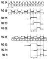
- the circuit arrangement comprises a divider 1, the clock applied to its input 3 with the period T (see FIG. 2a) to the ratio 1 divides to 2, so that the divided clock at output 5 (see Fig. 2b and Fig. 2f) compared to that at input 3 adjacent clock is halved in frequency and the Period has 2T.
- the divider 1 can be used here, for example clock-edge controlled T-flip-flop, especially as negative clock edge-controlled T flip-flop.
- This divided clock (see Fig. 2b and Fig. 2f) is from a counting unit 7, for example a counter conventional design, the input with the output 5 of the Divider 1 is connected, counted with the step size 2.
- the result of the count lies at the output 9 of the counting unit 7 of each clock cycle as a binary number, these via a data bus with the width m, for example 7 bits, is connected to an analysis unit 11.
- the result is in the downstream analysis unit 11 checked for status 0 or 1, since status "0" after the clock division in the first (Fig. 2b) or second (Fig. 2f) half of the cycle can be located.
- the analysis unit 11 is here, for example, from OR and / or NOR gates built up.
- the outputs 13 and 15 are one with the inputs 27, 29 Assignment unit 17 connected, for example, from a Latch 19, a master-slave flip-flop 21 with D input and a multiplexer 23 is constructed.
- the clock inputs 20, 22 of the latch 19 and the flip-flop 21 are each connected to the output 5 of the divider 1, so that the divided clock (Fig. 2b and Fig. 2f) on this Inputs 20, 22 are present.
- the flip-flop 21 is a negative clock edge-controlled Master-slave flip-flop, which at a first Negative flank the state present at input 29 on its Output 24 switches through (Fig. 2h) and with the following Switches the negative edge back again.
- the output 25 (FIG. 2d) of the latch 19 only takes place when a "1" or a HIGH level is present at the clock input 20 a change of state to that at input 27 attached condition.
- the input 27 of the latch 19 is hereby connected to the output 13 of the analysis unit 11 and the D input 29 of the flip-flop 21 with the output 15 of the Analysis unit 11.
- the output 24 of the flip-flop 21 has a "1" or "HIGH” input 31 of the multiplexer 23 and the output 25 of the Latches 19 with a "0" or “LOW” input 33 of the Multiplexers 23 connected.
- the clock input 35 of the Multiplexer 23 is in turn connected to the output 5 of the divider 1 connected so that the divided clock (Fig. 2b, Fig. 2f) too here.
- the output pulse can, as in the embodiment shown, advantageously the pulse width of the Have "decoded" pulse of the divided clock.
Landscapes
- Manipulation Of Pulses (AREA)
Abstract
Description
- Fig. 1
- eine schematische Darstellung einer Schaltungsanordnung nach der Erfindung, und
- Fig. 2a bis 2i
- Signalverläufe der Schaltungsanordnung nach Fig. 1.
Claims (10)
- Verfahren zum Hochgeschwindigkeitszählen von Taktzyklen eines Taktes,bei dem der Takt (Fig. 2a) in einem ersten Schritt in einem Verhältnis 1 zu n geteilt wird,die Zyklen des geteilten Taktes (Fig. 2b, Fig. 2f) von einer Zähleinheit (7) gezählt werden, wobei diese Zähleinheit (7) pro Taktzyklus n Schritte zählt,die Taktzyklen des geteilten Taktes (Fig. 2b, Fig. 2f) hinsichtlich eines Wertes 0 bis n-1 analysiert werden undbei einem Auftreten eines Wertes 0 bis n-1 in dessen Abhängigkeit eine Verzögerung eines Signals (Fig. 2e, Fig. 2i) erzeugt und ausgegeben wird.
- Verfahren nach Anspruch 1, dadurch gekennzeichnet, dass der Takt (Fig. 2a) in einem ersten Schritt in einem Verhältnis 1 zu 2 (Fig. 2b, Fig. 2f) geteilt wird.
- Verfahren nach Anspruch 1 oder 2, dadurch gekennzeichnet, dass, ausgehend von einem ersten vordefinierten Wert x bis zu einem zweiten vordefinierten Wert y, abwärts oder aufwärts gezählt wird.
- Verfahren nach Anspruch 3, dadurch gekennzeichnet, dass der erste und/oder der zweite vordefinierte Wert vor dem Zählen geladen werden kann.
- Verfahren nach Anspruch 3 oder 4, dadurch gekennzeichnet, dass der erste oder der zweite vordefinierte Wert 0 ist.
- Schaltungsanordnung zur Durchführung des Verfahrens nach einem der Ansprüche 1 bis 5, mit einer Zähleinheit (7), dadurch gekennzeichnet, dassder Zähleinheit (7) ein Teiler (1) vorgeschaltet ist, um einen Takt (Fig. 2a) in einem Verhältnis 1 zu n zu teilen,die Zähleinheit (7) als n-Schritt-Zähler ausgebildet ist,die Schaltungsanordnung eine Analyse- (11) und Zuordnungseinheit (17) aufweist, um die Zyklen des geteilten Taktes (Fig. 2b, Fig. 2g) hinsichtlich eines Wertes 0 bis n-1 zu analysieren und bei einem Auftreten eines Wertes 0 bis n-1 in dessen Abhängigkeit eine Verzögerung eines Signals (Fig. 2e, Fig. 2i) zu erzeugen und auszugeben.
- Schaltungsanordnung nach Anspruch 6, dadurch gekennzeichnet, dass der Teiler (1) als 1 zu 2 Teiler ausgebildet ist.
- Schaltungsanordnung nach Anspruch 7, dadurch gekennzeichnet, dass die Zähleinheit (7) als Dualzähler ausgebildet ist, der mit einem ersten und/oder zweiten vordefinierten Wert ladbar ist, um von einem ersten bis zu einem zweiten Wert zu zählen.
- Schaltungsanordnung nach Anspruch 8, dadurch gekennzeichnet, dass die Zähleinheit (7) als Abwärtszähler ausgebildet ist.
- Schaltungsanordnung nach Anspruch 9, dadurch gekennzeichnet, dass der zweite vordefinierte Wert 0 ist.
Applications Claiming Priority (2)
| Application Number | Priority Date | Filing Date | Title |
|---|---|---|---|
| DE1999130179 DE19930179C2 (de) | 1999-06-30 | 1999-06-30 | Hochgeschwindigkeitszähler |
| DE19930179 | 1999-06-30 |
Publications (2)
| Publication Number | Publication Date |
|---|---|
| EP1065787A2 true EP1065787A2 (de) | 2001-01-03 |
| EP1065787A3 EP1065787A3 (de) | 2001-01-24 |
Family
ID=7913196
Family Applications (1)
| Application Number | Title | Priority Date | Filing Date |
|---|---|---|---|
| EP00112902A Withdrawn EP1065787A3 (de) | 1999-06-30 | 2000-06-19 | Hochgeschwindigkeitszähler |
Country Status (2)
| Country | Link |
|---|---|
| EP (1) | EP1065787A3 (de) |
| DE (1) | DE19930179C2 (de) |
Family Cites Families (7)
| Publication number | Priority date | Publication date | Assignee | Title |
|---|---|---|---|---|
| US3764790A (en) * | 1972-03-30 | 1973-10-09 | Nasa | Technique for extending the frequency range of digital dividers |
| US4637038A (en) * | 1985-04-30 | 1987-01-13 | International Business Machines Corporation | High speed counter |
| US4975931A (en) * | 1988-12-19 | 1990-12-04 | Hughes Aircraft Company | High speed programmable divider |
| US4912734A (en) * | 1989-02-14 | 1990-03-27 | Ail Systems, Inc. | High resolution event occurrance time counter |
| DD295062A5 (de) * | 1990-06-08 | 1991-10-17 | Adw,Zentralinstitut Fuer Elektronenphysik,De | Digitaler dynamischer hochgeschwindigkeits-frequenzteiler |
| JPH06276095A (ja) * | 1993-03-18 | 1994-09-30 | Fujitsu Ltd | Pll回路 |
| EP0903858B1 (de) * | 1997-09-18 | 2004-12-22 | Infineon Technologies AG | Frequenzteiler mit geringem Stromverbrauch |
-
1999
- 1999-06-30 DE DE1999130179 patent/DE19930179C2/de not_active Expired - Fee Related
-
2000
- 2000-06-19 EP EP00112902A patent/EP1065787A3/de not_active Withdrawn
Also Published As
| Publication number | Publication date |
|---|---|
| DE19930179C2 (de) | 2001-07-05 |
| DE19930179A1 (de) | 2001-01-25 |
| EP1065787A3 (de) | 2001-01-24 |
Similar Documents
| Publication | Publication Date | Title |
|---|---|---|
| DE19734028C2 (de) | Schaltung zur glitchfreien Umschaltung digitaler Signale | |
| DE68923207T2 (de) | Schaltung zur Verhinderung eines metastabilen Zustandes. | |
| DE3818546C2 (de) | ||
| DE69502071T2 (de) | Einstellbare Verzögerungsschaltung | |
| DE2726277A1 (de) | Abtastsignaldetektor | |
| DE3784043T2 (de) | Mehrniveau-musterdetektor fuer ein einzelnes signal. | |
| DE3022746A1 (de) | Digitale phasenkomparatorschaltung | |
| DE69317986T2 (de) | Schnelle Zähler zum alternativen Auf- und Abzählen von Impulsfolgen | |
| DE69417297T2 (de) | Schaltung und Verfahren zur Unterdrückung von Störsignalen | |
| EP3918426B1 (de) | Verfahren zur time-to-digital-konversion und time-to-digital-konverter | |
| DE102004021398A1 (de) | Verfahren und Schaltungsanordnung zum Zurücksetzen einer integrierten Schaltung | |
| DE2608741A1 (de) | Anordnung und verfahren zum anzeigen eines uebergangs von einem pegel zu einem anderen pegel in einem 2-pegel-logiksignal | |
| DE19930179C2 (de) | Hochgeschwindigkeitszähler | |
| DE2938228C2 (de) | Verfahren und Schaltung zur Synchronisation | |
| DE4124005C2 (de) | ||
| DE1925917C3 (de) | Binäre Impulsfrequenz-Multiplizierschaltung | |
| EP1126615A1 (de) | Verfahren zur Frequenzteilung eines Taktsignals und Frequenzteilerschaltung zur Realisierung des Verfahrens | |
| DE19535007C2 (de) | Zählschaltung mit Ladefunktion | |
| EP0545493A2 (de) | Abtastschaltung | |
| DE3531167C1 (de) | Schaltungsanordnung zur Erzeugung eines Signals für eine Mindestzeitdauer | |
| DE3226032A1 (de) | Gatterkreis fuer einen universalzaehler | |
| DE19522839C2 (de) | Verfahren zum Testen von Impulszählern | |
| DE2738836C2 (de) | Überwachung von digitalen Signalen | |
| DE3127100C2 (de) | ||
| DE3445616C2 (de) | Anordnung zur Umsetzung eines Gray-codierten Binärwortes in ein dual-codiertes Binärwort |
Legal Events
| Date | Code | Title | Description |
|---|---|---|---|
| PUAI | Public reference made under article 153(3) epc to a published international application that has entered the european phase |
Free format text: ORIGINAL CODE: 0009012 |
|
| PUAL | Search report despatched |
Free format text: ORIGINAL CODE: 0009013 |
|
| AK | Designated contracting states |
Kind code of ref document: A2 Designated state(s): DE FR GB |
|
| AX | Request for extension of the european patent |
Free format text: AL;LT;LV;MK;RO;SI |
|
| AK | Designated contracting states |
Kind code of ref document: A3 Designated state(s): AT BE CH CY DE DK ES FI FR GB GR IE IT LI LU MC NL PT SE |
|
| AX | Request for extension of the european patent |
Free format text: AL;LT;LV;MK;RO;SI |
|
| RIC1 | Information provided on ipc code assigned before grant |
Free format text: 7H 03K 23/00 A, 7H 03K 23/66 B, 7H 03K 21/38 B |
|
| 17P | Request for examination filed |
Effective date: 20010724 |
|
| AKX | Designation fees paid |
Free format text: DE FR GB |
|
| GRAP | Despatch of communication of intention to grant a patent |
Free format text: ORIGINAL CODE: EPIDOSNIGR1 |
|
| STAA | Information on the status of an ep patent application or granted ep patent |
Free format text: STATUS: THE APPLICATION IS DEEMED TO BE WITHDRAWN |
|
| 18D | Application deemed to be withdrawn |
Effective date: 20070706 |