EP1063824B1 - Symboltaktsynchronisierung in Mehrträgerempfängern - Google Patents
Symboltaktsynchronisierung in Mehrträgerempfängern Download PDFInfo
- Publication number
- EP1063824B1 EP1063824B1 EP00111958A EP00111958A EP1063824B1 EP 1063824 B1 EP1063824 B1 EP 1063824B1 EP 00111958 A EP00111958 A EP 00111958A EP 00111958 A EP00111958 A EP 00111958A EP 1063824 B1 EP1063824 B1 EP 1063824B1
- Authority
- EP
- European Patent Office
- Prior art keywords
- signal
- ofdm
- symbol
- delay
- frequency
- Prior art date
- Legal status (The legal status is an assumption and is not a legal conclusion. Google has not performed a legal analysis and makes no representation as to the accuracy of the status listed.)
- Expired - Lifetime
Links
Images


Classifications
-
- H—ELECTRICITY
- H04—ELECTRIC COMMUNICATION TECHNIQUE
- H04L—TRANSMISSION OF DIGITAL INFORMATION, e.g. TELEGRAPHIC COMMUNICATION
- H04L27/00—Modulated-carrier systems
- H04L27/26—Systems using multi-frequency codes
- H04L27/2601—Multicarrier modulation systems
- H04L27/2647—Arrangements specific to the receiver only
- H04L27/2655—Synchronisation arrangements
- H04L27/2662—Symbol synchronisation
- H04L27/2665—Fine synchronisation, e.g. by positioning the FFT window
-
- H—ELECTRICITY
- H04—ELECTRIC COMMUNICATION TECHNIQUE
- H04L—TRANSMISSION OF DIGITAL INFORMATION, e.g. TELEGRAPHIC COMMUNICATION
- H04L27/00—Modulated-carrier systems
- H04L27/26—Systems using multi-frequency codes
- H04L27/2601—Multicarrier modulation systems
- H04L27/2647—Arrangements specific to the receiver only
- H04L27/2655—Synchronisation arrangements
- H04L27/2662—Symbol synchronisation
Definitions
- the present invention relates to apparatuses and methods for OFDM demodulation, and more particularly to an apparatus and a method for demodulating a signal transmitted under an orthogonal frequency division multiplex (OFDM) technique.
- OFDM orthogonal frequency division multiplex
- the OFDM mode is included in a multicarrier modulation scheme, and carries out OFDM signal transmission from a transmitter to a receiver.
- the transmitter assigns transmission data to a large number of subcarriers having an orthogonality relation between any adjoining two, and the subcarriers are each modulated by the transmission data assigned thereto. Thereafter, the transmitter collectively subjects the modulated subcarriers to inverse Fourier transform to generate an OFDM signal.
- the transmission data divided and assigned to the subcarriers may be prolonged in cycle, thereby the OFDM signal is characteristically not susceptive to a delay wave such as multipath.
- Such transmission under the OFDM mode is carried out on a transmission symbol basis.
- the transmission symbol is structured by a valid symbol period and a guard interval (GI).
- the valid symbol period is a period over which a signal (hereinafter, valid symbol) corresponding to the transmission data is transmitted, and is defined according to the inverse Fourier transform processing.
- the guard interval is a period over which a signal obtained by partially and cyclically repeating a waveform of the valid symbol is transmitted. The guard interval is for reducing the impact of the delay wave.
- the receiver receives the transmission symbol, and extracts the valid symbol therefrom.
- the receiver then subjects the extracted valid symbol to Fourier transform to separate the valid symbol into the subcarriers. Thereafter, the receiver demodulates each of the separated subcarriers so as to reproduce the transmission data.
- the above-described OFDM signal may take such waveform as random noise, therefore it is difficult to establish synchronization in frequency and symbol of the OFDM signal in the receiver.
- the OFDM signal is demodulated without frequency synchronization, the orthogonality relation among the subcarriers is lost and thus interference occurs.
- the receiver cannot establish symbol synchronization, that is, when the receiver cannot correctly extract the valid symbol from the transmission symbol, interference occurs between the symbols. Accordingly in either case, the receiver fails to correctly reproduce the transmission data.
- a symbol (hereinafter, synchronous symbol) being a reference to synchronization is provided at the head of a transmission frame.
- the transmission frame is structured by several predetermined transmission symbols.
- the conventional OFDM receiver which establishes symbol synchronization by using such synchronous symbol is found in Japanese Patent Laying-Open No. 11-32025 (99-32025) titled "OFDM receiver and method for detecting synchronization therein".
- the conventional technique applies a chirp symbol to the synchronous symbol.
- the conventional receiver detects symbol timing from a maximum value thereof, and establishes symbol synchronization therein.
- the receiver may receive both a direct wave and a delay wave of a transmitting signal, i.e., a combined wave thereof.
- a delay of the delay wave is within the guard interval
- the receiver can extract the valid symbol located in a section having no adjacent-symbol interference (FIG. 12A) by following the timing of the valid symbol period of the direct wave.
- FIG. 12B this is not applicable to a case where the delay of the delay wave is beyond the guard interval. It may result in extracting the valid symbol having influenced by the adjacent-symbol interference (FIG. 12B).
- the adjacent-symbol interference occurs in the receiver, there is a need for setting a section from which the valid symbol is extracted so as to minimize the interference. Note that, the diagonally shaded area in FIGS. 12A and 12B shows a part where the adjacent-symbol interference is observed.
- the symbol timing is set according to the maximum value of the correlation coefficient between the received signal and the synchronous symbol. Consequently, when the delay of the delay wave is beyond the guard interval, the conventional receiver is incapable of setting the symbol timing in such a manner as to minimize the adjacent-symbol interference.
- the transmitting signal and the received signal have a shift in frequency (hereinafter, frequency shift) therebetween, the correlation coefficient between the received signal and the synchronous symbol becomes smaller. Consequently, the conventional receiver cannot satisfactorily detect the synchronous symbol therein.
- a sampling frequency for sampling symbols may be shifted (hereinafter, sampling frequency shift) between the transmitter and the receiver. If this is the case, the symbol timing setting based on detection of the synchronous symbol as the conventional receiver is not sufficient. It leads to a shift of the symbol timing, i.e., a shift of the valid symbol period between the transmission symbols at the head and at the tail in the transmission frame.
- a first object of the present invention is to provide an apparatus for OFDM demodulation capable of setting symbol timing in such a manner as to minimize adjacent-symbol interference even if a transmission path characteristic varies with time, and a method therefor.
- a second object of the present invention is to provide an apparatus for OFDM demodulation correcting a frequency shift, if any, for satisfactory synchronous symbol detection, and a method therefor.
- a third object of the present invention is to provide an apparatus for OFDM demodulation, if a sampling frequency shift is observed, correcting the symbol timing so as not to cause a shift among valid symbol periods by the location of transmission symbols in a transmission frame, and a method therefor.
- FIGS. 1 to 7 it is described an apparatus and a method for OFDM demodulation according to a first embodiment of the present invention.
- FIG. 1 is a block diagram showing the structure of the apparatus for OFDM demodulation of the first embodiment.
- the apparatus is provided with an A/D converter 101, an quadrature detector 102, a fast Fourier transformer 103, a data demodulator 104, and a symbol timing synchronizer 111.
- the symbol timing synchronizer 111 includes an impulse response estimator 112, an integrator 108, a timing determination device 109, and an FFT window generator 110.
- the impulse response estimator 112 includes a correlator 105, a synchronous symbol generator 106, and a correlation calculator 107.
- An OFDM signal transmitted from a transmitter (not shown) is received by a tuner (not shown), and then is converted into an intermediate frequency signal arbitrarily selected by the tuner.
- the OFDM signal herein is similar to the one shown in FIG. 11.
- a chirp signal taking a strong autocorrelation, a signal in which a predetermined subcarrier is assigned a predetermined vector, or a signal taking an identical waveform periodically repeated for twice or more in the symbol period may be used.
- the synchronous symbol may be provided at the head of the respective transmission frames, or plurally provided in one transmission frame (e.g., inserted at a given interval).
- the OFDM signal converted into an intermediate frequency band signal is forwarded to the A/D converter 101.
- the A/D converter 101 converts the received OFDM signal into a time-series digital signal.
- the quadrature detector 102 receives the digital signal from the A/D converter 101, and performs orthogonality detection thereon so as to convert the signal into a baseband signal.
- the baseband signal is forwarded to both the fast Fourier transformer 103 and the symbol timing synchronizer 111.
- the symbol timing synchronizer 111 detects symbol timing of the baseband signal, and then based on a result obtained thereby, provides the fast Fourier transformer 103 with a period during which a valid symbol is extracted (valid symbol period).
- the fast Fourier transformer 103 extracts the valid symbol from each of the transmission symbols included in the baseband signal. Thereafter, the fast Fourier transformer 103 subjects the extracted valid symbols to Fourier transform so as to separate the baseband signal into subcarriers.
- the data demodulator 104 demodulates the signal separated into the subcarriers in the fast Fourier transformer 103 so as to reproduce the transmission data.
- the baseband signal converted in the quadrature detector 102 is forwarded to the correlator 105.
- the synchronous symbol generator 106 generates a synchronous symbol signal whose waveform is identical to that of the synchronous symbol inserted into the transmission frame on the transmitter side.
- Such synchronous symbol generator 106 is implemented by a memory circuit, for example.
- the memory circuit is previously stored with a signal whose waveform is identical to that of the synchronous symbol inserted into the transmission frame on the transmitter side, whereby the synchronous symbol signal can be generated by reading out the stored signal.
- the correlator 105 receives both the baseband signal outputted from the quadrature detector 102 and the synchronous symbol signal generated by the synchronous symbol generator 106.
- the correlator 105 then performs product-sum operation on the baseband signal and the synchronous symbol signal, and thus obtains a correlation vector.
- the symbol timing synchronizer 111 predicts the location of the next synchronous symbol based on the timing of the detected synchronous symbol. Thereafter, the symbol timing synchronizer 111 causes the correlator 105 to operate only for a given period before and after the predicted location, and thus obtains the correlation vector.
- the correlator 105 may take the structure shown in FIG. 2.
- the correlator 105 includes a fast Fourier transformer 703, a multiplier 701, and an inverse fast Fourier transformer 702.
- the baseband signal provided by the quadrature detector 102 is converted into a frequency-domain signal by the fast Fourier transformer 703.
- the multiplier 701 multiplies the frequency-domain signal provided by the fast Fourier converter 703 and the frequency-domain synchronous symbol signal generated by the synchronous symbol generator 106 together.
- the signal obtained by the multiplication in the multiplier 701 is subjected to inverse Fourier transform in the inverse fast Fourier transformer 702.
- the inverse Fourier-transformed signal is equivalent to the correlation vector between the baseband signal and the synchronous symbol signal.
- circuits of the inverse fast Fourier transformer 702 and the fast Fourier converter 703 can share the same structure. Accordingly, the fast Fourier transformer 703 may be used as an alternative to the inverse fast Fourier transformer 702 to subject the signal provided by the multiplier 701 to inverse Fourier transform. It is also possible to make the fast Fourier converter 703 and the fast Fourier converter 103 sharable with each other, and the signal coming from the fast Fourier transformer 103 is forwarded to the multiplier 701. With such structure, the symbol timing synchronizer 111 can be reduced in circuit size.
- the correlation calculator 107 receives the correlation vector obtained by the correlator 105, and then calculates the magnitude (correlation) thereof. If the correlation vector is supposedly indicated by ( i , q ), the correlation may be a sum of the square of i and that of q , an absolute value of the correlation vector as an approximate value, or a sum of an absolute value of i and that of q .
- the integrator 108 receives the correlation calculated by the correlation calculator 107, and then integrates the correlation. At this time, the integrator 108 regards a time length of the guard interval as an integral section width, and performs integration on an incoming signal (correlation) while sequentially shifting the integral section width.
- FIG. 3 shows an exemplary signal provided by the correlator 108.
- the integrator 108 When received an impulse-like correlation as shown in (a) of FIG. 3, the integrator 108 performs integration thereon while sequentially shifting a given integral section width, and accordingly outputs a rectangular signal having an integral section width as shown in (b) of FIG. 3.
- the integration technique applied to the integrator 108 of this embodiment is the one for outputting a rectangular response in an integral section width, it is not restrictive.
- Another possibility may be an integration technique for additionally responding before and after the rectangular response in the integral section width, or as shown in (c) of FIG. 3, an integration technique for having a response monotonously increasing before the rectangular response but a response monotonously decreasing thereafter.
- the correlation integrated by the integrator 108 (hereinafter, integrated correlation) is forwarded to the timing determination device 109.
- the timing determination device 109 determines starting (or ending) timing of the synchronous symbol. Such determination is made by detecting timing when the integrated correlation becomes maximum.
- the starting (or ending) timing determined by the timing determination device 109 is outputted to the FFT window generator 110.
- the FFT window generator 110 Based on the starting (or ending) timing, the FFT window generator 110 generates an FFT window signal, which provides the valid symbol period in each transmission symbol to the fast Fourier transformer 103.
- a time length of the transmission symbol included in the transmission frame i.e., a time length of the guard interval and that of the valid symbol are both known.
- the FFT window generator 110 can accordingly detect a head of the transmission symbols based thereon. In this manner, an FFT window signal to be generated thereby can be equivalent to the valid symbol period.
- FIG. 4 shows a correlation and an integrated correlation in the case that only a direct wave ((a) of FIG. 4) (without a delay wave) is provided to the apparatus for OFDM demodulation.
- the correlation between the direct wave and the synchronous symbol signal calculated by the correlation calculator 107 appears at the head of the direct wave. If the correlation is integrated by the integral section width which is the time length of the guard interval in the integrator 108, the integrated correlation obtained thereby is in rectangular as shown in (c) of FIG. 4. Accordingly, by setting, to the symbol timing, arbitrary timing within the interval A where the integrated correlation is maximum in the timing determination device 109, the apparatus for OFDM demodulation can successfully reproduce the transmission data without causing the between-symbol interference.
- timing at the tail of the interval A is preferably set to the symbol timing.
- FIG. 5 shows a correlation and an integrated correlation in the case that a combined wave ((c) of FIG. 5) of a direct wave ((a) thereof) and a delay wave ((b) thereof) is provided to the apparatus for OFDM demodulation due to multipath.
- FIG. 5 exemplarily shows a case that a delay of the delay wave is within the guard interval, and a power level thereof is "direct wave > delay wave” .
- the diagonally shaded area is a part where the between-symbol interference is observed.
- the correlation between the combined wave and the synchronous symbol signal calculated by the correlation calculator 107 appears in two at the head of the direct wave and at the head of the delay wave, and each is proportional to the power level thereof. If the correlation is integrated by the integral section width which is the time length of the guard interval in the integrator 108, the integrated correlation obtained thereby is as shown in (e) of FIG. 5. Therein, the interval B is the maximum. Accordingly, by setting, to the symbol timing, arbitrary timing within the interval B where the integrated correlation is maximum in the timing determination device 109, the apparatus for OFDM demodulation can successfully reproduce the transmission data without causing the between-symbol interference.
- timing at the tail of the interval B is preferably set to the symbol timing.
- FIG. 6 shows a correlation and an integrated correlation in the case that a combined wave ((d) of FIG. 6) of a direct wave ((a) thereof) and first and second delay waves ((b) and (c) thereof) is provided to the apparatus for OFDM demodulation due to multipath.
- FIG. 6 exemplarily shows a case that a delay of the first delay wave is within the guard interval but a delay of the second delay wave, and each power level thereof is "first delay wave > second delay wave > direct wave".
- the diagonally shaded area is a part where the between-symbol interference is observed.
- the correlation between the combined wave and the synchronous symbol signal calculated by the correlation calculator 107 appears in three at the head of the direct wave, at the head of the first delay wave, and at the head of the second delay wave, and each is proportional to the power level thereof. If the correlation is integrated by the integral section width which is the time length of the guard interval in the integrator 108, the integrated correlation obtained thereby is as shown in (f) of FIG. 6. Therein, the interval C is the maximum. As is known from (d) of FIG. 6, in the case that a delay of the delay wave (second delay wave) is beyond the guard interval, the between-symbol interference occurs no matter how the symbol timing is set.
- the timing determination device 109 arbitrary timing within the interval C where the integrated correlation is maximum is set to the symbol timing.
- the apparatus for OFDM demodulation can successfully reproduce the transmission data while minimizing influence of the between-symbol interference.
- setting the symbol timing in the interval C results in the between-symbol interference occurring at the tail of the valid symbol period.
- Such between-symbol interference is due to the direct wave whose power level is low, whereby the influence of the interference can be minimized.
- FIG. 7 shows a correlation and an integrated correlation in the case that a combined wave ((c) of FIG. 7) of a direct wave ((a) thereof) and a delay wave ((b) thereof) is provided to the apparatus for OFDM demodulation due to multipath.
- FIG. 7 exemplarily shows a case that a delay of the delay wave is beyond the guard interval, and a power level thereof is "direct wave > delay wave" .
- the diagonally shaded area is a part where the between-symbol interference is observed.
- the correlation between the combined wave and the synchronous symbol signal calculated by the correlation calculator 107 appears in two at the head of the direct wave and at the head of the delay wave, and each is proportional to the power level thereof. If the correlation is integrated by the integral section width which is the time length of the guard interval in the integrator 108, the integrated correlation obtained thereby is as shown in (e) of FIG. 7. Therein, the interval D is the maximum. Accordingly, by setting, to the symbol timing, arbitrary timing within the interval D where the integrated correlation is maximum in the timing determination device 109, the apparatus for OFDM demodulation can successfully reproduce the transmission data while minimizing the influence of the between-symbol interference.
- timing at the tail of the interval D is preferably set to the symbol timing for the purpose.
- the timing of the valid symbol period is controlled for Fourier transform to be so carried out as to minimize the between-symbol interference. This is done by first calculating a correlation between an incoming OFDM signal and a prestored synchronous symbol signal, secondly integrating the correlation by a predetermined integral section width, and lastly based on the integrated correlation obtained thereby, detecting the synchronous symbol.
- the OFDM signal can be demodulated, i.e., the transmission data can be reproduced with the between-symbol interference minimized even if a transmission path characteristic varies with time.
- FIG. 8 it is described an apparatus and a method for OFDM demodulation according to a second embodiment of the present invention.
- FIG. 8 is a block diagram showing the structure of an apparatus for OFDM demodulation of the second embodiment.
- the apparatus is provided with the A/D converter 101, the quadrature detector 102, the fast Fourier transformer 103, the data demodulator 104, the symbol timing synchronizer 111, and a first frequency synchronizer 207.
- the first frequency synchronizer 207 includes a delay device 201, a multiplier 202, an averaging device 203, a frequency error calculator 204, a holder 205, and a frequency corrector 206.
- the apparatus for OFDM demodulation of the second embodiment is additionally provided with the first frequency synchronizer 207 compared with the apparatus of the first embodiment.
- the first frequency synchronizer 207 estimates and corrects a frequency shift among subcarriers based on a synchronous symbol to be inputted.
- Other constituents in the apparatus of the second embodiment are the same as those in the apparatus of the first embodiment, and are denoted by the same reference numerals and not described again.
- a baseband signal converted in the quadrature detector 102 is forwarded to both the delay device 201 and the multiplier 202.
- the delay device 201 delays the baseband signal for a predetermined number of samplings for output. The number of samplings is determined depending on each characteristic of the synchronous symbols. For instance, when the synchronous symbol is provided with the guard interval, the number of samplings for the valid symbol is set thereto.
- the multiplier 202 multiplies the baseband signal outputted from the quadrature detector 102 by a complex conjugate of the baseband signal delayed in the delay device 201, thus obtains a phase-difference vector (indicates how much the phase is shifted) therebetween.
- a signal included in the guard interval is the one obtained by cyclically repeating a waveform of the valid symbol. Accordingly, multiplying a not-delayed signal and a signal delayed for the number of samplings for the valid symbol leads to a phase-difference vector among the same waveforms.
- This utilizes that, when a frequency shift is observed among subcarriers, a phase is differed between a signal in the vicinity of the head and a signal in the vicinity of the tail of the transmission symbol. Accordingly, a phase-difference vector calculated by the multiplier 202 tells a frequency shift (frequency error) at estimate.
- the number of samplings predetermined for the delay device 201 is regarded as being equal to that in a cycle of the signal. Specifically, in the case that the synchronous symbol is a signal having an identical waveform repeated for two cycles in the symbol period, assuming that the number of samplings in a cycle is N, the signal in the delay device 201 is delayed also for the N samplings. In this manner, the multiplier 202 accordingly obtains a phase-difference among the same waveforms.
- the averaging device 203 sequentially receives the phase-difference vector obtained by the multiplier 202, and then averages the phase-difference vectors. At this time, the averaging device 203 may calculate an average-shift of the phase-difference vectors based on the number of samplings set by the delay device 201. Thereby, the averaging device 203 obtains an average phase-difference vector (phase shift on average) based on the number of samplings. Note that, by lengthening the cycle of the waveform repeated in the synchronous symbol on the transmitter side, the average phase-difference vector to be obtained by the apparatus for OFDM demodulation can be improved in accuracy.
- the frequency error calculator 204 is provided with the average phase-difference vector obtained by the averaging device 203, and then calculates an arc tangent (tan -1 ) thereof so as to obtain a frequency error signal.
- the frequency error signal is forwarded to the holder 205.
- the holder 205 holds the frequency error signal with the ending timing of the synchronous symbol outputted from the timing determination device 109.
- the holder 205 then outputs the frequency error signal on hold to the frequency corrector 206. With such hold processing, it becomes possible to utilize the frequency error signal obtained from the synchronous symbol for frequency correction of data symbols subsequent to the synchronous symbol.
- the frequency corrector 206 Based on the frequency error signal, the frequency corrector 206 performs frequency correction on the baseband signal converted by the quadrature detector 102. Such frequency correction is carried out by multiplying the baseband signal by a complex SIN wave corresponding to the frequency error.
- the baseband signal after the frequency correction utilizing the synchronous symbol is forwarded to the fast Fourier transformer 103 for Fourier transform, then is demodulated in the data demodulator 104. In this manner, the transmission data is reproduced in the data demodulator 104.
- a frequency shift of an incoming OFDM signal can be corrected. This is implemented by averaging a phase shift among synchronous symbols, and from the average phase shift obtained thereby, a frequency error is calculated for the purpose.
- demodulation can be carried out with higher accuracy first by correcting a frequency shift with a synchronous symbol identical to the one used for symbol synchronization, and then subjecting an OFDM signal after the correction to Fourier transform with symbol timing.
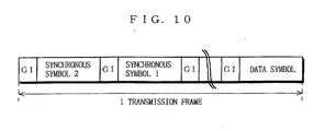
- FIGS. 9 and 10 it is described an apparatus and a method for OFDM demodulation according to a third embodiment of the present invention.
- FIG. 9 is a block diagram showing the structure of the apparatus for OFDM demodulation of the third embodiment.
- the apparatus is provided with the A/D converter 101, the quadrature detector 102, the fast Fourier transformer 103, the data demodulator 104, the symbol timing synchronizer 111, the first frequency synchronizer 207, and a second frequency synchronizer 310.
- the second frequency synchronizer 310 includes a delay device 301, a multiplier 302, an averaging device 303, a frequency error calculator 204, a holder 305, a filter 306, an absolute value calculator 307, a timing determination device 308, and a frequency corrector 309.
- the apparatus for OFDM demodulation of the third embodiment is additionally provided with the second frequency synchronizer 310 compared with the apparatus of the second embodiment.
- the second frequency synchronizer 310 estimates and corrects a frequency shift among subcarriers based on a synchronous symbol different from the one used in the first frequency synchronizer 207.
- Other constituents in the apparatus of the third embodiment are the same as those in the apparatuses of the first and the second embodiments, and are denoted by the same reference numerals and not described again.
- FIG. 10 shows the structure of an OFDM signal to be provided to the apparatus of the third embodiment.
- a synchronous symbol 1 is the one used in the symbol timing synchronizer 111 and the first frequency synchronizer 207, while a synchronous symbol 2 is the one used in the second frequency synchronizer 310.
- the synchronous symbol 2 may be a signal having an identical waveform periodically repeated in the symbol period.
- a transmission symbol in which a guard interval is provided to a valid symbol period can be exemplarily used as the synchronous symbol 2.
- the repetition cycle of the waveform in the symbol period is set to be shorter than that in the synchronous symbol 1.
- the apparatus for OFDM demodulation of the third embodiment After received such OFDM signal, the apparatus for OFDM demodulation of the third embodiment first establishes frequency synchronization by using the synchronous symbol 2, and then establishes synchronization in symbol timing and frequency by using the synchronous symbol 1. Accordingly, accuracy in detecting the synchronous symbol 1 can be further improved.
- a baseband signal converted in the quadrature detector 102 is forwarded to both the delay device 301 and the multiplier 302.
- the delay device 301 delays the baseband signal for a predetermined number of samplings for output. The number of samplings is determined depending on a characteristic of the synchronous symbol 2. For instance, when the synchronous symbol 2 is provided with the guard interval, the number of samplings for the valid symbol is set thereto.
- the multiplier 302 multiplies the baseband signal outputted from the quadrature detector 102 by a complex conjugate of the baseband signal delayed in the delay device 301, thus obtains a phase-difference vector (indicates how much the phase is shifted) therebetween.
- a signal included in the guard interval is the one obtained by cyclically repeating a waveform of the valid symbol. Accordingly, in a similar manner to the above, multiplying a not-delayed signal and a signal delayed for the number of samplings for the valid symbol leads to a phase-difference vector among the same waveforms. Accordingly, a phase-difference vector calculated by the multiplier 302 tells a frequency shift (frequency error) at estimate.
- the number of samplings predetermined for the delay device 301 is regarded as being equal to that in a cycle of the signal.
- the multiplier 302 accordingly obtains a phase-difference among the same waveforms.
- the repetition cycle of the waveform in the symbol period in the synchronous symbol 2 may be set shorter than that in the synchronous symbol 1. If that is the case, the number of samplings in the delay device 301 can be decreased in the apparatus for OFDM demodulation, whereby the frequency error can be estimated in a quicker manner. Further, the synchronous symbols 1 and 2 may share the same waveform.
- the averaging device 303 sequentially receives the phase-difference vector obtained by the multiplier 302, and then averages the phase-difference vectors. At this time, the averaging device 303 may calculate an average-shift of the phase-difference vectors based on the number of samplings set by the delay device 301. Thereby, the averaging device 303 obtains an average phase-difference vector (phase shift on average) based on the number of samplings.
- the frequency error calculator 304 is provided with the average phase-difference vector obtained by the averaging device 303, and then calculates an arc tangent (tan -1 ) thereof so as to obtain a frequency error signal. The frequency error signal obtained thereby in the frequency error calculator 304 is forwarded to the holder 305.
- the filter 306 sequentially receives the phase-difference vector obtained by the multiplier 302 for smoothing.
- the absolute value calculator 307 receives the smoothed phase-difference vectors from the filter 306, and then determines the magnitude thereof.
- the timing determination device 308 receives the magnitude of the phase-difference vectors determined by the absolute value calculator 307, and according thereto, determines an ending timing of the synchronous symbol 2.
- the phase-difference vectors remain invariable in magnitude in a period of the synchronous symbol 2 but otherwise randomly vary. Therefore, the timing determination device 308 detects whether the phase-difference vectors in a predetermined period remain invariable in magnitude.
- the timing determination device 308 determines timing when the phase-difference vectors start to change in magnitude as an ending time of the synchronous symbol 2. Such determination is made by first calculating a difference in magnitude between the phase-difference vectors being currently sampled and those sampled one sampling before, and then detects whether the difference is beyond a predetermined threshold value. In an alternate manner, the timing determination device 308 first detects and holds a value indicating invariability of the phase-difference vectors, and then detects a time point when the phase-difference vectors start to change proportionately less than the value (e.g., 80%).
- the value e.g., 80%
- the holder 305 holds the frequency error signal with the ending timing of the synchronous symbol 2 outputted from the timing determination device 308.
- the holder 305 then outputs the frequency error signal on hold to the frequency corrector 309.
- the frequency corrector 309 Based on the frequency error signal, the frequency corrector 309 performs frequency correction on the baseband signal converted by the quadrature detector 102. Such frequency correction is carried out by multiplying the baseband signal by a complex SIN wave corresponding to the frequency error.
- the baseband signal after the frequency correction utilizing the synchronous symbol 2 in the second frequency synchronizer 310 is forwarded to both the symbol timing synchronizer 111 and the first frequency synchronizer 207. Thereafter, the symbol timing synchronizer 111 establishes symbol synchronization utilizing data symbols frequency-corrected based on the synchronous symbol 2. The first frequency synchronizer 207 also performs frequency correction with the synchronous symbol 1 frequency-corrected based on the synchronous symbol 2.
- the frequency-corrected baseband signal utilizing the synchronous symbol 1 is forwarded to the fast Fourier transformer 103 for Fourier transform, then is demodulated in the data demodulator 104. In this manner, the transmission data is reproduced in the data demodulator 104.
- a frequency shift is corrected in the second frequency synchronizer 310 before a correlation between an OFDM signal and a synchronous symbol signal is calculated.
- calculation processing carried out in the apparatuses of first to third embodiments can be implemented by a digital signal processor (DSP), for example. Still further, such calculation processing can be implemented by carrying out a program recorded on a recording medium as a computer program for steps of the calculation processing.
- DSP digital signal processor
Claims (32)
- OFDM-Demodulationsvorrichtung zum Demodulieren eines OFDM-Signals, welches ein spezifisches synchrones Symbol und ein OFDM-Datensymbol enthält, strukturiert durch eine gültige Symbolperiode und ein Schutzintervall, wobei die Vorrichtung umfasst:einen Impulsantwortschätzteil (112) zum Schätzen einer Impulsantwort;einen Bestimmungsteil (109) zum Erkennen von Symboltiming;einen Fenstertimingerzeugungsteil (110) zum Erzeugen gemäß dem Symboltiming, Fenstertiming einschließend Information, die in der Lage ist, die gültige Symbolperiode bereitzustellen; undeinen Fouriertransformationsteil (103) zum Unterwerfen des OFDM-Signals einer Fouriertransformation gemäß dem Fenstertiming;dadurch gekennzeichnet, dass sie weiterhin umfasst
einen Integrationsteil (108) zum Integrieren einer Ausgabe, erhalten durch Schätzen in dem Impulsantwortschätzteil (112); und darin, dass
der Impulsantwortschätzteil (112) die Impulsantwort von dem OFDM-Signal schätzt; und
das Symboltiming, welches durch den Bestimmungsteil (109) erkannt ist, eine Periode anzeigt, wo die Ausgabe, erhalten durch Integration in dem Integrationsteil (108), maximal ist. - OFDM-Demodulationsvorrichtung nach Anspruch 1, worin eine identische Wellenform zweifach oder öfter periodisch übertragen wird in dem synchronen Symbol, wobei die Vorrichtung weiterhin umfasst:einen Verzögerungsteil (201) zum Verzögern des OFDM-Signals, um eine vorherbestimmte Anzahl an Abtastungen;einen Multiplikationsteil (202) zum Multiplizieren eines Signals, erhalten durch Verzögerung in dem Verzögerungsteil (201) mit dem OFDM-Signal;einen Mittelwertbildungsteil (203) zum Mitteln eines Signals, erhalten durch Multiplizieren in dem Multiplizierteil (202);einen Frequenzfehlerberechnungsteil (204) zum Berechnen eines Frequenzfehlers, basierend auf einem Signal, erhalten durch Mitteln in dem Mittelwertbildungsteil (203);einen Halteteil (205) zum Halten des Frequenzfehlers gemäß dem Symboltiming; undeinen Frequenzkorrekturteil (206) zum Korrigieren einer Frequenzverschiebung des OFDM-Signals gemäß dem Frequenzfehler, bereitgestellt durch den Halteteil 205, worinder Fouriertransformationsteil (103) das OFDM-Signal, worin die Frequenzverschiebung durch den Frequenzkorrekturteil (206) gemäß dem Fenstertiming korrigiert ist, einer Fouriertransformation unterwirft.
- OFDM-Demodulationsvorrichtung nach Anspruch 1, wobei, wenn eine identische Wellenform periodisch zweifach oder öfter übertragen wird in dem synchronen Symbol, die Vorrichtung weiterhin umfasst:einen ersten Verzögerungsteil (301) zum Verzögern des OFDM-Signals (hiernach erstes OFDM-Signal) für eine erste vorherbestimmte Anzahl an Abtastungen;einen ersten Multiplikationsteil (302) zum Multiplizieren eines Signals, erhalten durch Verzögerung in dem ersten Verzögerungsteil (301) mit dem ersten OFDM-Signal;einen ersten Mittelwertbildungsteil (303) zum Mitteln eines Signals, erhalten durch Multiplizieren in dem ersten Multiplikationsteil (302);einen ersten Frequenzfehlerberechnungsteil (304) zum Berechnen eines ersten Frequenzfehlers, basierend auf einem Signal, erhalten durch Mitteln in dem ersten Mittelwertbildungsteil (303);einen Filterteil (306) zum Glätten eines Signals, erhalten durch Multiplizieren in dem ersten Multiplikationsteil (302);einen Absolutwertberechnungsteil (307) zum Berechnen eines Absolutwerts eines Signals, erhalten durch Glätten in dem Filterteil (306);einen ersten Bestimmungsteil (308) zum Bestimmen gemäß dem Absolutwert, einer Korrelation zwischen dem ersten OFDM-Signal und dem Signal, welches durch Verzögern in dem ersten Verzögerungsteil 301 erhalten ist und Erkennen von Symboltiming des ersten OFDM-Signals;einen ersten Halteteil (305) zum Halten des ersten Frequenzfehlers gemäß dem Symboltiming, welches durch den ersten Bestimmungsteil (308) erkannt ist;ein erster Frequenzkorrekturteil (309) zum Korrigieren einer Frequenzverschiebung des ersten OFDM-Signals gemäß dem ersten Frequenzfehler, der durch den ersten Halteteil (305) bereitgestellt ist;einen zweiten Verzögerungsteil (201) zum Verzögern, um eine zweite vorherbestimmte Anzahl an Abtastungen, des ersten OFDM-Signals, in welchem die Frequenzverschiebung durch den ersten Frequenzkorrekturteil (309) korrigiert ist (hiernach zweites OFDM-Signal);einen zweiten Multiplikationsteil (202) zum Multiplizieren eines Signals, erhalten durch Verzögern in dem zweiten Verzögerungsteil (201) mit dem zweiten OFDM-Signal;einen zweiten Mittelwertbildungsteil (203) zum Mitteln eines Signals, erhalten durch Multiplizieren in dem zweiten Multiplikationsteil (202);einen zweiten Frequenzfehlerberechnungsteil (204) zum Berechnen eines zweiten Frequenzfehlers, basierend auf einem Signal, erhalten durch Mitteln in dem zweiten Mittelwertbildungsteil (203);einen zweiten Halteteil (205) zum Halten des Frequenzfehlers gemäß dem Symboltiming, welches durch den Bestimmungsteil (109) erkannt ist; undeinen zweiten Frequenzkorrekturteil (206) zum Korrigieren eines Frequenzfehlers des zweiten OFDM-Signals gemäß dem zweiten Frequenzfehler, welcher durch den zweiten Halteteil (205) bereitgestellt ist, worinder Impulsantwortschätztcil (112) die Impulsantwort von dem zweiten OFDM-Signal schätzt undder Fouriertransformationsteil (103) das zweite OFDM-Signal, worin eine Frequenzverschiebung durch den zweiten Frequenzkonversionsteil (206) gemäß dem Fenstertiming korrigiert ist, einer Fouriertransformation unterwirft.
- OFDM-Demodulationsvorrichtung nach Anspruch 1, worin der Integrationsteil (108) eine Zeitlänge des Schutzintervalls als einen Integrationsabschnitt betrachtet und ein eingehendes Signal integriert, während er die Lage des Integrationsabschnitts mit Bezug auf das eingehende Signal sequentiell verschiebt.
- OFDM-Demodulationsvorrichtung nach Anspruch 1, worin der Integrationsteil (108) eine Zeitlänge des Schutzintervalls und eine vorherbestimmte Zeitlänge vor und nach dem Schutzintervall als einen Integrationsabschnitt betrachtet und durch Integrieren eines eingehenden Signals, während er sequentiell die Lage des Integrationsabschnitts mit Bezug auf das eingehende Signal verschiebt, vor und nach einer Rechteckimpulsantwort in der Zeitlänge des Schutzintervalls antwortet.
- OFDM-Demodulationsvorrichtung nach Anspruch 1, worin der Integrationsteil (108) eine Zeitlänge des Schutzintervalls und eine vorherbestimmte Zeitlänge vor und nach dem Schutzintervall als einen Integrationsabschnitt betrachtet und durch Integrieren eines eingehenden Signals, während er die Lage des Integrationsabschnitts mit Bezug auf das eingehende Signal sequentiell verschiebt, monoton steigend vor einer Rechteckimpulsantwort in der Zeitlänge des Schutzintervalls antwortet, aber danach monoton fallend.
- OFDM-Demodulationsvorrichtung nach Anspruch 1, worin der Impulsantwortschätzteil (112) umfasst:einen synchronen Symbolerzeugungsteil (106) zum Erzeugen eines Signals, das identisch zu dem synchronen Symbol ist;einen Korrelationsteil (105) zum Berechnen eines Signals, das anzeigt, wie das durch den synchronen Symbolerzeugungsteil erzeugte Signal und das OFDM-Signal miteinander korreliert sind; undeinen Korrelationsberechnungsteil (107) zum Berechnen einer Korrelation von dem Signal, das durch Berechnen in den Korrelationsteil (105) erhalten wurde.
- OFDM-Demodulationsvorrichtung nach Anspruch 1, worin der Impulsantwortschätzteil (112) umfasst:ein synchrones Symbolerzeugungsteil (106) zum Erzeugen eines Signals, dessen Frequenzbereich identisch zu dem synchronen Symbol ist;ein Multiplikationsteil (701) zum Multiplizieren eines Signals, das durch den Fouriertransformationsteil (103) bereitgestellt ist, mit dem Signal, welches durch das synchrone Symbolerzeugungsteil (106) bereitgestellt ist;ein inverses Fouriertransformationsteil (702) zum Unterwerfen eines Signals, erhalten durch Multiplizieren in dem Multiplikationsteil (701), einer inversen Fouriertransformation; undein Korrelationsberechnungsteil (107) zum Berechnen einer Korrelation von einem Signal, das durch den inversen Fouriertransformationsteil (702) bereitgestellt ist.
- OFDM-Demodulationsvorrichtung nach Anspruch 7, worin der Korrelationsberechnungsteil (107) einen Absolutwert eines komplexen Vectors (i, q) des eingehenden Signals berechnet.
- OFDM-Demodulationsvorrichtung nach Anspruch 8, worin der Korrelationsberechnungsteil (107) einen Absolutwert eines komplexen Vectors (i, q) des eingehenden Signals berechnet.
- OFDM-Demodulationsvorrichtung nach Anspruch 7, worin der Korrelationsberechnungsteil (107) eine Summe eines Absolutwerts von i und einem Absolutwert von q von dem komplexen Vector (i, q) des eingehenden Signals berechnet.
- OFDM-Demodulationsvorrichtung nach Anspruch 8, worin der Korrelationsberechnungsteil (107) eine Summe eines Absolutwerts von i und einem Absolutwert von q des komplexen Vectors (i, q) des eingehenden Signals berechnet.
- OFDM-Demodulationsvorrichtung nach Anspruch 7, worin der Korrelationsberechnungsteil (107) eine Summe eines Quadrates von i und eines Quadrates von q von dem komplexen Vector (i, q) des eingehenden Signals berechnet.
- OFDM-Demodulationsvorrichtung nach Anspruch 8, worin der Korrelationsberechnungsteil (107) eine Summe aus einem Quadrat von i und einem Quadrat von q von dem komplexen Vector (i, q) des eingehenden Signals berechnet.
- OFDM-Demodulationsvorrichtung nach Anspruch 3, worin der erste Bestimmungsteil (308) den Absolutwert empfängt, welcher durch den Absolutwertberechnungsteil (307) berechnet ist, einen Wert für Invariabilität davon erkennt und dann den Absolutwert erkennt, welcher ein vorherbestimmtes Verhältnis zu dem invariablen Wert zeigt.
- OFDM-Demodulationsverfahren zum Demodulieren eines OFDM-Signals, welches ein spezifisches synchrones Symbol und ein OFDM-Datensymbol enthält, strukturiert durch eine gültige Symbolperiode und ein Schutzintervall, wobei das Verfahren umfasst:einen Impulsantwortschätzschritt zum Schätzen einer Impulsantwort;einen Bestimmungsschritt zum Bestimmen von Symboltiming;einen Fenstertimingerzeugungsschritt zum Erzeugen gemäß dem Symboltiming, Fenstertiming einschließlich Information, die in der Lage ist, die gültige Symbolperiode bereitzustellen; undeinen Fouriertransformationsschritt zum Unterwerfen des OFDM-Signals einer Fouriertransformation gemäß dem Fenstertiming;dadurch gekennzeichnet, dass es ferner umfasst
einen Integrationsschritt zum Integrieren einer Ausgabe, erhalten durch Schätzen in dem Impulsantwortschätzschritt; und dadurch, dass
in dem Impulsantwortschätzschritt die Impulsantwort von dem OFDM-Signal geschätzt wird; und
das Symboltiming, welches in dem Bestimmungsschritt erkannt wurde, eine Periode anzeigt, wo die durch Integration in dem Integrationsschritt erhaltene Ausgabe maximal ist. - OFDM-Demodulationsverfahren nach Anspruch 16, wobei, wenn eine identische Wellenform zweifach oder öfter periodisch übertragen wird in dem synchronen Symbol, das Verfahren weiterhin die Schritte umfasst:Verzögern des OFDM-Signals um eine vorherbestimmte Anzahl von Abtastungen;Multiplizieren eines Signals, erhalten durch Verzögerung in dem Verzögerungsteil mit dem OFDM-Signal;Mitteln eines Signals, erhalten durch Multiplizieren in dem Multiplizierteil;Berechnen eines Frequenzfehlers, basierend auf einem Signal, erhalten durch Mitteln in dem Mittelwertbildungsteil;Halten des Frequenzfehlers gemäß dem Symboltiming; undKorrigieren einer Frequenzverschiebung des OFDM-Signals gemäß dem Frequenzfehler, welcher in dem Halteschritt bereitgestellt wird, worinin dem Fouriertransformationsschritt das OFDM-Signal mit korrigierter Frequenzverschiebung einer Fouriertransformation gemäß dem Fenstertiming unterworfen wird.
- OFDM-Demodulationsverfahren nach Anspruch 16, wobei, wenn eine identische Wellenform zweifach oder öfter periodisch übertragen wird in dem synchronen Symbol, das Verfahren weiterhin umfasst:einen ersten Verzögerungsschritt des Verzögerns des OFDM-Signals (hiernach erstes OFDM-Signal) für eine erste vorherbestimmte Anzahl an Abtastungen;einen ersten Multiplikationsschritt des Multiplizierens eines Signals, erhalten durch Verzögerung in dem ersten Verzögerungsschritt, mit dem ersten OFDM-Signal;einen ersten Mittelwertbildungsschritt zum Mitteln eines Signals, erhalten durch Multiplizieren in dem ersten Multiplikationsschritt;einen Schritt des Berechnens eines ersten Frequenzfehlers, basierend auf einem Signal, erhalten durch Mittelung in dem ersten Mittelwertbildungsschritt;einen Schritt des Glättens eines Signals, erhalten durch Multiplizieren in dem ersten Multiplikationsschritt;einen Schritt des Berechnens eines Absolutwerts eines Signals, erhalten durch Glätten in dem Glättungsschritt;einen ersten Bestimmungsschritt des Bestimmens gemäß dem Absolutwert, einer Korrelation zwischen dem ersten OFDM-Signal und dem Signal, welches durch Verzögerung in dem ersten Verzögerungsschritt erhalten wurde, und Erkennen von Symboltiming des ersten OFDM-Signals;einen Schritt des Haltens des ersten Frequenzfehlers gemäß dem Symboltiming, welches im ersten Bestimmungsschritt erkannt wurde;einen Schritt des Korrigierens einer Frequenzverschiebung des ersten OFDM-Signals gemäß dem gehaltenen ersten Frequenzfehler;einen zweiten Verzögerungsschritt des Verzögerns, um eine zweite vorherbestimmte Anzahl an Abtastungen, des ersten OFDM-Signals mit korrigierter Frequenzverschiebung (hiernach zweites OFDM-Signal);einen zweiten Multiplikationsschritt des Multiplizierens eines Signals, erhalten durch Verzögerung in dem zweiten Verzögerungsschritt, mit dem zweiten OFDM-Signal;einen zweiten Mittelwertbildungsschritt zum Mitteln eines Signals, erhalten durch Multiplikation in dem zweiten Multiplikationsschritt;einen Schritt zum Berechnen eines zweiten Frequenzfehlers, basierend auf einem Signal, erhalten durch Mitteln in dem zweiten Mittelwertbildungsschritt;einen Schritt des Haltens des zweiten Frequenzfehlers gemäß dem in dem Bestimmungsschritt erkannten Symboltiming; undeinen Schritt des Korrigierens einer Frequenzverschiebung des zweiten OFDM-Signals gemäß dem gehaltenen zweiten Frequenzfehler, worinin dem Schätzschritt eine Impulsantwort von dem zweiten OFDM-Signal geschätzt wird undin dem Fouriertransformationsschritt gemäß dem Fenstertiming das zweite OFDM-Signal mit korrigierter Frequenzverschiebung einer Fouriertransfonnation unterworfen wird.
- OFDM-Demodulationsverfahren nach Anspruch 16, worin in dem Integrationsschritt eine Zeitlänge des Schutzintervalls als ein Integrationsabschnitt betrachtet wird und ein eingehendes Signal integriert wird, während die Lage des Integrationsabschnitts sequentiell verschoben wird mit Bezug auf das eingehende Signal.
- OFDM-Demodulationsverfahren nach Anspruch 16, worin in dem Integrationsschritt eine Zeitlänge des Schutzintervalls und eine vorherbestimmte Zeitlänge vor und nach dem Schutzintervall als ein Integrationsabschnitt betrachtet werden und durch Integrieren eines eingehenden Signals, während die Lage des Integrationsabschnitts mit Bezug auf das eingehende Signal verschoben wird, eine Antwort vor und nach einer Rechteckimpulsantwort, welche die Zeitlänge des Schutzintervalls hat, bereitgestellt wird.
- OFDM-Demodulationsverfahren nach Anspruch 16, worin in dem Integrationsschritt eine Zeitlänge des Schutzintervalls und eine vorherbestimmte Zeitlänge vor und nach dem Schutzintervall als ein Integrationsabschnitt betrachtet wird und durch Integrieren eines eingehenden Signals, während die Lage des Integrationsabschnitts mit Bezug auf das eingehende Signal sequentiell verschoben wird, eine Antwort mit monotonem Ansteigen vor einer rechteckigen Impulsantwort, welche die Zeitlänge des Schutzintervalls hat, aber monotonem Abfallen danach, bereitgestellt wird.
- OFDM-Demodulationsverfahren nach Anspruch 16, worin der Schätzschritt die Schritte umfasst:Erzeugen eines Signals, das identisch mit dem synchronen Symbol ist;Berechnen eines Signals, welches eine Korrelation zwischen einem Signal, das in dem Erzeugungsschritt erzeugt wurde, und dem OFDM-Signal anzeigt; undBerechnen einer Korrelation von einem Signal erhalten in dem Berechnungsschritt.
- OFDM-Demodulationsverfahren nach Anspruch 16, worin der Schätzschritt die Schritte umfasst:Erzeugen eines Frequenzbereichsignals, identisch zu dem synchronen Symbol;Multiplizieren eines Signals, erhalten in dem Fouriertransformationsschritt mit dem Frequenzbereichssignal, das in dem Erzeugungsschritt erzeugt wurde;Inverse Fouriertransformation eines Signals, erhalten in dem Multiplizierungsschritt; undBerechnen einer Korrelation von dem invers transformierten Signal.
- OFDM-Demodulationsverfahren nach Anspruch 22, worin in dem Berechnungsschritt ein Absolutwert eines komplexen Vectors (i, q) des eingehenden Signals berechnet wird.
- OFDM-Demodulationsverfahren nach Anspruch 23, worin in dem Berechnungsschritt ein Absolutwert eines komplexen Vectors (i, q) des eingehenden Signals berechnet wird.
- OFDM-Demodulationsverfahren nach Anspruch 22, worin in dem Berechnungsschritt eine Summe von einem Absolutwert von i und einem Absolutwert von q berechnet wird von dem komplexen Vector (i, q) des eingehenden Signals.
- OFDM-Demodulationsverfahren nach Anspruch 23, worin in dem Berechnungsschritt eine Summe von einem Absolutwert von i und einem Absolutwert von q berechnet wird von dem komplexen Vector (i, q) des eingehenden Signals.
- OFDM-Demodulationsverfahren nach Anspruch 22, worin in dem Berechnungsschritt eine Summe von einem Quadrat von i und einem Quadrat von q berechnet wird von dem komplexen Vector (i, q) des eingehenden Signals.
- OFDM-Demodulationsverfahren nach Anspruch 23, worin in dem Berechnungsschritt eine Summe von einem Quadrat von i und einem Quadrat von q berechnet wird von einem komplexen Vector (i, q) des eingehenden Signals.
- OFDM-Demodulationsverfahren nach Anspruch 18, worin in dem ersten Bestimmungsschritt ein Wert für Invariabilität des Absolutwerts erkannt wird und dann der Absolutwert, welcher ein vorherbestimmtes Verhältnis zu dem invariablen Wert zeigt, erkannt wird.
- OFDM-Demodulationsvorrichtung nach Anspruch 1, worin
das OFDM-Datensymbol weiter aus einer Vielzahl von Subträgern erzeugt wird; und
der Fouriertransformationsteil (103) ein Separator ist, der eingerichtet ist, das OFDM-Signal in die Vielzahl von Subträgern gemäß dem Fenstertiming zu separieren. - OFDM-Demodulationsverfahren nach Anspruch 16, worin
das OFDM-Datensymbol weiter aus einer Vielzahl von Subträgern erzeugt wird; und
der Fouriertransformationsschritt ein Separationsschritt zum Separieren des OFDM-Signals in die Vielzahl von Subträgern gemäß dem Fenstertiming ist.
Applications Claiming Priority (2)
| Application Number | Priority Date | Filing Date | Title |
|---|---|---|---|
| JP17498499 | 1999-06-22 | ||
| JP17498499 | 1999-06-22 |
Publications (3)
| Publication Number | Publication Date |
|---|---|
| EP1063824A2 EP1063824A2 (de) | 2000-12-27 |
| EP1063824A3 EP1063824A3 (de) | 2003-08-27 |
| EP1063824B1 true EP1063824B1 (de) | 2006-08-02 |
Family
ID=15988197
Family Applications (1)
| Application Number | Title | Priority Date | Filing Date |
|---|---|---|---|
| EP00111958A Expired - Lifetime EP1063824B1 (de) | 1999-06-22 | 2000-06-16 | Symboltaktsynchronisierung in Mehrträgerempfängern |
Country Status (4)
| Country | Link |
|---|---|
| US (1) | US6993083B1 (de) |
| EP (1) | EP1063824B1 (de) |
| CN (1) | CN1200528C (de) |
| DE (1) | DE60029687T2 (de) |
Families Citing this family (61)
| Publication number | Priority date | Publication date | Assignee | Title |
|---|---|---|---|---|
| GB2353680A (en) * | 1999-08-27 | 2001-02-28 | Mitsubishi Electric Inf Tech | OFDM frame synchronisation |
| GB2353681B (en) * | 1999-08-27 | 2003-01-15 | Mitsubishi Electric Inf Tech | OFDM frame synchronisation |
| ID29153A (id) | 1999-08-27 | 2001-08-02 | Mitsubishi Electric Corp | Metoda, pembangkitan pulsa sinkronisasi dan metoda penerimaan sinyal ofdm |
| US6650617B1 (en) * | 2000-02-22 | 2003-11-18 | Thomson Licensing S.A. | Reduced complexity FFT window synchronization for an orthogonal frequency division multiplexing system |
| GB2365714A (en) * | 2000-03-15 | 2002-02-20 | Conexant Digital Infotainment | Minimising effects of inter-symbol interference in receiver |
| MXPA03000916A (es) * | 2000-08-01 | 2003-10-14 | Itron Inc | Sistema de espectro propagado de salto de frecuencia con rastreo de alta sensibilidad y sincronizacion con senales inestables de frecuencia. |
| CN100440762C (zh) * | 2000-11-17 | 2008-12-03 | 松下电器产业株式会社 | 正交频分复用通信装置 |
| FI112306B (fi) * | 2000-12-05 | 2003-11-14 | Tellabs Oy | Menetelmä ja laitteisto QAM- tai CAP-moduloidun modeemiyhteyden vastaanotinsynkronoinnin laadun parantamiseksi |
| KR100411893B1 (ko) * | 2001-07-09 | 2003-12-24 | 한국전자통신연구원 | 직교 주파수 분할 다중화 수신 시스템의 심볼 동기 장치및 그 방법 |
| KR100833223B1 (ko) * | 2001-07-11 | 2008-05-28 | 삼성전자주식회사 | 보호 구간을 이용해 심볼 타이밍 동기를 수행하는ofdm 수신 시스템 및 그 방법 |
| JP4640754B2 (ja) * | 2001-09-28 | 2011-03-02 | 富士通株式会社 | Ofdm受信方法及びofdm受信装置 |
| FR2835136A1 (fr) * | 2002-01-22 | 2003-07-25 | St Microelectronics Sa | Demodulateur cofdm a positionnement optimal de fenetre d'analyse fft |
| JP3835800B2 (ja) * | 2002-02-08 | 2006-10-18 | 株式会社東芝 | 受信フレームの同期方法、および、受信装置 |
| US7039004B2 (en) * | 2002-10-01 | 2006-05-02 | Atheros Communications, Inc. | Decision feedback channel estimation and pilot tracking for OFDM systems |
| JP4043335B2 (ja) * | 2002-10-08 | 2008-02-06 | 株式会社日立国際電気 | 受信装置 |
| FR2846496B1 (fr) * | 2002-10-25 | 2004-12-24 | France Telecom | Procede de synchronisation de donnees en sortie d'un egaliseur |
| GB2395094A (en) | 2002-10-28 | 2004-05-12 | Sony Uk Ltd | Determining a symbol synch time in an OFDM receiver |
| JP4298320B2 (ja) * | 2002-11-08 | 2009-07-15 | 富士通株式会社 | Ofdm伝送方式における受信装置 |
| JP3740468B2 (ja) * | 2003-01-22 | 2006-02-01 | 株式会社東芝 | Ofdm受信装置及びデータ復調方法 |
| KR100528332B1 (ko) * | 2003-03-15 | 2006-01-09 | 삼성전자주식회사 | Ofdm 시스템에서의 초기 주파수 동기 방법 및 장치 |
| JP2006522553A (ja) * | 2003-03-31 | 2006-09-28 | 松下電器産業株式会社 | 周波数同期装置、及び周波数同期方法 |
| JP3871270B2 (ja) * | 2003-05-20 | 2007-01-24 | 株式会社インテリジェント・コスモス研究機構 | 送信装置および通信システム |
| US7362802B2 (en) | 2003-09-12 | 2008-04-22 | Zarbana Digital Fund Llc | Frequency domain equalizer for wireless commuications system |
| US7376075B1 (en) * | 2003-09-26 | 2008-05-20 | Conexant Systems, Inc. | Circular constellations with coherent gain/differential phase and pilots |
| TWI235560B (en) | 2003-10-31 | 2005-07-01 | Ind Tech Res Inst | Apparatus and method for synchronization of OFDM systems |
| CN100461787C (zh) * | 2003-11-11 | 2009-02-11 | 株式会社Ntt都科摩 | 接收装置及接收定时检测方法 |
| DE602004029754D1 (de) * | 2003-12-08 | 2010-12-09 | Panasonic Corp | Demodulator und Demodulationsmethode und integrierter Schaltkreis des Demodulators |
| WO2005076557A1 (en) * | 2004-01-06 | 2005-08-18 | International Business Machines Corporation | Modulation and demodulation of ofdm signals |
| FR2868640B1 (fr) * | 2004-03-31 | 2006-06-09 | St Microelectronics Sa | Demodulateur cofdm a positionnement optimal de fenetre d'analyse fft |
| JP4583374B2 (ja) | 2004-04-14 | 2010-11-17 | パナソニック株式会社 | 受信装置 |
| KR100602189B1 (ko) * | 2004-07-07 | 2006-07-19 | 삼성전자주식회사 | 프레임 및 심볼 시간동기 검출장치 및 검출방법 |
| JP4421416B2 (ja) * | 2004-08-04 | 2010-02-24 | 富士通株式会社 | Ofdm方式の受信装置 |
| EP1811793B1 (de) * | 2004-11-10 | 2012-06-27 | Fujitsu Ltd. | Zellenauswahlvorrichtung und zellenauswahlverfahren |
| US7778336B1 (en) * | 2005-02-09 | 2010-08-17 | Marvell International Ltd. | Timing and frequency synchronization of OFDM signals for changing channel conditions |
| US20100157833A1 (en) * | 2005-03-10 | 2010-06-24 | Qualcomm Incorporated | Methods and systems for improved timing acquisition for varying channel conditions |
| US8144824B2 (en) * | 2005-03-10 | 2012-03-27 | Qualcomm Incorporated | Trend influenced time tracking |
| US8675631B2 (en) * | 2005-03-10 | 2014-03-18 | Qualcomm Incorporated | Method and system for achieving faster device operation by logical separation of control information |
| US20060221810A1 (en) * | 2005-03-10 | 2006-10-05 | Bojan Vrcelj | Fine timing acquisition |
| US7609773B2 (en) * | 2005-04-18 | 2009-10-27 | Qualcomm Incorporated | Method of determining the location of the FFT window and the delay spread for the platinum broadcast channel estimator |
| US20070014254A1 (en) * | 2005-07-15 | 2007-01-18 | Chung Sung-Hyun | Method and apparatus for measuring uplink data throughput in WiBro repeater |
| WO2007022362A2 (en) * | 2005-08-16 | 2007-02-22 | Wionics Research | Frame synchronization |
| US7710858B1 (en) * | 2005-09-16 | 2010-05-04 | Nvidia Corporation | Apparatus, system, and method for sample timing synchronization in a receiver |
| US8315191B2 (en) * | 2005-09-20 | 2012-11-20 | Qualcomm Incorporated | Timing acquisition and mode and guard detection for an OFDM transmission |
| US7623607B2 (en) * | 2005-10-31 | 2009-11-24 | Qualcomm Incorporated | Methods and apparatus for determining timing in a wireless communication system |
| US8948329B2 (en) * | 2005-12-15 | 2015-02-03 | Qualcomm Incorporated | Apparatus and methods for timing recovery in a wireless transceiver |
| EP2017993A4 (de) * | 2006-04-26 | 2011-12-28 | Panasonic Corp | Signaldetektionseinrichtung und signaldetektionsverfahren |
| US20080056343A1 (en) * | 2006-08-30 | 2008-03-06 | Ravikiran Rajagopal | Frame synchronization |
| TWI313122B (en) * | 2006-09-14 | 2009-08-01 | Transmission parameter recognition apparatus and method thereof | |
| US20080069264A1 (en) * | 2006-09-14 | 2008-03-20 | Tomokazu Sada | Data transmitting apparatus and data receiving apparatus |
| US8559536B2 (en) * | 2007-06-22 | 2013-10-15 | Panasonic Corporation | Transmission device, reception device, and OFDM transmission method |
| CN101075847A (zh) * | 2007-06-25 | 2007-11-21 | 北京创毅视讯科技有限公司 | 一种移动多媒体系统中的同步信号发送方法 |
| JP4412387B2 (ja) * | 2007-10-30 | 2010-02-10 | ソニー株式会社 | 受信装置、受信方法、およびプログラム |
| JP2009111749A (ja) * | 2007-10-30 | 2009-05-21 | Sony Corp | 受信装置、受信方法、およびプログラム |
| JP5076881B2 (ja) * | 2007-12-26 | 2012-11-21 | 富士通株式会社 | 伝送特性調整装置、回路基板、及び伝送特性調整方法 |
| JP2009213055A (ja) * | 2008-03-06 | 2009-09-17 | Fujitsu Ltd | 検出方法及び検出回路 |
| KR101138602B1 (ko) * | 2008-04-17 | 2012-04-26 | 주식회사 코아로직 | 직교 주파수 분할 다중화(ofdm)수신장치 및 그수신장치를 이용한 심볼간섭 최소화 방법 |
| US9160600B2 (en) | 2009-07-17 | 2015-10-13 | Nippon Telegraph And Telephone Corporation | Method for receiving frequency domain multiplexed signal and device for receiving frequency domain multiplexed signal |
| JP5293480B2 (ja) * | 2009-07-27 | 2013-09-18 | 富士通株式会社 | 周波数制御装置、周波数制御方法及び基地局装置ならびに移動局装置 |
| IT1404370B1 (it) * | 2010-12-29 | 2013-11-22 | Accent S P A | Ricevitore a cross-correlazione |
| JP2014099713A (ja) * | 2012-11-13 | 2014-05-29 | Fujitsu Ltd | 無線通信装置及び1パス判定方法 |
| CN115567185A (zh) * | 2022-12-06 | 2023-01-03 | 成都航天通信设备有限责任公司 | 一种基于通用计算机的码元同步解调方法及系统 |
Family Cites Families (12)
| Publication number | Priority date | Publication date | Assignee | Title |
|---|---|---|---|---|
| FI108975B (fi) * | 1993-03-09 | 2002-04-30 | Nokia Corp | Opetusjakso digitaalisessa solukkopuhelinjärjestelmässä |
| JPH0746217A (ja) | 1993-07-26 | 1995-02-14 | Sony Corp | ディジタル復調装置 |
| SE504787C2 (sv) * | 1994-12-14 | 1997-04-28 | Hd Divine Ab | Metod vid OFDM-mottagning för korrigering av frekvens, tidsfönster, samplingsklocka och långsamma fasvariationer |
| JP3859716B2 (ja) * | 1995-08-16 | 2006-12-20 | コーニンクレッカ フィリップス エレクトロニクス エヌ ヴィ | 伝送システム |
| JPH10209998A (ja) | 1997-01-20 | 1998-08-07 | Sony Corp | 復調装置 |
| JP2883866B2 (ja) | 1997-04-21 | 1999-04-19 | 株式会社次世代デジタルテレビジョン放送システム研究所 | Ofdm復調装置 |
| JPH10313284A (ja) | 1997-05-12 | 1998-11-24 | Sony Corp | 復調装置及び復調方法 |
| JPH1132025A (ja) | 1997-07-08 | 1999-02-02 | Toshiba Corp | Ofdm受信装置とその同期検出方法 |
| EP0915597B1 (de) * | 1997-11-05 | 2007-02-14 | Sony Deutschland GmbH | Synchronisierung in digitalen Kommunikationssystemen |
| DE69841693D1 (de) * | 1998-01-06 | 2010-07-15 | Mosaid Technologies Inc | System zur Mehrträgermodulation, mit veränderbaren Symbolgeschwindigkeiten |
| JP3606761B2 (ja) * | 1998-11-26 | 2005-01-05 | 松下電器産業株式会社 | Ofdm受信装置 |
| EP1041790B1 (de) * | 1999-03-30 | 2004-11-24 | Nec Corporation | Symboltaktrückgewinnung für OFDM-Demodulator |
-
2000
- 2000-06-16 EP EP00111958A patent/EP1063824B1/de not_active Expired - Lifetime
- 2000-06-16 DE DE60029687T patent/DE60029687T2/de not_active Expired - Lifetime
- 2000-06-20 US US09/597,764 patent/US6993083B1/en not_active Expired - Fee Related
- 2000-06-22 CN CNB00119254XA patent/CN1200528C/zh not_active Expired - Fee Related
Also Published As
| Publication number | Publication date |
|---|---|
| US6993083B1 (en) | 2006-01-31 |
| EP1063824A3 (de) | 2003-08-27 |
| EP1063824A2 (de) | 2000-12-27 |
| DE60029687D1 (de) | 2006-09-14 |
| CN1200528C (zh) | 2005-05-04 |
| CN1278127A (zh) | 2000-12-27 |
| DE60029687T2 (de) | 2007-10-18 |
Similar Documents
| Publication | Publication Date | Title |
|---|---|---|
| EP1063824B1 (de) | Symboltaktsynchronisierung in Mehrträgerempfängern | |
| JP4410388B2 (ja) | Ofdm復調装置およびofdm復調方法 | |
| EP1041790B1 (de) | Symboltaktrückgewinnung für OFDM-Demodulator | |
| US10277369B2 (en) | Receiver and method of receiving | |
| KR100865938B1 (ko) | 무선 통신 시스템의 수신기에서 캐리어 주파수 옵셋 추정및 보상을 위한 장치 및 데이터 수신 방법 | |
| EP0896457B1 (de) | Symbolsynchronisierung für Mehrträgersignalen mit Schutzintervall | |
| JP3797397B2 (ja) | 受信装置および受信方法 | |
| EP1172982B1 (de) | Trägerrückgewinnung in einem Mehrträgerempfänger | |
| EP1071251A2 (de) | Synchonisierung in Mehrträgerempfängern | |
| US9847900B2 (en) | Receiver and method of receiving | |
| JP2003318857A (ja) | デジタル放送受信機 | |
| US9942076B2 (en) | Device and method for detecting and recovering payload data from a signal | |
| JP4587516B2 (ja) | 受信装置及び同期方法 | |
| US6038275A (en) | Digital broadcasting receiver | |
| JP4272309B2 (ja) | Ofdm通信装置 | |
| US10476725B2 (en) | Receiver and method of receiving | |
| JP4567088B2 (ja) | Ofdm信号受信装置および受信方法 | |
| JP3726856B2 (ja) | 受信装置および受信方法 | |
| JP3630581B2 (ja) | 拡散変調信号受信装置 | |
| JPH08102769A (ja) | Ofdm同期復調回路 | |
| JP3655164B2 (ja) | Ofdm受信装置 | |
| JP4108939B2 (ja) | 直交周波数分割多重信号の受信装置 | |
| JP4445649B2 (ja) | 復調方式 | |
| JPH10322305A (ja) | 直交周波数分割多重方式の復調器 | |
| EP1187365A2 (de) | OFDM-Empfangsvorrichtung mit Antennandiversität |
Legal Events
| Date | Code | Title | Description |
|---|---|---|---|
| PUAI | Public reference made under article 153(3) epc to a published international application that has entered the european phase |
Free format text: ORIGINAL CODE: 0009012 |
|
| AK | Designated contracting states |
Kind code of ref document: A2 Designated state(s): AT BE CH CY DE DK ES FI FR GB GR IE IT LI LU MC NL PT SE |
|
| AX | Request for extension of the european patent |
Free format text: AL;LT;LV;MK;RO;SI |
|
| PUAL | Search report despatched |
Free format text: ORIGINAL CODE: 0009013 |
|
| AK | Designated contracting states |
Designated state(s): AT BE CH CY DE DK ES FI FR GB GR IE IT LI LU MC NL PT SE |
|
| AX | Request for extension of the european patent |
Extension state: AL LT LV MK RO SI |
|
| 17P | Request for examination filed |
Effective date: 20031107 |
|
| AKX | Designation fees paid |
Designated state(s): DE FR GB IT |
|
| 17Q | First examination report despatched |
Effective date: 20040602 |
|
| GRAP | Despatch of communication of intention to grant a patent |
Free format text: ORIGINAL CODE: EPIDOSNIGR1 |
|
| GRAS | Grant fee paid |
Free format text: ORIGINAL CODE: EPIDOSNIGR3 |
|
| GRAA | (expected) grant |
Free format text: ORIGINAL CODE: 0009210 |
|
| AK | Designated contracting states |
Kind code of ref document: B1 Designated state(s): DE FR GB IT |
|
| PG25 | Lapsed in a contracting state [announced via postgrant information from national office to epo] |
Ref country code: IT Free format text: LAPSE BECAUSE OF FAILURE TO SUBMIT A TRANSLATION OF THE DESCRIPTION OR TO PAY THE FEE WITHIN THE PRESCRIBED TIME-LIMIT;WARNING: LAPSES OF ITALIAN PATENTS WITH EFFECTIVE DATE BEFORE 2007 MAY HAVE OCCURRED AT ANY TIME BEFORE 2007. THE CORRECT EFFECTIVE DATE MAY BE DIFFERENT FROM THE ONE RECORDED. Effective date: 20060802 |
|
| REG | Reference to a national code |
Ref country code: GB Ref legal event code: FG4D |
|
| REF | Corresponds to: |
Ref document number: 60029687 Country of ref document: DE Date of ref document: 20060914 Kind code of ref document: P |
|
| ET | Fr: translation filed | ||
| PLBE | No opposition filed within time limit |
Free format text: ORIGINAL CODE: 0009261 |
|
| STAA | Information on the status of an ep patent application or granted ep patent |
Free format text: STATUS: NO OPPOSITION FILED WITHIN TIME LIMIT |
|
| 26N | No opposition filed |
Effective date: 20070503 |
|
| REG | Reference to a national code |
Ref country code: DE Ref legal event code: R082 Ref document number: 60029687 Country of ref document: DE Representative=s name: BARDEHLE PAGENBERG PARTNERSCHAFT MBB PATENTANW, DE |
|
| REG | Reference to a national code |
Ref country code: FR Ref legal event code: CD Owner name: PANASONIC CORPORATION, JP Effective date: 20140612 |
|
| REG | Reference to a national code |
Ref country code: GB Ref legal event code: 732E Free format text: REGISTERED BETWEEN 20140626 AND 20140702 |
|
| REG | Reference to a national code |
Ref country code: DE Ref legal event code: R082 Ref document number: 60029687 Country of ref document: DE Representative=s name: BARDEHLE PAGENBERG PARTNERSCHAFT MBB PATENTANW, DE Effective date: 20140630 Ref country code: DE Ref legal event code: R081 Ref document number: 60029687 Country of ref document: DE Owner name: PANASONIC INTELLECTUAL PROPERTY CORPORATION OF, US Free format text: FORMER OWNER: PANASONIC CORPORATION, KADOMA-SHI, OSAKA, JP Effective date: 20140630 |
|
| REG | Reference to a national code |
Ref country code: FR Ref legal event code: TP Owner name: PANASONIC INTELLECTUAL PROPERTY CORPORATION OF, US Effective date: 20141014 |
|
| REG | Reference to a national code |
Ref country code: DE Ref legal event code: R082 Ref document number: 60029687 Country of ref document: DE |
|
| REG | Reference to a national code |
Ref country code: FR Ref legal event code: PLFP Year of fee payment: 17 |
|
| PGFP | Annual fee paid to national office [announced via postgrant information from national office to epo] |
Ref country code: GB Payment date: 20160615 Year of fee payment: 17 Ref country code: DE Payment date: 20160607 Year of fee payment: 17 |
|
| PGFP | Annual fee paid to national office [announced via postgrant information from national office to epo] |
Ref country code: FR Payment date: 20160516 Year of fee payment: 17 |
|
| PGFP | Annual fee paid to national office [announced via postgrant information from national office to epo] |
Ref country code: IT Payment date: 20160621 Year of fee payment: 17 |
|
| REG | Reference to a national code |
Ref country code: DE Ref legal event code: R119 Ref document number: 60029687 Country of ref document: DE |
|
| GBPC | Gb: european patent ceased through non-payment of renewal fee |
Effective date: 20170616 |
|
| REG | Reference to a national code |
Ref country code: FR Ref legal event code: ST Effective date: 20180228 |
|
| PG25 | Lapsed in a contracting state [announced via postgrant information from national office to epo] |
Ref country code: DE Free format text: LAPSE BECAUSE OF NON-PAYMENT OF DUE FEES Effective date: 20180103 Ref country code: GB Free format text: LAPSE BECAUSE OF NON-PAYMENT OF DUE FEES Effective date: 20170616 |
|
| PG25 | Lapsed in a contracting state [announced via postgrant information from national office to epo] |
Ref country code: IT Free format text: LAPSE BECAUSE OF NON-PAYMENT OF DUE FEES Effective date: 20170616 Ref country code: FR Free format text: LAPSE BECAUSE OF NON-PAYMENT OF DUE FEES Effective date: 20170630 |