EP1063087A1 - Vorrichtung und Verfahren zum Schneiden von Materialbahnen - Google Patents
Vorrichtung und Verfahren zum Schneiden von Materialbahnen Download PDFInfo
- Publication number
- EP1063087A1 EP1063087A1 EP00111002A EP00111002A EP1063087A1 EP 1063087 A1 EP1063087 A1 EP 1063087A1 EP 00111002 A EP00111002 A EP 00111002A EP 00111002 A EP00111002 A EP 00111002A EP 1063087 A1 EP1063087 A1 EP 1063087A1
- Authority
- EP
- European Patent Office
- Prior art keywords
- air cylinder
- compressed air
- predetermined pressure
- cutting
- valve
- Prior art date
- Legal status (The legal status is an assumption and is not a legal conclusion. Google has not performed a legal analysis and makes no representation as to the accuracy of the status listed.)
- Granted
Links
- 238000005520 cutting process Methods 0.000 title claims abstract description 82
- 238000000034 method Methods 0.000 title claims abstract description 15
- 239000000463 material Substances 0.000 title claims abstract description 14
- 230000008569 process Effects 0.000 claims description 4
- 230000007704 transition Effects 0.000 claims description 4
- 230000000977 initiatory effect Effects 0.000 claims 1
- 238000007639 printing Methods 0.000 description 6
- 238000010586 diagram Methods 0.000 description 4
- 230000001133 acceleration Effects 0.000 description 3
- 230000006872 improvement Effects 0.000 description 2
- 230000004913 activation Effects 0.000 description 1
- 239000002655 kraft paper Substances 0.000 description 1
- 238000007645 offset printing Methods 0.000 description 1
- 239000000123 paper Substances 0.000 description 1
- 230000009467 reduction Effects 0.000 description 1
Images



Classifications
-
- B—PERFORMING OPERATIONS; TRANSPORTING
- B26—HAND CUTTING TOOLS; CUTTING; SEVERING
- B26F—PERFORATING; PUNCHING; CUTTING-OUT; STAMPING-OUT; SEVERING BY MEANS OTHER THAN CUTTING
- B26F3/00—Severing by means other than cutting; Apparatus therefor
- B26F3/02—Tearing
-
- B—PERFORMING OPERATIONS; TRANSPORTING
- B26—HAND CUTTING TOOLS; CUTTING; SEVERING
- B26D—CUTTING; DETAILS COMMON TO MACHINES FOR PERFORATING, PUNCHING, CUTTING-OUT, STAMPING-OUT OR SEVERING
- B26D1/00—Cutting through work characterised by the nature or movement of the cutting member or particular materials not otherwise provided for; Apparatus or machines therefor; Cutting members therefor
- B26D1/01—Cutting through work characterised by the nature or movement of the cutting member or particular materials not otherwise provided for; Apparatus or machines therefor; Cutting members therefor involving a cutting member which does not travel with the work
- B26D1/04—Cutting through work characterised by the nature or movement of the cutting member or particular materials not otherwise provided for; Apparatus or machines therefor; Cutting members therefor involving a cutting member which does not travel with the work having a linearly-movable cutting member
- B26D1/06—Cutting through work characterised by the nature or movement of the cutting member or particular materials not otherwise provided for; Apparatus or machines therefor; Cutting members therefor involving a cutting member which does not travel with the work having a linearly-movable cutting member wherein the cutting member reciprocates
- B26D1/065—Cutting through work characterised by the nature or movement of the cutting member or particular materials not otherwise provided for; Apparatus or machines therefor; Cutting members therefor involving a cutting member which does not travel with the work having a linearly-movable cutting member wherein the cutting member reciprocates for thin material, e.g. for sheets, strips or the like
-
- B—PERFORMING OPERATIONS; TRANSPORTING
- B26—HAND CUTTING TOOLS; CUTTING; SEVERING
- B26D—CUTTING; DETAILS COMMON TO MACHINES FOR PERFORATING, PUNCHING, CUTTING-OUT, STAMPING-OUT OR SEVERING
- B26D5/00—Arrangements for operating and controlling machines or devices for cutting, cutting-out, stamping-out, punching, perforating, or severing by means other than cutting
- B26D5/08—Means for actuating the cutting member to effect the cut
- B26D5/12—Fluid-pressure means
-
- Y—GENERAL TAGGING OF NEW TECHNOLOGICAL DEVELOPMENTS; GENERAL TAGGING OF CROSS-SECTIONAL TECHNOLOGIES SPANNING OVER SEVERAL SECTIONS OF THE IPC; TECHNICAL SUBJECTS COVERED BY FORMER USPC CROSS-REFERENCE ART COLLECTIONS [XRACs] AND DIGESTS
- Y10—TECHNICAL SUBJECTS COVERED BY FORMER USPC
- Y10T—TECHNICAL SUBJECTS COVERED BY FORMER US CLASSIFICATION
- Y10T83/00—Cutting
- Y10T83/04—Processes
-
- Y—GENERAL TAGGING OF NEW TECHNOLOGICAL DEVELOPMENTS; GENERAL TAGGING OF CROSS-SECTIONAL TECHNOLOGIES SPANNING OVER SEVERAL SECTIONS OF THE IPC; TECHNICAL SUBJECTS COVERED BY FORMER USPC CROSS-REFERENCE ART COLLECTIONS [XRACs] AND DIGESTS
- Y10—TECHNICAL SUBJECTS COVERED BY FORMER USPC
- Y10T—TECHNICAL SUBJECTS COVERED BY FORMER US CLASSIFICATION
- Y10T83/00—Cutting
- Y10T83/869—Means to drive or to guide tool
- Y10T83/8821—With simple rectilinear reciprocating motion only
- Y10T83/8858—Fluid pressure actuated
Definitions
- the present invention relates to an apparatus and a method for cutting Material webs in a printing press, especially in a folder Web-fed rotary offset printing machine according to the preamble of claims 1 and 8.
- Known devices for cutting or severing webs in one Folders include an air cylinder which is a cutting knife on a web or moved to and through a web strand. To do this, the compressed air at the drain one side of the air cylinder and the other side into the Flow in the compressed air cylinder. This begins with the build-up of pressure in the compressed air cylinder Knife to move.
- the time required to cut the web is a critical aspect of this process.
- the time required to generate the maximum air pressure in the compressed air cylinder important role since it determines the time required for the cutting process.
- the knife begins to move as soon as compressed air in the Compressed air cylinder flows in and contacts the web before reaching the maximum Air pressure in the compressed air cylinder. If the knife does not hit the knife with its full force Web, there is a risk that the web will drag along the knife before it is severed. This sometimes leads to meter-long grinding marks on the material web and increases the risk that wrapping the freshly printed web side around it Printing unit cylinder to damage the same or from their bearings.
- the cutting process was further enhanced by optimizing the angle, below where the cutting knife hits the track, designed more efficiently. All of these changes led to an improvement in the cutting process. Due to the steadily increasing Web speed, however, the cutting process must be accelerated even more, than is possible individually or in combination through the above improvements.
- the device preferably further comprises an immediate, i.e. H. without joint with the Air cylinder connected and driven by this cutting element Cutting a web of material.
- the first valve and the second valve are preferably designed as three-way valves.
- the first predetermined pressure is preferably between 4.8 and 5.1 bar (70-75 psi), and the second predetermined pressure is preferably greater than or equal to about 6.2 bar (90 psi).
- first and second predetermined pressure there is also preferably one connected to the air cylinder and the first and second valves Control unit provided that the transition of the air cylinder from the non-cutting Controls the state of the cutting process.
- the cutting element preferably comprises a knife for severing the web.
- the compressed air cylinder preferably further comprises one with the second side of the Pneumatic cylinder connected quick exhaust valve, by means of which the second predetermined pressure to initiate the cutting process quickly and efficiently on you Value below the first predetermined pressure is reduced.
- steps b) and c) are preferably repeated for each cutting process.
- a control unit is also provided, which is used to control the first and second predetermined pressure and the transition from the idle state to the cutting process Sends out control signals that the compressed air cylinder receives.
- the first predetermined pressure a first valve and for generating the second predetermined Pressure uses a second valve, the first and the second valve through Control signals of the control unit can be controlled.
- Fig. 1 shows a web cutting device 1 of the prior art, the four-way valve 2 with a compressed air inflow opening 3, a first compressed air outflow opening 4 and a second compressed air inflow / outflow opening 5.
- the first compressed air outlet 4 and the second compressed air inflow / outflow opening 5 fluidly connected to a compressed air cylinder 6, which they on a first side 9 and can act on a second side 10 with compressed air.
- the Pressure on the second side 10 of the air cylinder 6 at about 6.2 bar (90 psi) and the Pressure on the first side 9 of the compressed air cylinder 6 kept at 0 bar. In this condition the cutting device is in the so-called idle state, d. H.
- the cutting element 7 is also at rest.
- To initiate a Cutting process is the compressed air (of about 6.2 bar or 90 psi) from the second side 10 of the air cylinder 6 derived and the pressure on the first side 9 of Air cylinder from 0 bar to a value between about 4.8 bar and 6.2 bar (70-90 psi) built up. Due to the pressure build-up, the compressed air cylinder 6 moves the cutting element 7, that contacts and cuts the web 8 in this way.
- the diagram shown in Fig. 2 shows the relationship between the compressed air structure the first side 9 of the air cylinder 6 and the time that passes until the Cutting element 7 of the device of FIG. 1 contacts and cuts the web 8.
- the cutting element 7 hits the web 8 before in the air cylinder 6 the maximum pressure of between about 4.8 bar and 6.2 bar (70-90 psi) is reached.
- the maximum printing speed of the printing press is determined by the Pressure build-up takes time.
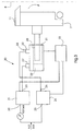
- FIG 3 shows a cutting device 20 according to the invention, which has a first three-way valve 21 with an inflow opening 22 and an outflow opening 23.
- the Cutting device 20 further comprises a second three-way valve 24 with a Inflow opening 25 and a further inflow / outflow opening 26.
- the outflow opening 23 of the first valve 21 has an inflow opening 27 of a compressed air cylinder 28 connected and receives a pressure of on the first side 29 of the compressed air cylinder 28 preferably upright between about 4.8 bar and 5.1 bar (70-75 psi).
- the An inflow / outflow opening 26 of the second valve 24 is provided with an inflow / outflow opening 30 of the Compressed air cylinder 28 connected and receives at rest on a second side 31 of Air cylinder 28 maintains a pressure of preferably about 6.2 bar (90 psi).
- the cutting element 7 Due to the pressure on the first side 29 of preferably approximately between 4.8 bar and 5.1 bar (70-75 psi), the cutting element 7 is moved from the beginning with full force onto the web 8 to be cut, since the pressure on the first side 29 is kept at the maximum over the entire period, so that no more time has to be spent for the pressure build-up, as is the case with the devices of the prior art. Overall, this results in a reduction in the time required to move the cutting element 7 and the guarantee that the knife 11 of the cutting element 7 hits the web 8 with full force. In this way, the length of the paper path that the knife 11 passes before the web is cut, and thus the risk of damage to the printing units in the case of a so-called Wicklers "significantly reduced after a web break.
- the graph shown in Fig. 4 shows the reduced time due to the increase in initial pressure to about 4.8 to 5.1 bar (70-75 psi) for cutting the web 8 through the cutting element 7 when using the device according to the invention and of the method according to the invention is required.
Landscapes
- Life Sciences & Earth Sciences (AREA)
- Forests & Forestry (AREA)
- Engineering & Computer Science (AREA)
- Mechanical Engineering (AREA)
- Folding Of Thin Sheet-Like Materials, Special Discharging Devices, And Others (AREA)
- Control Of Cutting Processes (AREA)
- Replacement Of Web Rolls (AREA)
Abstract
Description
- Fig. 1
- ein schematisches Blockdiagramm einer Schneidevorrichtung des Standes der Technik;
- Fig. 2
- ein Schaubild, das den Druckaufbau an einer Seite eines Druckluftzylinders und die Zeit bis zum Kontaktieren der Materialbahn durch das Schneideelement in einer Schneidevorrichtung des Standes der Technik aufzeigt;
- Fig. 3
- ein schematisches Blockdiagramm einer bevorzugten Ausführungsform der erfindungsgemäßen Schneidevorrichtung; und
- Fig. 4
- ein Schaubild, das den Druck in einem Druckluftzylinder und die Zeit bis zum Kontaktieren der Materialbahn aufzeigt.

- F
- = m·a (1); und
- F
- = P·A (2); wobei
- F
- = Kraft
- m
- = Masse des Schneideelements 7,
- a
- = Beschleunigung des Schneideelements 7,
- P
- = momentan verfügbarer Luftdruck,
- A
- = Fläche des Luftdruckzylinders 28,
- X
- = Schlaglänge zwischen dem Druckluftzylinder 28 und der Bahn 8
- t
- = Schlagzeit
- 1
- Schneidevorrichtung des Standes der Technik
- 2
- Vierwege-Ventil
- 3
- Druckluft-Einströmöffnung
- 4
- Druckluft-Ausströmöffnung
- 5
- Druckluft-Ein/Ausströmöffnung
- 6
- Druckluftzylinder
- 7
- Schneideelement
- 8
- Materialbahn
- 9
- erste Seite des Druckluftzylinders
- 10
- zweite Seite des Druckluftzylinders
- 11
- Messer
- 20
- erfindungsgemäße Bahnschneidevorrichtung
- 21
- erstes Dreiwege-Ventil
- 22
- Druckluft-Einströmöffnung
- 23
- Druckluft-Ausströmöffnung
- 24
- zweites Dreiwege-Ventil
- 25
- Druckluft-Einströmöffnung
- 26
- Druckluft-Ein/Ausströmöffnung
- 27
- Einströmöffnung des Druckluftzylinders
- 28
- Druckluftzylinder
- 29
- erste Seite des Druckluftzylinders
- 30
- Ein/Ausströmöffnung des Druckluftzylinders
- 31
- zweite Seite des Druckluftzylinders
- 32
- Steuerungseinheit
- 33
- Schnellausströmventil
Claims (12)
- Vorrichtung zum Schneiden von Materialbahnen, mit einem Druckluftzylinder (28) mit einer ersten Seite (29) und einer zweiten Seite (31), einem mit der ersten Seite (29) des Druckluftzylinders (28) verbundenen ersten Ventil (21), das eine erste Seite (29) des Druckluftzylinders (28) mit einem ersten vorgegebenen Druck beaufschlagt, und einem mit der zweiten Seite (24) des Druckluftzylinders (28) verbundenen zweiten Ventil (24),
dadurch gekennzeichnet,
dass das zweite Ventil (24) in einem nicht-schneidenden Zustand des Druckluftzylinders (28) die zweite Seite (31) mit einem zweiten vorgegebenen Druck beaufschlagt, der größer ist als der erste vorgegebene Druck, und dass der zweite vorgegebene Druck zur Einleitung eines Schneidevorgangs am Schneidezylinder (28) auf einen Wert unter dem ersten vorgegebenen Druck reduzierbar ist. - Vorrichtung nach Anspruch 1,
dadurch gekennzeichnet,
dass ein mit dem Druckluftzylinder (28) verbundenes und von diesem angetriebenes Schneideelement (7) zum Durchtrennen einer Materialbahn (8) vorgesehen ist. - Vorrichtung nach Anspruch 2,
dadurch gekennzeichnet,
dass das erste Ventil (21) und das zweite Ventil (24) als Dreiwege-Ventile ausgebildet sind. - Vorrichtung nach einem der vorhergehenden Ansprüche,
dadurch gekennzeichnet,
dass der erste vorgegebene Druck etwa zwischen 4,8 bar und 5,1 bar (70-75 psi), liegt und der zweite vorgegebene Druck größer oder gleich etwa 6,2 bar (90 psi) ist. - Vorrichtung nach einem der vorhergehenden Ansprüche,
dadurch gekennzeichnet,
dass zur Steuerung des ersten und zweiten vorgegebenen Drucks eine mit dem Druckluftzylinder (28) sowie mit dem ersten und zweiten Ventil (21, 24) verbundene Steuerungseinheit (32) vorgesehen ist, mittels derer der Übergang des Druckluftzylinders (28) vom nicht-schneidenden Zustand zum Schneidevorgang steuerbar ist. - Vorrichtung nach einem der Ansprüche 2 bis 5,
dadurch gekennzeichnet,
dass das Schneideelement (7) zum Durchtrennen der Bahn (8) ein Messer (11) umfasst. - Vorrichtung nach einem der vorhergehenden Ansprüche,
dadurch gekennzeichnet,
dass der Druckluftzylinder (28) zur schnellen Reduzierung des zweiten vorgegebenen Drucks auf einen Wert unter dem ersten vorgegebenen Druck ein mit der zweiten Seite (31) des Druckluftzylinders (28) verbundenes Schnellausströmventil (33) umfasst. - Verfahren zum Schneiden von Materialbahnen,
gekennzeichnet durch
die folgenden Schritte:a) Beaufschlagen einer ersten Seite (29) eines ein Schneideelement (7) antreibenden Druckluftzylinders (28) mit einem ersten vorgegebenen Druck;b) Beaufschlagen der zweiten Seite (31) des Druckluftzylinders (28) im nichtschneidenden Zustand mit einem zweiten vorgegebenen Druck, der höher ist als der erste vorgegebene Druck, wobei das Schneidelement (7) in seiner Ruhestellung verharrt, solange der zweite vorgegebene Druck größer ist als der erste vorgegebene Druck; undc) Reduzieren des zweiten vorgegebenen Drucks auf einen Wert unter dem ersten vorgegebenen Druck innerhalb kurzer Zeit zur Einleitung eines Schneidevorgangs am Druckluftzylinder (28), in der Weise, dass das Schneideelement (7) bewegt wird und die Materialbahn (8) durchtrennt. - Verfahren nach Anspruch 8,
dadurch gekennzeichnet,
dass für jeden Schneidevorgang die Schritte b) und c) wiederholt werden. - Verfahren nach Anspruch 8 oder 9,
dadurch gekennzeichnet,
dass zur Steuerung des ersten und zweiten vorgegebenen Drucks sowie des Übergangs zwischen dem Schneidevorgang und dem nicht-schneidenden Vorgang eine Steuervorrichtung (32) vorgesehen ist, die Steuersignale aussendet, die vom Druckluftzylinder (28) empfangen werden. - Verfahren nach Anspruch 10,
dadurch gekennzeichnet,
dass zur Erzeugung des ersten vorgegebenen Drucks ein erstes Ventil (21) und zur Erzeugung des zweiten vorgegebenen Drucks ein zweites Ventil (24) vorgesehen ist, und dass das erste und zweite Ventil (21, 24) mittels von der Steuerungseinheit (32) ausgesendeter Steuersignale gesteuert werden. - Verfahren nach einem der Ansprüche 8 bis 11,
dadurch gekennzeichnet,
dass zum schnellen Reduzieren des zweiten vorgegebenen Drucks in Schritt c) ein Schnellausströmventil (33) eingesetzt wird.
Applications Claiming Priority (2)
| Application Number | Priority Date | Filing Date | Title |
|---|---|---|---|
| US09/339,725 US6658972B1 (en) | 1999-06-24 | 1999-06-24 | Full force web severer |
| US339725 | 1999-06-24 |
Publications (2)
| Publication Number | Publication Date |
|---|---|
| EP1063087A1 true EP1063087A1 (de) | 2000-12-27 |
| EP1063087B1 EP1063087B1 (de) | 2002-10-23 |
Family
ID=23330324
Family Applications (1)
| Application Number | Title | Priority Date | Filing Date |
|---|---|---|---|
| EP00111002A Expired - Lifetime EP1063087B1 (de) | 1999-06-24 | 2000-05-30 | Vorrichtung und Verfahren zum Schneiden von Materialbahnen |
Country Status (4)
| Country | Link |
|---|---|
| US (1) | US6658972B1 (de) |
| EP (1) | EP1063087B1 (de) |
| JP (1) | JP2001025993A (de) |
| DE (2) | DE50000668D1 (de) |
Families Citing this family (4)
| Publication number | Priority date | Publication date | Assignee | Title |
|---|---|---|---|---|
| DE20319210U1 (de) * | 2003-12-11 | 2004-03-04 | Voith Paper Patent Gmbh | Vorrichtung zum Trennen einer Materialbahn |
| US20060174736A1 (en) * | 2005-02-10 | 2006-08-10 | Aaron Bloy | Slitter knife system and method |
| DE102006005121A1 (de) * | 2006-02-04 | 2007-08-09 | Peter Mayr | Falzwerk einer Druckmaschine mit mindestens einer Steuervorrichtung für Funktionseinheiten |
| ES2992851T3 (en) | 2019-05-24 | 2024-12-19 | Poly Clip System Gmbh & Co Kg | Cutting equipment and clipping machine |
Citations (7)
| Publication number | Priority date | Publication date | Assignee | Title |
|---|---|---|---|---|
| DE83793C (de) * | ||||
| CH565099A5 (en) * | 1973-10-05 | 1975-08-15 | Huskins Joseph P | Cutting and folding equipment for newspaper printing machine - has cutter cyclicly activated by pneumatic cylinder |
| DE3043507A1 (de) * | 1979-12-06 | 1981-06-11 | Arnold Montreal Quebec Kastner | Verfahren und vorrichtung zum herstellen von paeckchen gefalteter und ineinandergeschossener papierblaetter |
| US4699031A (en) * | 1986-02-20 | 1987-10-13 | Ametek, Inc. | Method and apparatus for automatically cutting a web of foam material into sheets and for dispensing the cut sheets |
| DE4202363A1 (de) * | 1992-01-29 | 1993-08-05 | Heidelberger Druckmasch Ag | Vorrichtung zum trennen einer auch aus mehreren teilbahnen bestehenden bahn in abschnitte |
| EP0739695A2 (de) * | 1995-04-26 | 1996-10-30 | Valmet Corporation | Vorrichtung zum Abschneiden einer Bahn |
| DE29809334U1 (de) * | 1997-06-02 | 1998-07-30 | Valmet Corp., Helsinki | Bahnschneidvorrichtung |
Family Cites Families (31)
| Publication number | Priority date | Publication date | Assignee | Title |
|---|---|---|---|---|
| US1833216A (en) * | 1925-12-14 | 1931-11-24 | Hanna Engineering Works | Rapid puncher and riveter |
| US3094043A (en) * | 1958-02-10 | 1963-06-18 | Powers Wire Products Company I | Self returning drive piston and valve therefor |
| US3170379A (en) * | 1962-02-13 | 1965-02-23 | Dempster Brothers Inc | Hydraulic system |
| US3267677A (en) * | 1963-05-09 | 1966-08-23 | Leo C Bollar | Impact forming machine |
| US3340756A (en) * | 1965-01-08 | 1967-09-12 | Yoder Co | Die accelerator |
| GB1118691A (en) * | 1965-05-18 | 1968-07-03 | Standel Ltd | Improvements in or relating to pneumatically operated reciprocating tools |
| US3735823A (en) * | 1970-05-01 | 1973-05-29 | Nippon Pneumatic Mfg | Impact motive implement |
| DE2133511A1 (de) * | 1971-07-06 | 1973-01-25 | Idra Pressen Gmbh | Verfahren und vorrichtung zum erzeugen von abguessen bestimmter gefuegebeschaffenheit auf nach dem mehrphasenprinzip arbeitenden kaltkammer-druckgiessmaschinen mit multiplikator |
| US3805652A (en) * | 1972-05-03 | 1974-04-23 | Ind Res & Eng Inc | Automatic tail cutter |
| US3796050A (en) * | 1972-05-18 | 1974-03-12 | Foster Miller Ass | High energy rate actuator |
| US3925985A (en) * | 1973-01-09 | 1975-12-16 | Rapidex Inc | Impact actuator |
| US3872934A (en) * | 1973-10-30 | 1975-03-25 | Nippon Pneumatic Mfg | Impact tool |
| FR2323478A1 (fr) * | 1975-09-10 | 1977-04-08 | Jambon Anciens Ateliers H | Presse hydraulique pour operation de cisaillage ou de tronconnage |
| DE2630278C3 (de) * | 1976-07-06 | 1980-06-12 | Dieter Haubold Industrielle Nagelgeraete, 3005 Hemmingen-Westerfeld | Druckluftnagler |
| DE2645849A1 (de) * | 1976-10-11 | 1978-04-13 | Osterwalder Ag | Hydraulisch angetriebene presse |
| US4246820A (en) * | 1978-02-08 | 1981-01-27 | Emhart Industries, Inc. | Apparatus for straight line shearing |
| US4295411A (en) * | 1979-10-03 | 1981-10-20 | Joy Manufacturing Company | Impactor |
| US4249436A (en) * | 1979-10-10 | 1981-02-10 | Natmar, Inc. | Machine and method for removing a label sewn to a workpiece |
| US4534250A (en) * | 1981-04-02 | 1985-08-13 | Garrocho Jose M | Miniature pneumatic punch |
| US4462418A (en) * | 1982-02-25 | 1984-07-31 | The Al Xander Co., Inc. | Unitized pneumatic cycling and timing system |
| US4541565A (en) * | 1983-02-28 | 1985-09-17 | Deimerly Thomas R | Air powered reciprocator |
| FI860797A7 (fi) * | 1986-02-24 | 1987-08-25 | Valmet Paper Machinery Inc | Paperirainan katkaisulaite. |
| JPH0645352Y2 (ja) * | 1987-12-02 | 1994-11-24 | 三菱重工業株式会社 | フィルム捲取機の切断刃作動装置 |
| DE3805164A1 (de) * | 1988-02-19 | 1989-08-31 | Krupp Gmbh | Schneidvorrichtung fuer harzmatten |
| US5568754A (en) * | 1993-01-14 | 1996-10-29 | Murata Machinery, Ltd. | Servo controlled right angle shear press |
| US5522212A (en) * | 1994-12-21 | 1996-06-04 | Kubik; Philip A. | Rod equal displacement cylinder in a rapid transfer and feed system |
| GB9607193D0 (en) * | 1996-04-04 | 1996-06-12 | Emhart Glass Mach Invest | Pneumatic mechanism |
| JPH10108989A (ja) * | 1996-10-08 | 1998-04-28 | Juki Corp | ミシンのテープカッター装置 |
| JP2981178B2 (ja) * | 1996-11-05 | 1999-11-22 | ユーエイチティー株式会社 | 切断加工装置 |
| US6050172A (en) * | 1997-04-04 | 2000-04-18 | Emhart Glass S.A. | Pneumatically operated mechanism |
| US6095184A (en) * | 1999-06-30 | 2000-08-01 | Mac Valves Inc. | Pressure regulator with integrated control valve, adjustable downstream pressure build and quick exhaust |
-
1999
- 1999-06-24 US US09/339,725 patent/US6658972B1/en not_active Expired - Fee Related
-
2000
- 2000-05-30 EP EP00111002A patent/EP1063087B1/de not_active Expired - Lifetime
- 2000-05-30 DE DE50000668T patent/DE50000668D1/de not_active Expired - Lifetime
- 2000-05-30 DE DE10026947A patent/DE10026947A1/de not_active Withdrawn
- 2000-06-26 JP JP2000191013A patent/JP2001025993A/ja active Pending
Patent Citations (7)
| Publication number | Priority date | Publication date | Assignee | Title |
|---|---|---|---|---|
| DE83793C (de) * | ||||
| CH565099A5 (en) * | 1973-10-05 | 1975-08-15 | Huskins Joseph P | Cutting and folding equipment for newspaper printing machine - has cutter cyclicly activated by pneumatic cylinder |
| DE3043507A1 (de) * | 1979-12-06 | 1981-06-11 | Arnold Montreal Quebec Kastner | Verfahren und vorrichtung zum herstellen von paeckchen gefalteter und ineinandergeschossener papierblaetter |
| US4699031A (en) * | 1986-02-20 | 1987-10-13 | Ametek, Inc. | Method and apparatus for automatically cutting a web of foam material into sheets and for dispensing the cut sheets |
| DE4202363A1 (de) * | 1992-01-29 | 1993-08-05 | Heidelberger Druckmasch Ag | Vorrichtung zum trennen einer auch aus mehreren teilbahnen bestehenden bahn in abschnitte |
| EP0739695A2 (de) * | 1995-04-26 | 1996-10-30 | Valmet Corporation | Vorrichtung zum Abschneiden einer Bahn |
| DE29809334U1 (de) * | 1997-06-02 | 1998-07-30 | Valmet Corp., Helsinki | Bahnschneidvorrichtung |
Also Published As
| Publication number | Publication date |
|---|---|
| DE10026947A1 (de) | 2001-02-22 |
| EP1063087B1 (de) | 2002-10-23 |
| US6658972B1 (en) | 2003-12-09 |
| JP2001025993A (ja) | 2001-01-30 |
| DE50000668D1 (de) | 2002-11-28 |
Similar Documents
| Publication | Publication Date | Title |
|---|---|---|
| DE2656242C2 (de) | Vorrichtung zum Trennen einer Faserbahn | |
| DE69430064T2 (de) | Verfahren und Vorrichtung zum Vorbereiten des Öffnens eines Bahnwickels | |
| DE2054474B2 (de) | Vorrichtung zum Ausstanzen von Ausschnitten aus Papierbahnen | |
| EP0868571B1 (de) | Trockenpartie | |
| EP1245729A1 (de) | Verfahren und Vorrichtung zum Überführen einer Bahn | |
| EP0313039B1 (de) | Verfahren und Vorrichtung zum Falzen einer Papierbahn | |
| DE102004014360B4 (de) | Sandungseinrichtung für Schienenfahrzeuge | |
| EP2386388A1 (de) | Vorrichtung zum Querperforieren oder Querschneiden von laufenden Materialbahnen | |
| EP2392408B1 (de) | Vorrichtung zum Auftragen von Leim sowie Verfahren zum Reinigen derselben | |
| DE69910151T2 (de) | Spannungsregler für Papierbahn in einer Rotationsdruckmaschine | |
| AT501246B1 (de) | Vorrichtung und verfahren zum auftrennen einer bewegten materialbahn | |
| EP1063087A1 (de) | Vorrichtung und Verfahren zum Schneiden von Materialbahnen | |
| WO2015001126A1 (de) | Verfahren und vorrichtung zum gegenseitigen anstellen von zwei zylindern in einer druckmaschine | |
| DE2522011A1 (de) | Einrichtung zum aufwickeln von bahnen aus papier, zellstoff o.dgl. | |
| EP1065313B1 (de) | Vorrichtung zum Trennen und Überführen eines Einführstreifens | |
| DE102004055734A1 (de) | Verfahren und Vorrichtung zum rechts- und linksdrehenden Aufwickeln von Materialbahnen | |
| EP2388114B1 (de) | Vorrichtung zum Querperforieren oder Querschneiden von bewegten Materialbahnen | |
| CH672304A5 (de) | ||
| DE4415316A1 (de) | Rollenwickelmaschine | |
| EP0734988A2 (de) | Verfahren und Einrichtung zum Bewegen von Punkturnadeln | |
| DE3048589C2 (de) | ||
| DE20015032U1 (de) | Rollenwickeleinrichtung | |
| EP1424441A1 (de) | Verfahren und Vorrichtung zum Überführen einer Papierbahn | |
| DE10329690B4 (de) | Verfahren zum Einführen einer Bahn, insbesondere einer Papier-oder Kartonbahn, in eine Rollenwickelvorrichtung und Rollenwickelvorrichtung | |
| DE10146538A1 (de) | Verfahren und Vorrichtung zum Überführen einer Papierbahn |
Legal Events
| Date | Code | Title | Description |
|---|---|---|---|
| PUAI | Public reference made under article 153(3) epc to a published international application that has entered the european phase |
Free format text: ORIGINAL CODE: 0009012 |
|
| 17P | Request for examination filed |
Effective date: 20001026 |
|
| AK | Designated contracting states |
Kind code of ref document: A1 Designated state(s): CH DE GB IT LI |
|
| AX | Request for extension of the european patent |
Free format text: AL;LT;LV;MK;RO;SI |
|
| 17Q | First examination report despatched |
Effective date: 20010710 |
|
| AKX | Designation fees paid |
Free format text: CH DE GB IT LI |
|
| GRAG | Despatch of communication of intention to grant |
Free format text: ORIGINAL CODE: EPIDOS AGRA |
|
| GRAG | Despatch of communication of intention to grant |
Free format text: ORIGINAL CODE: EPIDOS AGRA |
|
| GRAH | Despatch of communication of intention to grant a patent |
Free format text: ORIGINAL CODE: EPIDOS IGRA |
|
| GRAH | Despatch of communication of intention to grant a patent |
Free format text: ORIGINAL CODE: EPIDOS IGRA |
|
| GRAA | (expected) grant |
Free format text: ORIGINAL CODE: 0009210 |
|
| AK | Designated contracting states |
Kind code of ref document: B1 Designated state(s): CH DE GB IT LI |
|
| PG25 | Lapsed in a contracting state [announced via postgrant information from national office to epo] |
Ref country code: IT Free format text: LAPSE BECAUSE OF FAILURE TO SUBMIT A TRANSLATION OF THE DESCRIPTION OR TO PAY THE FEE WITHIN THE PRESCRIBED TIME-LIMIT;WARNING: LAPSES OF ITALIAN PATENTS WITH EFFECTIVE DATE BEFORE 2007 MAY HAVE OCCURRED AT ANY TIME BEFORE 2007. THE CORRECT EFFECTIVE DATE MAY BE DIFFERENT FROM THE ONE RECORDED. Effective date: 20021023 Ref country code: GB Free format text: LAPSE BECAUSE OF FAILURE TO SUBMIT A TRANSLATION OF THE DESCRIPTION OR TO PAY THE FEE WITHIN THE PRESCRIBED TIME-LIMIT Effective date: 20021023 |
|
| REG | Reference to a national code |
Ref country code: GB Ref legal event code: FG4D Free format text: NOT ENGLISH |
|
| REG | Reference to a national code |
Ref country code: CH Ref legal event code: EP |
|
| REF | Corresponds to: |
Ref document number: 50000668 Country of ref document: DE Date of ref document: 20021128 |
|
| GBV | Gb: ep patent (uk) treated as always having been void in accordance with gb section 77(7)/1977 [no translation filed] |
Effective date: 20021023 |
|
| PLBE | No opposition filed within time limit |
Free format text: ORIGINAL CODE: 0009261 |
|
| STAA | Information on the status of an ep patent application or granted ep patent |
Free format text: STATUS: NO OPPOSITION FILED WITHIN TIME LIMIT |
|
| 26N | No opposition filed |
Effective date: 20030724 |
|
| PGFP | Annual fee paid to national office [announced via postgrant information from national office to epo] |
Ref country code: CH Payment date: 20110525 Year of fee payment: 12 |
|
| PGFP | Annual fee paid to national office [announced via postgrant information from national office to epo] |
Ref country code: DE Payment date: 20110527 Year of fee payment: 12 |
|
| REG | Reference to a national code |
Ref country code: CH Ref legal event code: PL |
|
| PG25 | Lapsed in a contracting state [announced via postgrant information from national office to epo] |
Ref country code: CH Free format text: LAPSE BECAUSE OF NON-PAYMENT OF DUE FEES Effective date: 20120531 Ref country code: LI Free format text: LAPSE BECAUSE OF NON-PAYMENT OF DUE FEES Effective date: 20120531 |
|
| REG | Reference to a national code |
Ref country code: DE Ref legal event code: R119 Ref document number: 50000668 Country of ref document: DE Effective date: 20121201 |
|
| PG25 | Lapsed in a contracting state [announced via postgrant information from national office to epo] |
Ref country code: DE Free format text: LAPSE BECAUSE OF NON-PAYMENT OF DUE FEES Effective date: 20121201 |