EP1059377A1 - Absaugvorrichtung an einer Textilmaschine wie insbesondere an einer Wasservernadelungseinrichtung - Google Patents
Absaugvorrichtung an einer Textilmaschine wie insbesondere an einer Wasservernadelungseinrichtung Download PDFInfo
- Publication number
- EP1059377A1 EP1059377A1 EP00111771A EP00111771A EP1059377A1 EP 1059377 A1 EP1059377 A1 EP 1059377A1 EP 00111771 A EP00111771 A EP 00111771A EP 00111771 A EP00111771 A EP 00111771A EP 1059377 A1 EP1059377 A1 EP 1059377A1
- Authority
- EP
- European Patent Office
- Prior art keywords
- suction
- suction device
- cleaning bar
- bar
- cleaning
- Prior art date
- Legal status (The legal status is an assumption and is not a legal conclusion. Google has not performed a legal analysis and makes no representation as to the accuracy of the status listed.)
- Granted
Links
Images

Classifications
-
- D—TEXTILES; PAPER
- D04—BRAIDING; LACE-MAKING; KNITTING; TRIMMINGS; NON-WOVEN FABRICS
- D04H—MAKING TEXTILE FABRICS, e.g. FROM FIBRES OR FILAMENTARY MATERIAL; FABRICS MADE BY SUCH PROCESSES OR APPARATUS, e.g. FELTS, NON-WOVEN FABRICS; COTTON-WOOL; WADDING ; NON-WOVEN FABRICS FROM STAPLE FIBRES, FILAMENTS OR YARNS, BONDED WITH AT LEAST ONE WEB-LIKE MATERIAL DURING THEIR CONSOLIDATION
- D04H18/00—Needling machines
- D04H18/04—Needling machines with water jets
Definitions
- the invention relates in particular to a suction device for liquids on water needling machines, where the suction device outside Water bar is assigned to the generation of liquid jets, possibly existing a suction pipe with suction openings arranged over the working length of the pipe, through which the liquid is sucked off due to the negative pressure generated in the pipe is, and on both sides and parallel to the openings along the tube slide rails are arranged to support a means of transport such as drum for that needling web-like material.
- the fixed suction pipe must be used because of the Vacuum between 20 and 400 mbar be very stable.
- the Suction tube is therefore made of a thick wall into which the suction openings are drilled. Inserted laterally along an axially parallel surface line Openings are then the slide rails for the transporting drum or a belt arranged in a fixed position, which define the effective suction slot with their distance.
- the width of the suction slot depends on the transport speed the drum or the weight of the fleece or the like for optimization the suction power must be changed because the drainage process for the Needling effect is crucial. There is also a risk that the suction slot becomes clogged with fiber residues, so that regular cleaning is required.
- the invention is based, both a simple cleaning and the task at the same time to allow a quick change in the width of the suction slot.
- the invention is not limited to water needling machines, but applies for all suction devices in the textile industry for the necessary drainage of the Good.
- the suction device consists, for. B. from a liquid-permeable, rotatable gelageilen Drum 1 on which the material 2 to be needled rests.
- the drum 1 is here assigned above a water bar 3, from which the water jets 4 under high pressure exit and hit against good 2.
- the sprayed water is instant then vacuum under the goods 2.
- 1 Centrally mounted a suction pipe 5, in the wall along a surface line Suction openings 6 are introduced. Right and left of these openings 6 are parallel to the surface line radially outside the tube 5 slide strips or the like. 7, 8 for Determination of the width of the suction slot 9 arranged stationary.
- the cleaning bar 10 corresponds to the representation of FIG. 3 in the lower part the cleaning bar 10 slots 12 to the suction from the suction tube 5 full to have an effect. It is advantageous if the webs between the openings 6 in the suction pipe 5 from the webs between the openings 12 in the cleaning bar 10 are at least partially covered, so that on the webs of Cleaning strip 10 lay down the fibers and not on the webs of the suction pipe 5. This is a quick cleaning of the suction slot 9, 6 by performed outside Cleaning or quick by replacing the cleaning bar 10 possible.
- the cleaning bar 10 continues to perform the task of quickly changing the slot width of the suction slot 9 '. This is done by a separating strip 13, which is part of the cleaning strip 10 and is arranged in the upper part of the cleaning strip 10.
- the cleaning bar 10 fills the distance between the slide bars 7, 8, but the width of the separating bar 13 defines the width of the suction slot 9 . It is arranged on one side of the cleaning bar 10, here on the right, and depending on the width partially covers the elongated holes 12.
- the separating strip 13 is thus arranged eccentrically on one side in the suction slot 9 and only bears against the one sliding strip 7 with one cheek.
- the width of the suction slot 9 ' is determined with the other cheek up to the opposite flank of the slide bar 8.
- the flank of the separating strip resting on the cheek of the sliding strip 7 is to be provided on the draining side of the rotating drum 1. This prevents the possibly narrow separating strip 13 from bending.
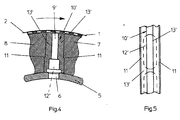
- the suction slot 9 ' is at the cleaning bar 10' each slot width radially above the suction opening 6 in the suction pipe 5
- a separating strip 13 ' is provided on each side of the suction slot 9', which on the flanks of the two slide strips 7, 8 bear. So that the suction slot 9 'is radial above the openings 12 'arranged at the bottom of the cleaning bar 10', as is the case also emerges from FIG. 5.
- This configuration of the cleaning bar 10 ' avoided Dirt corners in the area of the groove 11, which according to the execution Fig. 2 in the area of the suction slot 9 'extending into the water flow path Edge.
Landscapes
- Engineering & Computer Science (AREA)
- Textile Engineering (AREA)
- Nonwoven Fabrics (AREA)
- Treatment Of Fiber Materials (AREA)
- Cleaning In General (AREA)
Abstract
Description
- Fig. 1
- Im Querschnitt eine Walze zur hydrodynamischen Vernadelung eines Vlieses oder dgl.,
- Fig. 2
- in vergrößerter Darstellung der Absaugschlitz nach Fig. 1,
- Fig. 3
- die Draufsicht auf die Reinigungsleiste zwischen den Gleitleisten das Absaugrohres,
- Fig. 4
- eine andere Ausgestaltung des Absaugschlitzes wie die gemäß Fig. 2 und
- Fig. 5
- die Draufsicht auf die Reinigungsleiste gemäß Fig. 4.
Claims (14)
- Absaugeinrichtung für Flüssigkeiten insbesondere an Wasservernadelungsmaschinen, bei der der Absaugeinrichtung außerhalb ein Wasserbalken zur Erzeugung von Flüssigkeitsstrahlen zugeordnet ist, ggf. bestehend aus einem Absaugrohr mit über die Arbeitslänge des Rohres angeordneten Absaugöffnungen, durch die die Flüssigkeit aufgrund des im Rohr erzeugten Unterdruckes abgesaugt wird, und beidseitig und parallel zu den Öffnungen längs des Rohres Gleitleisten od. dgl. angeordnet sind zur Abstützung von einem Transportmittel wie Trommel für das zu vernadelnde bahnförmige Gut, dadurch gekennzeichnet, dass zwischen den Gleitleisten od. dgl. (7, 8) eine auswechselbare Reinigungsleiste (10, 10') angeordnet ist.
- Absaugeinrichtung nach Anspruch 1, dadurch gekennzeichnet, dass die Reinigungsleiste (10, 10') stirnseitig des Rohres (5) ein- und ausschiebbar gelagen ist.
- Absaugeinrichtung nach einem der vorhergehenden Ansprüche, dadurch gekennzeichnet, dass die Reinigungsleiste (10, 10') auf dem Absaugrohr (5) abgestützt ist.
- Absaugeinrichtung nach einem der vorhergehenden Ansprüche, dadurch gekennzeichnet, dass die Reinigungsleiste (10, 10') als Schuh ausgebildet ist, dessen breiterer Teil sich auf dem Absaugrohr (5) abstützt.
- Absaugeinrichtung nach einem der vorhergehenden Ansprüche, dadurch gekennzeichnet, dass in der Reinigungsleiste (10, 10') Durchflussöffnungen (12, 12') eingebracht sind, deren Stege die Stege der Absaugöffnungen (6) des Absaugrohres (5) abdecken.
- Absaugeinrichtung nach einem der vorhergehenden Ansprüche, dadurch gekennzeichnet, dass die Durchflussöffnungen (12, 12') der Reinigungsleiste (10, 10') als Langlöcher ausgebildet sind.
- Absaugeinrichtung nach einem der vorhergehenden Ansprüche, dadurch gekennzeichnet, dass die Durchflussöffnungen der Reinigungsleiste im Querschnitt veränderbar sind.
- Absaugeinrichtung nach einem der vorhergehenden Ansprüche, dadurch gekennzeichnet, dass die Durchflussöffnungen (12, 12') der Reinigungsleiste (10, 10') im dem dem Absaugrohr (5) zugeordneten unteren Teil angeordnet sind und der der Trommel (1) zugeordnete obere Teil in seiner Breite zur Veränderung des wirksamen Absaugschlitzes (9') veränderbar ist.
- Absaugeinrichtung nach einem der vorhergehenden Ansprüche, dadurch gekennzeichnet, dass der Abstand zwischen den beiden Gleitleisten (7, 8) od. dgl. von der Reinigungsleiste (10, 10') ausgefüllt und in dem der Trommel (1) zugeordneten oberen Teil eine die Breite des Absaugschlitzes (9') bestimmende Trennleiste (13, 13') angeordnet ist
- Absaugeinrichtung nach einem der vorhergehenden Ansprüche, dadurch gekennzeichnet, dass die Trennleiste (13, 13') im der Trommel (5) zugeordnete oberen Teil mit den Gleitleisten (7, 8) radial außerhalb fluchtet und im unteren Teil je nach der Breite der Trennleiste (13, 13') diese zumindest teilweise die Durchflussöffnungen (12, 12') der Reinigungsleiste (10, 10') abdeckt.
- Absaugeinrichtung nach einem der vorhergehenden Ansprüche, dadurch gekennzeichnet, dass die Trennleiste (13) nur auf der einen Seite der Reinigungsleiste (10) angeordnet ist und der wirksame Absaugschlitz (9') insofern durch die eine Wandung der Trennleiste (13) und durch die gegenüberliegende Wandung der Gleitleiste od. dgl. (8) gebildet ist.
- Absaugeinrichtung nach einem der vorhergehenden Ansprüche, dadurch gekennzeichnet, dass die Trennleiste (13) in Drehrichtung der Trommel (1) gesehen auf der Flanke der ablaufenden Gleitleiste (7) angeordnet ist und nur an dieser Gleitleiste (7) anliegt.
- Absaugeinrichtung nach einem der vorhergehenden Ansprüche, dadurch gekennzeichnet, dass nicht nur eine sondern zwei Trennleisten (13') die Breite des Absaugschlitzes (9') bestimmen, diese Trennleisten gleich breit sind und damit der Absaugschlitz (9') in der Mitte zwischen den beiden Gleitleisten (7, 8) angeordnet ist.
- Absaugeinrichtung nach einem der vorhergehenden Ansprüche, dadurch gekennzeichnet, dass der Absaugschlitz (9') der Reinigungsleiste (10) radial oberhalb der Absaugöffnung (6) des Absaugrohres (5) angeordnet ist.
Applications Claiming Priority (2)
| Application Number | Priority Date | Filing Date | Title |
|---|---|---|---|
| DE19925703 | 1999-06-06 | ||
| DE19925703A DE19925703A1 (de) | 1999-06-06 | 1999-06-06 | Absaugeinrichtung an einer Textilmaschine wie insbesondere Wasservernadelungsmaschine |
Publications (2)
| Publication Number | Publication Date |
|---|---|
| EP1059377A1 true EP1059377A1 (de) | 2000-12-13 |
| EP1059377B1 EP1059377B1 (de) | 2005-08-03 |
Family
ID=7910291
Family Applications (1)
| Application Number | Title | Priority Date | Filing Date |
|---|---|---|---|
| EP00111771A Expired - Lifetime EP1059377B1 (de) | 1999-06-06 | 2000-06-03 | Absaugvorrichtung an einer Textilmaschine wie insbesondere an einer Wasservernadelungseinrichtung |
Country Status (4)
| Country | Link |
|---|---|
| US (1) | US6412140B1 (de) |
| EP (1) | EP1059377B1 (de) |
| JP (1) | JP4395240B2 (de) |
| DE (2) | DE19925703A1 (de) |
Cited By (5)
| Publication number | Priority date | Publication date | Assignee | Title |
|---|---|---|---|---|
| WO2001079598A3 (de) * | 2000-04-17 | 2002-03-21 | Gerold Fleissner | Absaugeinrichtung an einer textilmaschine wie insbesondere wasservernadelungseinrichtung |
| WO2002055776A3 (de) * | 2001-01-11 | 2002-09-12 | Fleissner Maschf Gmbh Co | Absaugeinrichtung an einer textilmaschine wie insbesondere wasservernadelungseinrichtung |
| WO2005059217A1 (de) * | 2003-12-18 | 2005-06-30 | Fleissner Gmbh | Absaugvorrichtung für flüssigkeiten insbesondere an maschinen zur hydrodynamischen vernadelung |
| WO2020120412A1 (de) * | 2018-12-14 | 2020-06-18 | Autefa Solutions Germany Gmbh | Strahlsaugkasten und strahlsaugverfahren |
| EP4299810A1 (de) | 2022-06-29 | 2024-01-03 | AUTEFA Solutions Germany GmbH | Saugdüse, strahlsaugkasten und strahlsaugverfahren |
Families Citing this family (9)
| Publication number | Priority date | Publication date | Assignee | Title |
|---|---|---|---|---|
| US6511549B1 (en) * | 2001-08-17 | 2003-01-28 | Philp Morris Incorporated | Vacuum cleaning wheel and vacuum applicator |
| DE10307074A1 (de) * | 2003-02-19 | 2004-09-02 | Fleissner Gmbh & Co. Maschinenfabrik | Vorrichtung mit einer von einem Fluid radial durchströmten Siebtrommel und einem diese umgebenden durchlässigen Belag |
| DE102005055939B3 (de) * | 2005-11-24 | 2007-02-08 | Fleissner Gmbh | Düsenbalken in einer Vorrichtung zur Erzeugung von Flüssigkeitsstrahlen |
| DE102007015870B4 (de) * | 2007-04-02 | 2018-03-29 | GM Global Technology Operations LLC (n. d. Ges. d. Staates Delaware) | Kraftfahrzeug mit einer nach hinten öffnenden Tür |
| DE202010016908U1 (de) * | 2010-12-22 | 2011-12-29 | Trützschler Nonwovens Gmbh | Vorrichtung zum Reinigen eines Düsenstreifens für Wasserstrahlvernadelungsanlagen |
| CN103541154A (zh) * | 2013-10-30 | 2014-01-29 | 绍兴县庄洁无纺材料有限公司 | 一种湿态纤网主动转移转鼓装置 |
| CN107523941A (zh) * | 2017-10-17 | 2017-12-29 | 江苏金龙科技股份有限公司 | 针刺机的托网板除尘装置 |
| CN114875581B (zh) * | 2022-06-14 | 2023-02-24 | 绍兴舒洁雅无纺材料有限公司 | 一种无纺布水刺系统 |
| CN115058828B (zh) * | 2022-06-17 | 2023-12-29 | 江西美润环保制品有限公司 | 一种湿法水刺无纺布加工装置 |
Citations (4)
| Publication number | Priority date | Publication date | Assignee | Title |
|---|---|---|---|---|
| US3590453A (en) * | 1968-06-19 | 1971-07-06 | Metal Tech Inc | Honeycomb roll |
| DE4012541A1 (de) * | 1989-11-09 | 1991-06-20 | Honeycomb Systems | Vorrichtung zum einbringen von fluessigkeitsstrahlen mit hoher geschwindigkeit in eine faserfoermige bahn zur strahlverflechtung |
| US5052197A (en) * | 1989-03-08 | 1991-10-01 | Fleissner Maschinenfabrik Ag | Apparatus for flow-through treatment of textile material, paper or the like |
| US5609046A (en) * | 1994-06-28 | 1997-03-11 | Fleissner Gmbh & Co., Kg | Device for continuous treatment of textile material or the like |
Family Cites Families (3)
| Publication number | Priority date | Publication date | Assignee | Title |
|---|---|---|---|---|
| US3119140A (en) * | 1962-01-23 | 1964-01-28 | Honeywell Regulator Co | Tape cleaning device |
| US3841910A (en) * | 1970-04-13 | 1974-10-15 | Bird Machine Co | Liquid extracting apparatus and method |
| FR2731236B1 (fr) * | 1995-03-02 | 1997-04-11 | Icbt Perfojet Sa | Installation pour la realisation de nappes non tissees dont la cohesion est obtenue par l'action de jets de fluide |
-
1999
- 1999-06-06 DE DE19925703A patent/DE19925703A1/de not_active Withdrawn
-
2000
- 2000-06-03 DE DE50010862T patent/DE50010862D1/de not_active Expired - Lifetime
- 2000-06-03 EP EP00111771A patent/EP1059377B1/de not_active Expired - Lifetime
- 2000-06-05 JP JP2000167864A patent/JP4395240B2/ja not_active Expired - Fee Related
- 2000-06-06 US US09/588,001 patent/US6412140B1/en not_active Expired - Fee Related
Patent Citations (4)
| Publication number | Priority date | Publication date | Assignee | Title |
|---|---|---|---|---|
| US3590453A (en) * | 1968-06-19 | 1971-07-06 | Metal Tech Inc | Honeycomb roll |
| US5052197A (en) * | 1989-03-08 | 1991-10-01 | Fleissner Maschinenfabrik Ag | Apparatus for flow-through treatment of textile material, paper or the like |
| DE4012541A1 (de) * | 1989-11-09 | 1991-06-20 | Honeycomb Systems | Vorrichtung zum einbringen von fluessigkeitsstrahlen mit hoher geschwindigkeit in eine faserfoermige bahn zur strahlverflechtung |
| US5609046A (en) * | 1994-06-28 | 1997-03-11 | Fleissner Gmbh & Co., Kg | Device for continuous treatment of textile material or the like |
Cited By (10)
| Publication number | Priority date | Publication date | Assignee | Title |
|---|---|---|---|---|
| WO2001079598A3 (de) * | 2000-04-17 | 2002-03-21 | Gerold Fleissner | Absaugeinrichtung an einer textilmaschine wie insbesondere wasservernadelungseinrichtung |
| WO2002055776A3 (de) * | 2001-01-11 | 2002-09-12 | Fleissner Maschf Gmbh Co | Absaugeinrichtung an einer textilmaschine wie insbesondere wasservernadelungseinrichtung |
| US7188631B2 (en) | 2001-01-11 | 2007-03-13 | Fleissner Gmbh & Co. Maschinenfabrik | Suction device on a textile machine, especially a water needling device |
| WO2005059217A1 (de) * | 2003-12-18 | 2005-06-30 | Fleissner Gmbh | Absaugvorrichtung für flüssigkeiten insbesondere an maschinen zur hydrodynamischen vernadelung |
| WO2020120412A1 (de) * | 2018-12-14 | 2020-06-18 | Autefa Solutions Germany Gmbh | Strahlsaugkasten und strahlsaugverfahren |
| CN113166998A (zh) * | 2018-12-14 | 2021-07-23 | 奥特发德国科技有限公司 | 射流抽吸箱和射流抽吸方法 |
| CN113166998B (zh) * | 2018-12-14 | 2023-02-28 | 奥特发德国科技有限公司 | 射流抽吸箱和射流抽吸方法 |
| US11767624B2 (en) | 2018-12-14 | 2023-09-26 | Autefa Solutions Germany Gmbh | Jet suction box and jet suction process |
| EP4299810A1 (de) | 2022-06-29 | 2024-01-03 | AUTEFA Solutions Germany GmbH | Saugdüse, strahlsaugkasten und strahlsaugverfahren |
| US12473675B2 (en) | 2022-06-29 | 2025-11-18 | Autefa Solutions Germany Gmbh | Suction nozzle, jet suction box and jet suction method |
Also Published As
| Publication number | Publication date |
|---|---|
| EP1059377B1 (de) | 2005-08-03 |
| DE50010862D1 (de) | 2005-09-08 |
| DE19925703A1 (de) | 2000-12-07 |
| JP2001020172A (ja) | 2001-01-23 |
| JP4395240B2 (ja) | 2010-01-06 |
| US6412140B1 (en) | 2002-07-02 |
Similar Documents
| Publication | Publication Date | Title |
|---|---|---|
| EP1001064B1 (de) | Vorrichtung zur Herstellung von perforierten Vliesstoffen mittels hydrodynamischer Vernadelung | |
| EP1059377A1 (de) | Absaugvorrichtung an einer Textilmaschine wie insbesondere an einer Wasservernadelungseinrichtung | |
| EP0818568A2 (de) | Verfahren und Vorrichtung zum hydrodynamischen Verschlingen der Fasern einer Faserbahn | |
| DE2827495C2 (de) | ||
| DE19640750B4 (de) | Vorrichtung zum Nadeln eines Vlieses | |
| EP0358136B1 (de) | Verfahren und Vorrichtung zum Behandeln von textilen Warenbahnen | |
| DE29503752U1 (de) | Reinigungsvorrichtung | |
| DE1710477C3 (de) | Vorrichtung zum Breitveredeln von bahnförmigem Textilgut | |
| DE10018920A1 (de) | Absaugeinrichtung an einer Textilmaschine wie insbesondere Wasservernadelungseinrichtung | |
| EP1884588A2 (de) | Reinigungsvorrichtung | |
| DE19700503A1 (de) | Absaugvorrichtung und Vorrichtung zur Behandlung von textilen Flächengebilden | |
| EP0753357B1 (de) | Vorrichtung zum Aufbringen eines über die Arbeitsbreite gleichmässig dünnen Flüssigkeitsfilmes auf eine Warenbahn | |
| DE19782108B4 (de) | Verfahren zum Entfernen von Staub in der Schneidepartie einer Zellstofftrockenmaschine und Vorrichtung zur Durchführung des Verfahrens | |
| EP3421654A1 (de) | Vorrichtung mit zumindest einer teilchen- und/oder fasererzeugungseinrichtung und mit zumindest einem endlos-band | |
| DE102005034144B3 (de) | Nadelmaschine mit Einrichtungen zur Luftführung | |
| DE102017110189B4 (de) | Rollstangeneinlaufwerk für einen Endlos-Rollstangenteppich einer kontinuierlich arbeitenden Presse, Rollstangenteppichvorrichtung, Presse und Verfahren zur Führung eines Endlos-Rollstangenteppichs | |
| DE3048464A1 (de) | Absauganlage an den streckwerken einer spinnmaschine | |
| AT398031B (de) | Vorrichtung zur reinigung von textilen lamellen für jalousien oder dergleichen | |
| DE102017110199B3 (de) | Rollstangeneinlaufwerk für einen Endlos-Rollstangenteppich einer kontinuierlich arbeitenden Presse, Rollstangenteppichvorrichtung, Presse und Verfahren zur Führung eines Endlos-Rollstangenteppichs | |
| DE3037445C2 (de) | Nadelstabstreckwerk für Faserbänder | |
| EP0999305A2 (de) | Vorrichtung zur Behandlung einer Materialbahn | |
| WO2003083192A1 (de) | Pneumatische verdichtungseinrichtung für einen faserverband und verfahren zum pneumatischen verdichten eines faserverbandes | |
| DE69517098T2 (de) | Gleitführung und Antrieb für Kardenwanderdeckel | |
| DE2643611B1 (de) | Giessmaschine zum Auftragen eines fluessigen Behandlungsmittels auf flaechenhafte Werkstuecke,insbesondere Leder- und Kunststoffstuecke | |
| EP0945545A2 (de) | Saugvorrichtung |
Legal Events
| Date | Code | Title | Description |
|---|---|---|---|
| PUAI | Public reference made under article 153(3) epc to a published international application that has entered the european phase |
Free format text: ORIGINAL CODE: 0009012 |
|
| AK | Designated contracting states |
Kind code of ref document: A1 Designated state(s): CH DE FR GB IT LI |
|
| AX | Request for extension of the european patent |
Free format text: AL;LT;LV;MK;RO;SI |
|
| 17P | Request for examination filed |
Effective date: 20001102 |
|
| AKX | Designation fees paid |
Free format text: CH DE FR GB IT LI |
|
| RAP1 | Party data changed (applicant data changed or rights of an application transferred) |
Owner name: FLEISSNER GMBH & CO. MASCHINENFABRIK |
|
| RIN1 | Information on inventor provided before grant (corrected) |
Inventor name: FLEISSNER GMBH & CO. MASCHINENFABRIK |
|
| RIN1 | Information on inventor provided before grant (corrected) |
Inventor name: FLEISSNER, GEROLD |
|
| RAP1 | Party data changed (applicant data changed or rights of an application transferred) |
Owner name: FLEISSNER GMBH |
|
| 17Q | First examination report despatched |
Effective date: 20050121 |
|
| GRAP | Despatch of communication of intention to grant a patent |
Free format text: ORIGINAL CODE: EPIDOSNIGR1 |
|
| GRAS | Grant fee paid |
Free format text: ORIGINAL CODE: EPIDOSNIGR3 |
|
| GRAA | (expected) grant |
Free format text: ORIGINAL CODE: 0009210 |
|
| AK | Designated contracting states |
Kind code of ref document: B1 Designated state(s): CH DE FR GB IT LI |
|
| REG | Reference to a national code |
Ref country code: GB Ref legal event code: FG4D Free format text: NOT ENGLISH |
|
| REG | Reference to a national code |
Ref country code: CH Ref legal event code: EP |
|
| REF | Corresponds to: |
Ref document number: 50010862 Country of ref document: DE Date of ref document: 20050908 Kind code of ref document: P |
|
| GBT | Gb: translation of ep patent filed (gb section 77(6)(a)/1977) |
Effective date: 20051108 |
|
| ET | Fr: translation filed | ||
| PLBE | No opposition filed within time limit |
Free format text: ORIGINAL CODE: 0009261 |
|
| STAA | Information on the status of an ep patent application or granted ep patent |
Free format text: STATUS: NO OPPOSITION FILED WITHIN TIME LIMIT |
|
| 26N | No opposition filed |
Effective date: 20060504 |
|
| PGFP | Annual fee paid to national office [announced via postgrant information from national office to epo] |
Ref country code: CH Payment date: 20080627 Year of fee payment: 9 |
|
| PGFP | Annual fee paid to national office [announced via postgrant information from national office to epo] |
Ref country code: GB Payment date: 20080630 Year of fee payment: 9 |
|
| REG | Reference to a national code |
Ref country code: CH Ref legal event code: PL |
|
| GBPC | Gb: european patent ceased through non-payment of renewal fee |
Effective date: 20090603 |
|
| PG25 | Lapsed in a contracting state [announced via postgrant information from national office to epo] |
Ref country code: LI Free format text: LAPSE BECAUSE OF NON-PAYMENT OF DUE FEES Effective date: 20090630 Ref country code: CH Free format text: LAPSE BECAUSE OF NON-PAYMENT OF DUE FEES Effective date: 20090630 |
|
| PG25 | Lapsed in a contracting state [announced via postgrant information from national office to epo] |
Ref country code: GB Free format text: LAPSE BECAUSE OF NON-PAYMENT OF DUE FEES Effective date: 20090603 |
|
| PGFP | Annual fee paid to national office [announced via postgrant information from national office to epo] |
Ref country code: IT Payment date: 20120621 Year of fee payment: 13 |
|
| PG25 | Lapsed in a contracting state [announced via postgrant information from national office to epo] |
Ref country code: IT Free format text: LAPSE BECAUSE OF NON-PAYMENT OF DUE FEES Effective date: 20130603 |
|
| REG | Reference to a national code |
Ref country code: FR Ref legal event code: PLFP Year of fee payment: 17 |
|
| REG | Reference to a national code |
Ref country code: FR Ref legal event code: PLFP Year of fee payment: 18 |
|
| REG | Reference to a national code |
Ref country code: FR Ref legal event code: PLFP Year of fee payment: 19 |
|
| PGFP | Annual fee paid to national office [announced via postgrant information from national office to epo] |
Ref country code: DE Payment date: 20190619 Year of fee payment: 20 |
|
| PGFP | Annual fee paid to national office [announced via postgrant information from national office to epo] |
Ref country code: FR Payment date: 20190619 Year of fee payment: 20 |