EP1050716B1 - Glühkerze und Verfahren zur Herstellung derselben - Google Patents
Glühkerze und Verfahren zur Herstellung derselben Download PDFInfo
- Publication number
- EP1050716B1 EP1050716B1 EP00108176A EP00108176A EP1050716B1 EP 1050716 B1 EP1050716 B1 EP 1050716B1 EP 00108176 A EP00108176 A EP 00108176A EP 00108176 A EP00108176 A EP 00108176A EP 1050716 B1 EP1050716 B1 EP 1050716B1
- Authority
- EP
- European Patent Office
- Prior art keywords
- glow plug
- heating rod
- plug body
- electrically insulating
- region
- Prior art date
- Legal status (The legal status is an assumption and is not a legal conclusion. Google has not performed a legal analysis and makes no representation as to the accuracy of the status listed.)
- Expired - Lifetime
Links
- 238000004519 manufacturing process Methods 0.000 title claims abstract description 14
- 238000010438 heat treatment Methods 0.000 claims abstract description 84
- 239000000463 material Substances 0.000 claims abstract description 15
- 238000009413 insulation Methods 0.000 claims abstract description 13
- 239000011248 coating agent Substances 0.000 claims abstract description 4
- 238000000576 coating method Methods 0.000 claims abstract description 4
- 239000004033 plastic Substances 0.000 claims description 18
- 229920003023 plastic Polymers 0.000 claims description 18
- 239000000919 ceramic Substances 0.000 claims description 8
- 238000000034 method Methods 0.000 claims description 7
- 238000002485 combustion reaction Methods 0.000 claims description 6
- 238000007789 sealing Methods 0.000 claims description 5
- 239000004071 soot Substances 0.000 claims description 4
- 230000003197 catalytic effect Effects 0.000 claims description 3
- 230000015572 biosynthetic process Effects 0.000 claims description 2
- 238000003466 welding Methods 0.000 claims description 2
- 239000012777 electrically insulating material Substances 0.000 claims 1
- 239000007788 liquid Substances 0.000 claims 1
- 239000000843 powder Substances 0.000 claims 1
- 229920002994 synthetic fiber Polymers 0.000 abstract 1
- 229910052751 metal Inorganic materials 0.000 description 7
- 239000002184 metal Substances 0.000 description 7
- 238000005259 measurement Methods 0.000 description 4
- KDLHZDBZIXYQEI-UHFFFAOYSA-N Palladium Chemical compound [Pd] KDLHZDBZIXYQEI-UHFFFAOYSA-N 0.000 description 2
- 238000005524 ceramic coating Methods 0.000 description 2
- 150000001875 compounds Chemical class 0.000 description 2
- 230000005684 electric field Effects 0.000 description 2
- 239000011521 glass Substances 0.000 description 2
- 239000000156 glass melt Substances 0.000 description 2
- 239000003779 heat-resistant material Substances 0.000 description 2
- 239000011810 insulating material Substances 0.000 description 2
- BASFCYQUMIYNBI-UHFFFAOYSA-N platinum Chemical compound [Pt] BASFCYQUMIYNBI-UHFFFAOYSA-N 0.000 description 2
- 238000003825 pressing Methods 0.000 description 2
- 229920001169 thermoplastic Polymers 0.000 description 2
- 239000004416 thermosoftening plastic Substances 0.000 description 2
- OKTJSMMVPCPJKN-UHFFFAOYSA-N Carbon Chemical compound [C] OKTJSMMVPCPJKN-UHFFFAOYSA-N 0.000 description 1
- 239000004809 Teflon Substances 0.000 description 1
- 229920006362 Teflon® Polymers 0.000 description 1
- 229910045601 alloy Inorganic materials 0.000 description 1
- 239000000956 alloy Substances 0.000 description 1
- 230000009286 beneficial effect Effects 0.000 description 1
- 239000004566 building material Substances 0.000 description 1
- 229910010293 ceramic material Inorganic materials 0.000 description 1
- 238000010276 construction Methods 0.000 description 1
- 238000010292 electrical insulation Methods 0.000 description 1
- 229910002804 graphite Inorganic materials 0.000 description 1
- 239000010439 graphite Substances 0.000 description 1
- 238000002347 injection Methods 0.000 description 1
- 239000007924 injection Substances 0.000 description 1
- 238000002955 isolation Methods 0.000 description 1
- 229910052763 palladium Inorganic materials 0.000 description 1
- 229910052697 platinum Inorganic materials 0.000 description 1
- 229920003223 poly(pyromellitimide-1,4-diphenyl ether) Polymers 0.000 description 1
- 239000011347 resin Substances 0.000 description 1
- 229920005989 resin Polymers 0.000 description 1
- 238000007493 shaping process Methods 0.000 description 1
- 229920001187 thermosetting polymer Polymers 0.000 description 1
Images







Classifications
-
- F—MECHANICAL ENGINEERING; LIGHTING; HEATING; WEAPONS; BLASTING
- F23—COMBUSTION APPARATUS; COMBUSTION PROCESSES
- F23Q—IGNITION; EXTINGUISHING-DEVICES
- F23Q7/00—Incandescent ignition; Igniters using electrically-produced heat, e.g. lighters for cigarettes; Electrically-heated glowing plugs
- F23Q7/001—Glowing plugs for internal-combustion engines
-
- F—MECHANICAL ENGINEERING; LIGHTING; HEATING; WEAPONS; BLASTING
- F02—COMBUSTION ENGINES; HOT-GAS OR COMBUSTION-PRODUCT ENGINE PLANTS
- F02P—IGNITION, OTHER THAN COMPRESSION IGNITION, FOR INTERNAL-COMBUSTION ENGINES; TESTING OF IGNITION TIMING IN COMPRESSION-IGNITION ENGINES
- F02P19/00—Incandescent ignition, e.g. during starting of internal combustion engines; Combination of incandescent and spark ignition
- F02P19/02—Incandescent ignition, e.g. during starting of internal combustion engines; Combination of incandescent and spark ignition electric, e.g. layout of circuits of apparatus having glowing plugs
- F02P19/028—Incandescent ignition, e.g. during starting of internal combustion engines; Combination of incandescent and spark ignition electric, e.g. layout of circuits of apparatus having glowing plugs the glow plug being combined with or used as a sensor
-
- F—MECHANICAL ENGINEERING; LIGHTING; HEATING; WEAPONS; BLASTING
- F23—COMBUSTION APPARATUS; COMBUSTION PROCESSES
- F23Q—IGNITION; EXTINGUISHING-DEVICES
- F23Q7/00—Incandescent ignition; Igniters using electrically-produced heat, e.g. lighters for cigarettes; Electrically-heated glowing plugs
- F23Q7/001—Glowing plugs for internal-combustion engines
- F23Q2007/002—Glowing plugs for internal-combustion engines with sensing means
-
- F—MECHANICAL ENGINEERING; LIGHTING; HEATING; WEAPONS; BLASTING
- F23—COMBUSTION APPARATUS; COMBUSTION PROCESSES
- F23Q—IGNITION; EXTINGUISHING-DEVICES
- F23Q7/00—Incandescent ignition; Igniters using electrically-produced heat, e.g. lighters for cigarettes; Electrically-heated glowing plugs
- F23Q7/001—Glowing plugs for internal-combustion engines
- F23Q2007/004—Manufacturing or assembling methods
-
- F—MECHANICAL ENGINEERING; LIGHTING; HEATING; WEAPONS; BLASTING
- F23—COMBUSTION APPARATUS; COMBUSTION PROCESSES
- F23Q—IGNITION; EXTINGUISHING-DEVICES
- F23Q7/00—Incandescent ignition; Igniters using electrically-produced heat, e.g. lighters for cigarettes; Electrically-heated glowing plugs
- F23Q7/001—Glowing plugs for internal-combustion engines
- F23Q2007/004—Manufacturing or assembling methods
- F23Q2007/007—Manufacturing or assembling methods ion current sensors
Definitions
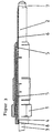
- the plastic in the contact area to the body 1 Heating rod 2 or on the inner wall of the heating rod bore in Body 1 are applied, whereupon heating element 2 and Body 1 by reducing, pressing in or pulling together be firmly connected. It can also be beneficial be to cover the sealing seat 1a with the insulation 5, so that the insulation 5 after installing the candle additionally is fixed between candle body 1 and cylinder head.
- the Insulation 5 consists of temperature-resistant Plastic with good sealing properties such as Teflon or Vespel.
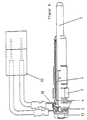
- Figure 5 gives another embodiment of the invention again, being a partial, electrically insulating ceramic coating 7 on the exiting from the body 1 Range of the heating rod 2 to, for example, about 5 mm is applied below its head end; this head area, which represents the actual ignition range by covering during coating of coating be kept free.
- This creates a defined ion current electrode formed in the head area of the heating element 2, which together with the counter electrode, which is usually the
- the mass of the connected cylinder head is a defined one electric field forms in its sphere of influence Ion current can be detected.
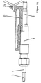
- This "shaping" of the electrical Field can be attached by, for example, a formed as a ring shaped body 10, the head of the heating element 2 is supported.
- an overmolding can also be used as an integral overmolding of the front area of the heating element 2 his.
Landscapes
- Engineering & Computer Science (AREA)
- Chemical & Material Sciences (AREA)
- Combustion & Propulsion (AREA)
- Mechanical Engineering (AREA)
- General Engineering & Computer Science (AREA)
- Resistance Heating (AREA)
- Ignition Installations For Internal Combustion Engines (AREA)
- Spark Plugs (AREA)
Description
Claims (12)
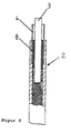
- Glühkerze mit einem Glühkerzenkörper (1) und einem im Glühkerzenkörper (1) angeordneten Heizstab (2), in den ein Innenpol (3) mit Heiz- und gegebenenfalls Regelelementen führt und dessen gegenüber dem Glühkerzenkörper (1) elektrisch isolierte Wandung den Außenpol (4) bildet, alternativ bildet ein Kontaktrohr (4) auf dem Heizstab (2), welcher gegenüber dem Glühkerzenkörper (1) isoliert ist, den Außenpol, wobei der Heizstab (2) oder der Kontaktrohr (4) mit einem elektrisch isolierenden Kunststoffmaterial (5) umgeben ist.
- Glühkerze nach Anspruch 1, dadurch gekennzeichnet, dass das elektrisch isolierende Kunststoffmaterial, das den Heizstab (2) umgibt, den Glühkerzenkörper (1) bildet.
- Glühkerze nach Anspruch 1, dadurch gekennzeichnet, dass das elektrisch isolierende Kunststoffmaterial, das den Heizstab (2) umgibt, eine Schicht (5) bildet, die zwischen dem Heizstab (2) und dem Glühkerzenkörper (1) verläuft.
- Glühkerze nach Anspruch 1, 2 oder 3, dadurch gekennzeichnet, dass im anschlussseitigen Bereich der elektrische Anschluss an die Wandung des Heizstabes (2) durch einen Rohrabschnitt (4) des Kontaktrohrs erfolgt, dessen eines Ende in einer angepassten Ausbohrung im Endbereich der Heizstabwandung angeordnet ist, wobei ein O-Ring (8) den Innenraum des Heizstabes (2) abdichtet und gleichzeitig das Kontaktrohr (4) gegen den Innenpol (3) elektrisch isoliert.
- Glühkerze nach Anspruch 1, 2 oder 3, dadurch gekennzeichnet, dass im anschlussseitigen Endbereich des Heizstabes (2) das Kontaktrohr (4) beispielsweise durch Punktschweißung fixiert ist, das gegenüber dem sich durch das Kontaktrohr erstreckenden Innenpol durch eingebrachtes elektrisch isolierendes Material (11) elektrisch isoliert ist, wobei ggf. ein O-Ring (8) zur Abdichtung des Innenraumes des Heizstabes (2) und zur elektrisch isolierenden Positionierung des Innenpols (3) vorgesehen ist.
- Glühkerze nach einem der vorhergehenden Ansprüche, dadurch gekennzeichnet, dass eine separate Ionenstrommesshülse (6) konzentrisch um den in den Brennraum ragenden Bereich des Heizstabes (2) vorgesehen ist, die sowohl gegen den Körper (1) als auch gegen den Heizstab (2) isoliert ist, wobei die Isolierung gegen den Heizstab (2) auf dem Anlagebereich der Ionenstrommesshülse (6) am Heizstab (2) als Beschichtung aus dem hitzebeständigem, elektrisch isolierendem Kunststoffmaterial ausgebildet ist.
- Glühkerze nach einem der vorhergehenden Ansprüche, dadurch gekennzeichnet, dass der in den Brennraum ragende Bereich des Heizstabes (2), ausschließlich der Heizstabspitze als Zündbereich, mit einem hitzebeständigen, elektrisch isolierenden Kunststoff- oder Keramikmaterial (7), beschichtet ist.
- Glühkerze nach einem der vorhergehenden Ansprüche, dadurch gekennzeichnet, dass der in den Brennraum ragende. Bereich des Heizstabes (2), ausschließlich der Heizstabspitze als Zündbereich, mit einer Schicht (20) versehen ist, die katalytisches Material zur Verhinderung der Bildung einer Rußschicht enthält oder daraus besteht.
- Verfahren zum Herstellen einer Glühkerze mit einem Glühkerzenkörper und einem im Glühkerzenkörper angeordneten Heizstab nach Anspruch 1, 2 oder 3, dadurch gekennzeichnet, dass der Heizstab mit dem elektrisch isolierenden Kunststoffmaterial umspritzt wird.
- Verfahren zum Herstellen einer Glühkerze mit einem Glühkerzenkörper und einem im Glühkerzenkörper angeordneten Heizstab nach Anspruch 1 oder 2, dadurch gekennzeichnet, dass der Heizstab (2) in einen vorgefertigten Kunststoffkörper eingepresst wird.
- Verfahren zum Herstellen einer Glühkerze mit einem Glühkerzenkörper und einem im Glühkerzenkörper angeordneten Heizstab nach Anspruch 3, dadurch gekennzeichnet, dass in den Ringspalt zwischen dem Heizstab (2) und dem Glühkerzenkörper (1) ein elektrisch isolierender Kunststoff eingebracht wird.
- Verfahren nach Anspruch 11, dadurch gekennzeichnet, dass der Kunststoff in flüssiger oder pulverförmiger Form eingebracht und ausgehärtet wird.
Applications Claiming Priority (2)
| Application Number | Priority Date | Filing Date | Title |
|---|---|---|---|
| DE19920758A DE19920758C1 (de) | 1999-05-05 | 1999-05-05 | Glühkerze und Verfahren zur Herstellung derselben |
| DE19920758 | 1999-05-05 |
Publications (2)
| Publication Number | Publication Date |
|---|---|
| EP1050716A1 EP1050716A1 (de) | 2000-11-08 |
| EP1050716B1 true EP1050716B1 (de) | 2003-08-13 |
Family
ID=7907106
Family Applications (1)
| Application Number | Title | Priority Date | Filing Date |
|---|---|---|---|
| EP00108176A Expired - Lifetime EP1050716B1 (de) | 1999-05-05 | 2000-04-13 | Glühkerze und Verfahren zur Herstellung derselben |
Country Status (7)
| Country | Link |
|---|---|
| US (1) | US6255626B1 (de) |
| EP (1) | EP1050716B1 (de) |
| JP (1) | JP2000337633A (de) |
| KR (1) | KR100708292B1 (de) |
| AT (1) | ATE247257T1 (de) |
| DE (2) | DE19920758C1 (de) |
| ES (1) | ES2204391T3 (de) |
Families Citing this family (12)
| Publication number | Priority date | Publication date | Assignee | Title |
|---|---|---|---|---|
| DE19920766C1 (de) * | 1999-05-05 | 2000-12-21 | Beru Ag | Glühkerze und Verfahren zur Herstellung derselben |
| DE10117641C2 (de) * | 2001-04-09 | 2003-02-27 | Beru Ag | Stabglühkerze |
| DE10128656A1 (de) * | 2001-06-15 | 2003-01-02 | Beru Ag | Stabglühkerze und Verfahren zu ihrer Herstellung |
| DE10136596B4 (de) * | 2001-07-30 | 2005-09-15 | Beru Ag | Verfahren zur Verbindung eines stabförmigen Heizelements mit einem rohrförmigen Gehäuse einer Glühkerze und durch dieses Verfahren hergestellte Glühkerze |
| DE10249706A1 (de) * | 2002-10-25 | 2004-05-13 | Robert Bosch Gmbh | Gehäuse für Glühstiftkerzen aus Kunststoff |
| DE10322129A1 (de) * | 2003-05-16 | 2004-12-02 | Robert Bosch Gmbh | Glühstiftkerze mit besonders eingebettetem Kontaktelement |
| FR2869390B1 (fr) | 2004-04-27 | 2006-07-14 | Siemens Vdo Automotive Sas | Corps d'une bougie de prechauffage comprenant un capteur de pression |
| FR2869392B1 (fr) * | 2004-04-27 | 2006-07-14 | Siemens Vdo Automotive Sas | Tete d'une bougie de prechauffage equipee d'un capteur de pression |
| EP1637806B1 (de) * | 2004-09-15 | 2012-02-01 | Beru AG | Druckmessglühkerze für einen Dieselmotor |
| DE102005024622B4 (de) * | 2005-05-30 | 2007-10-04 | Beru Ag | Stabglühkerze |
| DE102005061879A1 (de) * | 2005-12-23 | 2007-07-05 | Robert Bosch Gmbh | Glühstiftkerze |
| DE102016114929B4 (de) * | 2016-08-11 | 2018-05-09 | Borgwarner Ludwigsburg Gmbh | Druckmessglühkerze |
Family Cites Families (19)
| Publication number | Priority date | Publication date | Assignee | Title |
|---|---|---|---|---|
| JPS58115223A (ja) * | 1981-12-28 | 1983-07-08 | Ngk Spark Plug Co Ltd | 二線式グロ−プラグ |
| JPS58117924A (ja) * | 1981-12-28 | 1983-07-13 | Ngk Spark Plug Co Ltd | 二線式グロ−プラグ |
| JPS58119047U (ja) * | 1981-12-28 | 1983-08-13 | 日本特殊陶業株式会社 | 二線式グロ−プラグ |
| JPS58138923A (ja) * | 1982-02-12 | 1983-08-18 | Ngk Spark Plug Co Ltd | 二線式グロ−プラグ |
| JPS58138928A (ja) | 1982-02-12 | 1983-08-18 | Sharp Corp | オ−ブンレンジ |
| US4475029A (en) * | 1982-03-02 | 1984-10-02 | Nippondenso Co., Ltd. | Ceramic heater |
| JPS59167635A (ja) * | 1983-03-15 | 1984-09-21 | Toyota Motor Corp | デイ−ゼルエンジンのグロ−プラグ |
| JPS60165681U (ja) * | 1984-04-12 | 1985-11-02 | 日本特殊陶業株式会社 | 二線式セラミツクグロ−プラグ |
| DE8427789U1 (de) * | 1984-09-21 | 1986-01-23 | Robert Bosch Gmbh, 7000 Stuttgart | Glühstiftkerze für Brennkraftmaschinen |
| DE3511086A1 (de) * | 1985-03-27 | 1986-10-09 | Belzer-Dowidat Gmbh Werkzeug-Union, 5600 Wuppertal | Zange |
| DE3713532C2 (de) * | 1987-04-22 | 1995-09-07 | Ngk Spark Plug Co | Glühkerze |
| JP2712198B2 (ja) * | 1987-10-14 | 1998-02-10 | 株式会社デンソー | ディーゼル機関予熱栓用抵抗装置 |
| JP2752649B2 (ja) * | 1988-09-09 | 1998-05-18 | 日本特殊陶業株式会社 | セラミックヒータ |
| JPH0432615A (ja) * | 1990-05-28 | 1992-02-04 | Hitachi Metals Ltd | ディーゼルエンジン用グロープラグ |
| JPH06265144A (ja) * | 1993-03-11 | 1994-09-20 | Nippondenso Co Ltd | セラミックグロープラグ |
| JPH0742940A (ja) * | 1993-07-29 | 1995-02-10 | Nippondenso Co Ltd | セラミックグロープラグ |
| JP3207335B2 (ja) * | 1995-07-31 | 2001-09-10 | 日本特殊陶業株式会社 | グロープラグ |
| JP3834889B2 (ja) * | 1996-09-18 | 2006-10-18 | 株式会社デンソー | グロープラグ |
| JP3605965B2 (ja) * | 1996-09-12 | 2004-12-22 | 株式会社デンソー | グロープラグ |
-
1999
- 1999-05-05 DE DE19920758A patent/DE19920758C1/de not_active Expired - Fee Related
-
2000
- 2000-04-13 EP EP00108176A patent/EP1050716B1/de not_active Expired - Lifetime
- 2000-04-13 AT AT00108176T patent/ATE247257T1/de not_active IP Right Cessation
- 2000-04-13 ES ES00108176T patent/ES2204391T3/es not_active Expired - Lifetime
- 2000-04-13 DE DE50003242T patent/DE50003242D1/de not_active Expired - Lifetime
- 2000-05-03 KR KR1020000023793A patent/KR100708292B1/ko not_active Expired - Fee Related
- 2000-05-05 US US09/565,475 patent/US6255626B1/en not_active Expired - Lifetime
- 2000-05-08 JP JP2000134139A patent/JP2000337633A/ja active Pending
Non-Patent Citations (1)
| Title |
|---|
| BOVENKERK, ET AL.: "Fachkunde Metall", 1987, VERLAG EUROPA-LEHRMITTEL, WUPPERTAL * |
Also Published As
| Publication number | Publication date |
|---|---|
| DE50003242D1 (de) | 2003-09-18 |
| ATE247257T1 (de) | 2003-08-15 |
| US6255626B1 (en) | 2001-07-03 |
| KR100708292B1 (ko) | 2007-04-16 |
| DE19920758C1 (de) | 2000-12-21 |
| EP1050716A1 (de) | 2000-11-08 |
| KR20000077150A (ko) | 2000-12-26 |
| JP2000337633A (ja) | 2000-12-08 |
| ES2204391T3 (es) | 2004-05-01 |
Similar Documents
| Publication | Publication Date | Title |
|---|---|---|
| DE3010591C2 (de) | ||
| DE102009056057B4 (de) | Glühkerze und Verfahren zu ihrer Herstellung | |
| DE10212908B4 (de) | Temperatursensor und Herstellungsverfahren dafür | |
| DE102006016566B4 (de) | Zusammengesetzter Leiter, insbesondere für Glühkerzen für Dieselmotoren | |
| DE69819583T2 (de) | Keramischer Heizer | |
| DE19920758C1 (de) | Glühkerze und Verfahren zur Herstellung derselben | |
| EP1065446B2 (de) | Keramischer Heizstab und diesen enthaltende Glühkerze und Verfahren zu deren Herstellung | |
| DE10112781A1 (de) | Glühkerze und Verfahren zum Herstellen derselben | |
| DE19920766C1 (de) | Glühkerze und Verfahren zur Herstellung derselben | |
| WO2016116385A1 (de) | Glühstiftkerze | |
| EP1463910A1 (de) | Stiftheizer | |
| DE10117641C2 (de) | Stabglühkerze | |
| DE19852785A1 (de) | Keramische Glühstiftkerze | |
| EP0821200B1 (de) | Stabflammglühkerze | |
| DE69932684T2 (de) | Keramische Spitze für Glühsensor | |
| EP1240461B1 (de) | Glühstiftkerze | |
| DE19844347A1 (de) | Keramische Glühstiftkerze | |
| DE10155230C5 (de) | Stiftheizer in einer Glühstiftkerze und Glühstiftkerze | |
| DE10154641A1 (de) | Elektronisch beheizbare Glühkerze und Verfahren zur Herstellung einer elektrisch beheizbaren Glühkerze | |
| EP1267125B1 (de) | Stabglühkerze und Verfahren zu ihrer Herstellung | |
| DE10130488B4 (de) | Glühkerze | |
| EP3189273A1 (de) | Glühkerze | |
| DE10249706A1 (de) | Gehäuse für Glühstiftkerzen aus Kunststoff | |
| WO2012072313A1 (de) | Zündspule | |
| EP0263838A1 (de) | Glühstiftkerze für dieselmotoren |
Legal Events
| Date | Code | Title | Description |
|---|---|---|---|
| PUAI | Public reference made under article 153(3) epc to a published international application that has entered the european phase |
Free format text: ORIGINAL CODE: 0009012 |
|
| AK | Designated contracting states |
Kind code of ref document: A1 Designated state(s): AT BE CH CY DE DK ES FI FR GB GR IE IT LI LU MC NL PT SE |
|
| AX | Request for extension of the european patent |
Free format text: AL;LT;LV;MK;RO;SI |
|
| 17P | Request for examination filed |
Effective date: 20001211 |
|
| AKX | Designation fees paid |
Free format text: AT BE CH CY DE DK ES FI FR GB GR IE IT LI LU MC NL PT SE |
|
| 17Q | First examination report despatched |
Effective date: 20020314 |
|
| GRAH | Despatch of communication of intention to grant a patent |
Free format text: ORIGINAL CODE: EPIDOS IGRA |
|
| RIN1 | Information on inventor provided before grant (corrected) |
Inventor name: GREBE, REINHOLD Inventor name: SCHMITZ, HEINZ-GEORG Inventor name: ENDLER, MAX Inventor name: HAUSSNER, MICHAEL Inventor name: ELLER, MARTIN Inventor name: ALLGAIER, MARTIN Inventor name: KASIMIRSKI,HANS-PETER Inventor name: WYRWICH, ULF |
|
| GRAS | Grant fee paid |
Free format text: ORIGINAL CODE: EPIDOSNIGR3 |
|
| GRAA | (expected) grant |
Free format text: ORIGINAL CODE: 0009210 |
|
| AK | Designated contracting states |
Designated state(s): AT DE ES FR GB IT SE |
|
| RBV | Designated contracting states (corrected) |
Designated state(s): AT DE ES FR GB IT SE |
|
| REG | Reference to a national code |
Ref country code: GB Ref legal event code: FG4D Free format text: NOT ENGLISH |
|
| REG | Reference to a national code |
Ref country code: IE Ref legal event code: FG4D Free format text: GERMAN |
|
| REF | Corresponds to: |
Ref document number: 50003242 Country of ref document: DE Date of ref document: 20030918 Kind code of ref document: P |
|
| REG | Reference to a national code |
Ref country code: SE Ref legal event code: TRGR |
|
| GBT | Gb: translation of ep patent filed (gb section 77(6)(a)/1977) |
Effective date: 20031209 |
|
| REG | Reference to a national code |
Ref country code: IE Ref legal event code: FD4D |
|
| REG | Reference to a national code |
Ref country code: ES Ref legal event code: FG2A Ref document number: 2204391 Country of ref document: ES Kind code of ref document: T3 |
|
| ET | Fr: translation filed | ||
| PLBE | No opposition filed within time limit |
Free format text: ORIGINAL CODE: 0009261 |
|
| STAA | Information on the status of an ep patent application or granted ep patent |
Free format text: STATUS: NO OPPOSITION FILED WITHIN TIME LIMIT |
|
| 26N | No opposition filed |
Effective date: 20040514 |
|
| PG25 | Lapsed in a contracting state [announced via postgrant information from national office to epo] |
Ref country code: IT Free format text: LAPSE BECAUSE OF NON-PAYMENT OF DUE FEES Effective date: 20050413 |
|
| PGRI | Patent reinstated in contracting state [announced from national office to epo] |
Ref country code: IT Effective date: 20091201 |
|
| PGFP | Annual fee paid to national office [announced via postgrant information from national office to epo] |
Ref country code: FR Payment date: 20100421 Year of fee payment: 11 Ref country code: ES Payment date: 20100430 Year of fee payment: 11 |
|
| PGFP | Annual fee paid to national office [announced via postgrant information from national office to epo] |
Ref country code: IT Payment date: 20100426 Year of fee payment: 11 Ref country code: AT Payment date: 20100412 Year of fee payment: 11 |
|
| PGFP | Annual fee paid to national office [announced via postgrant information from national office to epo] |
Ref country code: SE Payment date: 20100413 Year of fee payment: 11 Ref country code: GB Payment date: 20100413 Year of fee payment: 11 |
|
| REG | Reference to a national code |
Ref country code: SE Ref legal event code: EUG |
|
| GBPC | Gb: european patent ceased through non-payment of renewal fee |
Effective date: 20110413 |
|
| REG | Reference to a national code |
Ref country code: AT Ref legal event code: MM01 Ref document number: 247257 Country of ref document: AT Kind code of ref document: T Effective date: 20110413 |
|
| REG | Reference to a national code |
Ref country code: FR Ref legal event code: ST Effective date: 20111230 |
|
| PG25 | Lapsed in a contracting state [announced via postgrant information from national office to epo] |
Ref country code: FR Free format text: LAPSE BECAUSE OF NON-PAYMENT OF DUE FEES Effective date: 20110502 |
|
| PG25 | Lapsed in a contracting state [announced via postgrant information from national office to epo] |
Ref country code: IT Free format text: LAPSE BECAUSE OF NON-PAYMENT OF DUE FEES Effective date: 20110413 Ref country code: GB Free format text: LAPSE BECAUSE OF NON-PAYMENT OF DUE FEES Effective date: 20110413 Ref country code: AT Free format text: LAPSE BECAUSE OF NON-PAYMENT OF DUE FEES Effective date: 20110413 |
|
| REG | Reference to a national code |
Ref country code: ES Ref legal event code: FD2A Effective date: 20120604 |
|
| PG25 | Lapsed in a contracting state [announced via postgrant information from national office to epo] |
Ref country code: ES Free format text: LAPSE BECAUSE OF NON-PAYMENT OF DUE FEES Effective date: 20110414 |
|
| PGFP | Annual fee paid to national office [announced via postgrant information from national office to epo] |
Ref country code: DE Payment date: 20120430 Year of fee payment: 13 |
|
| PG25 | Lapsed in a contracting state [announced via postgrant information from national office to epo] |
Ref country code: SE Free format text: LAPSE BECAUSE OF NON-PAYMENT OF DUE FEES Effective date: 20110414 |
|
| REG | Reference to a national code |
Ref country code: DE Ref legal event code: R082 Ref document number: 50003242 Country of ref document: DE Representative=s name: KOTITSCHKE & HEURUNG PARTNERSCHAFT, DE |
|
| PG25 | Lapsed in a contracting state [announced via postgrant information from national office to epo] |
Ref country code: DE Free format text: LAPSE BECAUSE OF NON-PAYMENT OF DUE FEES Effective date: 20131101 |
|
| REG | Reference to a national code |
Ref country code: DE Ref legal event code: R119 Ref document number: 50003242 Country of ref document: DE Effective date: 20131101 |