EP1047010B1 - Winkeldetektor, Verarbeitungsgerät für ein Medium, Verarbeitungsgerät für eine Magnetkarte und Verarbeitungssystem für eine Karte - Google Patents
Winkeldetektor, Verarbeitungsgerät für ein Medium, Verarbeitungsgerät für eine Magnetkarte und Verarbeitungssystem für eine Karte Download PDFInfo
- Publication number
- EP1047010B1 EP1047010B1 EP00108683A EP00108683A EP1047010B1 EP 1047010 B1 EP1047010 B1 EP 1047010B1 EP 00108683 A EP00108683 A EP 00108683A EP 00108683 A EP00108683 A EP 00108683A EP 1047010 B1 EP1047010 B1 EP 1047010B1
- Authority
- EP
- European Patent Office
- Prior art keywords
- skew
- magnetic
- card
- medium
- magnetic card
- Prior art date
- Legal status (The legal status is an assumption and is not a legal conclusion. Google has not performed a legal analysis and makes no representation as to the accuracy of the status listed.)
- Expired - Lifetime
Links
Images


Classifications
-
- G—PHYSICS
- G06—COMPUTING OR CALCULATING; COUNTING
- G06K—GRAPHICAL DATA READING; PRESENTATION OF DATA; RECORD CARRIERS; HANDLING RECORD CARRIERS
- G06K13/00—Conveying record carriers from one station to another, e.g. from stack to punching mechanism
- G06K13/02—Conveying record carriers from one station to another, e.g. from stack to punching mechanism the record carrier having longitudinal dimension comparable with transverse dimension, e.g. punched card
- G06K13/06—Guiding cards; Checking correct operation of card-conveying mechanisms
- G06K13/067—Checking presence, absence, correct position, or moving status of cards
-
- G—PHYSICS
- G06—COMPUTING OR CALCULATING; COUNTING
- G06K—GRAPHICAL DATA READING; PRESENTATION OF DATA; RECORD CARRIERS; HANDLING RECORD CARRIERS
- G06K7/00—Methods or arrangements for sensing record carriers, e.g. for reading patterns
- G06K7/08—Methods or arrangements for sensing record carriers, e.g. for reading patterns by means detecting the change of an electrostatic or magnetic field, e.g. by detecting change of capacitance between electrodes
- G06K7/082—Methods or arrangements for sensing record carriers, e.g. for reading patterns by means detecting the change of an electrostatic or magnetic field, e.g. by detecting change of capacitance between electrodes using inductive or magnetic sensors
- G06K7/083—Methods or arrangements for sensing record carriers, e.g. for reading patterns by means detecting the change of an electrostatic or magnetic field, e.g. by detecting change of capacitance between electrodes using inductive or magnetic sensors inductive
- G06K7/084—Methods or arrangements for sensing record carriers, e.g. for reading patterns by means detecting the change of an electrostatic or magnetic field, e.g. by detecting change of capacitance between electrodes using inductive or magnetic sensors inductive sensing magnetic material by relative movement detecting flux changes without altering its magnetised state
Definitions
- the present invention relates to a skew detecting apparatus for detecting the transfer state of a medium such as a magnetic card, and more particularly to a skew detecting apparatus, a medium processing apparatus, a magnetic card processing apparatus and a card processing system for precisely detecting a skew displacement of the medium to be transferred to prevent occurrence of an abnormal medium.
- a magnetic card is guided to a card transfer path, further guided to a contact position with a magnetic head arranged on the card transfer path and the magnetic reached the contact is subjected to read and write of magnetic information.
- the transfer speed of the magnetic card must be kept constant, and the slight skew of the magnetic card formed with a transfer direction must be suppressed within a prescribed angle.
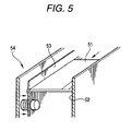
- the recording angle of the magnetic data is defined in the ISO standard of the magnetic card. Therefore, under the present circumstances, as shown in Fig. 5 , the magnetic processing apparatus is provided with a card width-justification mechanism 54 which guides a magnetic card 51 toward a reference plane 52 under pressure using a width justification plate 53.
- width-justification mechanism operates after the verification, it cannot be known whether or not it is operating properly and the skew of the magnetic card is within a normal region. Therefore, even when its incompatibility with the ISO standard, write error and read error occur, it cannot be known whether or not these inconveniences are due to the skew of the magnetic card. The subsequent analysis of error cannot be easily made.
- a magnetic card offsetting device which reduces the generation ratio of a equipment failure by driving and controlling a motor which rotates reversibly a rotary board for a prescribed angle, and a motor which drives a card carrying mechanism in a forward and a backward direction, when an abnormal state, such as skew in a magnetic card, is detected.
- a CPU when a state, such as a skew of a magnetic card is detected at a detection means where four sensors are provided, a CPU is operated based on the abnormality detection output of the detection means and the CPU drives and controls a first motor which turns reversibly a rotary board for 90°, and a second motor which operates oppositely installed rollers in a forward and a backward direction. In this way a corrective control for a magnetic card corresponding to a first error state, a second error state and a third error state can be performed.
- EP-A-0 280 147 discloses a paper sheet handling apparatus in which the thickness of a paper sheet is detected by two thickness detectors arranged side by side in the width direction of a paper sheet conveyance path. Parameters such as paper sheet thickness, length, the existence of a skew and, if skew exists, the skew angle are calculated based on the output signals from the thickness detectors.
- a carrying mechanism for a recording medium which can detect the carrying process of a recording medium and surely eject an optical card even when one side thereof is damaged. Therefore, a card detecting sensor is disposed on both sides of a carrying path in the inner side of the inserting port of a placing plate. When a motor is driven and an optical card is sent by rollers, the introducing state of the optical card is detected by a card detecting sensor.
- a skew detecting apparatus comprises the features of claim 1.
- a medium processing apparatus for processing recording information of a recording medium guided on a medium transfer path, comprises the features of claim 2.
- a magnetic card processing apparatus provided with a magnetic head for data-processing a magnetic card guided to a card transfer path, comprises the features of claim 3.
- the spherical roller is arranged according to claim 4.
- the skew detecting means includes means for alerting a host system to occurrence of an error when it detects that the skew exceeds a limit of the skew displacement.
- a spherical roller in contact with the surface of the medium to be transferred on a medium transfer path is rolled and the skew detecting means acquires a skew displacement of the medium which is transferred on the basis of a degree of rolling of the spherical roller detected in both medium transfer and medium transfer-width direction.
- the skew of the medium can be detected accurately. Therefore, it can be surely known whether or not abnormality occurs in the medium on the basis of the skew detected data.
- the spherical roller rolls are kept in contact with the surface of the magnetic card transferred on the card transfer path.
- the rolling degree of the rolling spherical roller in both medium transfer direction and medium transfer-width direction is detected by the rolling degree detecting means, and the skew detecting means can acquire the skew displacement of the recording medium on the basis of the detected rolling degree.
- the processing state of magnetic data can be detected precisely at that position.
- the magnetic card processing apparatus operates after the verification, whether or not the skew when the card is transferred is proper can be detected accurately. Therefore, it is possible to determine whether or not the card width justifying mechanism operates properly. If occurrence of the magnetic error is prevented, reliability of the magnetic card processing apparatus is improved. Further, by constructing a card processing system which alerts a host system to the contents of the error when it has occurred, the maintenance/management of the magnetic card processing apparatus can be easily carried out.
- the magnetic card processing apparatus 11 includes a card transfer path 13 for transferring a magnetic card 12, and a magnetic head 14 arranged on the card transfer path 13 and a skew detecting device 15 which are arranged on the card transfer path 13.
- the magnetic card 12 is transferred in a horizontal direction while its both ends are guided by the one reference guide plate 16 and the other width-justification guide plate 17 which are parallely arranged on both sides of a card transfer direction apart from each other by the width of the card to be transferred.
- the width-justification guide plate 17 entirely width-justifies the magnetic card 12 from the side of the width-justification guide plate 17 toward the reference guide plate 16 with the aid of the pressing function of pressing stress of pressing springs 18a, ... so that the magnetic card 12 is transferred linearly along the reference guide plate 16.
- a magnetic head 14 is arranged on the card transfer path 13.
- the magnetic head 14 carries out the read/write processing for the magnetic information recoded on the magnetic card 12 while it is kept in slidable contact with the magnetic stripe 12a on the upper face of the card transferred onto the card transfer path 13.
- a skew detecting device 15 is arranged at a position in a card transfer-width direction corresponding to the position of the magnetic head 14.
- the skew detecting device 15, as shown in Fig. 2 includes a transfer direction rolling degree detector 19 and a transfer-width direction rolling degree detector 20.
- the transfer direction rolling degree detector 19 includes a spherical roller 21 which rolls under a certain pressure in contact with the surface of the magnetic card 12 which is transferred on the card transfer path 13 and a front rolling shaft 19a arranged at the center position on the front side of the spherical roller 21.
- the front rolling shaft rolls together with the spherical roller 21.
- the degree of rolling of the front rolling shaft 19a is acquired by a first rotary encoder 19b to compute the degree of transfer of the magnetic card 12.
- the transfer width-direction detector 20 includes a side rolling shaft 20a arranged at the center of the one side of the spherical roller 21.
- the side rolling shaft 20a rolls together with the spherical roller 2.
- the degree of rolling of the side rolling shaft 20a is acquired by a second rotary encoder 20b to compute the transfer degree of the magnetic card 12 in the transfer-width direction.
- a CPU described later acquires the skew of the magnetic card 12 on the basis of the shift of the card in both transfer direction and transfer-width direction. According to the degree of skew, whether or not the processing state of the magnetic data is normal or abnormal is detected precisely.
- Fig. 3 is a block diagram of a control circuit of the magnetic card processing apparatus 11.
- the CPU 31 controls each of the circuit devices along the program stored in a ROM 32 to store readably the control data in an RAM.
- a card detecting sensor S is arranged along the card transfer path 13, and detects the transfer state of the card 12 guided to the transfer path 13.
- a transfer motor M drives the transfer roller (not shown) arranged on the card transfer path in both forward and reverse directions, and forward/reverse- transfers the guided magnetic card 12 in inserting and returning directions.
- a communication device 34 is set so that the data processing contents when an error occurs in the other item than the transaction contents are notified to a host system such a personal computer arranged as a management apparatus for a card processing system.
- a host system such as a personal computer arranged as a management apparatus for a card processing system.
- the data of the magnetic card processing system 11 is managed all the time so that maintenance/management can be made easier. For example, if the skew of the magnetic card acquired by the skew detecting device 15 is displayed on the screen of the host system 35, the performance of the magnetic card processing apparatus can be easily known, and maintenance/inspection such as adjustment and checking can be easily performed.
- the CPU 31 can precisely compute the slight skew formed under the adverse affect of chattering vibration while the magnetic card is transferred, on the basis of the rolling degree detecting data from both transfer direction rolling degree detector 19 and transfer-width direction rolling degree detector 20. Therefore, on the basis of the skew detected data, it can be accurately known whether or not the magnetic card 12 produces abnormal magnetic processing.
- the skew detecting device 15 is arranged at a position in a card transfer-width direction corresponding to the position of the magnetic head 14, the skew of the magnetic card 12 can be acquired at the magnetic processing position to detect the processing state of the magnetic data.
- the skew detecting device 15 when the skew detecting device 15 is arranged at the front stage of the magnetic head 14, the skew degree of the magnetic card 12 can be detected before the magnetic data is processed by the magnetic head 14. Therefore, if the skew unsuitable for the magnetic processing by the magnetic head 14 has occurred, it can be immediately returned for reattempt. Thus, occurrence of the magnetic error for the magnetic card 12 can be prevented.
- the transfer motor M is driven to take in the magnetic card 12 and transfer it (Steps n1 - n2).
- the taken-in magnetic card 12 is guided to the position of the magnetic head 14 along the card transfer path 13.
- the magnetic data of the magnetic card 12 is read (Step n3).
- Step n4 - n5 the number of times of error is counted. If the count value exceeds a prescribed value, it is determined that the error has occurred. In this case, since the processing of the magnetic data is not suitable, this fact is notified to the host system 34. The transaction is rejected to return the magnetic card 12 to a customer (Step n6 - n8).
- the CPU 31 verifies the skew generated state of the magnetic card 12. If the skew has not been generated, it is determined that the error is attributable to the other cause than the skew. This fact is notified to the host system 34 (Step n9). The magnetic card 12 which has been determined "error" and hence is unsuitable for transaction is returned to the customer (Step n10).
- Step n11 the magnetic card 12 having completed the proper transaction is returned to the customer. Thus, one transaction is completed (Step n12).
- the spherical roller rolls being kept, under constant pressure, in contact with the surface of the magnetic card transferred on the card transfer path, the rolling degree of the rolling spherical roller in both card transfer direction and card transfer-width direction is detected by the skew detecting device, and the CPU can acquire the skew of the magnetic card on the basis of the detected rolling degree. Therefore, when the skewed transfer which is not suitable to the processing of the magnetic data is executed, the magnetic processing for the magnetic card is attempted again. Thus, the normal processing of the magnetic data can be assured.
- the processing state of magnetic data can be detected precisely at that position. Further, if the skew detecting device is arranged in front of the magnetic head, occurrence of the magnetic error of the magnetic card owing to unsuitable transfer can be prevented prior to the processing of the magnetic data.
- the magnetic card processing apparatus is manufactured, it is not necessary to test the magnetic card having been actually subjected to the magnetic processing for write to verify the performance of the card justifying mechanism. Further, also when the magnetic card processing apparatus operates, whether or not the skew is proper can be detected accurately. Therefore, it is possible to determine whether or not the card width justifying mechanism which may generate the skew operates properly. In this way, the skewing state when the magnetic data are processed can be checked accurately, the data processing capability for the magnetic card is improved and reliability of the magnetic card processing apparatus is improved. By alerting the host system to the contents of the error when it has occurred, the maintenance/management of the magnetic card processing apparatus can be carried out more easily.
- the skew detecting apparatus corresponds to the skew detecting apparatus 15 in the embodiment.
- the medium processing apparatus corresponds to the magnetic card processing apparatus corresponds to the magnetic card processing apparatus 11;
- the medium transfer path corresponds to the card transfer path 13;
- the medium and recording medium correspond to the magnetic card 12;
- the skew detecting device and rolling degree detecting device correspond to the transfer direction rolling degree detector 19 and transfer-width direction rolling degree detector 20 which are included in the skew detecting apparatus 15 and their control system, i.e. CPU 31.
- the present invention can be realized in various applications falling within the scope of the appended in the claims, and should not be limited to only the configuration of the embodiment described above.
Landscapes
- Engineering & Computer Science (AREA)
- Physics & Mathematics (AREA)
- General Physics & Mathematics (AREA)
- Theoretical Computer Science (AREA)
- Artificial Intelligence (AREA)
- Computer Vision & Pattern Recognition (AREA)
- Controlling Sheets Or Webs (AREA)
- Control Of Vending Devices And Auxiliary Devices For Vending Devices (AREA)
- Conveying Record Carriers (AREA)
- Digital Magnetic Recording (AREA)
Claims (8)
- Schräglauffeststellungsvorrichtung, gekennzeichnet durch:eine sphärische Rolle (21), welche in Berührung mit der Oberfläche eines Mediums rollt, das auf einem Medium (12)-Transferweg (13) geführt wird; undSchräglaufnachweismittel (15) zur Gewinnung einer Schrägversetzung des Mediums (12), welches transferiert wird, auf der Grundlage eines Rollausmaßes der sphärischen Rolle, das sowohl in der Richtung des Mediumtransfers als auch quer zum Mediumtransfer der Rolle (21) festgestellt wird.
- Mediumverarbeitungsvorrichtung zur Verarbeitung von Aufzeichnungsinformation auf einem Aufzeichnungsmedium, welches zu einem Mediumtransferweg geführt wird, gekennzeichnet durch
eine Schräglauffeststellungsvorrichtung nach Anspruch 1, wobei die Schräglauffeststellungsmittel (15) aufweisen:Rollausmaßfeststellungsmittel (19, 20) zur Feststellung des Rollausmaßes der sphärischen Rolle (21) sowohl in Richtung des Mediumtransfers als auch quer zum Mediumtransfer; wobei
die Schräglauffeststellungsmittel so eingerichtet sind, dass sie eine Schrägversetzung des Mediums, welches transferiert wird, auf der Grundlage des mit den Rollausmaßfeststellungsmitteln festgestellten Rollausmaßes gewinnen. - Magnetkartenverarbeitungsvorrichtung, welche aufweist:einen Magnetkopf (14) zur datenbezüglichen Verarbeitung einer Magnetkarte (12), welche zu einem Kartentransferweg (13) geführt wird; gekennzeichnet durcheine Schräglauffeststellungsvorrichtung nach Anspruch 1, wobei die Schräglauffeststellungsmittel (15) aufweisen:Rollausmaßfeststellungsmittel (19, 20) zur Feststellung des Ausmaßes des Rollens der sphärischen Rolle (21) sowohl in Richtung des Mediumtransfers als auch quer zum Mediumtransfer; wobei
die Schräglauffeststellungsmittel so eingerichtet sind, dass sie eine Schrägversetzung des Mediums, welches transferiert wird, auf der Grundlage des mit den Rollausmaßfeststellungsmitteln festgestellten Rollausmaßes gewinnen. - Magnetkartenverarbeitungsvorrichtung nach Anspruch 3, wobei die sphärische Rolle (21) an einer Position angeordnet ist, die in der Mediumtransferrichtung der Position des auf dem Kartentransferweg (13) angeordneten Magnetkopfs (14) entspricht, aber aus der Magnetkopfposition in einer Richtung quer zur Mediumtransferrichtung versetzt ist.
- Schräglauffeststellungsvorrichtung nach Anspruch 1, wobei die Schräglauffeststellungsmittel (15) Mittel enthalten, die ein Hostsystem (35) auf das Auftreten eines Fehlers aufmerksam machen, wenn sie feststellen, dass das Schräglaufausmaß einen Grenzwert der Schrägversetzung überschreitet.
- Mediumverarbeitungsvorrichtung nach Anspruch 2, wobei die Schräglauffeststellungsmittel (15) Mittel enthalten, die ein Hostsystem (35) auf das Auftreten eines Fehlers aufmerksam machen, wenn sie feststellen, dass das Schräglaufausmaß einen Grenzwert der Schrägversetzung überschreitet.
- Magnetkartenverarbeitungsvorrichtung nach Anspruch 3, wobei die Schräglauffeststellungsmittel (15) Mittel enthalten, die ein Hostsystem (35) auf das Auftreten eines Fehlers aufmerksam machen, wenn sie feststellen, dass das Schräglaufausmaß einen Grenzwert der Schrägversetzung überschreitet.
- Kartenverarbeitungssystem, welches das Magnetkartenverarbeitungssystem nach Anspruch 3 und ein Hostsystem (35) zur Verarbeitung von Magnetdaten der Magnetkarte (12) aufweist.
Applications Claiming Priority (2)
| Application Number | Priority Date | Filing Date | Title |
|---|---|---|---|
| JP11115014A JP2000302289A (ja) | 1999-04-22 | 1999-04-22 | 傾き検知装置、媒体処理装置、磁気カード処理装置及びカード処理システム |
| JP11501499 | 1999-04-22 |
Publications (3)
| Publication Number | Publication Date |
|---|---|
| EP1047010A2 EP1047010A2 (de) | 2000-10-25 |
| EP1047010A3 EP1047010A3 (de) | 2004-04-14 |
| EP1047010B1 true EP1047010B1 (de) | 2008-11-05 |
Family
ID=14652134
Family Applications (1)
| Application Number | Title | Priority Date | Filing Date |
|---|---|---|---|
| EP00108683A Expired - Lifetime EP1047010B1 (de) | 1999-04-22 | 2000-04-20 | Winkeldetektor, Verarbeitungsgerät für ein Medium, Verarbeitungsgerät für eine Magnetkarte und Verarbeitungssystem für eine Karte |
Country Status (4)
| Country | Link |
|---|---|
| US (1) | US6467689B1 (de) |
| EP (1) | EP1047010B1 (de) |
| JP (1) | JP2000302289A (de) |
| DE (1) | DE60040707D1 (de) |
Families Citing this family (3)
| Publication number | Priority date | Publication date | Assignee | Title |
|---|---|---|---|---|
| US7870444B2 (en) * | 2005-10-13 | 2011-01-11 | Avago Technologies Fiber Ip (Singapore) Pte. Ltd. | System and method for measuring and correcting data lane skews |
| DE102015115194A1 (de) * | 2015-09-09 | 2017-03-09 | Wincor Nixdorf International Gmbh | Kartenleseeinrichtung und ein damit ausgestattetes Selbstbedienungsterminal sowie Verfahren zur Überwachung desselben |
| EP4007732A4 (de) * | 2019-10-25 | 2023-04-26 | Hewlett-Packard Development Company, L.P. | Schrägstellungserkennung |
Citations (1)
| Publication number | Priority date | Publication date | Assignee | Title |
|---|---|---|---|---|
| US4623787A (en) * | 1983-12-05 | 1986-11-18 | Wico Corporation | Ball and transducer mounting arrangement for mouse |
Family Cites Families (11)
| Publication number | Priority date | Publication date | Assignee | Title |
|---|---|---|---|---|
| JPS62159371A (ja) * | 1986-01-08 | 1987-07-15 | Omron Tateisi Electronics Co | 磁気カ−ドの片寄せ装置 |
| JPH0734218B2 (ja) * | 1987-02-25 | 1995-04-12 | オムロン株式会社 | 紙葉類の放出装置 |
| US5280903A (en) * | 1992-09-02 | 1994-01-25 | Roll Systems, Inc. | Sheet justifier |
| JPH06274703A (ja) * | 1993-01-25 | 1994-09-30 | Omron Corp | カード処理装置 |
| JP3351627B2 (ja) * | 1993-09-16 | 2002-12-03 | 株式会社東芝 | 磁気媒体処理装置 |
| US5681036A (en) * | 1994-10-07 | 1997-10-28 | Canon Kabushiki Kaisha | Sheet feeding device with control of skew-correction |
| US5965862A (en) * | 1994-10-18 | 1999-10-12 | Seiko Epson Corporation | Information detection apparatus and method for printing on a medium and for reading information recorded on the medium |
| JPH08195009A (ja) * | 1995-01-19 | 1996-07-30 | Canon Inc | カード状記録媒体の搬送機構 |
| US6059284A (en) * | 1997-01-21 | 2000-05-09 | Xerox Corporation | Process, lateral and skew sheet positioning apparatus and method |
| JPH10334307A (ja) * | 1997-05-30 | 1998-12-18 | Sanden Corp | 紙幣受入れ装置 |
| GB9717938D0 (en) * | 1997-08-22 | 1997-10-29 | De La Rue Thomas & Co Ltd | Document alignment system |
-
1999
- 1999-04-22 JP JP11115014A patent/JP2000302289A/ja active Pending
-
2000
- 2000-04-20 EP EP00108683A patent/EP1047010B1/de not_active Expired - Lifetime
- 2000-04-20 DE DE60040707T patent/DE60040707D1/de not_active Expired - Lifetime
- 2000-04-21 US US09/556,624 patent/US6467689B1/en not_active Expired - Fee Related
Patent Citations (1)
| Publication number | Priority date | Publication date | Assignee | Title |
|---|---|---|---|---|
| US4623787A (en) * | 1983-12-05 | 1986-11-18 | Wico Corporation | Ball and transducer mounting arrangement for mouse |
Also Published As
| Publication number | Publication date |
|---|---|
| JP2000302289A (ja) | 2000-10-31 |
| DE60040707D1 (de) | 2008-12-18 |
| EP1047010A3 (de) | 2004-04-14 |
| EP1047010A2 (de) | 2000-10-25 |
| US6467689B1 (en) | 2002-10-22 |
Similar Documents
| Publication | Publication Date | Title |
|---|---|---|
| JP4419527B2 (ja) | 小切手処理装置用ホストコンピュータ、小切手処理システム及び小切手処理方法 | |
| US5174562A (en) | Paper sheet handling apparatus | |
| US20200126368A1 (en) | Card reader and control method of card reader | |
| US7568695B2 (en) | Sheet feeder and jam detecting method | |
| EP1047010B1 (de) | Winkeldetektor, Verarbeitungsgerät für ein Medium, Verarbeitungsgerät für eine Magnetkarte und Verarbeitungssystem für eine Karte | |
| US20190163938A1 (en) | Control method of card reader and card reader | |
| US6862081B2 (en) | Sheet transporting apparatus | |
| JP2013001530A (ja) | 紙厚検出装置及び紙厚検出方法 | |
| JPH0135745B2 (de) | ||
| JPH05147768A (ja) | 紙葉類厚さ検出機構 | |
| KR20200144387A (ko) | 매체의 스큐 검출 장치 및 방법 | |
| US6681036B1 (en) | Paper money identification method and device | |
| JP2575748B2 (ja) | 紙葉類の異常検知装置 | |
| KR20110001263A (ko) | Rfid 태그 검사장치 및 방법 | |
| JP2882166B2 (ja) | 読取装置 | |
| JP3683413B2 (ja) | 媒体搬送判定方法および媒体搬送装置 | |
| JP3538386B2 (ja) | 発券機のエラー監視方法 | |
| US20250371294A1 (en) | Card reader | |
| JP2001116505A (ja) | 媒体厚検出装置 | |
| JP2000285278A (ja) | 紙葉類の斜行検知方法、紙葉類の斜行検知装置、および紙葉類計数機 | |
| JP5717185B2 (ja) | カードリーダ/ライタ、カード位置情報生成方法およびカード位置情報生成プログラム | |
| JP2018173889A (ja) | カード状媒体処理装置 | |
| JP6854709B2 (ja) | 磁気センサ検出ユニット、カード処理装置、および磁気センサ検出方法 | |
| JP2004098499A (ja) | 発券プリンタ | |
| JPS5914786B2 (ja) | 自動取引装置 |
Legal Events
| Date | Code | Title | Description |
|---|---|---|---|
| PUAI | Public reference made under article 153(3) epc to a published international application that has entered the european phase |
Free format text: ORIGINAL CODE: 0009012 |
|
| 17P | Request for examination filed |
Effective date: 20000517 |
|
| AK | Designated contracting states |
Kind code of ref document: A2 Designated state(s): AT BE CH CY DE DK ES FI FR GB GR IE IT LI LU MC NL PT SE |
|
| AX | Request for extension of the european patent |
Free format text: AL;LT;LV;MK;RO;SI |
|
| PUAL | Search report despatched |
Free format text: ORIGINAL CODE: 0009013 |
|
| RIC1 | Information provided on ipc code assigned before grant |
Ipc: 7G 06K 13/067 B Ipc: 7G 11B 17/00 B Ipc: 7G 06K 7/00 A Ipc: 7G 06K 7/08 B |
|
| AK | Designated contracting states |
Kind code of ref document: A3 Designated state(s): AT BE CH CY DE DK ES FI FR GB GR IE IT LI LU MC NL PT SE |
|
| AX | Request for extension of the european patent |
Extension state: AL LT LV MK RO SI |
|
| AKX | Designation fees paid |
Designated state(s): DE FR GB IT |
|
| RAP1 | Party data changed (applicant data changed or rights of an application transferred) |
Owner name: HITACHI-OMRON TERMINAL SOLUTIONS, CORP. |
|
| 17Q | First examination report despatched |
Effective date: 20071102 |
|
| GRAP | Despatch of communication of intention to grant a patent |
Free format text: ORIGINAL CODE: EPIDOSNIGR1 |
|
| GRAS | Grant fee paid |
Free format text: ORIGINAL CODE: EPIDOSNIGR3 |
|
| GRAA | (expected) grant |
Free format text: ORIGINAL CODE: 0009210 |
|
| AK | Designated contracting states |
Kind code of ref document: B1 Designated state(s): DE FR GB IT |
|
| REG | Reference to a national code |
Ref country code: GB Ref legal event code: FG4D |
|
| REF | Corresponds to: |
Ref document number: 60040707 Country of ref document: DE Date of ref document: 20081218 Kind code of ref document: P |
|
| PLBE | No opposition filed within time limit |
Free format text: ORIGINAL CODE: 0009261 |
|
| STAA | Information on the status of an ep patent application or granted ep patent |
Free format text: STATUS: NO OPPOSITION FILED WITHIN TIME LIMIT |
|
| 26N | No opposition filed |
Effective date: 20090806 |
|
| PG25 | Lapsed in a contracting state [announced via postgrant information from national office to epo] |
Ref country code: IT Free format text: LAPSE BECAUSE OF FAILURE TO SUBMIT A TRANSLATION OF THE DESCRIPTION OR TO PAY THE FEE WITHIN THE PRESCRIBED TIME-LIMIT Effective date: 20081105 |
|
| REG | Reference to a national code |
Ref country code: DE Ref legal event code: R082 Ref document number: 60040707 Country of ref document: DE Representative=s name: KILIAN KILIAN & PARTNER, DE |
|
| REG | Reference to a national code |
Ref country code: FR Ref legal event code: PLFP Year of fee payment: 16 |
|
| PGFP | Annual fee paid to national office [announced via postgrant information from national office to epo] |
Ref country code: GB Payment date: 20150415 Year of fee payment: 16 Ref country code: DE Payment date: 20150414 Year of fee payment: 16 |
|
| PGFP | Annual fee paid to national office [announced via postgrant information from national office to epo] |
Ref country code: FR Payment date: 20150408 Year of fee payment: 16 |
|
| REG | Reference to a national code |
Ref country code: DE Ref legal event code: R119 Ref document number: 60040707 Country of ref document: DE |
|
| GBPC | Gb: european patent ceased through non-payment of renewal fee |
Effective date: 20160420 |
|
| REG | Reference to a national code |
Ref country code: FR Ref legal event code: ST Effective date: 20161230 |
|
| PG25 | Lapsed in a contracting state [announced via postgrant information from national office to epo] |
Ref country code: FR Free format text: LAPSE BECAUSE OF NON-PAYMENT OF DUE FEES Effective date: 20160502 Ref country code: DE Free format text: LAPSE BECAUSE OF NON-PAYMENT OF DUE FEES Effective date: 20161101 Ref country code: GB Free format text: LAPSE BECAUSE OF NON-PAYMENT OF DUE FEES Effective date: 20160420 |