EP1043805B1 - Elektrische Verbindungs- oder Anschlussklemme - Google Patents
Elektrische Verbindungs- oder Anschlussklemme Download PDFInfo
- Publication number
- EP1043805B1 EP1043805B1 EP00104111A EP00104111A EP1043805B1 EP 1043805 B1 EP1043805 B1 EP 1043805B1 EP 00104111 A EP00104111 A EP 00104111A EP 00104111 A EP00104111 A EP 00104111A EP 1043805 B1 EP1043805 B1 EP 1043805B1
- Authority
- EP
- European Patent Office
- Prior art keywords
- temperature
- clamp
- housing
- sensitive element
- heat
- Prior art date
- Legal status (The legal status is an assumption and is not a legal conclusion. Google has not performed a legal analysis and makes no representation as to the accuracy of the status listed.)
- Expired - Lifetime
Links
- 239000004020 conductor Substances 0.000 claims abstract 3
- 238000004804 winding Methods 0.000 claims description 15
- 239000012777 electrically insulating material Substances 0.000 claims description 3
- 238000012546 transfer Methods 0.000 abstract description 7
- 238000003780 insertion Methods 0.000 abstract description 6
- 230000037431 insertion Effects 0.000 abstract description 6
- 239000011810 insulating material Substances 0.000 description 6
- 238000004519 manufacturing process Methods 0.000 description 5
- 239000000463 material Substances 0.000 description 5
- 230000001419 dependent effect Effects 0.000 description 4
- 238000012544 monitoring process Methods 0.000 description 4
- 238000000465 moulding Methods 0.000 description 3
- 230000006978 adaptation Effects 0.000 description 2
- 238000005470 impregnation Methods 0.000 description 2
- 239000002184 metal Substances 0.000 description 2
- 230000005855 radiation Effects 0.000 description 2
- 229910001369 Brass Inorganic materials 0.000 description 1
- 229910000906 Bronze Inorganic materials 0.000 description 1
- 239000010951 brass Substances 0.000 description 1
- 239000010974 bronze Substances 0.000 description 1
- 238000010276 construction Methods 0.000 description 1
- KUNSUQLRTQLHQQ-UHFFFAOYSA-N copper tin Chemical compound [Cu].[Sn] KUNSUQLRTQLHQQ-UHFFFAOYSA-N 0.000 description 1
- 230000006735 deficit Effects 0.000 description 1
- 238000006073 displacement reaction Methods 0.000 description 1
- 230000007613 environmental effect Effects 0.000 description 1
- 238000011156 evaluation Methods 0.000 description 1
- 238000010438 heat treatment Methods 0.000 description 1
- 230000001771 impaired effect Effects 0.000 description 1
- 238000009413 insulation Methods 0.000 description 1
- WABPQHHGFIMREM-UHFFFAOYSA-N lead(0) Chemical compound [Pb] WABPQHHGFIMREM-UHFFFAOYSA-N 0.000 description 1
- 238000013507 mapping Methods 0.000 description 1
- 238000000034 method Methods 0.000 description 1
- 230000001681 protective effect Effects 0.000 description 1
- 238000002791 soaking Methods 0.000 description 1
- 239000007858 starting material Substances 0.000 description 1
- 238000012549 training Methods 0.000 description 1
Images

Classifications
-
- H—ELECTRICITY
- H01—ELECTRIC ELEMENTS
- H01F—MAGNETS; INDUCTANCES; TRANSFORMERS; SELECTION OF MATERIALS FOR THEIR MAGNETIC PROPERTIES
- H01F27/00—Details of transformers or inductances, in general
- H01F27/40—Structural association with built-in electric component, e.g. fuse
- H01F27/402—Association of measuring or protective means
-
- H—ELECTRICITY
- H01—ELECTRIC ELEMENTS
- H01R—ELECTRICALLY-CONDUCTIVE CONNECTIONS; STRUCTURAL ASSOCIATIONS OF A PLURALITY OF MUTUALLY-INSULATED ELECTRICAL CONNECTING ELEMENTS; COUPLING DEVICES; CURRENT COLLECTORS
- H01R9/00—Structural associations of a plurality of mutually-insulated electrical connecting elements, e.g. terminal strips or terminal blocks; Terminals or binding posts mounted upon a base or in a case; Bases therefor
- H01R9/22—Bases, e.g. strip, block, panel
- H01R9/24—Terminal blocks
- H01R9/2425—Structural association with built-in components
-
- H—ELECTRICITY
- H01—ELECTRIC ELEMENTS
- H01F—MAGNETS; INDUCTANCES; TRANSFORMERS; SELECTION OF MATERIALS FOR THEIR MAGNETIC PROPERTIES
- H01F27/00—Details of transformers or inductances, in general
- H01F27/40—Structural association with built-in electric component, e.g. fuse
- H01F27/402—Association of measuring or protective means
- H01F2027/406—Temperature sensor or protection
Definitions
- the invention relates to an electrical connection or Terminal with one of electrically insulating Material existing housing and with arranged in the housing electrically conductive connection or Connection means which line insertion openings in the Housing and clamping means for introduced into it electrical Lines are assigned.
- connection or terminals are known in practice in various embodiments.
- Your electrically conductive connection or connection means are often essentially pod, tube, Laschen- or rail-shaped metal parts Brass or bronze while as clamping means clamping screws, Clamping springs, insulation displacement contacts and the like are provided.
- the connection or connection means are safely stored in the insulating housing, the housing itself being fasteners in Shape of screw holes, cutouts for sliding on fastening straps, etc. may have.
- terminals are also typically used for Electrical equipment used, in which they usually are directly attached.
- the terminals themselves can be formed one or more poles, and also several terminals combined to form so-called terminal strips could be.
- terminal strips Under the term “clamp” are in Within the scope of the present invention also such terminal strips and corresponding terminal arrangement understood.
- ballasts for gas discharge lamps, Transformers, chokes and the like must depending on their use with a thermal fuse or monitoring to ensure that when a predetermined excess temperature is exceeded the device is switched off. The same applies also for lights, where for safety reasons a predetermined excess temperature should not be exceeded may.
- the temperature sensitive Element is doing in a space between the actual the clamping inserts for the lines receiving Body and the winding head in larger Distance from the support surface of the clamp arranged.
- a receiving space of the main body can Kal tleitersay a cal be arranged, which is above the support surface adjacent clamping inserts is located.
- An exchange is against other protective elements not possible, because this a differently sized recording room require.
- the thermal fuse in a particularly large distance above the support surface.
- connection or Terminal based on the original consideration, the connection or Use terminal itself as a temperature sensor, i.e. the temperature monitoring in the connection or Lay the connection terminal.
- the required Limit temperature monitoring is completed by that at the Device attached, new connection or Terminal causes and is independent of any Impregnation or hardening processes during the manufacture of the device.
- the invention also allows optimal adaptation of the Temperature response of the in the connection or terminal accommodated, heat-sensitive element to the thermal conditions and properties of the assigned device or the material used for this. By appropriate choice of connection or Connection terminal can also only in the final assembly be decided whether a device according to the respective Requirements with or without thermal protection device is delivered.
- the invention is not limited to the application for ballasts and transformers of different power, Types and uses limited. It can be everywhere applied where it matters, one Limit temperature monitoring.
- the selection of the each in the new connection or terminal used temperature-sensitive element depends on the conditions of use and the purpose.
- temperature-sensitive Elements can be heat protection switches, PCT resistors, thermal fuse elements and the like be, just to name a few examples. It are generally speaking, electrical switching elements that temperature dependent their electrical state value between change their electrical connections. These include also non-contact temperature sensors, the optionally in signal evaluation circuits, etc. included are.
- the at least one temperature-sensitive element can be embedded in the material of the terminal housing, For example, be poured, but it is usually appropriate if the housing means for receiving the having used temperature-sensitive element, in turn, for example, at least one bag, channel or groove-like depression or recess have, in which the temperature-sensitive element is used. Electrical Connections of the temperature-sensitive element are with Advantage with the connection or connection means of Clamp connected, so with the insertion and the contacting the line feeds the temperature sensitive Element automatically switched in an appropriate manner is.
- the temperature-sensitive element can at a Side of the housing of the terminal at least partially exposed can be arranged, but the arrangement can also be made such that the temperature-sensitive Element near the bearing surface of the Terminal housing arranged and at least partially Covered by a heat-permeable wall to the outside is.
- the heat-permeable wall can be made of an electrical insulating material of low wall thickness exist and integrally formed on the housing or by a cover part connected to the housing be formed. To a particularly good heat conduction too cases are also conceivable in which the heat-permeable Wall made of metal.
- the location of the temperature-sensitive element in the terminal housing depends on the structure and mounting position of the terminal their intended use.
- the temperature sensitive Element in heat transferring assignment to a support surface and / or to a cable entry openings containing side surface of the housing be arranged.
- the heat-sensitive element in im substantially axial alignment with connecting or connecting means is arranged.
- heat transfer mapping to an outer surface of the housing is understood that the heat transfer from this outer surface on the heat-sensitive Element as unobstructed as possible, but at least defined is possible.
- the heat transfer itself can be dependent on the type of heat-sensitive used Element and the application of the connection or connection terminal by heat conduction, heat radiation (infrared radiation) u. Like. happen.
- the invention is also the use of in the above-described connection according to the invention or terminal as temperature monitor or temperature fuse for a device to be thermally monitored, For example, a lamp, a built on a board Circuit, a ballast for gas discharge devices, a choke, a transformer and the like. These include non-electrical devices in which It only matters that they have a certain limit temperature do not exceed.
- the new connection or terminal as a temperature sensor.
- the invention is finally also a electrical device, in particular a ballast or Transformer or the like, with an inventive Terminal in which the arranged in the terminal housing temperature-sensitive element through the with the device connected terminal in heat transfer assignment to a heat-emitting, monitored area of the device is held.
- the area to be monitored may e.g. at a current-carrying winding or one with this formed in thermally conductive connection standing part be.
- the device can also be a light.
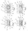
- the schematically illustrated in Figs. 1 to 4 three-pin connection or connection terminal 1 is as erklemme formed and has one of an electrical housing made of insulating plastic material 2 on.
- the housing 2 consists of three identically designed elongated housing parts or units 3, the by integrally formed webs 4, 5 are interconnected, in whose area is one from top to bottom, one Fastening device forming screw hole 6 is arranged is (Fig. 5).
- Each of the rectangular in cross-section Housing units 3 has one of the front 7 to Back 8 through, channel-like recess 9, in the one forming a connecting or connecting means, metallic clamping sleeve 10 is inserted.
- Each of the clamping sleeves 10 is not in a conventional manner with two further provided threaded holes provided in the Clamping screws 11 are screwed.
- the clamping sleeves 10 and the clamping screws 11 are in the housing units. 3 or in this molded insulating material sleeves 12th safe to touch.
- a temperature-sensitive one Element 15 is inserted, which is a substantially rectangular Has cross-sectional shape and two electrical Connecting wires 16 carries, which bent approximately L-shaped in the manner shown in Fig. 2 manner in the adjacent two clamping sleeves 10 are inserted, one of which Central clamping sleeve 10 of the three-terminal screw 1 is.
- the temperature-sensitive element 15 is symmetrical to the two, the connecting wires 16 associated clamping sleeves 10, 10 a arranged and in the axial direction a housing shoulder 17 ( Figure 1) on the lead wires Fixed 16 opposite end face.
- the heat-sensitive Element 15 On the the footprint 14 facing side is the heat-sensitive Element 15 through a thin, heat-permeable Covered wall 18, which is integrally formed on the two webs 13a is and consists of the material of the terminal housing 2.
- the heat-permeable wall 18 also as be formed separate part, with the terminal housing glued, locked or otherwise connected.
- the temperature-sensitive element 15 in the of the webs 13 a of the heat-permeable Wall 18 and the overlying parts of the terminal housing 2 limited, pocket-shaped recess 19 is inserted and therein by the jammed in the collars 10, 10a Connecting wires 16 is held.
- the temperature-sensitive element 15 also glued or otherwise be anchored as well as possible is, the pocket-like recess 19, at least on one Front side to close by a closure means or to shed.
- the temperature-sensitive element 15 also in the production of the terminal housing 2 directly have been embedded in its material.
- the clamping sleeve 10a receiving channel-like recess 9 of the middle housing part 3 is on the Lead wires 16 of the temperature-sensitive element 15 facing away from the front 7, the line connection side the clamp, by a wall 20 (Fig. 3) closed, so that the lead wire inserted into the ferrule 10a 16 is not accidentally jammed with a power cord can be.
- the heat-sensitive Element 15 over the heat-permeable wall 18 in heat transfer assignment to the footprint 14 of the terminal arranged.
- the temperature sensitive Element 15 may be a thermal circuit breaker PCT resistor, a thermal fuse element or generally a heat sensor element connected to its connecting wires 16 outputs a temperature-dependent signal or the temperature dependent one between the leads 16 occurring electrical state variable, eg. changed a resistance or a switching state.
- the temperature-sensitive element 15 in simply plugged into the terminal housing 2, i. interchangeable be arranged so that the clamp 1 flexible to the Conditions of the respective purpose are adapted can.
- the pad 22 for example, a part of a lamp housing be on which the screw 1 is attached is and the temperature of the temperature sensitive Element 15 is monitored when reaching a limit temperature
- the lamp circuit interrupts.
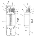
- each of the ballasts 23 has a laminated core 24, that on a marginally with him crimped, metallic Attachment rail 25 is attached.
- the frontal side over the laminated core 24 protruding end windings not further illustrated winding are by Isoliermaterialkappen 26 covered, as in principle, for example.
- Isoliermaterialkappen 26 covered, as in principle, for example.
- Each of the insulating material caps 26 carries molded, one-sided slotted tubes 27, on the connection side of the ballast Connecting sleeves 28 are clamped, which are connected to the winding connection wires are stuck.
- the ferrules 28 are with the clamping sleeves 10, 10 a subsequent to the associated Isoliermaterialkappe 26 on the mounting rail 25 attached screw terminal 1 jammed, as Connection terminal for the ballast is used.
- the screw clamp 1 is on the mounting rail 25 by means of a unlatched, substantially L-shaped flap 29 attached, in one of the below one of the two bridges 4 lying through openings 30 (Fig. 2) of the terminal housing 2 sticks out.
- the arrangement can be made in this way be that the resilient flap 29 directly on the temperature sensitive element 15 presses, so this over the heat-permeable wall 18 against the mounting rail 25 is pressed.
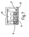
- FIGS. 5 to 7 is the temperature-sensitive member 15 in the reference to FIG. 1 to 4 described manner in heat transfer assignment arranged to the footprint 14, wherein it is laterally offset from the plane of symmetry of the terminal housing 2, in the of four adjacent clamping screws 16 bounded area sits.
- the temperature sensitive Element 15 therefore feels the temperature of the mounting rail 25, in thermally conductive connection with the Laminated core 24 and the lamp housing is. In operation it is, as seen in Fig. 5, in series between the in the two outer glovesssein technological Anlagen réelleen 30, 31 inserted and with the clamping sleeves 10 on the line connection side 7 connected ladders.
- the clamping sleeve 10a of the middle clamping screw pair 11 is only used for connection of the insertion wire 16 inserted in it with the winding connection sleeve 28, as shown by the Fig. 2, 3 has already been explained.
- the temperature-sensitive element 15 in a pocket or channel-shaped recess 36 of the central Housing part 3 upright inserted from below with its shortened clamp sleeve 10b. It feels Therefore - if necessary, a heat-permeable thin wall 18 - the temperature of the mounting rail 25.
- the arrangement is made such that the temperature-sensitive Element 15 on the cable entry openings 30 and 31 associated side 7 of the terminal housing 2 is exposed. This can be the temperature-sensitive Element 15 also act on page 7 as a temperature sensor, what it possibly with not shown additional equipment parts may be in contact.
- the application of the new connection and terminal is, as already mentioned, not on ballasts, Chokes. Transformers and the like with windings limited equipment limited.
- the clamp can also as a temperature sensor for non-electrical devices and equipment be used.
Landscapes
- Engineering & Computer Science (AREA)
- Power Engineering (AREA)
- Connections Arranged To Contact A Plurality Of Conductors (AREA)
- Fuses (AREA)
- Thermistors And Varistors (AREA)
- Coupling Device And Connection With Printed Circuit (AREA)
- Connection Of Batteries Or Terminals (AREA)
- Connections Effected By Soldering, Adhesion, Or Permanent Deformation (AREA)
- Conductive Materials (AREA)
Description
- Fig. 1
- eine Verbindungs- oder Anschlußklemme gemäß der Erfindung, im axialen Schnitt in einer Seitenansicht;
- Fig. 2
- die Klemme nach Fig. 1 in einer Ansicht der Geräte-Anschlußseite;
- Fig. 3
- die Klemme nach Fig. 2 in einer Ansicht der Leitungs-Anschlußseite;
- Fig. 4
- die Klemme nach Fig. 1 unter Veranschaulichung einer Geräte-Befestigungseinrichtung und eines Geräte-Anschlußes;
- Fig. 5
- ein Vorschaltgerät mit einer Anschlußklemme nach Fig. 1 in der Draufsicht;
- Fig. 6
- das Vorschaltgerät nach Fig. 5 in einer Seitenansicht, unter Veranschaulichung der Anschlußklemme im Längsschnitt entsprechend Fig. 4;
- Fig. 7
- das Vorschaltgerät nach Fig. 6 in einer Ansicht der Leitungs-Einführseite;
- Fig. 8
- ein Vorschaltgerät mit einer Anschlußklemme gemäß der Erfindung in einer weiteren abgewandelten Ausführungsform und in einer Draufsicht;
- Fig. 9
- das Vorschaltgerät nach Fig. 8 in einer Seitenansicht unter Veranschaulichung der Anschlußklemme im Längsschnitt und
- Fig. 10
- das Vorschaltgerät nach Fig. 8 in einer Ansicht der Leitungs-Einführseite.
Claims (16)
- Elektrische Verbindungs- oder Anschlussklemme, mit einem aus elektrisch isolierendem Material bestehenden, eine Auflagefläche aufweisenden Gehäuse (2) und mit in dem Gehäuse angeordneten, elektrisch leitenden Verbindungs- oder Anschlussmitteln (10), denen Leitungseinführöffnungen in dem Gehäuse und Klemmmittel (11) für in sie eingeführte elektrische Leitungen zugeordnet sind, wobei das Gehäuse (2) wenigstens ein elektrische Anschlüsse (16) aufweisendes, temperaturempfindliches Element (15) enthält, dadurch gekennzeichnet, dass das temperaturempfindliche Element in wärmeübertragender Zuordnung zu der Auflagefläche des Gehäuses angeordnet ist.
- Klemme nach Anspruch 1, dadurch gekennzeichnet, dass das Gehäuse (2) Einrichtungen (19) zur Aufnahme des eingesetzten temperaturempfindlichen Elementes (15) aufweist.
- Klemme nach Anspruch 2, dadurch gekennzeichnet, dass die Einrichtungen zur Aufnahme des temperaturempfindlichen Elementes zumindest eine taschen-, kanal- oder rinnenartige Vertiefung oder Aussparung (19) aufweisen, in die das temperaturempfindliche Element (15) eingesetzt ist.
- Klemme nach einem der vorhergehenden Ansprüche, dadurch gekennzeichnet, dass elektrische Anschlüsse (16) des temperaturempfindlichen Elementes mit den Verbindungs- oder Anschlussmitteln (10) verbunden sind.
- Klemme nach einem der vorhergehenden Ansprüche, dadurch gekennzeichnet, dass das temperaturempfindliche Element (15) an einer Seite des Gehäuses (2) wenigstens teilweise freiliegend angeordnet ist.
- Klemme nach einem der Ansprüche 1 bis 4, dadurch gekennzeichnet, dass das temperaturempfindliche Element (15) zumindest bereichsweise durch eine wärmedurchlässige Wand (18) nach außen hin abgedeckt ist.
- Klemme nach Anspruch 6, dadurch gekennzeichnet, dass die wärmedurchlässige Wand (18) aus einem dünnen, elektrisch isolierenden Material besteht.
- Klemme nach Anspruch 6 oder 7, dadurch gekennzeichnet, dass die wärmedurchlässige Wand (18) einstückig an dem Gehäuse ausgebildet ist.
- Klemme nach einem der Ansprüche 6 bis 8, dadurch gekennzeichnet, dass die wärmedurchlässige Wand (18) durch ein mit dem Gehäuse verbundenes Abdeckteil gebildet ist.
- Klemme nach einem der Ansprüche 1 bis 9, dadurch gekennzeichnet, dass das temperaturempfindliche Element (15) in wärmeübertragender Zuordnung zu einer Leitungseinführungsöffnungen enthaltenden Seitenfläche des Gehäuses (2) angeordnet ist.
- Klemme nach einem der Ansprüche 3 bis 9, dadurch gekennzeichnet, dass das wärmeempfindliche Element (15) in im Wesentlichen axialer Ausrichtung zu Verbindungs- oder Anschlußmitteln (10) angeordnet ist.
- Verwendung der Verbindungs- oder Anschlußklemme nach einem der Ansprüche 1 bis 11 als Temperaturwächter oder Temperatursicherung für eine thermisch zu überwachende Einrichtung.
- Elektrisches Gerät, insbesondere Vorschaltgerät, Transformator oder dergleichen mit einer Klemme nach einem der Ansprüche 1 bis 11, dadurch gekennzeichnet, dass das in dem Klemmengehäuse (2) angeordnete temperaturempfindliche Element (15) durch die mit dem Gerät verbundene Klemme in wärmeübertragender Zuordnung zu einem wärmeabgebenden, zu überwachenden Bereich des Gerätes gehalten ist.
- Gerät nach Anspruch 13, dadurch gekennzeichnet, dass der zu überwachende Bereich an einer stromdurchflossenen Wicklung oder einem mit dieser in wärmeleitender Verbindung stehenden Teil ausgebildet ist.
- Gerät nach Anspruch 13 oder 14, dadurch gekennzeichnet, dass die Klemme (1) auf eine aus wärmeleitendem Material bestehende Unterlage (26) aufgesetzt ist und das temperaturempfindliche Element (15) durch die Klemme (1) in wärmeübertragender Zuordnung zu dieser Unterlage gehalten ist.
- Gerät nach Anspruch 13 oder 14 , dadurch gekennzeichnet, dass es eine Leuchte (22) ist.
Applications Claiming Priority (2)
| Application Number | Priority Date | Filing Date | Title |
|---|---|---|---|
| DE19915355A DE19915355A1 (de) | 1999-04-06 | 1999-04-06 | Elektrische Verbindungs- oder Anschlußklemme |
| DE19915355 | 1999-04-06 |
Publications (3)
| Publication Number | Publication Date |
|---|---|
| EP1043805A2 EP1043805A2 (de) | 2000-10-11 |
| EP1043805A3 EP1043805A3 (de) | 2001-12-12 |
| EP1043805B1 true EP1043805B1 (de) | 2005-08-24 |
Family
ID=7903576
Family Applications (1)
| Application Number | Title | Priority Date | Filing Date |
|---|---|---|---|
| EP00104111A Expired - Lifetime EP1043805B1 (de) | 1999-04-06 | 2000-02-29 | Elektrische Verbindungs- oder Anschlussklemme |
Country Status (4)
| Country | Link |
|---|---|
| EP (1) | EP1043805B1 (de) |
| AT (1) | ATE303005T1 (de) |
| DE (2) | DE19915355A1 (de) |
| ES (1) | ES2244370T3 (de) |
Families Citing this family (5)
| Publication number | Priority date | Publication date | Assignee | Title |
|---|---|---|---|---|
| DE20201632U1 (de) | 2002-02-01 | 2002-05-23 | Manfred Fladung GmbH, 63776 Mömbris | Steckverbinder |
| DE10258281B4 (de) * | 2002-12-13 | 2007-02-08 | Vossloh-Schwabe Deutschland Gmbh | Anschlusseinrichtung, insbesondere für elektrische Betriebsmittel |
| CN107607215B (zh) * | 2016-07-11 | 2024-07-12 | 泰科电子(上海)有限公司 | 温度测量组件、温度测量装置及电器组件 |
| DE102017121937B4 (de) * | 2017-09-21 | 2024-07-25 | Phoenix Contact Gmbh & Co. Kg | Steckverbinder |
| CN115000733B (zh) * | 2022-08-04 | 2022-10-25 | 珠海市中力电力设备有限公司 | 一体式新型电缆终端转接线夹 |
Family Cites Families (9)
| Publication number | Priority date | Publication date | Assignee | Title |
|---|---|---|---|---|
| NL7611328A (nl) * | 1976-10-14 | 1978-04-18 | Philips Nv | Induktieve stabilisatieballast voor een ont- ladingslamp. |
| DE2916639C2 (de) * | 1979-04-25 | 1983-01-20 | Peter 7530 Pforzheim Hofsäss | Spulenkörper mit einem Wärmeschutzschalter |
| DE3006311A1 (de) * | 1980-02-20 | 1981-08-27 | Fa. Hermann Schwabe, 7067 Urbach | Vorschaltgeraet, z.b. drossel, fuer gasentladungslampen |
| DE3247318A1 (de) * | 1982-12-21 | 1984-06-28 | Ceag Licht- Und Stromversorgungstechnik Gmbh, 4770 Soest | Vorschaltgeraet mit temperatursicherung fuer leuchten mit leuchtstofflampen |
| DE3309110C2 (de) * | 1983-03-15 | 1985-03-21 | Schwabe GmbH & Co KG Elektrotechnische Fabrik, 7067 Urbach | Drossel oder Transformator, insbesondere als Vorschaltgerät für Gasentladungslampen |
| DE3342395A1 (de) * | 1983-11-24 | 1985-06-05 | Adels-Contact Elektrotechnische Fabrik GmbH & Co KG, 5060 Bergisch Gladbach | Anschlussvorrichtung mit einer, eine mehrzahl von buchsenklemmen aus metall und einen klemmenkoerper aus isoliermaterial aufweisenden verbindungsklemme |
| DE8801789U1 (de) * | 1988-02-11 | 1988-03-24 | Zumtobel Ag, Dornbirn | Elektrische Anschlußklemme |
| DE3911758A1 (de) * | 1988-09-06 | 1990-03-15 | Stefan Tupi | Vorschaltgeraet |
| DE29619953U1 (de) * | 1996-11-16 | 1997-01-23 | A. Grothe & Söhne GmbH & Co. KG, 50969 Köln | Kleintransformator |
-
1999
- 1999-04-06 DE DE19915355A patent/DE19915355A1/de not_active Withdrawn
-
2000
- 2000-02-29 DE DE50011004T patent/DE50011004D1/de not_active Expired - Lifetime
- 2000-02-29 ES ES00104111T patent/ES2244370T3/es not_active Expired - Lifetime
- 2000-02-29 EP EP00104111A patent/EP1043805B1/de not_active Expired - Lifetime
- 2000-02-29 AT AT00104111T patent/ATE303005T1/de active
Also Published As
| Publication number | Publication date |
|---|---|
| ES2244370T3 (es) | 2005-12-16 |
| DE19915355A1 (de) | 2000-10-26 |
| EP1043805A3 (de) | 2001-12-12 |
| DE50011004D1 (de) | 2005-09-29 |
| EP1043805A2 (de) | 2000-10-11 |
| ATE303005T1 (de) | 2005-09-15 |
Similar Documents
| Publication | Publication Date | Title |
|---|---|---|
| DE69507848T2 (de) | Kompakte Schutzeinrichtung | |
| DE69323126T2 (de) | Schutzsensor für Elektromotor | |
| EP0088390A1 (de) | Schutzeinrichtung in elektrisch betriebenen Geräten | |
| DE10017816A1 (de) | Heizungsvorrichtung mit elektrischen Heizelementen für Wasserbetten | |
| DE4336564C2 (de) | Temperaturwächter | |
| DE202017106035U1 (de) | Elektrischer Netzstecker | |
| EP1043805B1 (de) | Elektrische Verbindungs- oder Anschlussklemme | |
| DE19950694C2 (de) | Schalter | |
| DE2809471A1 (de) | Fassung mit uebertemperatur-schutzschalter fuer eine gluehlampe mit schraubsockel | |
| DE29906950U1 (de) | Beheizter Schaltschrank und zugehörige Heizvorrichtung | |
| DE10308724C5 (de) | Schmiegsame Wärmevorrichtung | |
| EP1224714A2 (de) | Anschlussklemme | |
| WO2004066676A1 (de) | Schmiegsame wärmevorrichtung | |
| DE10258281B4 (de) | Anschlusseinrichtung, insbesondere für elektrische Betriebsmittel | |
| EP2233353A1 (de) | Zigarettenanzünder, insbesondere für Kraftfahrzeuge | |
| DE102004015394A1 (de) | Schalter mit isolierter Positioniertasche für Heizwiderstand | |
| DE69129468T2 (de) | Elektrischer rohrheizkörper mit einer temperaturkontrolleinrichtung | |
| DE4205699A1 (de) | Vorrichtung zum Schützen eines Geräts | |
| EP0777239B1 (de) | Gehäuseanordnung zur vergossenen Aufnahme eines Transformators | |
| DE2652495B2 (de) | Elektrische Schmelzsicherung | |
| DE1219579B (de) | Thermoschutzschalter | |
| EP0162940A1 (de) | Überlastsicherungsschalter | |
| DE20302568U1 (de) | Elektrisch beheizbare Wärmevorrichtung mit einem schmiegsamen Heizkörper | |
| DE2513494A1 (de) | Temperaturschutzschalter fuer rohrheizkoerper | |
| DE19953954A1 (de) | Anschlußklemme |
Legal Events
| Date | Code | Title | Description |
|---|---|---|---|
| PUAI | Public reference made under article 153(3) epc to a published international application that has entered the european phase |
Free format text: ORIGINAL CODE: 0009012 |
|
| AK | Designated contracting states |
Kind code of ref document: A2 Designated state(s): AT DE ES FI FR IT Kind code of ref document: A2 Designated state(s): AT BE CH CY DE DK ES FI FR GB GR IE IT LI LU MC NL PT SE |
|
| AX | Request for extension of the european patent |
Free format text: AL;LT;LV;MK;RO;SI |
|
| PUAL | Search report despatched |
Free format text: ORIGINAL CODE: 0009013 |
|
| AK | Designated contracting states |
Kind code of ref document: A3 Designated state(s): AT BE CH CY DE DK ES FI FR GB GR IE IT LI LU MC NL PT SE |
|
| AX | Request for extension of the european patent |
Free format text: AL;LT;LV;MK;RO;SI |
|
| RIC1 | Information provided on ipc code assigned before grant |
Free format text: 7H 01R 9/24 A, 7H 01R 13/713 B, 7H 01F 27/40 B |
|
| 17P | Request for examination filed |
Effective date: 20020517 |
|
| AKX | Designation fees paid |
Free format text: AT DE ES FI FR IT |
|
| 17Q | First examination report despatched |
Effective date: 20040810 |
|
| RAP1 | Party data changed (applicant data changed or rights of an application transferred) |
Owner name: VOSSLOH-SCHWABE DEUTSCHLAND GMBH |
|
| GRAP | Despatch of communication of intention to grant a patent |
Free format text: ORIGINAL CODE: EPIDOSNIGR1 |
|
| GRAS | Grant fee paid |
Free format text: ORIGINAL CODE: EPIDOSNIGR3 |
|
| GRAA | (expected) grant |
Free format text: ORIGINAL CODE: 0009210 |
|
| AK | Designated contracting states |
Kind code of ref document: B1 Designated state(s): AT DE ES FI FR IT |
|
| REF | Corresponds to: |
Ref document number: 50011004 Country of ref document: DE Date of ref document: 20050929 Kind code of ref document: P |
|
| REG | Reference to a national code |
Ref country code: ES Ref legal event code: FG2A Ref document number: 2244370 Country of ref document: ES Kind code of ref document: T3 |
|
| ET | Fr: translation filed | ||
| PLBE | No opposition filed within time limit |
Free format text: ORIGINAL CODE: 0009261 |
|
| STAA | Information on the status of an ep patent application or granted ep patent |
Free format text: STATUS: NO OPPOSITION FILED WITHIN TIME LIMIT |
|
| 26N | No opposition filed |
Effective date: 20060526 |
|
| PGFP | Annual fee paid to national office [announced via postgrant information from national office to epo] |
Ref country code: AT Payment date: 20110214 Year of fee payment: 12 Ref country code: FI Payment date: 20110214 Year of fee payment: 12 |
|
| PG25 | Lapsed in a contracting state [announced via postgrant information from national office to epo] |
Ref country code: FI Free format text: LAPSE BECAUSE OF NON-PAYMENT OF DUE FEES Effective date: 20120229 |
|
| REG | Reference to a national code |
Ref country code: AT Ref legal event code: MM01 Ref document number: 303005 Country of ref document: AT Kind code of ref document: T Effective date: 20120229 |
|
| PG25 | Lapsed in a contracting state [announced via postgrant information from national office to epo] |
Ref country code: AT Free format text: LAPSE BECAUSE OF NON-PAYMENT OF DUE FEES Effective date: 20120229 |
|
| PGFP | Annual fee paid to national office [announced via postgrant information from national office to epo] |
Ref country code: IT Payment date: 20140225 Year of fee payment: 15 Ref country code: FR Payment date: 20140219 Year of fee payment: 15 |
|
| REG | Reference to a national code |
Ref country code: FR Ref legal event code: ST Effective date: 20151030 |
|
| PG25 | Lapsed in a contracting state [announced via postgrant information from national office to epo] |
Ref country code: IT Free format text: LAPSE BECAUSE OF NON-PAYMENT OF DUE FEES Effective date: 20150228 |
|
| PG25 | Lapsed in a contracting state [announced via postgrant information from national office to epo] |
Ref country code: FR Free format text: LAPSE BECAUSE OF NON-PAYMENT OF DUE FEES Effective date: 20150302 |
|
| PGFP | Annual fee paid to national office [announced via postgrant information from national office to epo] |
Ref country code: DE Payment date: 20151228 Year of fee payment: 17 Ref country code: ES Payment date: 20160210 Year of fee payment: 17 |
|
| REG | Reference to a national code |
Ref country code: DE Ref legal event code: R119 Ref document number: 50011004 Country of ref document: DE |
|
| PG25 | Lapsed in a contracting state [announced via postgrant information from national office to epo] |
Ref country code: DE Free format text: LAPSE BECAUSE OF NON-PAYMENT OF DUE FEES Effective date: 20170901 |
|
| REG | Reference to a national code |
Ref country code: ES Ref legal event code: FD2A Effective date: 20180629 |
|
| PG25 | Lapsed in a contracting state [announced via postgrant information from national office to epo] |
Ref country code: ES Free format text: LAPSE BECAUSE OF NON-PAYMENT OF DUE FEES Effective date: 20170301 |