EP1041252A2 - Gaswechselventilanordnung mit elektromagnetischem Aktuator - Google Patents
Gaswechselventilanordnung mit elektromagnetischem Aktuator Download PDFInfo
- Publication number
- EP1041252A2 EP1041252A2 EP00105716A EP00105716A EP1041252A2 EP 1041252 A2 EP1041252 A2 EP 1041252A2 EP 00105716 A EP00105716 A EP 00105716A EP 00105716 A EP00105716 A EP 00105716A EP 1041252 A2 EP1041252 A2 EP 1041252A2
- Authority
- EP
- European Patent Office
- Prior art keywords
- valve
- mass
- spring
- armature
- anchor
- Prior art date
- Legal status (The legal status is an assumption and is not a legal conclusion. Google has not performed a legal analysis and makes no representation as to the accuracy of the status listed.)
- Granted
Links
- 238000002485 combustion reaction Methods 0.000 claims description 8
- 238000000034 method Methods 0.000 description 15
- 230000008569 process Effects 0.000 description 13
- 238000013461 design Methods 0.000 description 7
- 238000013016 damping Methods 0.000 description 6
- 230000009467 reduction Effects 0.000 description 6
- 230000008859 change Effects 0.000 description 4
- 230000010355 oscillation Effects 0.000 description 4
- 238000013459 approach Methods 0.000 description 3
- 238000001514 detection method Methods 0.000 description 3
- 230000000694 effects Effects 0.000 description 3
- 239000000463 material Substances 0.000 description 3
- 230000001133 acceleration Effects 0.000 description 2
- 229910010293 ceramic material Inorganic materials 0.000 description 2
- 230000005284 excitation Effects 0.000 description 2
- 238000002474 experimental method Methods 0.000 description 2
- 230000009471 action Effects 0.000 description 1
- 230000002411 adverse Effects 0.000 description 1
- 230000008901 benefit Effects 0.000 description 1
- 230000001914 calming effect Effects 0.000 description 1
- 230000008878 coupling Effects 0.000 description 1
- 238000010168 coupling process Methods 0.000 description 1
- 238000005859 coupling reaction Methods 0.000 description 1
- 238000010586 diagram Methods 0.000 description 1
- 238000005265 energy consumption Methods 0.000 description 1
- 238000005516 engineering process Methods 0.000 description 1
- 238000004519 manufacturing process Methods 0.000 description 1
- 230000003534 oscillatory effect Effects 0.000 description 1
- 230000001105 regulatory effect Effects 0.000 description 1
- 230000003014 reinforcing effect Effects 0.000 description 1
- 230000035945 sensitivity Effects 0.000 description 1
- 230000035939 shock Effects 0.000 description 1
- 238000012360 testing method Methods 0.000 description 1
Images


Classifications
-
- F—MECHANICAL ENGINEERING; LIGHTING; HEATING; WEAPONS; BLASTING
- F01—MACHINES OR ENGINES IN GENERAL; ENGINE PLANTS IN GENERAL; STEAM ENGINES
- F01L—CYCLICALLY OPERATING VALVES FOR MACHINES OR ENGINES
- F01L9/00—Valve-gear or valve arrangements actuated non-mechanically
- F01L9/20—Valve-gear or valve arrangements actuated non-mechanically by electric means
-
- F—MECHANICAL ENGINEERING; LIGHTING; HEATING; WEAPONS; BLASTING
- F01—MACHINES OR ENGINES IN GENERAL; ENGINE PLANTS IN GENERAL; STEAM ENGINES
- F01L—CYCLICALLY OPERATING VALVES FOR MACHINES OR ENGINES
- F01L9/00—Valve-gear or valve arrangements actuated non-mechanically
- F01L9/40—Methods of operation thereof; Control of valve actuation, e.g. duration or lift
- F01L2009/4098—Methods of operation thereof; Control of valve actuation, e.g. duration or lift relating to gap between armature shaft and valve stem end
Definitions
- piston internal combustion engines are also used with camshaft and hydraulic valve drives electromagnetic actuators, such as those used, for example are known from DE 195 18 056-A.
- An electromagnetically actuated gas exchange valve arrangement for a piston internal combustion engine consists essentially of a valve body connected to a closing spring and one electromagnetic actuator of two electromagnets has whose pole faces are aligned with each other and with Are spaced from each other, and the one between the pole faces are guided back and forth with anchor bolts has at one end with the valve body and are connected to an opening spring at the other end, being between the guide pin and the valve body there is a valve clearance.
- Such a gas exchange valve arrangement forms an oscillatory one Spring-mass system, the total mass of which is essentially through the anchor with its guide bolts and is formed by the valve body and its "spring” by the opening and closing springs are formed. The order is usually made so that the two return springs are equally designed.
- this gas exchange valve arrangement to reduce the electrical necessary for operation Energy the natural vibratory capacity of this spring-mass system is exploited so that in principle the catcher and electromagnet holding for the opening or closing time only has to be energized so much that the armature in each case when its center position overshoots from the magnetic field of the catching magnet is attracted, but otherwise the kinetic Energy of the total mass for a substantial part the movement is exploited.
- control systems have been developed in which over Sensors the respective anchor position and / or the respective Anchor speed directly over the anchor as a signal is tapped. Since the anchor for design reasons with its guide pin and the essentially Valve plate and valve stem not existing valve body can be formed in one piece, inevitably results between the free end of the valve stem on the one hand and the associated end of the guide pin on the other hand a valve clearance that changes due to changing temperature influences during the operation of a piston internal combustion engine changes.
- valve clearance compensation systems are technically complex to manufacture on the possibilities of fully variable electromagnetic Valve train, it would be desirable to allow valve clearance, to take appropriate measures in the control of the current supply Avoid problems with valve movement.
- detection of the armature movement and / or the anchor speed is important in the first phase of movement, where the derivative of a signal is just above the detection of the respective anchor position and the anchor speed is advantageous.
- US-A-5,832,883 suggested the anchor fixed to the valve body to connect and one that is also firmly connected to the valve provide hydraulic damper element through which the Lowering speed of the valve on its valve seat reduced shall be.
- a valve clearance is not provided.
- the known system can because of the constantly acting damping not operated using the natural vibration capability become.
- the anchor may not in the closed position on the pole face to the system come and on the other hand must compensate for the braking effect the damping element designed the closing spring stronger are called the opening spring. This has a higher energy requirement as a result, especially because of the damping element usable natural vibration is missing.
- the mass of the anchor of the type described above to be dimensioned such that it is at least twice the Has mass of the valve body.
- the anchor wetness is defined by the mass of the anchor plate even with the related leadership Anchor bolt and the reduced mass of the opening spring and the mass of the spring bolt assigned to the opening spring.
- the spring bolt is not firmly attached to the anchor bolt connected, however, has been shown to be in operation due to the given geometric assignment between the opening spring, Spring bolts and anchors with anchor bolts opposite the anchors the spring bolt during the swinging movements "Own life" developed.
- the mass of the valve body is defined by the Mass of the valve body itself including the valve spring retainer and the reduced mass of the closing spring.
- Another advantage of the configuration according to the invention is in that a so-called valve clearance compensation can be dispensed with because the bouncing processes are shortened and natural vibrations of armature and valve body during the opening movement and a reduction in the amplitudes the natural vibrations of the armature and the valve body the noise level is also reduced.
- the anchor mass also for a gas exchange valve arrangement an electromagnetic actuator of the above Art provided that the two return springs are different Have spring characteristics. Because of this "asymmetrical" Spring design This ensures that the given Spring-mass system is "out of tune” and no pronounced resonance frequency exists and so is the impact of the anchor mass on the gas exchange valve after overcoming the Valve play causes vibration excitation and breaks down quickly the anchor practically free of vibrations on the pole face of the catching opening magnet strikes.
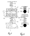
- FIG. 1 there is the one to be examined here Gas exchange valve arrangement in a piston internal combustion engine from a valve body 1 with valve stem 2, which with a Closing spring 3 is connected and via a valve plate 4 in Can be held in the closed position.
- Actuator 5 which consists essentially of a Opening magnet 7 and a closing magnet 6, the Pole faces 8 facing each other and at a distance from each other are arranged.
- an armature 9 is guided to move back and forth, which is firmly connected at one end to an anchor bolt 10 and the other end is via a spring pin 11 on an opening spring 12 supports.
- Fig. 1 the overall arrangement is shown in the closed position, d. H. the armature 9 lies on the pole face of the closing magnet 6 so that the opening spring 12 is compressed by a corresponding amount is.
- the valve body 1 is by the Closing spring 3 held in the closed position.
- a Space VS Between the end the anchor bolt 10 and the end of the valve stem 2 is a Space VS, a so-called valve clearance available, the in practice is in the range of about 0.15 mm.
- the valve clearance VS can change due to thermal influences, in particular Change in length of valve stem 2 when the temperature rises and / or correspondingly rectified change in length of the cylinder head carrying the electromagnetic actuator 5 change in operation within certain limits.
- the opening magnet 7 is depending on the control in the course of the armature movement energized so that the anchor when overshooting its middle position in the influence of the magnetic field building up device and then against the force of the closing spring 3 comes to rest on the pole face 8 of the opening magnet 7. After the stopping time specified by the motor control the opening magnet 7 is de-energized so that the armature 9 can move back into the closed position, captured by the closing magnet and until the next opening process is held.
- the closing spring 3 and the opening spring 12 form the so-called return springs for the armature 5.
- valve clearance compensation through which the valve clearance VS by a corresponding hydraulic Coupling is bridged, there is practically one movement of armature 9 and valve body 1 in the same direction each time the current is switched off on holding magnets.
- the moves at Opening process of the anchor 9 with its anchor bolt 10 and Spring bolts 11 formed guide bolts initially independently under the influence of the accelerating force of the opening spring 12 until the anchor bolt 10 on the free end of the valve stem 2 and then the anchor mass and mass total mass of the valve body is moved.
- the mechanical system shown in Fig. 1 is now to be resolved as an oscillation system in springs and masses. This resolution is shown in Fig. 2.
- the anchor mass m A * to be considered here is formed by the mass of the armature 9 with its anchor bolt 10 and by the mass of the spring bolt 11 and the so-called reduced mass of the opening spring 12.
- the mass m A * is a corresponding mass point shown, while the opening spring 12 is symbolized by its spring constant C12 and the anchor bolt 10 is only shown as a mass-free component.
- the oscillating valve mass m V * is shown as a mass point, the mass of the valve body 1 and the reduced mass of the closing spring 3 including the valve plate 4 also being taken into account here.
- the closing spring 3 is only indicated schematically by its spring constant C3, while the valve stem 2 is shown here as a mass-free component.
- the excitation force P acts on the armature mass m A * .
- the subsystem C3-m V * also performs its own movement, i.e. after the first acceleration ( Position I) the mass m V * swings back by a small amount, but is then driven again in the opening direction when the anchor mass m A * reappears (position II), as shown in the illustration in accordance with. Fig. 3 can be seen.
- the ratio m A * / m V * may only be changed so far with a view to increasing the armature mass that the given sensitivity Sensor technology also the time of impact from the armature movement can still be detected, ie the mass ratio must be specifically changed so that a detectable first rebound of the armature mass m A * takes place.
- the modified electromagnetic actuator for actuation of a gas exchange valve 2 consists essentially of FIG. 1 again from a closing magnet 6 and an opening magnet 7, which are arranged at a distance from each other and between which an armature 9 against the force of return springs, namely an opening spring 12 and a closing spring 3 is guided to move back and forth.
- the closing spring 3 acts directly via one connected to the stem of the gas exchange valve 2 Spring plate 4 a.
- the anchor bolt 10 of the electromagnetic Actuator is separated from the valve stem in the Usually there is a gap in the closed position in the form of so-called valve clearance VS available.
- the opening spring 12 is in turn based on a spring plate 11.1 on the spring bolt 11, so that in the opening movement under the opposing Effect of opening spring 12 and closing spring 3 of the spring bolt 11 on the shaft of the gas exchange valve supports.
- the alternating energization of the electromagnets 6 and 7 of the Actuator takes place via a current regulator assigned to it 14.1, which corresponds to an electronic engine control 14 the specified control programs and depending from the operating data supplied to the engine control, such as Speed, temperature, etc. is controlled. So that will be Gas exchange valve specifically in its open position or its Closed position moves. While it's basically possible one for all actuators on a piston internal combustion engine central current controller, it may be appropriate if each actuator is assigned its own current regulator, connected to a central power supply 14.2 and which is controlled by the engine controller 14.
- a sensor 15 is assigned to the actuator, which detects which enables actuator functions.
- the sensor 15 is here shown schematically.
- the path of the armature 5 can be detected that the respective armature position of the motor controller 14 and / or the current controller 14.1 can be transmitted.
- the Motor control 14 or the current controller 14.1 can then corresponding arithmetic operations, if necessary, also the anchor speed be determined so that depending on the anchor position and / or depending on the anchor speed controlled the energization of the two electromagnets 6, 7 can be.
- closing spring 3 has the higher spring characteristics has, d. H. so is harder to get one to ensure reliable closing of the gas exchange valve.
Landscapes
- Engineering & Computer Science (AREA)
- Mechanical Engineering (AREA)
- General Engineering & Computer Science (AREA)
- Valve Device For Special Equipments (AREA)
- Electromagnets (AREA)
- Magnetically Actuated Valves (AREA)
Abstract
Description
- Fig. 1
- einen schematischen Vertikalschnitt durch eine elektromagnetisch betätigbare Gaswechselventilanordnung,
- Fig. 2
- das aus Fig. 1 abgeleitete Schwingungssystem,
- Fig. 3
- den Verlauf der Geschwindigkeiten von Anker und Ventilkörper bei "kleiner" Ankermasse,
- Fig. 4
- den Verlauf der Geschwindigkeit von Anker und Ventilkörper bei "großer" Ankermasse,
- Fig. 5
- eine Überlagerung der Kurven der Ankerbewegungen bei einer Auslegung gem. Fig. 3 und Fig. 4,
- Fig. 6
- eine Anordnung mit "unsymmetrischer" Auslegung der Rückstellfedern.
Claims (4)
- Gaswechselventilanordnung an einer Kolbenbrennkraftmaschine mit einem mit einer Schließfeder (3) verbundenen Ventilkörper (1) und mit einem elektromagnetischen Aktuator (5), der zwei Elektromagneten (6, 7) aufweist, deren Polflächen (8) gegeneinander ausgerichtet und mit Abstand zueinander angeordnet sind und der einen zwischen den Polflächen (8) hin und her bewegbar geführten Anker (9) mit Führungsbolzen (10, 11) aufweist, die an einem Ende mit dem Ventilkörper (1) und am anderen Ende mit einer Öffnerfeder (12) in Verbindung stehen, wobei zwischen dem Führungsbolzen (10) und dem Ventilkörper (1) ein Ventilspiel (VS) vorhanden ist, und bei dem die schwingende Masse (mA*) des Ankers (5)mindestens das Zweifache der schwingenden Masse (mV*) des Ventilkörpers (1) aufweist.
- Gaswechselventilanordnung nach Anspruch 1, dadurch gekennzeichnet, daß die Öffnerfeder (12) und die Schließfeder (3) gleiche Federkonstanten und gleiche Massen aufweisen.
- Gaswechselventilanordnung nach Anspruch 1 oder 2, dadurch gekennzeichnet, daß die schwingende Masse (mA*) des Ankers (5) nur um so viel gegenüber der schwingenden Masse (mV*) des Ventilkörpers (1) größer ist, daß beim Ventilöffnen das erste Auftreffen des Führungsbolzens (10) auf den Ventilkörper (1) noch als Geschwindigkeitsabfall erfaßbar ist.
- Gaswechselventilanordnung an einer Kolbenbrennkraftmaschine, der mit einem Gaswechselventil (2) und mit zwei im Abstand zueinander angeordneten Elektromagneten (6, 7), zwischen denen ein Anker (9) gegen die Kraft von zwei Rückstellfedern (3, 12) hin und her bewegbar geführt ist, insbesondere Gaswechselventilanordnung nach den Ansprüchen 1 bis 3, dadurch gekennzeichnet, daß die beiden Rückstellfedern (3, 12) unterschiedliche Federkennwerte aufweisen.
Priority Applications (1)
| Application Number | Priority Date | Filing Date | Title |
|---|---|---|---|
| DE20023636U DE20023636U1 (de) | 1999-03-31 | 2000-03-17 | Gaswechselventilanordnung mit elektromagentischem Aktuator |
Applications Claiming Priority (4)
| Application Number | Priority Date | Filing Date | Title |
|---|---|---|---|
| DE19914692 | 1999-03-31 | ||
| DE19914692 | 1999-03-31 | ||
| DE19938297 | 1999-08-12 | ||
| DE19938297A DE19938297A1 (de) | 1999-03-31 | 1999-08-12 | Gaswechselventilanordnung mit elektromagnetischem Aktuator |
Publications (3)
| Publication Number | Publication Date |
|---|---|
| EP1041252A2 true EP1041252A2 (de) | 2000-10-04 |
| EP1041252A3 EP1041252A3 (de) | 2002-08-14 |
| EP1041252B1 EP1041252B1 (de) | 2005-06-01 |
Family
ID=26052696
Family Applications (1)
| Application Number | Title | Priority Date | Filing Date |
|---|---|---|---|
| EP00105716A Expired - Lifetime EP1041252B1 (de) | 1999-03-31 | 2000-03-17 | Gaswechselventilanordnung mit elektromagnetischem Aktuator |
Country Status (4)
| Country | Link |
|---|---|
| US (1) | US6247432B1 (de) |
| EP (1) | EP1041252B1 (de) |
| JP (1) | JP2000310105A (de) |
| AT (1) | ATE296944T1 (de) |
Cited By (3)
| Publication number | Priority date | Publication date | Assignee | Title |
|---|---|---|---|---|
| EP1241324A1 (de) * | 2001-03-17 | 2002-09-18 | Bayerische Motoren Werke Aktiengesellschaft | Verfahren beim Abstellen einer Brennkraftmaschine mit elektromagnetisch betätigten Gaswechselventilen |
| EP1338836A4 (de) * | 2000-10-30 | 2005-03-02 | Mikuni Kogyo Kk | Durch elektromagnetisches stellglied betätigte absperrventil-ansteuervorrichtung |
| US8235011B2 (en) | 2007-08-08 | 2012-08-07 | Daimler Ag | Actuating device |
Families Citing this family (11)
| Publication number | Priority date | Publication date | Assignee | Title |
|---|---|---|---|---|
| DE19951315A1 (de) * | 1999-10-25 | 2001-04-26 | Fev Motorentech Gmbh | Verfahren zum Betrieb einer Kolbenbrennkraftmaschine bei zeitweiligem Funktionsausfall eines elektromagnetischen Ventiltriebs |
| IT1311131B1 (it) * | 1999-11-05 | 2002-03-04 | Magneti Marelli Spa | Metodo per il controllo di attuatori elettromagnetici perl'azionamento di valvole di aspirazione e scarico in motori a |
| JP2002231530A (ja) * | 2001-02-07 | 2002-08-16 | Honda Motor Co Ltd | 電磁アクチュエータ制御装置 |
| DE10207658B4 (de) * | 2002-02-22 | 2008-09-04 | Meta Motoren- Und Energie-Technik Gmbh | Verfahren zum Verkürzen der Öffnungs- und Schließflanke eines Ventils, sowie Ventil |
| US6820598B2 (en) * | 2002-03-22 | 2004-11-23 | Chrysalis Technologies Incorporated | Capillary fuel injector with metering valve for an internal combustion engine |
| FR2842862B1 (fr) * | 2002-07-25 | 2006-03-03 | Procede de determination d'un jeu de distribution a partir d'un couple position/caracteristique electrique | |
| US7165529B2 (en) * | 2004-12-02 | 2007-01-23 | Ford Global Technologies, Llc | Method to control electromechanical valves in a DISI engine |
| FR2922941B1 (fr) * | 2007-10-31 | 2014-05-02 | Valeo Sys Controle Moteur Sas | Procede de determination d'un jeu de distribution au moyen de l'acceleration |
| FI20145100A7 (fi) * | 2014-01-30 | 2015-07-31 | Ixtur Oy | Magneetti |
| DK179123B1 (en) * | 2016-09-16 | 2017-11-13 | Danfoss As | Valve attachment, valve and method for controlling a valve |
| SE542805C2 (sv) * | 2018-07-31 | 2020-07-14 | Hedman Ericsson Patent Ab | Elektriskt aktiverad ventilaktuator för en internförbränningsmotor |
Citations (1)
| Publication number | Priority date | Publication date | Assignee | Title |
|---|---|---|---|---|
| DE19518056A1 (de) | 1995-05-17 | 1996-11-21 | Fev Motorentech Gmbh & Co Kg | Einrichtung zur Steuerung der Ankerbewegung einer elektromagnetischen Schaltanordnung und Verfahren zur Ansteuerung |
Family Cites Families (11)
| Publication number | Priority date | Publication date | Assignee | Title |
|---|---|---|---|---|
| DE3513107A1 (de) * | 1985-04-12 | 1986-10-16 | Fleck, Andreas, 2000 Hamburg | Elektromagnetisch arbeitende stelleinrichtung |
| DE3826978A1 (de) * | 1988-08-09 | 1990-02-15 | Meyer Hans Wilhelm | Elektromagnetisch betaetigbare stellvorrichtung |
| DE19529155B4 (de) * | 1995-08-08 | 2007-05-24 | Fev Motorentechnik Gmbh | Verfahren zur Messung des Ventilspiels an einem durch einen elektromagnetischen Aktuator betätigten Gaswechselventil |
| DE19531437A1 (de) * | 1995-08-26 | 1997-02-27 | Fev Motorentech Gmbh & Co Kg | Verfahren zur Erfassung des Ventilspiels an einem durch einen elektromagnetischen Aktuator betätigten Gaswechselventil |
| KR100248332B1 (ko) * | 1995-12-23 | 2000-04-01 | 정몽규 | 차량의 흡/배기밸브용 개폐장치 |
| DE29604946U1 (de) * | 1996-03-16 | 1997-07-17 | FEV Motorentechnik GmbH & Co. KG, 52078 Aachen | Elektromagnetischer Aktuator für ein Gaswechselventil mit Ventilspielausgleich |
| DE19628860B4 (de) * | 1996-07-17 | 2008-07-31 | Bayerische Motoren Werke Aktiengesellschaft | Elektromagnetische Betätigungsvorrichtung für ein Brennkraftmaschinen-Hubventil |
| DE29615396U1 (de) * | 1996-09-04 | 1998-01-08 | FEV Motorentechnik GmbH & Co. KG, 52078 Aachen | Elektromagnetischer Aktuator mit Aufschlagdämpfung |
| JPH10205314A (ja) * | 1996-12-13 | 1998-08-04 | Fev Motorentechnik Gmbh & Co Kg | ガス交換弁の電磁弁駆動部を制御する方法 |
| JPH11148328A (ja) * | 1997-11-12 | 1999-06-02 | Fuji Heavy Ind Ltd | 電磁駆動バルブの開閉時期検出装置 |
| DE19801396C1 (de) * | 1998-01-16 | 1999-03-04 | Daimler Benz Ag | Betätigungsvorrichtung für ein Gaswechselventil in einer Brennkraftmaschine |
-
2000
- 2000-03-17 AT AT00105716T patent/ATE296944T1/de not_active IP Right Cessation
- 2000-03-17 EP EP00105716A patent/EP1041252B1/de not_active Expired - Lifetime
- 2000-03-30 US US09/539,437 patent/US6247432B1/en not_active Expired - Fee Related
- 2000-03-30 JP JP2000094187A patent/JP2000310105A/ja not_active Withdrawn
Patent Citations (1)
| Publication number | Priority date | Publication date | Assignee | Title |
|---|---|---|---|---|
| DE19518056A1 (de) | 1995-05-17 | 1996-11-21 | Fev Motorentech Gmbh & Co Kg | Einrichtung zur Steuerung der Ankerbewegung einer elektromagnetischen Schaltanordnung und Verfahren zur Ansteuerung |
Cited By (4)
| Publication number | Priority date | Publication date | Assignee | Title |
|---|---|---|---|---|
| EP1338836A4 (de) * | 2000-10-30 | 2005-03-02 | Mikuni Kogyo Kk | Durch elektromagnetisches stellglied betätigte absperrventil-ansteuervorrichtung |
| US6976667B2 (en) | 2000-10-30 | 2005-12-20 | Mikuni Corporation | Opening-closing valve driving apparatus operated by electromagnetic actuator |
| EP1241324A1 (de) * | 2001-03-17 | 2002-09-18 | Bayerische Motoren Werke Aktiengesellschaft | Verfahren beim Abstellen einer Brennkraftmaschine mit elektromagnetisch betätigten Gaswechselventilen |
| US8235011B2 (en) | 2007-08-08 | 2012-08-07 | Daimler Ag | Actuating device |
Also Published As
| Publication number | Publication date |
|---|---|
| ATE296944T1 (de) | 2005-06-15 |
| JP2000310105A (ja) | 2000-11-07 |
| EP1041252B1 (de) | 2005-06-01 |
| US6247432B1 (en) | 2001-06-19 |
| EP1041252A3 (de) | 2002-08-14 |
Similar Documents
| Publication | Publication Date | Title |
|---|---|---|
| DE19518056B4 (de) | Einrichtung zur Steuerung der Ankerbewegung einer elektromagnetischen Schaltanordnung und Verfahren zur Ansteuerung | |
| DE19735375C2 (de) | Magnetventil, insbesondere für Ein- und Auslaßventile von Brennkraftmaschinen | |
| EP0405189B1 (de) | Elektromagnetisch arbeitende Stelleinrichtung | |
| DE19739840C2 (de) | Verfahren zur Steuerung einer elektromagnetisch betätigbaren Stellvorrichtung, insbesondere eines Ventils für Brennkraftmaschinen | |
| DE19640659B4 (de) | Verfahren zur Betätigung eines elektromagnetischen Aktuators mit Beeinflussung des Spulenstroms während der Ankerbewegung | |
| EP1041252B1 (de) | Gaswechselventilanordnung mit elektromagnetischem Aktuator | |
| EP0973178B1 (de) | Verfahren zur Bewegungssteuerung eines Ankers eines elektromagnetischen Aktuators | |
| DE29703585U1 (de) | Elektromagnetischer Aktuator mit magnetischer Auftreffdämpfung | |
| DE19623698A1 (de) | Verfahren zur Steuerung der Antriebe von Hubventilen an einer Kolbenbrennkraftmaschine | |
| DE69908057T2 (de) | Elektromagnetischer Ventil-Aktuator | |
| WO1998010175A1 (de) | Elektromagnetischer aktuator mit aufschlagdämpfung | |
| DE19529155B4 (de) | Verfahren zur Messung des Ventilspiels an einem durch einen elektromagnetischen Aktuator betätigten Gaswechselventil | |
| DE19530121A1 (de) | Verfahren zur Reduzierung der Auftreffgeschwindigkeit eines Ankers an einem elektromagnetischen Aktuator | |
| DE19922971A1 (de) | Verfahren zur Inbetriebnahme eines elektromagnetischen Aktuators zur Betätigung eines Gaswechselventils an einer Kolbenbrennkraftmaschine | |
| DE19651846B4 (de) | Verfahren zur elektromagnetischen Betätigung eines Gaswechselventils ohne Polflächenberührung | |
| DE19641244B4 (de) | Verfahren zur Justierung eines elektromagnetischen Aktuators | |
| EP0973177B1 (de) | Verfahren zur Bewegungssteuerung eines Ankers eines elektromagnetischen Aktuators | |
| DE19521078B4 (de) | Energiesparende elektromagnetische Schaltanordnung | |
| EP1101016B1 (de) | Verfahren zur endlagenansteuerung eines durch einen elektromagnetischen aktuator betätigten gaswechselventils an einer kolbenbrennkraftmaschine | |
| DE10019739A1 (de) | Verfahren zur Endlagenansteuerung eines durch einen elektromagnetischen Aktuator betätigten Gaswechselventils an einer Kolbenbrennkraftmaschine | |
| DE19909109A1 (de) | Verfahren zur Erfassung der Ankerbewegung an einem elektromagnetischen Aktuator | |
| DE19723405A1 (de) | Verfahren zur Steuerung eines elektromagnetischen Ventilbetriebes für ein Gaswechselventil | |
| DE19938297A1 (de) | Gaswechselventilanordnung mit elektromagnetischem Aktuator | |
| EP3346121B1 (de) | Magnetventil für ein kraftstoffeinspritzsystem und kraftstoffhochdruckpumpe | |
| DE10325706B4 (de) | Verfahren zur Steuerung der Bewegung eines Ankers eines elektromagnetischen Aktuators |
Legal Events
| Date | Code | Title | Description |
|---|---|---|---|
| PUAI | Public reference made under article 153(3) epc to a published international application that has entered the european phase |
Free format text: ORIGINAL CODE: 0009012 |
|
| AK | Designated contracting states |
Kind code of ref document: A2 Designated state(s): AT BE CH CY DE DK ES FI FR GB GR IE IT LI LU MC NL PT SE |
|
| AX | Request for extension of the european patent |
Free format text: AL;LT;LV;MK;RO;SI |
|
| PUAL | Search report despatched |
Free format text: ORIGINAL CODE: 0009013 |
|
| AK | Designated contracting states |
Kind code of ref document: A3 Designated state(s): AT BE CH CY DE DK ES FI FR GB GR IE IT LI LU MC NL PT SE |
|
| AX | Request for extension of the european patent |
Free format text: AL;LT;LV;MK;RO;SI |
|
| RIC1 | Information provided on ipc code assigned before grant |
Free format text: 7F 01L 9/04 A, 7F 16K 31/02 B, 7H 01F 7/13 B, 7H 01F 7/17 B |
|
| 17P | Request for examination filed |
Effective date: 20030205 |
|
| AKX | Designation fees paid |
Designated state(s): AT BE CH CY DE DK ES FI FR GB GR IE IT LI LU MC NL PT SE |
|
| 17Q | First examination report despatched |
Effective date: 20030717 |
|
| GRAP | Despatch of communication of intention to grant a patent |
Free format text: ORIGINAL CODE: EPIDOSNIGR1 |
|
| GRAS | Grant fee paid |
Free format text: ORIGINAL CODE: EPIDOSNIGR3 |
|
| GRAA | (expected) grant |
Free format text: ORIGINAL CODE: 0009210 |
|
| AK | Designated contracting states |
Kind code of ref document: B1 Designated state(s): AT BE CH CY DE DK ES FI FR GB GR IE IT LI LU MC NL PT SE |
|
| PG25 | Lapsed in a contracting state [announced via postgrant information from national office to epo] |
Ref country code: IT Free format text: LAPSE BECAUSE OF FAILURE TO SUBMIT A TRANSLATION OF THE DESCRIPTION OR TO PAY THE FEE WITHIN THE PRESCRIBED TIME-LIMIT;WARNING: LAPSES OF ITALIAN PATENTS WITH EFFECTIVE DATE BEFORE 2007 MAY HAVE OCCURRED AT ANY TIME BEFORE 2007. THE CORRECT EFFECTIVE DATE MAY BE DIFFERENT FROM THE ONE RECORDED. Effective date: 20050601 Ref country code: IE Free format text: LAPSE BECAUSE OF FAILURE TO SUBMIT A TRANSLATION OF THE DESCRIPTION OR TO PAY THE FEE WITHIN THE PRESCRIBED TIME-LIMIT Effective date: 20050601 Ref country code: GB Free format text: LAPSE BECAUSE OF FAILURE TO SUBMIT A TRANSLATION OF THE DESCRIPTION OR TO PAY THE FEE WITHIN THE PRESCRIBED TIME-LIMIT Effective date: 20050601 Ref country code: NL Free format text: LAPSE BECAUSE OF FAILURE TO SUBMIT A TRANSLATION OF THE DESCRIPTION OR TO PAY THE FEE WITHIN THE PRESCRIBED TIME-LIMIT Effective date: 20050601 Ref country code: FI Free format text: LAPSE BECAUSE OF FAILURE TO SUBMIT A TRANSLATION OF THE DESCRIPTION OR TO PAY THE FEE WITHIN THE PRESCRIBED TIME-LIMIT Effective date: 20050601 |
|
| REG | Reference to a national code |
Ref country code: GB Ref legal event code: FG4D Free format text: NOT ENGLISH |
|
| REG | Reference to a national code |
Ref country code: CH Ref legal event code: EP |
|
| REG | Reference to a national code |
Ref country code: IE Ref legal event code: FG4D Free format text: LANGUAGE OF EP DOCUMENT: GERMAN |
|
| REF | Corresponds to: |
Ref document number: 50010429 Country of ref document: DE Date of ref document: 20050707 Kind code of ref document: P |
|
| PG25 | Lapsed in a contracting state [announced via postgrant information from national office to epo] |
Ref country code: GR Free format text: LAPSE BECAUSE OF FAILURE TO SUBMIT A TRANSLATION OF THE DESCRIPTION OR TO PAY THE FEE WITHIN THE PRESCRIBED TIME-LIMIT Effective date: 20050901 Ref country code: SE Free format text: LAPSE BECAUSE OF FAILURE TO SUBMIT A TRANSLATION OF THE DESCRIPTION OR TO PAY THE FEE WITHIN THE PRESCRIBED TIME-LIMIT Effective date: 20050901 Ref country code: DK Free format text: LAPSE BECAUSE OF FAILURE TO SUBMIT A TRANSLATION OF THE DESCRIPTION OR TO PAY THE FEE WITHIN THE PRESCRIBED TIME-LIMIT Effective date: 20050901 |
|
| PG25 | Lapsed in a contracting state [announced via postgrant information from national office to epo] |
Ref country code: ES Free format text: LAPSE BECAUSE OF FAILURE TO SUBMIT A TRANSLATION OF THE DESCRIPTION OR TO PAY THE FEE WITHIN THE PRESCRIBED TIME-LIMIT Effective date: 20050912 |
|
| PG25 | Lapsed in a contracting state [announced via postgrant information from national office to epo] |
Ref country code: PT Free format text: LAPSE BECAUSE OF FAILURE TO SUBMIT A TRANSLATION OF THE DESCRIPTION OR TO PAY THE FEE WITHIN THE PRESCRIBED TIME-LIMIT Effective date: 20051107 |
|
| NLV1 | Nl: lapsed or annulled due to failure to fulfill the requirements of art. 29p and 29m of the patents act | ||
| GBV | Gb: ep patent (uk) treated as always having been void in accordance with gb section 77(7)/1977 [no translation filed] |
Effective date: 20050601 |
|
| REG | Reference to a national code |
Ref country code: IE Ref legal event code: FD4D |
|
| PG25 | Lapsed in a contracting state [announced via postgrant information from national office to epo] |
Ref country code: AT Free format text: LAPSE BECAUSE OF NON-PAYMENT OF DUE FEES Effective date: 20060317 |
|
| PG25 | Lapsed in a contracting state [announced via postgrant information from national office to epo] |
Ref country code: BE Free format text: LAPSE BECAUSE OF NON-PAYMENT OF DUE FEES Effective date: 20060331 Ref country code: CH Free format text: LAPSE BECAUSE OF NON-PAYMENT OF DUE FEES Effective date: 20060331 Ref country code: MC Free format text: LAPSE BECAUSE OF NON-PAYMENT OF DUE FEES Effective date: 20060331 Ref country code: LU Free format text: LAPSE BECAUSE OF NON-PAYMENT OF DUE FEES Effective date: 20060331 Ref country code: LI Free format text: LAPSE BECAUSE OF NON-PAYMENT OF DUE FEES Effective date: 20060331 |
|
| PLBE | No opposition filed within time limit |
Free format text: ORIGINAL CODE: 0009261 |
|
| STAA | Information on the status of an ep patent application or granted ep patent |
Free format text: STATUS: NO OPPOSITION FILED WITHIN TIME LIMIT |
|
| 26N | No opposition filed |
Effective date: 20060302 |
|
| EN | Fr: translation not filed | ||
| REG | Reference to a national code |
Ref country code: CH Ref legal event code: PL |
|
| BERE | Be: lapsed |
Owner name: FEV MOTORENTECHNIK G.M.B.H. Effective date: 20060331 |
|
| PGFP | Annual fee paid to national office [announced via postgrant information from national office to epo] |
Ref country code: DE Payment date: 20080325 Year of fee payment: 9 |
|
| PG25 | Lapsed in a contracting state [announced via postgrant information from national office to epo] |
Ref country code: FR Free format text: LAPSE BECAUSE OF FAILURE TO SUBMIT A TRANSLATION OF THE DESCRIPTION OR TO PAY THE FEE WITHIN THE PRESCRIBED TIME-LIMIT Effective date: 20050601 Ref country code: CY Free format text: LAPSE BECAUSE OF FAILURE TO SUBMIT A TRANSLATION OF THE DESCRIPTION OR TO PAY THE FEE WITHIN THE PRESCRIBED TIME-LIMIT Effective date: 20050601 |
|
| PG25 | Lapsed in a contracting state [announced via postgrant information from national office to epo] |
Ref country code: DE Free format text: LAPSE BECAUSE OF NON-PAYMENT OF DUE FEES Effective date: 20091001 |