EP1041184A2 - Dispositif pour controler des nappes de fils dans des machines à tricoter, à tisser ou à prépararer le chaine - Google Patents
Dispositif pour controler des nappes de fils dans des machines à tricoter, à tisser ou à prépararer le chaine Download PDFInfo
- Publication number
- EP1041184A2 EP1041184A2 EP00105989A EP00105989A EP1041184A2 EP 1041184 A2 EP1041184 A2 EP 1041184A2 EP 00105989 A EP00105989 A EP 00105989A EP 00105989 A EP00105989 A EP 00105989A EP 1041184 A2 EP1041184 A2 EP 1041184A2
- Authority
- EP
- European Patent Office
- Prior art keywords
- laser
- lasers
- receivers
- line
- receiver
- Prior art date
- Legal status (The legal status is an assumption and is not a legal conclusion. Google has not performed a legal analysis and makes no representation as to the accuracy of the status listed.)
- Withdrawn
Links
- 238000009940 knitting Methods 0.000 title claims abstract description 11
- 238000012544 monitoring process Methods 0.000 title claims abstract description 11
- 238000009941 weaving Methods 0.000 title claims abstract description 10
- 238000012545 processing Methods 0.000 claims description 7
- 230000003287 optical effect Effects 0.000 claims description 4
- 238000009434 installation Methods 0.000 claims 2
- 230000004888 barrier function Effects 0.000 description 55
- 239000004753 textile Substances 0.000 description 7
- 108010076504 Protein Sorting Signals Proteins 0.000 description 6
- 238000011156 evaluation Methods 0.000 description 6
- 230000003111 delayed effect Effects 0.000 description 5
- 230000005540 biological transmission Effects 0.000 description 3
- 238000005259 measurement Methods 0.000 description 3
- 238000001514 detection method Methods 0.000 description 2
- 230000005405 multipole Effects 0.000 description 2
- 238000004804 winding Methods 0.000 description 2
- 230000001934 delay Effects 0.000 description 1
- 239000004744 fabric Substances 0.000 description 1
- 239000000835 fiber Substances 0.000 description 1
- 238000000034 method Methods 0.000 description 1
- 238000012986 modification Methods 0.000 description 1
- 230000004048 modification Effects 0.000 description 1
- 239000002245 particle Substances 0.000 description 1
- 230000035945 sensitivity Effects 0.000 description 1
Images


Classifications
-
- D—TEXTILES; PAPER
- D03—WEAVING
- D03D—WOVEN FABRICS; METHODS OF WEAVING; LOOMS
- D03D51/00—Driving, starting, or stopping arrangements; Automatic stop motions
- D03D51/18—Automatic stop motions
- D03D51/20—Warp stop motions
- D03D51/28—Warp stop motions electrical
-
- D—TEXTILES; PAPER
- D02—YARNS; MECHANICAL FINISHING OF YARNS OR ROPES; WARPING OR BEAMING
- D02H—WARPING, BEAMING OR LEASING
- D02H13/00—Details of machines of the preceding groups
- D02H13/02—Stop motions
- D02H13/04—Stop motions responsive to breakage, slackness, or excessive tension of threads, with detectors for individual threads or small groups of threads
- D02H13/08—Stop motions responsive to breakage, slackness, or excessive tension of threads, with detectors for individual threads or small groups of threads electrical
-
- D—TEXTILES; PAPER
- D04—BRAIDING; LACE-MAKING; KNITTING; TRIMMINGS; NON-WOVEN FABRICS
- D04B—KNITTING
- D04B35/00—Details of, or auxiliary devices incorporated in, knitting machines, not otherwise provided for
- D04B35/10—Indicating, warning, or safety devices, e.g. stop motions
- D04B35/14—Indicating, warning, or safety devices, e.g. stop motions responsive to thread breakage
- D04B35/16—Indicating, warning, or safety devices, e.g. stop motions responsive to thread breakage with detectors associated with a series of threads
Definitions
- the invention relates to a system for monitoring thread groups in knitting, weaving or warp preparation machines, with at least two lasers each emitting a laser beam and at least two recipients, each with at least one Laser beam strikes.
- threads are produced, rolled up, and processed into fabric on weaving or knitting machines. Both at Warp preparation machines as well as weaving and knitting machines A large number of threads run in parallel in sets of threads. Here it happens that one of the threads breaks. It is important, that then the broken thread is recognized as quickly as possible, so the appropriate machine can be stopped to prevent that scrap is produced.
- laser light barrier systems are in generally two individual laser light barriers in pairs assigned, with each transmitter and each receiver one individual light barrier with its own signal-carrying line and with a control unit for generating and evaluating the respective measurement signals is connected.
- the control unit for the In turn, light barriers are controlled by a controller Textile machine connected to this upon detection to turn off a broken thread.
- An arrangement of a such a laser light barrier system is schematic in Fig. 1A reproduced.
- the use of mapped Laser light barriers for monitoring a thread do not increase only the number of laser light barriers to be used, but also the amount of required signal-carrying lines to the Transmitters and receivers of the laser light barriers.
- the cables and routings are only on site at End customers relocated. Prefabricated in the right length, Multi-core cables cannot be used because of the different Textile machines are built very differently. The cable lengths are used for reasons of economy in warehousing held in 10-meter pieces. When laying there are always unsightly cable loops that are expensive must be accommodated.
- DE 197 22 701 A1 provides a device for Monitor a variety of threads before using multiple detector devices (Light barriers) via a common bus line can be controlled by a control device.
- This bus line is with the lasers of the light barriers as well connected to the receivers (no separate cables), and the lasers are activated in a first signal phase, and received signals are transmitted in a second signal phase.
- Such a solution with a bus line is available from much larger light barrier systems with which entire thread groups if only because lasers are used here are not monitored and the receiver are too far apart to to be controlled via a common bus line.
- Threads in a textile machine require signals individual transmitter-receiver pairs of a light barrier can be distinguished to detect. This way, for example Component tolerances of the transmitter and receiver are taken into account.
- individual light barriers in the Pulse mode controlled, so the influence of extraneous light to suppress or reduce.
- This task is carried out by a system for monitoring thread groups solved in knitting, weaving or warp preparation machines, the at least two lasers each emitting a laser beam and has at least two receivers, on each of which a laser beam strikes, with the laser by control signals over a common line, separated from the receivers and / or the receiver output signals via a common, Give up the line separate from the lasers.
- Another solution to the task is a monitoring system a group of threads in knitting, weaving or warp preparation machines with a transmitter that emits a laser beam and at least one receiver onto which the laser beam at least partially strikes, the one emitted by the laser Laser beam through an optical device in at least two Partial beams is split.
- the above first variant of the invention is advantageously designed such that that all lasers have a first common line are controlled and all receivers via their output signals submit a second common line, using either the assignment the control signals to a transmitter or the assignment of the output signals to a receiver via a coding of the Signals.
- the lasers or the receivers are preferably replaced by a Clock signal driven, the individual transmitter or receiver encoded in the clock signal by a predetermined time sequence are.
- the lasers and / or the receivers are preferably at least partially connected in series and the control signals and / or the output signals each run through an allocation unit, which is suitable for each transmitter and / or receiver Generates signal and passes the signal modified so that the following sender and / or receiver does it for him Process ("recognize") the appropriate signal and for the one following it Transmitter or receiver in the same way a signal can pass on, etc.
- the allocation unit be a delay unit.
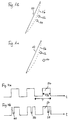
- Figure 1B schematically shows a common arrangement of two one Thread group 10 monitoring laser beams 12 and 14. Tears Thread 16 of the thread sheet 10, it moves into the area of the two laser light beams. If these are both within one certain time (50 ms to 500 ms) interrupted, so there the system for monitoring the thread group sends a signal to the Textile machine to stop them. With this arrangement the two laser light beams run at the same distance the thread cluster 10.
- FIG. 1C shows a further possible arrangement of the laser light beams 12 and 14 according to an aspect of the present invention.
- the second laser light beam 14 is wider away from the thread sheet 10 as the first laser light beam 12. If a thread 16 breaks, it first interrupts the first Laser light beam 12, and only then the second laser light beam 14. This gives you another, more reliable one Criterion to switch off the machine, it does not have to only both laser beams are interrupted, but the first one Laser light beam 12 must be interrupted before the second laser beam (weakened).
- FIG. 2A shows a common arrangement of a laser 18 with optical components and a receiver 20 including optical Components.
- a laser source 22 sends a laser beam 23 made of an aperture 24 with an opening 25 meets.
- the laser beam passing through the opening 25 27 passes through a lens 26.
- the beam 27 passes through the area the light barrier and then hits the receiver 20 first on a lens 28, which focuses it on a sensor 30.
- FIG. 2B now shows an embodiment of the invention. Also here a laser beam 23 is emitted by the laser source 22. This meets an aperture 32 with two openings 34 and 36. A first partial jet 38 runs through the opening 36, and a second partial beam 40 through the opening 34. Here too the two partial beams 38 and 40 leave the laser via one Lens 26, pass through the area of the light barrier and hit on the lens 28 of the receiver 20, from which it points to the sensor 30 to be focused.
- the two partial beams 38 and 40 are oriented as the two laser light beams 12 and 14 in Figure 1B or so in Figure 1C.
- a single laser 18 can handle the laser beams for two light barriers. This will not only Cabling effort halved for the lines, it must be for a variant of the invention in which the Rays are arranged as shown in Figure 1c, only a laser and a receiver can be used and adjusted.
- a transmitter and a receiver a light barrier according to the invention arranged so that the split laser beam 23, i.e. H. its partial beams 38 and 40, are detected by the receiver. Since the two Partial beams 38 and 40 hit the receiver at the same time, are two pulses with a time interval from the receiver detects when a broken thread the two partial beams 38 and 40 interrupts. The time interval between the two detected pulses is determined by the distance between the two partial beams 38 and 40 and the speed of the partial beams 38 and 40 interrupting thread. The amplitude of the two Detected pulses depend on the diameter of the thread the partial beams 38 and 40 interrupts.
- the arrangement of the two Partial beams 38 and 40 corresponds to an arrangement which with the Arrangement of the laser light beams 12 and 14 from Figure 1C comparable is. This means that the two partial beams 38 and 40 are different spaced from a group of threads to be monitored have to be. Since there is only one receiver to detect the two Partial beams 38 and 40 is used is an evaluation of the Sequence of interruptions of partial beams 38 and 40 not possible due to a broken thread.
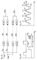
- FIG. 3 Another embodiment of the invention is shown in FIG. 3.
- Four Lasers L1, L2, L3 and L4 are connected via a common line 42 controlled and emit laser beams 44, 46, 48 and 50, the hit the receivers E1, E2, E3 and E4. Give the latter their output signals via a common line 52.
- the two lines 42 and 52 are separated from each other. Frequently will be limited to two lasers over one to control common line, as some technical characteristics the light barrier and its sensitivity setting, Level display, noise display when connected in parallel are coupled together.
- the signals passed over lines 42 and 52 contain information about which of the four light barriers they are assigned.
- the coding and assignment of the signals can be such that it takes place on the laser side, the signal e.g. not all lasers L1 to L4 activated at the same time.
- the coding can also be done on the receiver side. In In this case, all lasers L1 to L4 are activated at the same time, however, the evaluation electronics in the control unit recognize on the basis the coding in the receiver analogous to the coding on the Transmitter side, which light barrier and thus which output signal is relevant.
- the coding may look like the laser or the receivers are controlled by a clock signal, such as it is shown in Figure 4A without coding.
- Clock signal from positive rectangular pulses 54, each of which have half the length of a clock period T.
- the signal is encoded in FIG. 4B.
- a time Interruption 58 in the front of the rectangular pulse 54 the laser Go to L1, a break a little further back 56 the laser L2, and the laser far behind Interrupt the laser L4 of Figure 3.
- Other variants of the Coding is conceivable, for example this can be a clock signal designated regular signal also, according to a predetermined Time sequence must be coded.
- the lasers or receivers have each via electronic means to "recognize" the coding and to respond to the coding so that the Computers processing receiver signals each have information receives which measurement signal belongs to which light barrier.
- the result of this embodiment is that the decoders of the individual laser L1 to L4 or the receiver E1 to E4, which the Recognize coding, cannot be identical, since yes each laser or receiver responds to a different coding got to.
- FIG. 5 shows another way in which all lasers and receivers including their electronic control means can be identical.
- a clock signal 66 with rectangular pulses 68 like that shown in Figure 4A becomes active via a line to a unit 70 Distribution directed.
- This unit can be, for example Flip-flop or a ring counter.
- the unit 70 now distributes the clock signal to the two lasers L1 and L2 so that each second rectangular pulse 68 is supplied to laser L1, and each other rectangular pulses are fed to the laser L2.
- To an ordinary distribution runs to the active distribution unit 70 Clock signal over a common line, which then turns on the lines leading to lasers L1 and L2 are distributed. Since this distribution takes place in the vicinity of the laser, it is reduced the amount of cabling required for the lines considerable here too.
- Decoding logic can also be used instead of the unit 70 become. This becomes pulses such as that in Fig. 4B shown, and it decodes and routes the corresponding signals to the individual lasers.
- the lasers L1, L2, L3 and Ln, the laser light beams, are shown 72, 74, 76 and 78 to receivers E1, E2, E3 and En send out.
- Each of the lasers L1, L2, L3 and Ln is located a delay unit 80, 82, 84 and 86, respectively Rectangular pulse 88 is supplied to laser L1 via line 90.
- the laser L1 is controlled accordingly.
- the delay unit 80 delays the square pulse 88 and sends it delayed rectangular pulse over line 92 to laser L2. This is delayed due to the delayed rectangular pulse activated.
- the rectangular pulse 88 further delayed and is via line 94 to the laser L3 fed, which is activated later in time.
- the laser Ln is activated.
- the lasers L1 to Ln are therefore in Series switched.
- the receivers E1 to En are parallel switched, an evaluation unit can due to the time Sequence of signals an assignment by the receiver output signals to the individual recipients make.
- time delay elements can also be used on the receiver side or coding elements can be provided to the signals of each Distinguish between light barriers.
- signal processing units 80 ', 82 ', 84' and 86 ' are used, which consist of a corresponding one Cable 90, 92, 94 and 96 fed signal sequence SF1, SF2, SF3 and SF4 each have a first signal to control a use the assigned laser L1, L2, L3 or L4 and the remaining signals of the respective signal sequences SF1, SF2, SF3 and SF4 to a correspondingly assigned other Forward laser.
- cable 90 is preferred from a control unit for the laser light barrier system according to the invention after a start pulse SD a first signal sequence SF1 sent to the first laser L1.
- the number of each corresponds to signals encompassed by the first signal sequence SF1 the number of lasers in a light barrier system according to the invention the embodiment of Figure 6B can be used. Since there are four lasers in the example shown in FIG. 6B L1, L2, L3 and L4 are used, comprises the first signal sequence SF1 four individual signals, preferably four individual transmit pulses SP1, SP2, SP3 and SP4.
- the first signal processing unit 80 'for the first laser L1 uses the first transmit pulse SP1 to drive laser L1 so that it emits a laser beam delivers.
- the start pulse SP received via line 90 and the Transmit pulses SP2, SP3 and SP4 are sent to the signal processor Unit 82 'for laser L2 forwarded via line 92.
- the signal processing Unit 84 uses the third transmission case SP3 to transmit the To control and direct laser L3 to emit a laser beam via line 96 the start pulse SP and the fourth transmit pulse SP4 to the signal processing unit 86 'for the laser L4 further, which is initiated by means of the fourth transmission pulse SP4, to deliver a laser beam.
- 90 start pulses together with a following corresponding signal sequence continuously supplied.
- Figure 7a shows another possible arrangement. This exists consisting of two double light barrier systems, each with a laser L1 and a laser L2, the laser light beams 96, 98, 100, 102 send to receivers E1, E2, E3 and E4.
- the laser L1 of the first double light barrier system and the laser L2 of the second Double light barrier systems are via a common line 104 controlled. Accordingly, the second laser L2 of the first double light barrier system and the first laser L1 of the second double light barrier system via a common line 106 controlled.
- the receivers E1 and E2 of the first double light barrier system give their output signals over a common line 108 and the receivers E3 and E4 des second double light barrier system give their signals via a common line 110 from. So here, too, halves required wiring effort for the lines the state of the art, in which all lasers and receivers each can be controlled via a line.
- FIG. 7B shows the control signals that are sent via the lines 104 and 106 are supplied.
- the control signals exist each from a rectangular pulse 112 with a period T is fed, and its length is a quarter of this period is. This is shown in the lower part of Figure 7B.
- This lower signal is used for control via the line 104, the upper signal is supplied via line 106.
- the upper signal has the same shape as the lower signal is but offset in time by half a period. When added together, these signals give a clock signal like that in FIG 4A.
- FIG. 7C An output signal is now shown in FIG. 7C, as described above line 108 or line 110 is output. From the Dash 113 shown in dashed lines becomes a sequence 114 of individual Pulses 115, 116, 117, 118.
- the pulses 115 and 117 can assigned to laser L1 (or to receiver E1 or E3), pulses 116 and 118 can be sent to laser L2 (or the receiver E2 or E4) can be assigned.
- Figure 7A can also be applied to systems with more than two double light barrier systems are transmitted. Signals such as shown in Figure 7B are via a first line fed to one laser of each double light barrier, and the corresponding time delay is carried out via a second line Signals to the second laser of the double light barrier fed. With every double light barrier Signals of the two receivers are carried away via a common line. The saving of the wiring effort required for the cables is therefore larger on the laser side than on the receiving end.
- Delay unit as in Figure 5 in front of lines 104 and 106 may be switched, or line 106 could be in series behind the upper laser L1, which is then connected with a Delay unit is equipped so that the signal initially ran over line 104, over the different Laser, and then as shown in Figure 7A would run the delayed signal on line 106 over which the other lasers can be controlled.
- All double light barriers can have one instead of two receivers single large-area receiver can be used.
Landscapes
- Engineering & Computer Science (AREA)
- Textile Engineering (AREA)
- Spinning Or Twisting Of Yarns (AREA)
- Knitting Machines (AREA)
- Looms (AREA)
- Length Measuring Devices By Optical Means (AREA)
- Optical Communication System (AREA)
Applications Claiming Priority (2)
| Application Number | Priority Date | Filing Date | Title |
|---|---|---|---|
| DE19914478 | 1999-03-30 | ||
| DE1999114478 DE19914478A1 (de) | 1999-03-30 | 1999-03-30 | Anlage zur Überwachung von Fadenscharen in Wirk-. Web- oder Kettvorbereitungsmaschinen |
Publications (2)
| Publication Number | Publication Date |
|---|---|
| EP1041184A2 true EP1041184A2 (fr) | 2000-10-04 |
| EP1041184A3 EP1041184A3 (fr) | 2004-01-14 |
Family
ID=7902990
Family Applications (1)
| Application Number | Title | Priority Date | Filing Date |
|---|---|---|---|
| EP00105989A Withdrawn EP1041184A3 (fr) | 1999-03-30 | 2000-03-27 | Dispositif pour controler des nappes de fils dans des machines à tricoter, à tisser ou à prépararer le chaine |
Country Status (2)
| Country | Link |
|---|---|
| EP (1) | EP1041184A3 (fr) |
| DE (1) | DE19914478A1 (fr) |
Cited By (3)
| Publication number | Priority date | Publication date | Assignee | Title |
|---|---|---|---|---|
| CN103046222A (zh) * | 2012-12-20 | 2013-04-17 | 飞虎科技有限公司 | 基于霍尔传感器的电脑横机掉目检测装置 |
| CN103046221A (zh) * | 2012-12-20 | 2013-04-17 | 飞虎科技有限公司 | 基于槽型光电开关的电脑横机掉目检测装置 |
| CN104233539A (zh) * | 2013-06-07 | 2014-12-24 | 陈友余 | 高速纺纱机激光纱线监控器 |
Family Cites Families (12)
| Publication number | Priority date | Publication date | Assignee | Title |
|---|---|---|---|---|
| US3174046A (en) * | 1961-09-05 | 1965-03-16 | Lindly & Company Inc | Photodynamic monitor for inspecting spun yarns |
| DE2034485A1 (en) * | 1970-07-11 | 1972-01-20 | Sick, Erwin, 7808 Waldkirch | Warp monitor - using divided laser beam under the warps for breakage to be converted to a stop signal |
| DE2034815A1 (en) * | 1970-07-14 | 1972-01-20 | Fa. Erwin Sick, 7808 Waldkirch | Yarn monitor - using laser beam and series of angled mirrors to give photo-electric yarn break detection |
| US3717771A (en) * | 1971-04-02 | 1973-02-20 | Lindly & Co Inc | System for detecting defects in continuous traveling material |
| SE392301B (sv) * | 1974-10-18 | 1977-03-21 | Rydborn S A O | Apparat for avkenning av rorelsen av ett eller flera foremal |
| SE390070B (sv) * | 1975-05-05 | 1976-11-29 | Rydborn S A O | Apparat for indikering av om ett eller flera foremal er i rorelse |
| DE2637195A1 (de) * | 1976-08-18 | 1978-02-23 | Jaeger Emil Kg | Verfahren zur messung sehr kleiner gegenstaende |
| DE3335656C2 (de) * | 1983-09-30 | 1986-08-28 | Protechna Herbst GmbH & Co KG, 8012 Ottobrunn | Vorrichtung zur fotoelektrischen Überwachung einer Kettenwirkmaschine |
| DE19526646C2 (de) * | 1995-07-21 | 2002-10-24 | Akzo Nobel Nv | Verfahren zum Überwachen einer Fadenschar |
| DE19523055A1 (de) * | 1995-06-24 | 1997-01-02 | Akzo Nobel Nv | Verfahren zum Überwachen einer laufenden Fadenschar |
| DE19722701A1 (de) * | 1997-05-30 | 1998-12-03 | Herbst Protechna Gmbh | Vorrichtung und Verfahren zur Überwachung von Fadenscharen |
| FR2784697B1 (fr) * | 1998-10-20 | 2000-12-01 | Setb | Dispositif de tension et de detection de casse des fils de poil, pour tissage du velours faconne |
-
1999
- 1999-03-30 DE DE1999114478 patent/DE19914478A1/de not_active Withdrawn
-
2000
- 2000-03-27 EP EP00105989A patent/EP1041184A3/fr not_active Withdrawn
Cited By (4)
| Publication number | Priority date | Publication date | Assignee | Title |
|---|---|---|---|---|
| CN103046222A (zh) * | 2012-12-20 | 2013-04-17 | 飞虎科技有限公司 | 基于霍尔传感器的电脑横机掉目检测装置 |
| CN103046221A (zh) * | 2012-12-20 | 2013-04-17 | 飞虎科技有限公司 | 基于槽型光电开关的电脑横机掉目检测装置 |
| CN103046222B (zh) * | 2012-12-20 | 2014-12-10 | 飞虎科技有限公司 | 基于霍尔传感器的电脑横机掉目检测装置 |
| CN104233539A (zh) * | 2013-06-07 | 2014-12-24 | 陈友余 | 高速纺纱机激光纱线监控器 |
Also Published As
| Publication number | Publication date |
|---|---|
| DE19914478A1 (de) | 2000-10-19 |
| EP1041184A3 (fr) | 2004-01-14 |
Similar Documents
| Publication | Publication Date | Title |
|---|---|---|
| EP2071363B1 (fr) | Barrière lumineuse et son procédé de fonctionnement | |
| DE4129126C2 (fr) | ||
| EP1544643B1 (fr) | Procédé et dispositif pour la surveillance d'une zone avec plusieurs émetteurs de lumière disposés côte à côte | |
| DE4338978C2 (de) | Verfahren zur Feststellung defekter Lichtsender und/oder Lichtempfänger eines Lichtgitters und Lichtgitter | |
| DE4424537A1 (de) | Verfahren zum Betrieb eines Lichtgitters und Lichtgitter | |
| DE19611195C1 (de) | Verfahren zum Betrieb einer Lichtschrankenanordnung | |
| EP0761585A1 (fr) | Détecteur de fil | |
| DE1907990A1 (de) | Verfahren und Vorrichtung zum Feststellen und Melden von unerwuenschten AEnderungen des Betriebszustandes einer Vielzahl von Garnherstellungseinrichtungen,insbesondere zum Feststellen und Melden von Fadenbruechen bei Textilmaschinen | |
| DE2513356C3 (de) | Photoelektrischer Schußfadenwächter | |
| DE102007031430B4 (de) | Verfahren zum Betrieb eines Lichtgitters und Lichtgitter | |
| EP1041184A2 (fr) | Dispositif pour controler des nappes de fils dans des machines à tricoter, à tisser ou à prépararer le chaine | |
| DE2857592A1 (de) | Fadenbruch-feststellvorrichtung mit mehreren sensoren | |
| DE1296469B (de) | UEberwachungseinrichtung fuer die Zufuhr von quer zu ihrer Laengsrichtung bewegten Faeden | |
| EP0282745A1 (fr) | Procédé et dispositif pour la surveillance de la production et de la qualité aux postes de travail des machines textiles multi-broches | |
| DE20104248U1 (de) | Lichtgitter | |
| EP1903356A1 (fr) | Rideau de lumière | |
| DE3910537C2 (fr) | ||
| DE202006012637U1 (de) | Vorrichtung zum Kollisionsschutz zwischen aufeinanderfolgenden spurgeführten Fahrzeugen | |
| DE20303085U1 (de) | Lichtgitter | |
| DE202005010358U1 (de) | Optoelektronisches Lichtgitter | |
| DE3635140A1 (de) | Optische abtastvorrichtung zur ermittlung einer leerlaufenden vorlagenspule bei einer spinn- oder zwirnmaschine | |
| DE4300581C2 (de) | Vorrichtung zur fotoelektrischen Überwachung | |
| DE2329937C3 (de) | Strahlenschranke | |
| DE202008005619U1 (de) | Kettenwirkmaschine | |
| DE2050508C2 (de) | Vorrichtung zur Überwachung einer Reihe von Fadenstellen einer Spinn- oder Zwirnmaschine auf Fadenbruch |
Legal Events
| Date | Code | Title | Description |
|---|---|---|---|
| PUAI | Public reference made under article 153(3) epc to a published international application that has entered the european phase |
Free format text: ORIGINAL CODE: 0009012 |
|
| AK | Designated contracting states |
Kind code of ref document: A2 Designated state(s): AT BE CH CY DE DK ES FI FR GB GR IE IT LI LU MC NL PT SE |
|
| AX | Request for extension of the european patent |
Free format text: AL;LT;LV;MK;RO;SI |
|
| PUAL | Search report despatched |
Free format text: ORIGINAL CODE: 0009013 |
|
| AK | Designated contracting states |
Kind code of ref document: A3 Designated state(s): AT BE CH CY DE DK ES FI FR GB GR IE IT LI LU MC NL PT SE |
|
| AX | Request for extension of the european patent |
Extension state: AL LT LV MK RO SI |
|
| AKX | Designation fees paid | ||
| REG | Reference to a national code |
Ref country code: DE Ref legal event code: 8566 |
|
| STAA | Information on the status of an ep patent application or granted ep patent |
Free format text: STATUS: THE APPLICATION IS DEEMED TO BE WITHDRAWN |
|
| 18D | Application deemed to be withdrawn |
Effective date: 20040715 |