EP1041184A2 - Device for monitoring yarn webs in knitting, weaving or warp preparation machines - Google Patents
Device for monitoring yarn webs in knitting, weaving or warp preparation machines Download PDFInfo
- Publication number
- EP1041184A2 EP1041184A2 EP00105989A EP00105989A EP1041184A2 EP 1041184 A2 EP1041184 A2 EP 1041184A2 EP 00105989 A EP00105989 A EP 00105989A EP 00105989 A EP00105989 A EP 00105989A EP 1041184 A2 EP1041184 A2 EP 1041184A2
- Authority
- EP
- European Patent Office
- Prior art keywords
- lasers
- laser
- receivers
- signals
- line
- Prior art date
- Legal status (The legal status is an assumption and is not a legal conclusion. Google has not performed a legal analysis and makes no representation as to the accuracy of the status listed.)
- Withdrawn
Links
- 238000009940 knitting Methods 0.000 title claims description 10
- 238000012544 monitoring process Methods 0.000 title claims description 10
- 238000009941 weaving Methods 0.000 title claims description 9
- 238000012545 processing Methods 0.000 claims abstract description 8
- 230000003287 optical effect Effects 0.000 claims description 4
- 238000009434 installation Methods 0.000 claims 2
- 238000012986 modification Methods 0.000 abstract description 2
- 230000004048 modification Effects 0.000 abstract description 2
- 230000004888 barrier function Effects 0.000 description 55
- 239000004753 textile Substances 0.000 description 7
- 108010076504 Protein Sorting Signals Proteins 0.000 description 6
- 238000011156 evaluation Methods 0.000 description 6
- 230000003111 delayed effect Effects 0.000 description 5
- 230000005540 biological transmission Effects 0.000 description 3
- 238000005259 measurement Methods 0.000 description 3
- 238000001514 detection method Methods 0.000 description 2
- 230000005405 multipole Effects 0.000 description 2
- 238000004804 winding Methods 0.000 description 2
- 230000001934 delay Effects 0.000 description 1
- 239000004744 fabric Substances 0.000 description 1
- 239000000835 fiber Substances 0.000 description 1
- 238000000034 method Methods 0.000 description 1
- 239000002245 particle Substances 0.000 description 1
- 230000035945 sensitivity Effects 0.000 description 1
Images


Classifications
-
- D—TEXTILES; PAPER
- D03—WEAVING
- D03D—WOVEN FABRICS; METHODS OF WEAVING; LOOMS
- D03D51/00—Driving, starting, or stopping arrangements; Automatic stop motions
- D03D51/18—Automatic stop motions
- D03D51/20—Warp stop motions
- D03D51/28—Warp stop motions electrical
-
- D—TEXTILES; PAPER
- D02—YARNS; MECHANICAL FINISHING OF YARNS OR ROPES; WARPING OR BEAMING
- D02H—WARPING, BEAMING OR LEASING
- D02H13/00—Details of machines of the preceding groups
- D02H13/02—Stop motions
- D02H13/04—Stop motions responsive to breakage, slackness, or excessive tension of threads, with detectors for individual threads or small groups of threads
- D02H13/08—Stop motions responsive to breakage, slackness, or excessive tension of threads, with detectors for individual threads or small groups of threads electrical
-
- D—TEXTILES; PAPER
- D04—BRAIDING; LACE-MAKING; KNITTING; TRIMMINGS; NON-WOVEN FABRICS
- D04B—KNITTING
- D04B35/00—Details of, or auxiliary devices incorporated in, knitting machines, not otherwise provided for
- D04B35/10—Indicating, warning, or safety devices, e.g. stop motions
- D04B35/14—Indicating, warning, or safety devices, e.g. stop motions responsive to thread breakage
- D04B35/16—Indicating, warning, or safety devices, e.g. stop motions responsive to thread breakage with detectors associated with a series of threads
Definitions
- the invention relates to a system for monitoring thread groups in knitting, weaving or warp preparation machines, with at least two lasers each emitting a laser beam and at least two recipients, each with at least one Laser beam strikes.
- threads are produced, rolled up, and processed into fabric on weaving or knitting machines. Both at Warp preparation machines as well as weaving and knitting machines A large number of threads run in parallel in sets of threads. Here it happens that one of the threads breaks. It is important, that then the broken thread is recognized as quickly as possible, so the appropriate machine can be stopped to prevent that scrap is produced.
- laser light barrier systems are in generally two individual laser light barriers in pairs assigned, with each transmitter and each receiver one individual light barrier with its own signal-carrying line and with a control unit for generating and evaluating the respective measurement signals is connected.
- the control unit for the In turn, light barriers are controlled by a controller Textile machine connected to this upon detection to turn off a broken thread.
- An arrangement of a such a laser light barrier system is schematic in Fig. 1A reproduced.
- the use of mapped Laser light barriers for monitoring a thread do not increase only the number of laser light barriers to be used, but also the amount of required signal-carrying lines to the Transmitters and receivers of the laser light barriers.
- the cables and routings are only on site at End customers relocated. Prefabricated in the right length, Multi-core cables cannot be used because of the different Textile machines are built very differently. The cable lengths are used for reasons of economy in warehousing held in 10-meter pieces. When laying there are always unsightly cable loops that are expensive must be accommodated.
- DE 197 22 701 A1 provides a device for Monitor a variety of threads before using multiple detector devices (Light barriers) via a common bus line can be controlled by a control device.
- This bus line is with the lasers of the light barriers as well connected to the receivers (no separate cables), and the lasers are activated in a first signal phase, and received signals are transmitted in a second signal phase.
- Such a solution with a bus line is available from much larger light barrier systems with which entire thread groups if only because lasers are used here are not monitored and the receiver are too far apart to to be controlled via a common bus line.
- Threads in a textile machine require signals individual transmitter-receiver pairs of a light barrier can be distinguished to detect. This way, for example Component tolerances of the transmitter and receiver are taken into account.
- individual light barriers in the Pulse mode controlled, so the influence of extraneous light to suppress or reduce.
- This task is carried out by a system for monitoring thread groups solved in knitting, weaving or warp preparation machines, the at least two lasers each emitting a laser beam and has at least two receivers, on each of which a laser beam strikes, with the laser by control signals over a common line, separated from the receivers and / or the receiver output signals via a common, Give up the line separate from the lasers.
- Another solution to the task is a monitoring system a group of threads in knitting, weaving or warp preparation machines with a transmitter that emits a laser beam and at least one receiver onto which the laser beam at least partially strikes, the one emitted by the laser Laser beam through an optical device in at least two Partial beams is split.
- the above first variant of the invention is advantageously designed such that that all lasers have a first common line are controlled and all receivers via their output signals submit a second common line, using either the assignment the control signals to a transmitter or the assignment of the output signals to a receiver via a coding of the Signals.
- the lasers or the receivers are preferably replaced by a Clock signal driven, the individual transmitter or receiver encoded in the clock signal by a predetermined time sequence are.
- the lasers and / or the receivers are preferably at least partially connected in series and the control signals and / or the output signals each run through an allocation unit, which is suitable for each transmitter and / or receiver Generates signal and passes the signal modified so that the following sender and / or receiver does it for him Process ("recognize") the appropriate signal and for the one following it Transmitter or receiver in the same way a signal can pass on, etc.
- the allocation unit be a delay unit.
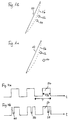
- Figure 1B schematically shows a common arrangement of two one Thread group 10 monitoring laser beams 12 and 14. Tears Thread 16 of the thread sheet 10, it moves into the area of the two laser light beams. If these are both within one certain time (50 ms to 500 ms) interrupted, so there the system for monitoring the thread group sends a signal to the Textile machine to stop them. With this arrangement the two laser light beams run at the same distance the thread cluster 10.
- FIG. 1C shows a further possible arrangement of the laser light beams 12 and 14 according to an aspect of the present invention.
- the second laser light beam 14 is wider away from the thread sheet 10 as the first laser light beam 12. If a thread 16 breaks, it first interrupts the first Laser light beam 12, and only then the second laser light beam 14. This gives you another, more reliable one Criterion to switch off the machine, it does not have to only both laser beams are interrupted, but the first one Laser light beam 12 must be interrupted before the second laser beam (weakened).
- FIG. 2A shows a common arrangement of a laser 18 with optical components and a receiver 20 including optical Components.
- a laser source 22 sends a laser beam 23 made of an aperture 24 with an opening 25 meets.
- the laser beam passing through the opening 25 27 passes through a lens 26.
- the beam 27 passes through the area the light barrier and then hits the receiver 20 first on a lens 28, which focuses it on a sensor 30.
- FIG. 2B now shows an embodiment of the invention. Also here a laser beam 23 is emitted by the laser source 22. This meets an aperture 32 with two openings 34 and 36. A first partial jet 38 runs through the opening 36, and a second partial beam 40 through the opening 34. Here too the two partial beams 38 and 40 leave the laser via one Lens 26, pass through the area of the light barrier and hit on the lens 28 of the receiver 20, from which it points to the sensor 30 to be focused.
- the two partial beams 38 and 40 are oriented as the two laser light beams 12 and 14 in Figure 1B or so in Figure 1C.
- a single laser 18 can handle the laser beams for two light barriers. This will not only Cabling effort halved for the lines, it must be for a variant of the invention in which the Rays are arranged as shown in Figure 1c, only a laser and a receiver can be used and adjusted.
- a transmitter and a receiver a light barrier according to the invention arranged so that the split laser beam 23, i.e. H. its partial beams 38 and 40, are detected by the receiver. Since the two Partial beams 38 and 40 hit the receiver at the same time, are two pulses with a time interval from the receiver detects when a broken thread the two partial beams 38 and 40 interrupts. The time interval between the two detected pulses is determined by the distance between the two partial beams 38 and 40 and the speed of the partial beams 38 and 40 interrupting thread. The amplitude of the two Detected pulses depend on the diameter of the thread the partial beams 38 and 40 interrupts.
- the arrangement of the two Partial beams 38 and 40 corresponds to an arrangement which with the Arrangement of the laser light beams 12 and 14 from Figure 1C comparable is. This means that the two partial beams 38 and 40 are different spaced from a group of threads to be monitored have to be. Since there is only one receiver to detect the two Partial beams 38 and 40 is used is an evaluation of the Sequence of interruptions of partial beams 38 and 40 not possible due to a broken thread.
- FIG. 3 Another embodiment of the invention is shown in FIG. 3.
- Four Lasers L1, L2, L3 and L4 are connected via a common line 42 controlled and emit laser beams 44, 46, 48 and 50, the hit the receivers E1, E2, E3 and E4. Give the latter their output signals via a common line 52.
- the two lines 42 and 52 are separated from each other. Frequently will be limited to two lasers over one to control common line, as some technical characteristics the light barrier and its sensitivity setting, Level display, noise display when connected in parallel are coupled together.
- the signals passed over lines 42 and 52 contain information about which of the four light barriers they are assigned.
- the coding and assignment of the signals can be such that it takes place on the laser side, the signal e.g. not all lasers L1 to L4 activated at the same time.
- the coding can also be done on the receiver side. In In this case, all lasers L1 to L4 are activated at the same time, however, the evaluation electronics in the control unit recognize on the basis the coding in the receiver analogous to the coding on the Transmitter side, which light barrier and thus which output signal is relevant.
- the coding may look like the laser or the receivers are controlled by a clock signal, such as it is shown in Figure 4A without coding.
- Clock signal from positive rectangular pulses 54, each of which have half the length of a clock period T.
- the signal is encoded in FIG. 4B.
- a time Interruption 58 in the front of the rectangular pulse 54 the laser Go to L1, a break a little further back 56 the laser L2, and the laser far behind Interrupt the laser L4 of Figure 3.
- Other variants of the Coding is conceivable, for example this can be a clock signal designated regular signal also, according to a predetermined Time sequence must be coded.
- the lasers or receivers have each via electronic means to "recognize" the coding and to respond to the coding so that the Computers processing receiver signals each have information receives which measurement signal belongs to which light barrier.
- the result of this embodiment is that the decoders of the individual laser L1 to L4 or the receiver E1 to E4, which the Recognize coding, cannot be identical, since yes each laser or receiver responds to a different coding got to.
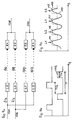
- FIG. 5 shows another way in which all lasers and receivers including their electronic control means can be identical.
- a clock signal 66 with rectangular pulses 68 like that shown in Figure 4A becomes active via a line to a unit 70 Distribution directed.
- This unit can be, for example Flip-flop or a ring counter.
- the unit 70 now distributes the clock signal to the two lasers L1 and L2 so that each second rectangular pulse 68 is supplied to laser L1, and each other rectangular pulses are fed to the laser L2.
- To an ordinary distribution runs to the active distribution unit 70 Clock signal over a common line, which then turns on the lines leading to lasers L1 and L2 are distributed. Since this distribution takes place in the vicinity of the laser, it is reduced the amount of cabling required for the lines considerable here too.
- Decoding logic can also be used instead of the unit 70 become. This becomes pulses such as that in Fig. 4B shown, and it decodes and routes the corresponding signals to the individual lasers.
- the lasers L1, L2, L3 and Ln, the laser light beams, are shown 72, 74, 76 and 78 to receivers E1, E2, E3 and En send out.
- Each of the lasers L1, L2, L3 and Ln is located a delay unit 80, 82, 84 and 86, respectively Rectangular pulse 88 is supplied to laser L1 via line 90.
- the laser L1 is controlled accordingly.
- the delay unit 80 delays the square pulse 88 and sends it delayed rectangular pulse over line 92 to laser L2. This is delayed due to the delayed rectangular pulse activated.
- the rectangular pulse 88 further delayed and is via line 94 to the laser L3 fed, which is activated later in time.
- the laser Ln is activated.
- the lasers L1 to Ln are therefore in Series switched.
- the receivers E1 to En are parallel switched, an evaluation unit can due to the time Sequence of signals an assignment by the receiver output signals to the individual recipients make.
- time delay elements can also be used on the receiver side or coding elements can be provided to the signals of each Distinguish between light barriers.
- signal processing units 80 ', 82 ', 84' and 86 ' are used, which consist of a corresponding one Cable 90, 92, 94 and 96 fed signal sequence SF1, SF2, SF3 and SF4 each have a first signal to control a use the assigned laser L1, L2, L3 or L4 and the remaining signals of the respective signal sequences SF1, SF2, SF3 and SF4 to a correspondingly assigned other Forward laser.
- cable 90 is preferred from a control unit for the laser light barrier system according to the invention after a start pulse SD a first signal sequence SF1 sent to the first laser L1.
- the number of each corresponds to signals encompassed by the first signal sequence SF1 the number of lasers in a light barrier system according to the invention the embodiment of Figure 6B can be used. Since there are four lasers in the example shown in FIG. 6B L1, L2, L3 and L4 are used, comprises the first signal sequence SF1 four individual signals, preferably four individual transmit pulses SP1, SP2, SP3 and SP4.
- the first signal processing unit 80 'for the first laser L1 uses the first transmit pulse SP1 to drive laser L1 so that it emits a laser beam delivers.
- the start pulse SP received via line 90 and the Transmit pulses SP2, SP3 and SP4 are sent to the signal processor Unit 82 'for laser L2 forwarded via line 92.
- the signal processing Unit 84 uses the third transmission case SP3 to transmit the To control and direct laser L3 to emit a laser beam via line 96 the start pulse SP and the fourth transmit pulse SP4 to the signal processing unit 86 'for the laser L4 further, which is initiated by means of the fourth transmission pulse SP4, to deliver a laser beam.
- 90 start pulses together with a following corresponding signal sequence continuously supplied.
- Figure 7a shows another possible arrangement. This exists consisting of two double light barrier systems, each with a laser L1 and a laser L2, the laser light beams 96, 98, 100, 102 send to receivers E1, E2, E3 and E4.
- the laser L1 of the first double light barrier system and the laser L2 of the second Double light barrier systems are via a common line 104 controlled. Accordingly, the second laser L2 of the first double light barrier system and the first laser L1 of the second double light barrier system via a common line 106 controlled.
- the receivers E1 and E2 of the first double light barrier system give their output signals over a common line 108 and the receivers E3 and E4 des second double light barrier system give their signals via a common line 110 from. So here, too, halves required wiring effort for the lines the state of the art, in which all lasers and receivers each can be controlled via a line.
- FIG. 7B shows the control signals that are sent via the lines 104 and 106 are supplied.
- the control signals exist each from a rectangular pulse 112 with a period T is fed, and its length is a quarter of this period is. This is shown in the lower part of Figure 7B.
- This lower signal is used for control via the line 104, the upper signal is supplied via line 106.
- the upper signal has the same shape as the lower signal is but offset in time by half a period. When added together, these signals give a clock signal like that in FIG 4A.
- FIG. 7C An output signal is now shown in FIG. 7C, as described above line 108 or line 110 is output. From the Dash 113 shown in dashed lines becomes a sequence 114 of individual Pulses 115, 116, 117, 118.
- the pulses 115 and 117 can assigned to laser L1 (or to receiver E1 or E3), pulses 116 and 118 can be sent to laser L2 (or the receiver E2 or E4) can be assigned.
- Figure 7A can also be applied to systems with more than two double light barrier systems are transmitted. Signals such as shown in Figure 7B are via a first line fed to one laser of each double light barrier, and the corresponding time delay is carried out via a second line Signals to the second laser of the double light barrier fed. With every double light barrier Signals of the two receivers are carried away via a common line. The saving of the wiring effort required for the cables is therefore larger on the laser side than on the receiving end.
- Delay unit as in Figure 5 in front of lines 104 and 106 may be switched, or line 106 could be in series behind the upper laser L1, which is then connected with a Delay unit is equipped so that the signal initially ran over line 104, over the different Laser, and then as shown in Figure 7A would run the delayed signal on line 106 over which the other lasers can be controlled.
- All double light barriers can have one instead of two receivers single large-area receiver can be used.
Landscapes
- Engineering & Computer Science (AREA)
- Textile Engineering (AREA)
- Length Measuring Devices By Optical Means (AREA)
- Optical Communication System (AREA)
- Spinning Or Twisting Of Yarns (AREA)
- Knitting Machines (AREA)
- Looms (AREA)
Abstract
Description
Die Erfindung betrifft eine Anlage zur Überwachung von Fadenscharen in Wirk-, Web- oder Kettvorbereitungsmaschinen, mit mindestens zwei je einen Laserstrahl aussendenden Lasern und mindestens zwei Empfängern, auf denen jeweils mindestens ein Laserstrahl auftrifft.The invention relates to a system for monitoring thread groups in knitting, weaving or warp preparation machines, with at least two lasers each emitting a laser beam and at least two recipients, each with at least one Laser beam strikes.
In der Textilindustrie werden Fäden erzeugt, aufgerollt, und auf Web- oder Wirkmaschinen zu Stoff verarbeitet. Sowohl bei Kettvorbereitungsmaschinen als auch bei Web- und Wirkmaschinen laufen eine Vielzahl von Fäden parallel in Fadenscharen. Dabei kommt es vor, daß einer der Fäden reißt. Es ist wichtig, daß dann der gerissene Faden möglichst schnell erkannt wird, damit die entsprechende Maschine angehalten werden kann, um zu verhindern, daß Ausschuß produziert wird.In the textile industry, threads are produced, rolled up, and processed into fabric on weaving or knitting machines. Both at Warp preparation machines as well as weaving and knitting machines A large number of threads run in parallel in sets of threads. Here it happens that one of the threads breaks. It is important, that then the broken thread is recognized as quickly as possible, so the appropriate machine can be stopped to prevent that scrap is produced.
Zur Erkennung eines gerissenen Fadens ist es gängig, Lichtschrankensysteme zu verwenden, üblicherweise Laserlichtschranken. Der Laserstrahl wird dabei nahe an der Fadenschar vorbeigeführt, und ein gerissener Faden gelangt in den Laserlichtstrahl oder wird dorthin gelenkt und erzeugt ein Signal in der Auswertelogik. Die Auslenkung des gerissenen Fadens in den Laserlichtstrahl wird bisweilen durch Gebläse unterstützt.To detect a broken thread, it is common to use light barrier systems to be used, usually laser light barriers. The laser beam is guided close to the thread sheet, and a broken thread gets into the laser light beam or is directed there and generates a signal in the Evaluation logic. The deflection of the broken thread into the laser light beam is sometimes supported by fans.
Insbesondere bei fasernden Fäden kann es zu Störungen der Lichtschranke durch in der Luft befindliche Faserteilchen kommen. Um Fehlalarme zu vermeiden, werden daher häufig zwei Laserlichtschranken dicht nebeneinander angeordnet. Um die Textilmaschine abzuschalten, müssen dann beide Laserlichtschranken innerhalb einer definierten Zeit (z.B. 50 ms bis 500 ms) durch den Faden unterbrochen werden. Especially with fibrillating threads it can lead to disturbances of the Light barrier coming through fiber particles in the air. To avoid false alarms, two laser light barriers are therefore often used arranged close to each other. To the textile machine then switch off both laser light barriers within a defined time (e.g. 50 ms to 500 ms) the thread be interrupted.
Dadurch verdoppelt sich die Zahl der notwendigen Laserlichtschranken. Da bei aufwendigeren Maschinen mehrere Fadenscharen zu überwachen sind, ist die Zahl der einzusetzenden Laserlichtschranken hoch.This doubles the number of laser light barriers required. Since several thread coulters in more complex machines The number of laser light barriers to be used must be monitored high.
Bei derartigen bekannten Laserlichtschrankensystemen sind im allgemeinen zwei einzelne Laserlichtschranken paarweise einander zugeordnet, wobei jeder Sender und jeder Empfänger einer einzelnen Lichtschranke mit einer eigenen signalführenden Leitung und mit einem Steuergerät zur Erzeugung und Auswertung der jeweiligen Meßsignale verbunden ist. Das Steuergerät für die Lichtschranken ist wiederum mit einer Steuerung einer zu überwachenden Textilmaschine verbunden, um diese bei einer Detektion eines gerissenen Fadens abzuschalten. Eine Anordnung eines derartigen Laserlichtschrankensystems ist in Fig. 1A schematisch wiedergegeben. Die Verwendung von einander zugeordneten Laserlichtschranken zur Überwachung eines Fadens erhöht nicht nur die Zahl der einzusetzenden Laserlichtschranken, sondern auch die Menge der benötigten signalführenden Leitungen zu den Sendern und den Empfängern der Laserlichtschranken.In such known laser light barrier systems are in generally two individual laser light barriers in pairs assigned, with each transmitter and each receiver one individual light barrier with its own signal-carrying line and with a control unit for generating and evaluating the respective measurement signals is connected. The control unit for the In turn, light barriers are controlled by a controller Textile machine connected to this upon detection to turn off a broken thread. An arrangement of a such a laser light barrier system is schematic in Fig. 1A reproduced. The use of mapped Laser light barriers for monitoring a thread do not increase only the number of laser light barriers to be used, but also the amount of required signal-carrying lines to the Transmitters and receivers of the laser light barriers.
Bei jeder Laserlichtschranke müssen Leitungen zu dem den Laserlichtstrahl aussendenden Laser und zu dem Empfänger hin verlegt werden. Bei Kettvorbereitungsmaschinen, etwa Schärgattern, werden ca. 600 bis 700 m mehrpolige Leitungen, bei Kettenwirkmaschinen werden ca. 150 m mehrpolige Leitungen benötigt. Die jeweils benötigten Leitungslängen verdoppelten sich, wenn zwei Lichtschranken zur Überwachung eines Fadens verwendet werden.For each laser light barrier, lines must be connected to the laser light beam emitting laser and moved to the receiver become. With warp preparation machines, such as warping gates approx. 600 to 700 m multi-pole cables, for warp knitting machines approx. 150 m multi-pole cables are required. The each required cable lengths doubled if two Photoelectric sensors can be used to monitor a thread.
Die Leitungen und Leitungsführungen werden erst vor Ort beim Endkunden verlegt. In der richtigen Länge vorgefertigte, mehradrige Leitungen können nicht verwendet werden, da die verschiedenen Textilmaschinen sehr unterschiedlich gebaut sind. Die Leitungslängen werden aus Gründen der Ökonomie bei der Lagerhaltung in 10-Meter-Stücken vorgehalten. Bei der Verlegung bleiben immer unschöne Leitungsschlaufen übrig, die aufwendig untergebracht werden müssen. The cables and routings are only on site at End customers relocated. Prefabricated in the right length, Multi-core cables cannot be used because of the different Textile machines are built very differently. The cable lengths are used for reasons of economy in warehousing held in 10-meter pieces. When laying there are always unsightly cable loops that are expensive must be accommodated.
Bei Wickel-, Schär-, Spul- oder Zwirnmaschinen ist es auch üblich, jeden einzelnen der unzähligen Fäden durch eine kleine Lichtschranke zu überwachen. Hier muß zwangsläufig für die für die Leitungen erforderliche Verkabelung eine eigene Lösung gefunden werden. Die DE 197 22 701 A1 stellt eine Vorrichtung zum Überwachen einer Vielzahl von Fäden vor, bei der mehrere Detektoreinrichtungen (Lichtschranken) über eine gemeinsame Busleitung von einer Steuereinrichtung angesteuert werden. Diese Busleitung ist sowohl mit den Lasern der Lichtschranken als auch mit den Empfängern verbunden (also keine getrennten Kabel), und in einer ersten Signalphase werden die Laser aktiviert, und empfangene Signale werden in einer zweiten Signalphase übertragen. Eine solche Lösung mit einer Busleitung gibt es bei den wesentlich größeren Lichtschrankensystemen, mit denen ganze Fadenscharen überwacht werden schon deswegen nicht, weil hier Laser und Empfänger einen zu großen Abstand voneinander haben, um über eine gemeinsame Busleitung angesteuert werden zu können.With winding, warping, winding or twisting machines it is also common each of the myriad threads through a small one Monitor light barrier. Here inevitably for those for the cables required wiring found their own solution become. DE 197 22 701 A1 provides a device for Monitor a variety of threads before using multiple detector devices (Light barriers) via a common bus line can be controlled by a control device. This bus line is with the lasers of the light barriers as well connected to the receivers (no separate cables), and the lasers are activated in a first signal phase, and received signals are transmitted in a second signal phase. Such a solution with a bus line is available from much larger light barrier systems with which entire thread groups if only because lasers are used here are not monitored and the receiver are too far apart to to be controlled via a common bus line.
Bei der Verwendung mehrerer Lichtschranken zur Überwachung von Fäden in einer Textilmaschine ist es erforderlich, die Signale einzelner Sender-Empfänger-Paare einer Lichtschranke unterscheidbar zu detektieren. Auf diese Weise werden beispielsweise Bauteiltoleranzen der Sender und Empfänger berücksichtigt. Üblicherweise werden hierfür die einzelnen Lichtschranken im Pulsbetrieb angesteuert, um so auch den Einfluß von Fremdlicht zu unterdrücken oder zu reduzieren.When using multiple light barriers to monitor Threads in a textile machine require signals individual transmitter-receiver pairs of a light barrier can be distinguished to detect. This way, for example Component tolerances of the transmitter and receiver are taken into account. Usually the individual light barriers in the Pulse mode controlled, so the influence of extraneous light to suppress or reduce.
Es ist Aufgabe der vorliegenden Erfindung, die Montage einer Anlage der Eingangs genannten Art zu vereinfachen.It is an object of the present invention to assemble a Simplify investment of the type mentioned.
Diese Aufgabe wird durch eine Anlage zur Überwachung von Fadenscharen in Wirk-, Web- oder Kettvorbereitungsmaschinen gelöst, die mindestens zwei je einen Laserstrahl aussendende Laser und mindestens zwei Empfänger aufweist, auf denen jeweils ein Laserstrahl auftrifft, wobei die Laser durch Ansteuersignale über eine gemeinsame, von den Empfängern getrennte Leitung angesteuert werden und/oder die Empfänger Ausgabesignale über eine gemeinsame, von den Lasern getrennte Leitung abgeben. This task is carried out by a system for monitoring thread groups solved in knitting, weaving or warp preparation machines, the at least two lasers each emitting a laser beam and has at least two receivers, on each of which a laser beam strikes, with the laser by control signals over a common line, separated from the receivers and / or the receiver output signals via a common, Give up the line separate from the lasers.
Eine andere Lösung der Aufgabe sieht eine Anlage zur Überwachung einer Fadenschar in Wirk-, Web- oder Kettvorbereitungsmaschinen vor, mit einem einen Laserstrahl aussendenden Sender und mindestens einem Empfänger, auf den der Laserstrahl zumindest teilweise auftrifft, wobei der von dem Laser ausgesandte Laserstrahl durch eine optische Einrichtung in zumindest zwei Teilstrahlen aufgeteilt wird.Another solution to the task is a monitoring system a group of threads in knitting, weaving or warp preparation machines with a transmitter that emits a laser beam and at least one receiver onto which the laser beam at least partially strikes, the one emitted by the laser Laser beam through an optical device in at least two Partial beams is split.
Bei beiden Lösungen wird der für die Leitungen erforderliche Verkabelungsaufwand erheblich reduziert.In both solutions, the one required for the cables Cabling effort significantly reduced.
Vorteilhaft ist die obige erste Variante der Erfindung so ausgestaltet, daß alle Laser über eine erste gemeinsame Leitung angesteuert werden und alle Empfänger ihre Ausgabesignale über eine zweite gemeinsame Leitung abgeben, wobei entweder die Zuordnung der Ansteuersignale zu einem Sender oder die Zuordnung der Ausgabesignale zu einem Empfänger über eine Codierung der Signale erfolgt.The above first variant of the invention is advantageously designed such that that all lasers have a first common line are controlled and all receivers via their output signals submit a second common line, using either the assignment the control signals to a transmitter or the assignment of the output signals to a receiver via a coding of the Signals.
Vorzugsweise werden die Laser oder die Empfänger durch ein Taktsignal angesteuert, wobei die einzelnen Sender oder Empfänger durch eine vorgegebene Zeitfolge in dem Taktsignal codiert sind.The lasers or the receivers are preferably replaced by a Clock signal driven, the individual transmitter or receiver encoded in the clock signal by a predetermined time sequence are.
Es ist auch möglich, die Lasersender durch ein Taktsignal anzusteuern, das am Ende einer gemeinsamen Leitung auf eine Einheit zur aktiven Verteilung geleitet wird, mit der das Taktsignal auf verschiedene Lasersender verteilt wird, oder eine Einheit vorzusehen, mit der Meßsignale von verschiedenen Empfängen erfaßt werden.It is also possible to control the laser transmitters using a clock signal, that at the end of a common line on one unit is routed to the active distribution with which the clock signal is distributed to different laser transmitters, or a unit provide with the measurement signals detected by different receptions become.
Vorzugsweise sind die Laser und/oder die Empfänger zumindest teilweise in Reihe geschaltet und die Ansteuersignale und/oder die Ausgabesignale laufen jeweils durch eine Zuordnungseinheit, die für jeden Sender und/oder Empfänger ein zeitlich passendes Signal erzeugt und das Signal so modifiziert weitergibt, daß der jeweils nachfolgende Sender und/oder Empfänger das für ihn passende Signal verarbeiten ("erkennen") und für den ihm nachfolgenden Sender bzw. Empänger auf gleiche Weise ein Signal weitergeben kann usw.. Vorzugsweise wird die Zuordnungseinheit eine Verzögerungseinheit sein.The lasers and / or the receivers are preferably at least partially connected in series and the control signals and / or the output signals each run through an allocation unit, which is suitable for each transmitter and / or receiver Generates signal and passes the signal modified so that the following sender and / or receiver does it for him Process ("recognize") the appropriate signal and for the one following it Transmitter or receiver in the same way a signal can pass on, etc. Preferably, the allocation unit be a delay unit.
Im folgenden werden einige Ausführungsformen der Erfindung ausführlich anhand der Zeichnungen beschrieben. Es zeigen:
- Figur 1A
- Eine bekannte Anordnung von Lasern und Empfängern und deren Verkabelung mit einem Steuergerät sowie einer Textilmaschine;
- Figur 1B
- die übliche Anordnung von zwei Laserlichtschranken neben einer Fadenschar;
- Figur 1C
- eine andere Anordnung der beiden Laserlichtschranken bezüglich der Fadenschar;
- Figur 2A
- den Verlauf des Laserlichtstrahls in Laser und Empfänger bei einer konventionellen Laserlichtschranke;
- Figur 2B
- den Verlauf des Laserlichtstrahls bei einer erfindungsgemäßen Laserlichtschranke;
- Figur 2C
- eine schematische Darstellung einer Laserlichtschranke mit erfindungsgemäßer Aufteilung eines Laserstrahls und eines Signalverlaufs eines erfindungsgemäßen Empfängers bei Detektion eines gerissenen Fadens;
- Figur 3
- eine erfindungsgemäße Anordnung von Lasern und Empfängern und ihrer Verkabelung;
- Figur 4A
- ein uncodiertes Taktsignal;
- Figur 4B
- ein codiertes Taktsignal zur Ansteuerung der Laser;
Figur 5- eine weitere Alternative der Erfindung, bei der ein Taktsignal auf eine Einheit zur aktiven Verteilung des Signals auf verschiedene Laser geleitet wird;
- Figur 6A
- eine weitere Austührungsform einer erfindungsgemäßen Anlage aus Lasern und Empfängern;
- Figur 6B
- eine weitere Ausführungsform einer erfindungsgemäßen Anlage aus Lasern und Empfängern mit einer anderen Art der pulsverzögerten Ansteuerung der Laser;
- Figur 7A
- eine weitere Ausführungsform einer erfindungsgemäßen Anlage aus Lasern und Empfängern mit einer Art der pulsverzögerten Ansteuerung der Laser;
- Figur 7B
- die die Laser steuernden Ansteuersignale,
- und
- Figur 7C
- die von den Empfängern ausgegebenen Ausgabesignale.
- Figure 1A
- A known arrangement of lasers and receivers and their cabling with a control unit and a textile machine;
- Figure 1B
- the usual arrangement of two laser light barriers next to a thread sheet;
- Figure 1C
- another arrangement of the two laser light barriers with respect to the thread sheet;
- Figure 2A
- the course of the laser light beam in the laser and receiver in a conventional laser light barrier;
- Figure 2B
- the course of the laser light beam in a laser light barrier according to the invention;
- Figure 2C
- a schematic representation of a laser light barrier with the inventive division of a laser beam and a signal curve of a receiver according to the invention upon detection of a broken thread;
- Figure 3
- an inventive arrangement of lasers and receivers and their wiring;
- Figure 4A
- an uncoded clock signal;
- Figure 4B
- a coded clock signal for driving the laser;
- Figure 5
- another alternative of the invention in which a clock signal is passed to a unit for actively distributing the signal to different lasers;
- Figure 6A
- a further embodiment of a system according to the invention consisting of lasers and receivers;
- Figure 6B
- a further embodiment of a system according to the invention of lasers and receivers with a different type of pulse-delayed control of the lasers;
- Figure 7A
- a further embodiment of a system according to the invention consisting of lasers and receivers with a type of pulse-delayed control of the lasers;
- Figure 7B
- the control signals controlling the lasers,
- and
- Figure 7C
- the output signals output by the receivers.
Figur 1B zeigt schematisch eine übliche Anordnung von zwei eine
Fadenschar 10 überwachenden Laserstrahlen 12 und 14. Reißt ein
Faden 16 der Fadenschar 10, so bewegt er sich in den Bereich
der beiden Laserlichtstrahlen. Werden diese beide innerhalb einer
bestimmten Zeit (50 ms bis 500 ms) unterbrochen, so gibt
die Anlage zur Überwachung der Fadenschar ein Signal an die
Textilmaschine ab, um diese anzuhalten. Bei dieser Anordnung
verlaufen die beiden Laserlichtstrahlen im gleichen Abstand zu
der Fadenschar 10.Figure 1B schematically shows a common arrangement of two one
Figur 1C zeigt eine weitere mögliche Anordnung der Laserlichtstrahlen
12 und 14 gemäß einem Aspekt der vorliegenden Erfindung.
In diesem Falle ist der zweite Laserlichtstrahl 14 weiter
von der Fadenschar 10 entfernt als der erste Laserlichtstrahl
12. Reißt nun ein Faden 16, so unterbricht er zunächst den ersten
Laserlichtstrahl 12, und erst danach den zweiten Laserlichtstrahl
14. Hierdurch gewinnt man ein weiteres, zuverlässigeres
Kriterium zur Abschaltung der Maschine, es müssen nicht
nur beide Laserstrahlen unterbrochen werden, sondern der erste
Laserlichtstrahl 12 muß vor dem zweiten Laserstrahl unterbrochen
(geschwächt) werden.FIG. 1C shows a further possible arrangement of the laser light beams
12 and 14 according to an aspect of the present invention.
In this case, the second laser light beam 14 is wider
away from the
Figur 2A zeigt eine übliche Anordnung aus einem Laser 18 mit
optischen Komponenten und einem Empfänger 20 einschließlich optischer
Komponenten. Eine Laserquelle 22 sendet einen Laserstrahl
23 aus, der auf eine Blende 24 mit einer Öffnung 25
trifft. Der durch die Öffnung 25 hindurchtretende Laserstrahl
27 läuft durch eine Linse 26. Der Strahl 27 durchläuft den Bereich
der Lichtschranke und trifft dann in dem Empfänger 20 zunächst
auf eine Linse 28, die ihn auf einen Sensor 30 fokussiert.Figure 2A shows a common arrangement of a
Figur 2B zeigt nun eine Ausführungsform der Erfindung. Auch
hier wird durch die Laserquelle 22 ein Laserstrahl 23 ausgesandt.
Dieser trifft auf eine Blende 32 mit zwei Öffnungen 34
und 36. Ein erster Teilstrahl 38 läuft durch die Öffnung 36,
und ein zweiter Teilstrahl 40 durch die öffnung 34. Auch hier
verlassen die beiden Teilstrahlen 38 und 40 den Laser über eine
Linse 26, durchlaufen den Bereich der Lichtschranke und treffen
auf die Linse 28 des Empfängers 20, von der sie auf den Sensor
30 fokussiert werden.Figure 2B now shows an embodiment of the invention. Also
here a
Je nach Stellung des Lasers 18 in bezug auf die Fadenschar können
die beiden Teilstrahlen 38 und 40 so orientiert werden wie
die beiden Laserlichtstrahlen 12 und 14 in Figur 1B oder so wie
in Figur 1C.Depending on the position of the
Durch die Aufteilung des Laserstrahls 23 in die beiden Teilstrahlen
38 und 40 kann ein einziger Laser 18 die Laserstrahlen
für zwei Lichtschranken erzeugen. Hierdurch wird nicht nur der
für die Leitungen erforderliche Verkabelungsaufwand halbiert,
sondern es muß für eine Variante der Erfindung, bei der die
Strahlen wie in Figur 1c dargestellt angeordnet sind, auch nur
ein Laser und ein Empfänger eingesetzt und justiert werden. By dividing the
Wie in Figur 2C gezeigt ist, werden ein Sender und ein Empfänger
einer erfindungsgemäßen Lichtschranke so angeordnet, daß
der aufgeteilte Laserstrahl 23, d. h. dessen Teilstrahlen 38
und 40, von dem Empfänger detektiert werden. Da die beiden
Teilstrahlen 38 und 40 zeitgleich auf den Empfänger treffen,
werden von dem Empfänger zwei Pulse mit einem zeitlichen Abstand
detektiert, wenn ein gerissener Faden die beiden Teilstrahlen
38 und 40 unterbricht. Der zeitliche Abstand der zwei
detektierten Pulse wird von dem Abstand der beiden Teilstrahlen
38 und 40 sowie der Geschwindigkeit eines die Teilstrahlen 38
und 40 unterbrechenden Fadens bestimmt. Die Amplitude der zwei
detektierten Pulse hängt von dem Durchmesser des Fadens ab, der
die Teilstrahlen 38 und 40 unterbricht.As shown in Figure 2C, a transmitter and a receiver
a light barrier according to the invention arranged so that
the
Hierbei ist zu berücksichtigen, daß die Anordnung der beiden
Teilstrahlen 38 und 40 einer Anordnung entspricht, die mit der
Anordnung der Laserlichtstrahlen 12 und 14 aus Figur 1C vergleichbar
ist. D. h., daß die beiden Teilstrahlen 38 und 40 unterschiedlich
von einer zu überwachenden Fadenschar beabstandet
sein müssen. Da hier nur ein Empfänger zur Detektion der beiden
Teilstrahlen 38 und 40 verwendet wird, ist eine Auswertung der
Reihenfolge der Unterbrechungen der Teilstrahlen 38 und 40
durch einen gerissenen Faden nicht möglich.It should be noted that the arrangement of the two
Eine weitere Ausführungsform der Erfindung zeigt Figur 3. Vier
Laser L1, L2, L3 und L4 werden über eine gemeinsame Leitung 42
angesteuert und senden Laserstrahlen 44, 46, 48 und 50 aus, die
auf die Empfänger E1, E2, E3 und E4 auftreffen. Letztere geben
ihre Ausgabesignale über eine gemeinsame Leitung 52 ab. Die
beiden Leitungen 42 und 52 sind voneinander getrennt. Häufig
wird man sich darauf beschränken, jeweils zwei Laser über eine
gemeinsame Leitung anzusteuern, da einige technische Eigenschaften
der Lichtschranke wie deren Empfindlichkeitseinstellung,
Pegelanzeige, Rauschanzeige bei der Parallelschaltung
miteinander verkoppelt sind.Another embodiment of the invention is shown in FIG. 3. Four
Lasers L1, L2, L3 and L4 are connected via a
Will man bei der Anordnung von Fig. 3 die Kanäle getrennt auswerten,
müssen die über die Leitungen 42 und 52 geleiteten Signale
eine Information enthalten, welcher der vier Lichtschranken
sie zugeordnet sind. Die Codierung und Zuordnung der Signale
kann derart sein, daß sie laserseitig erfolgt, das Signal
z.B. nicht alle Laser L1 bis L4 gleichzeitig aktiviert. Andererseits
kann die Codierung auch empfängerseitig erfolgen. In
diesem Falle werden alle Laser L1 bis L4 gleichzeitig aktiviert,
die Auswerteelektronik im Steuergerät erkennt aber anhand
der Codierung im Empfänger analog zur Codierung auf der
Senderseite, welche Lichtschranke und somit welches Ausgabesignal
relevant ist.If one wants to evaluate the channels separately in the arrangement of FIG. 3,
the signals passed over
Beispielsweise kann die Codierung so aussehen, daß die Laser
oder die Empfänger durch ein Taktsignal angesteuert werden, wie
es ohne Codierung in Figur 4A gezeigt ist. Hier besteht das
Taktsignal aus positiven Rechteckpulsen 54, die jeweils die
halbe Länge einer Taktperiode T haben.For example, the coding may look like the laser
or the receivers are controlled by a clock signal, such as
it is shown in Figure 4A without coding. Here it is
Clock signal from positive
In Figur 4B ist das Signal codiert. Zeitlich positionierte Unterbrechungen
56, 58 und 60 in dem Rechteckspuls 54 stellen
hier die Codierung dar. Beispielsweise könnte eine zeitlich
vorne in dem Rechteckpuls 54 gelegene Unterbrechung 58 den Laser
L1 ansteuern, eine etwas weiter hinter gelegene Unterbrechung
56 den Laser L2, und die zeitlich weit hinten gelegene
Unterbrechung den Laser L4 von Figur 3. Andere Varianten der
Codierung sind denkbar, beispielsweise kann das hier als Taktsignal
bezeichnete regelmäßige Signal auch, gemäß einer vorgegebenen
Zeitfolge codiert sein. Die Laser bzw. Empfänger verfügen
jeweils über elektronische Mittel, um die Codierung zu "erkennen"
und um auf die Codierung anzusprechen, so daß der die
Empfängersignale verarbeitende Rechner jeweils Informationen
erhält, welches Meßsignal zu welcher Lichtschranke gehört.The signal is encoded in FIG. 4B. Interruptions positioned in
Diese Ausführungsform hat zur Folge, daß die Decodierer der einzelnen Laser L1 bis L4 bzw. der Empfänger E1 bis E4, die die Codierung erkennen müssen, nicht baugleich sein können, da ja jeder Laser bzw. Empfänger auf eine andere Codierung ansprechen muß.The result of this embodiment is that the decoders of the individual laser L1 to L4 or the receiver E1 to E4, which the Recognize coding, cannot be identical, since yes each laser or receiver responds to a different coding got to.
Figur 5 zeigt eine andere Möglichkeit auf, bei der alle Laser und Empfänger einschließlich ihrer elektronischen Steuermittel baugleich sein können. Hier sind beispielhaft (nur) zwei Laser L1 und L2 dargestellt, die Laserlichtstrahlen 62 und 64 zu den Empfängern E1 und E2 aussenden.Figure 5 shows another way in which all lasers and receivers including their electronic control means can be identical. Here are exemplary (only) two lasers L1 and L2 shown, the laser light beams 62 and 64 to the Send out receivers E1 and E2.
Ein Taktsignal 66 mit Rechteckpulsen 68 wie das in Figur 4A gezeigte
wird über eine Leitung auf eine Einheit 70 zur aktiven
Verteilung geleitet. Diese Einheit kann beispielsweise ein
Flip-Flop oder ein Ringzähler sein. Die Einheit 70 verteilt nun
das Taktsignal so auf die beiden Laser L1 und L2, daß jeder
zweite Rechteckpuls 68 dem Laser L1 zugeführt wird, und die jeweils
anderen Rechteckepulse dem Laser L2 zugeführt werden. Bis
zu der Einheit 70 zur aktiven Verteilung läuft also ein gewöhnliches
Taktsignal über eine gemeinsame Leitung, das dann auf
die zu den Lasern L1 und L2 führenden Leitungen verteilt wird.
Da diese Verteilung in der Nähe der Laser erfolgt, reduziert
sich der für die Leitungen erforderliche Verkabelungsaufwand
auch hier beträchtlich.A
Statt der Einheit 70 kann auch ein Dekodierlogik eingesetzt
werden. Dieser werden Impulse wie beispielsweise die in Fig. 4B
gezeigten zugeführt, und sie dekodiert diese und leitet die
entsprechenden Signale an die einzelnen Laser.Decoding logic can also be used instead of the
Eine weitere Ausführungsform der Erfindung, bei der baugleiche Laser und Empfänger verwendet werden können, ist in Figur 6A gezeigt.Another embodiment of the invention, in the identical Laser and receiver can be used is shown in Figure 6A shown.
Dargestellt sind die Laser L1, L2, L3 und Ln, die Laserlichtstrahlen
72, 74, 76 und 78 zu den Empfängern E1, E2, E3 und En
aussenden. In jedem der Laser L1, L2, L3 und Ln befindet sich
eine Verzögerungseinheit 80, 82, 84 bzw. 86. Ein einzelner
Rechteckpuls 88 wird über die Leitung 90 dem Laser L1 zugeführt.
Der Laser L1 wird entsprechend angesteuert. Die Verzögerungseinheit
80 verzögert den Rechteckpuls 88 und sendet diesen
verzögerten Rechteckpuls über die Leitung 92 zu dem Laser L2.
Dieser wird durch den verzögerten Rechteckpuls zeitlich später
aktiviert. In der Verzögerungseinheit 82 wird der Rechteckpuls
88 weiter verzögert und wird über die Leitung 94 dem Laser L3
zugeführt, der zeitlich noch später aktiviert wird. Als letztes
wird der Laser Ln aktiviert. Die Laser L1 bis Ln sind also in
Serie geschaltet. Hingegen sind die Empfänger E1 bis En parallel
geschaltet, eine Auswerteeinheit kann aufgrund der zeitlichen
Reihenfolge der Signale eine Zuordnung der durch die Empfänger
abgegebenen Ausgabesignale zu den einzelnen Empfängern
vornehmen.The lasers L1, L2, L3 and Ln, the laser light beams, are shown
72, 74, 76 and 78 to receivers E1, E2, E3 and En
send out. Each of the lasers L1, L2, L3 and Ln is located
a
Alternativ können auch empfängerseitig Zeitverzögerungselemente oder Codierelemente vorgesehen werden, um die Signale der einzelnen Lichtschranken voneinander zu unterscheiden.Alternatively, time delay elements can also be used on the receiver side or coding elements can be provided to the signals of each Distinguish between light barriers.
In Abwandlung des vorstehend beschriebenen Ausführungsbeispiels können auch empfängerseitig die Signale der einzelnen Lichtschranken gegeneinander diskriminiert (unterschieden) werden, indem für jeden Empfänger in der Auswerteelektronik (dem Rechner) ein eigenes Zeitfenster für das auszuwertende Signal vorgegeben wird.In a modification of the embodiment described above can also receive the signals from the individual light barriers on the receiver side discriminated against one another (differentiated), by for each receiver in the evaluation electronics (the computer) a separate time window is specified for the signal to be evaluated becomes.
Bei einer weiteren Ausführungsforn der Erfindung, die in Figur
6B gezeigt ist, werden anstelle der Verzögerungseinheiten 80,
82, 84 bzw. 86 aus Figur 6A Signalverarbeitungseinheiten 80',
82', 84' bzw. 86' verwendet, die aus einer über die entsprechenden
Kabel 90, 92, 94 und 96 zugeführten Signalfolge SF1,
SF2, SF3 und SF4 jeweils ein erstes Signal zur Ansteuerung eines
entsprechend zugeordneten Lasers L1, L2, L3 oder L4 verwenden
und die verbliebenen Signale der jeweiligen Signalfolgen
SF1, SF2, SF3 und SF4 zu einem entsprechend zugeordneten anderen
Laser weiterleiten.In a further embodiment of the invention, which is shown in FIG
6B, instead of the
Wie in Figur 6B dargestellt ist, wird über das Kabel 90 vorzugsweise
von einem Steuergerät für das erfindungsgemäße Laserlichtschrankensystem
nach einen Startpuls SD eine erste Signalfolge
SF1 zu dem ersten Laser L1 gesendet. Die Anzahl der einzelnen
von der ersten Signalfolge SF1 umfaßten Signale entspricht
der Anzahl Laser, die in einem erfindungsgemäßen Lichtschrankensystem
der Ausführungsform von Figur 6B verwendet werden.
Da bei dem in Figur 6B dargestellten Beispiel vier Laser
L1, L2, L3 und L4 verwendet werden, umfaßt die erste Signalfolge
SF1 vier einzelne Signale, vorzugsweise vier einzelne Sendepulse
SP1, SP2, SP3 und SP4. Die erste signalverarbeitende Einheit
80' für den ersten Laser L1 verwendet den ersten Sendepuls
SP1, um den Laser L1 so anzusteuern, daß er einen Laserstrahl
abgibt. Der über die Leitung 90 erhaltene Startpuls SP und die
Sendepulse SP2, SP3 und SP4 werden an die signalverarbeitende
Einheit 82' für den Laser L2 über die Leitung 92 weitergeleitet.
Die signalverarbeitende Einheit 82' steuert mittels des
zweiten Sendepulses SP2 den Laser L2 zur Abgabe eines Laserstrahls
an und leitet über die Leitung 94 den erhaltenen Startpuls
SP sowie die Sendepulse SP3 und SP4 an die signalverarbeitende
Einheit 84' für den Laser L3 weiter. Die signalverarbeitende
Einheit 84' verwendet den dritten Sendepuis SP3, um den
Laser L3 zur Abgabe eines Laserstrahls anzusteuern und leitet
über die Leitung 96 den Startpuls SP und den vierten Sendepuls
SP4 an die signalverarbeitende Einheit 86' für den Laser L4
weiter, der mittels des vierten Sendepulses SP4 veranlaßt wird,
einen Laserstrahl abzugeben.As shown in Figure 6B,
Um einen kontinuierlichen Betrieb des erfindungsgemäßen Laserlichtschrankensystems gemäß Fig. 6B unter Verwendung der zuvor beschriebenen pulsverzögerten Steuerung der Laser zu ermöglichen, werden über die Leitung 90 Startpulse zusammen mit einer nachfolgenden entsprechenden Signalfolge kontinuierlich zugeführt.For continuous operation of the laser light barrier system according to the invention 6B using the previously enable the pulse-delayed control of the lasers described, 90 start pulses together with a following corresponding signal sequence continuously supplied.
Da alle über die Leitung 90 zugeführten Signale vorzugsweise in
einem Steuergerät für das erfindungsgemäße Lichtschrankensystem
erzeugt werden, wird nicht nur die Synchronisation der verwendeten
Laser verbessert, sondern die zentral erzeugten Signale
können auch zu einer verbesserten Synchronisation der Empfänger
verwendet werden.Since all the signals supplied via
Figur 7a zeigt eine weitere mögliche Anordnung. Diese besteht
aus zwei Doppellichtschrankensystemen, mit jeweils einem Laser
L1 und einem Laser L2, die Laserlichtstrahlen 96, 98, 100, 102
zu den Empfängern E1, E2, E3 und E4 senden. Der Laser L1 des
ersten Doppellichtschrankensystems und der Laser L2 des zweiten
Doppellichtschrankensystems werden über eine gemeinsame Leitung
104 angesteuert. Entsprechend werden der zweite Laser L2 des
ersten Doppellichtschrankensystems und der erste Laser L1 des
zweiten Doppellichtschrankensystems über eine gemeinsame Leitung
106 angesteuert. Die Empfänger E1 und E2 des ersten Doppellichtschrankensystems
geben ihre Ausgabesignale über eine
gemeinsame Leitung 108 ab, und die Empfänger E3 und E4 des
zweiten Doppellichtschrankensystems geben ihre Signale über eine
gemeinsame Leitung 110 ab. Auch hier halbiert sich also der
für die Leitungen erforderliche Verkabelungsaufwand gegenüber
dem Stand der Technik, bei dem alle Laser und Empfänger jeweils
über eine Leitung angesteuert werden.Figure 7a shows another possible arrangement. This exists
consisting of two double light barrier systems, each with a laser
L1 and a laser L2, the laser light beams 96, 98, 100, 102
send to receivers E1, E2, E3 and E4. The laser L1 of the
first double light barrier system and the laser L2 of the second
Double light barrier systems are via a
In Figur 7B sind die Ansteuersignale gezeigt, die über die Leitungen
104 und 106 zugeführt werden. Die Ansteuersignale bestehen
jeweils aus einem Rechteckimpuls 112 der mit einer Periode
T zugeführt wird, und dessen Länge ein Viertel dieser Periode
beträgt. Dies ist im unteren Teil von Figur 7B dargestellt.
Dient dieses untere Signal der Ansteuerung über die Leitung
104, so wird das obere Signal über die Leitung 106 zugeführt.
Das obere Signal hat dieselbe Form wie das untere Signal, ist
aber zeitlich um eine halbe Periode gegenüber diesem versetzt.
Aufaddiert geben diese Signale ein Taktsignal wie das in Figur
4A gezeigte.FIG. 7B shows the control signals that are sent via the
In Figur 7C ist nun ein Ausgabesignal dargestellt, wie es über
die Leitung 108 oder die Leitung 110 ausgegeben wird. Aus dem
gestrichelt gezeigten Takt 113 wird eine Folge 114 von einzelnen
Impulsen 115, 116, 117, 118. Die Impulse 115 und 117 können
dem Laser L1 zugeordnet werden (bzw. dem Empfänger E1 oder E3),
die Impulse 116 und 118 können dem Laser L2 (bzw. dem Empfänger
E2 oder E4) zugeordnet werden.An output signal is now shown in FIG. 7C, as described above
Die Anordnung von Figur 7A kann auch auf Systeme mit mehr als zwei Doppellichtschrankensystemen übertragen werden. Signale derart wie in der Figur 7B gezeigt, werden über eine erste Leitung jeweils einem Laser jeder Doppellichtschranke zugeführt, und über eine zweite Leitung werden die entsprechenden zeitversetzten Signale dem jeweils zweiten Laser der Doppellichtschranke zugeführt. Bei jeder Doppellichtschranke werden die Signale der beiden Empfänger über eine gemeinsame Leitung abgeführt. Die Ersparnis des für die Leitungen erforderlichen Verkabelungsaufwands ist somit auf der Laserseite größer als auf der Empfängerseite.The arrangement of Figure 7A can also be applied to systems with more than two double light barrier systems are transmitted. Signals such as shown in Figure 7B are via a first line fed to one laser of each double light barrier, and the corresponding time delay is carried out via a second line Signals to the second laser of the double light barrier fed. With every double light barrier Signals of the two receivers are carried away via a common line. The saving of the wiring effort required for the cables is therefore larger on the laser side than on the receiving end.
In Verallgemeinerung des erfindungsgemäßen Prinzips können mit einer Anordnung aus m Senderleitungen und n Empfängerleitungen n mal m Lichtschranken mit getrennter Signalsauswertung betrieben werden, wobei jede der Senderleitungen ein von den anderen unterscheidbares (codiertes) Signal überträgt.In generalization of the principle according to the invention, with an arrangement of m transmitter lines and n receiver lines n times m light barriers operated with separate signal evaluation with each of the transmitter lines being one from the other distinguishable (coded) signal.
Kombinationen der verschiedenen Ausführungsformen sind möglich.
Beispielsweise könnte in der Ausführungsform von Figur 7A eine
Verzögerungseinheit wie in Figur 5 vor die Leitungen 104 und
106 geschaltet werden, oder die Leitung 106 könnte in Serie
hinter den oberen Laser L1 geschaltet werden, der dann mit einer
Verzögerungseinheit ausgestattet wird, so daß das Signal
zunächst über die Leitung 104 liefe, über das unterschiedliche
Laser, wie in Figur 7A gezeigt angesteuert werden, und dann
liefe das verzögerte Signal über die Leitung 106, über das die
anderen Laser angesteuert werden.Combinations of the different embodiments are possible.
For example, in the embodiment of Figure 7A
Delay unit as in Figure 5 in front of
Bei allen Doppellichtschranken kann statt zwei Empfängern ein einzelner großflächiger Empfänger verwendet werden.All double light barriers can have one instead of two receivers single large-area receiver can be used.
Wenn hier von "gemeinsamen Leitungen" für die Laser bzw. die Empfänger die Rede ist, meint dies die eigentlichen Steuer- und Signalleitungen bzw. signalführende Aderpaare einer elektrischen Leitung oder Kabels. Zusätzlich können noch jeweils auf jeder Seite (laser- bzw. empfängerseitig) Erdungsleitungen vorgesehen sein.If here of "common lines" for the laser or the The recipient is talking about, this means the actual tax and Signal lines or signal-carrying wire pairs of an electrical Line or cable. In addition, you can still click on Earthing cables are provided on each side (laser or receiver side) his.
Claims (8)
Applications Claiming Priority (2)
| Application Number | Priority Date | Filing Date | Title |
|---|---|---|---|
| DE1999114478 DE19914478A1 (en) | 1999-03-30 | 1999-03-30 | System for monitoring thread coulters in active. Weaving or warp preparation machines |
| DE19914478 | 1999-03-30 |
Publications (2)
| Publication Number | Publication Date |
|---|---|
| EP1041184A2 true EP1041184A2 (en) | 2000-10-04 |
| EP1041184A3 EP1041184A3 (en) | 2004-01-14 |
Family
ID=7902990
Family Applications (1)
| Application Number | Title | Priority Date | Filing Date |
|---|---|---|---|
| EP00105989A Withdrawn EP1041184A3 (en) | 1999-03-30 | 2000-03-27 | Device for monitoring yarn webs in knitting, weaving or warp preparation machines |
Country Status (2)
| Country | Link |
|---|---|
| EP (1) | EP1041184A3 (en) |
| DE (1) | DE19914478A1 (en) |
Cited By (3)
| Publication number | Priority date | Publication date | Assignee | Title |
|---|---|---|---|---|
| CN103046221A (en) * | 2012-12-20 | 2013-04-17 | 飞虎科技有限公司 | Computerized flat knitter dropping detection device based on groove type photoelectric switch |
| CN103046222A (en) * | 2012-12-20 | 2013-04-17 | 飞虎科技有限公司 | Computerized flat knitter dropping detection device based on Hall sensor |
| CN104233539A (en) * | 2013-06-07 | 2014-12-24 | 陈友余 | Laser yarn monitor for high-speed spinning machine |
Citations (3)
| Publication number | Priority date | Publication date | Assignee | Title |
|---|---|---|---|---|
| DE2034485A1 (en) * | 1970-07-11 | 1972-01-20 | Sick, Erwin, 7808 Waldkirch | Warp monitor - using divided laser beam under the warps for breakage to be converted to a stop signal |
| DE19722701A1 (en) * | 1997-05-30 | 1998-12-03 | Herbst Protechna Gmbh | Yarn monitoring for multiple threadline machines |
| FR2784697A1 (en) * | 1998-10-20 | 2000-04-21 | Setb | Assembly for pile yarn tension and yarn break detection has number of elastic springs for yarn guide eyelets and light beams which are cut by their upper ends on yarn break for automatic loom stop |
Family Cites Families (9)
| Publication number | Priority date | Publication date | Assignee | Title |
|---|---|---|---|---|
| US3174046A (en) * | 1961-09-05 | 1965-03-16 | Lindly & Company Inc | Photodynamic monitor for inspecting spun yarns |
| DE2034815A1 (en) * | 1970-07-14 | 1972-01-20 | Fa. Erwin Sick, 7808 Waldkirch | Yarn monitor - using laser beam and series of angled mirrors to give photo-electric yarn break detection |
| US3717771A (en) * | 1971-04-02 | 1973-02-20 | Lindly & Co Inc | System for detecting defects in continuous traveling material |
| SE392301B (en) * | 1974-10-18 | 1977-03-21 | Rydborn S A O | APPARATUS FOR DETECTING THE MOVEMENT OF ONE OR SEVERAL FORMS |
| SE390070B (en) * | 1975-05-05 | 1976-11-29 | Rydborn S A O | APPARATUS FOR INDICATING WHETHER ONE OR MORE PREPARATIONS ARE MOVING |
| DE2637195A1 (en) * | 1976-08-18 | 1978-02-23 | Jaeger Emil Kg | Filamentary breakage detection - by registering their diffraction spectra derived from electromagnetic short wave oscillations with lasers |
| DE3335656C2 (en) * | 1983-09-30 | 1986-08-28 | Protechna Herbst GmbH & Co KG, 8012 Ottobrunn | Device for photoelectric monitoring of a warp knitting machine |
| DE19526646C2 (en) * | 1995-07-21 | 2002-10-24 | Akzo Nobel Nv | Method for monitoring a group of threads |
| DE19523055A1 (en) * | 1995-06-24 | 1997-01-02 | Akzo Nobel Nv | Monitoring bundle of moving threads |
-
1999
- 1999-03-30 DE DE1999114478 patent/DE19914478A1/en not_active Withdrawn
-
2000
- 2000-03-27 EP EP00105989A patent/EP1041184A3/en not_active Withdrawn
Patent Citations (3)
| Publication number | Priority date | Publication date | Assignee | Title |
|---|---|---|---|---|
| DE2034485A1 (en) * | 1970-07-11 | 1972-01-20 | Sick, Erwin, 7808 Waldkirch | Warp monitor - using divided laser beam under the warps for breakage to be converted to a stop signal |
| DE19722701A1 (en) * | 1997-05-30 | 1998-12-03 | Herbst Protechna Gmbh | Yarn monitoring for multiple threadline machines |
| FR2784697A1 (en) * | 1998-10-20 | 2000-04-21 | Setb | Assembly for pile yarn tension and yarn break detection has number of elastic springs for yarn guide eyelets and light beams which are cut by their upper ends on yarn break for automatic loom stop |
Cited By (4)
| Publication number | Priority date | Publication date | Assignee | Title |
|---|---|---|---|---|
| CN103046221A (en) * | 2012-12-20 | 2013-04-17 | 飞虎科技有限公司 | Computerized flat knitter dropping detection device based on groove type photoelectric switch |
| CN103046222A (en) * | 2012-12-20 | 2013-04-17 | 飞虎科技有限公司 | Computerized flat knitter dropping detection device based on Hall sensor |
| CN103046222B (en) * | 2012-12-20 | 2014-12-10 | 飞虎科技有限公司 | Computerized flat knitter dropping detection device based on Hall sensor |
| CN104233539A (en) * | 2013-06-07 | 2014-12-24 | 陈友余 | Laser yarn monitor for high-speed spinning machine |
Also Published As
| Publication number | Publication date |
|---|---|
| DE19914478A1 (en) | 2000-10-19 |
| EP1041184A3 (en) | 2004-01-14 |
Similar Documents
| Publication | Publication Date | Title |
|---|---|---|
| DE4129126C2 (en) | ||
| EP2071363B1 (en) | Lighting grid and method for its operation | |
| DE4338978C2 (en) | Method for the detection of defective light transmitters and / or light receivers of a light grid and light grid | |
| DE4424537A1 (en) | Operating safety beam gate with light transmitters arranged close in row | |
| EP1544643A1 (en) | Method and device for the surveillance of an area with several light emitters arranged side by side | |
| DE1966963A1 (en) | THREAD GUARD FOR TEXTILE MACHINERY | |
| EP0797109A2 (en) | Method for driving an optical barrier | |
| DE102007031430B4 (en) | Method for operating a light grid and light grid | |
| DE202005010358U1 (en) | Optolectronic light barrier for security applications has frame with pairs of lamps separated by pairs of light sensors and has opposed frame with 45 degree mirrors set in two staggered rows | |
| EP1041184A2 (en) | Device for monitoring yarn webs in knitting, weaving or warp preparation machines | |
| DE1296469B (en) | Monitoring device for the supply of threads moving transversely to their longitudinal direction | |
| DE2857592A1 (en) | THREAD BREAK DETECTING DEVICE WITH SEVERAL SENSORS | |
| DE10120940B4 (en) | Safety device for monitoring at least two adjoining planes by means of light barrier arrangements, in particular light curtains | |
| DD268006A5 (en) | METHOD AND DEVICE FOR PRODUCTION AND QUALITY CONTROL | |
| DE3910537C2 (en) | ||
| DE102017109604B4 (en) | Method for detecting a yarn breakage and yarn breakage sensor | |
| DE2953108A1 (en) | Electro-optical control to detect filament passing through a guide-eye | |
| EP1790999A2 (en) | Light grid | |
| DE102005047776A1 (en) | Method for operating a light grid | |
| DE20303085U1 (en) | Light fence has integral alignment mode using status display | |
| DE3635140A1 (en) | Optical scanning device for detecting a feed bobbin running empty in a spinning or twisting machine | |
| DE4300581C2 (en) | Device for photoelectric monitoring | |
| DE2329937C3 (en) | Radiation barrier | |
| DE202008005619U1 (en) | Warp knitting machine | |
| DE2050508C2 (en) | Device for monitoring a number of thread points of a spinning or twisting machine for thread breakage |
Legal Events
| Date | Code | Title | Description |
|---|---|---|---|
| PUAI | Public reference made under article 153(3) epc to a published international application that has entered the european phase |
Free format text: ORIGINAL CODE: 0009012 |
|
| AK | Designated contracting states |
Kind code of ref document: A2 Designated state(s): AT BE CH CY DE DK ES FI FR GB GR IE IT LI LU MC NL PT SE |
|
| AX | Request for extension of the european patent |
Free format text: AL;LT;LV;MK;RO;SI |
|
| PUAL | Search report despatched |
Free format text: ORIGINAL CODE: 0009013 |
|
| AK | Designated contracting states |
Kind code of ref document: A3 Designated state(s): AT BE CH CY DE DK ES FI FR GB GR IE IT LI LU MC NL PT SE |
|
| AX | Request for extension of the european patent |
Extension state: AL LT LV MK RO SI |
|
| AKX | Designation fees paid | ||
| REG | Reference to a national code |
Ref country code: DE Ref legal event code: 8566 |
|
| STAA | Information on the status of an ep patent application or granted ep patent |
Free format text: STATUS: THE APPLICATION IS DEEMED TO BE WITHDRAWN |
|
| 18D | Application deemed to be withdrawn |
Effective date: 20040715 |