EP1039942B1 - Automatische injektionsvorrichtung zur verabreichung eines medikamentes - Google Patents
Automatische injektionsvorrichtung zur verabreichung eines medikamentes Download PDFInfo
- Publication number
- EP1039942B1 EP1039942B1 EP98963219A EP98963219A EP1039942B1 EP 1039942 B1 EP1039942 B1 EP 1039942B1 EP 98963219 A EP98963219 A EP 98963219A EP 98963219 A EP98963219 A EP 98963219A EP 1039942 B1 EP1039942 B1 EP 1039942B1
- Authority
- EP
- European Patent Office
- Prior art keywords
- needle
- cartridge
- cover
- housing
- forwardly
- Prior art date
- Legal status (The legal status is an assumption and is not a legal conclusion. Google has not performed a legal analysis and makes no representation as to the accuracy of the status listed.)
- Expired - Lifetime
Links
Images


Classifications
-
- A—HUMAN NECESSITIES
- A61—MEDICAL OR VETERINARY SCIENCE; HYGIENE
- A61M—DEVICES FOR INTRODUCING MEDIA INTO, OR ONTO, THE BODY; DEVICES FOR TRANSDUCING BODY MEDIA OR FOR TAKING MEDIA FROM THE BODY; DEVICES FOR PRODUCING OR ENDING SLEEP OR STUPOR
- A61M5/00—Devices for bringing media into the body in a subcutaneous, intra-vascular or intramuscular way; Accessories therefor, e.g. filling or cleaning devices, arm-rests
- A61M5/178—Syringes
- A61M5/24—Ampoule syringes, i.e. syringes with needle for use in combination with replaceable ampoules or carpules, e.g. automatic
-
- A—HUMAN NECESSITIES
- A61—MEDICAL OR VETERINARY SCIENCE; HYGIENE
- A61M—DEVICES FOR INTRODUCING MEDIA INTO, OR ONTO, THE BODY; DEVICES FOR TRANSDUCING BODY MEDIA OR FOR TAKING MEDIA FROM THE BODY; DEVICES FOR PRODUCING OR ENDING SLEEP OR STUPOR
- A61M5/00—Devices for bringing media into the body in a subcutaneous, intra-vascular or intramuscular way; Accessories therefor, e.g. filling or cleaning devices, arm-rests
- A61M5/178—Syringes
- A61M5/20—Automatic syringes, e.g. with automatically actuated piston rod, with automatic needle injection, filling automatically
- A61M5/2033—Spring-loaded one-shot injectors with or without automatic needle insertion
-
- A—HUMAN NECESSITIES
- A61—MEDICAL OR VETERINARY SCIENCE; HYGIENE
- A61M—DEVICES FOR INTRODUCING MEDIA INTO, OR ONTO, THE BODY; DEVICES FOR TRANSDUCING BODY MEDIA OR FOR TAKING MEDIA FROM THE BODY; DEVICES FOR PRODUCING OR ENDING SLEEP OR STUPOR
- A61M5/00—Devices for bringing media into the body in a subcutaneous, intra-vascular or intramuscular way; Accessories therefor, e.g. filling or cleaning devices, arm-rests
- A61M5/178—Syringes
- A61M5/31—Details
- A61M5/3129—Syringe barrels
- A61M5/3135—Syringe barrels characterised by constructional features of the proximal end
-
- A—HUMAN NECESSITIES
- A61—MEDICAL OR VETERINARY SCIENCE; HYGIENE
- A61M—DEVICES FOR INTRODUCING MEDIA INTO, OR ONTO, THE BODY; DEVICES FOR TRANSDUCING BODY MEDIA OR FOR TAKING MEDIA FROM THE BODY; DEVICES FOR PRODUCING OR ENDING SLEEP OR STUPOR
- A61M5/00—Devices for bringing media into the body in a subcutaneous, intra-vascular or intramuscular way; Accessories therefor, e.g. filling or cleaning devices, arm-rests
- A61M5/178—Syringes
- A61M5/31—Details
- A61M5/32—Needles; Details of needles pertaining to their connection with syringe or hub; Accessories for bringing the needle into, or holding the needle on, the body; Devices for protection of needles
- A61M5/3202—Devices for protection of the needle before use, e.g. caps
-
- A—HUMAN NECESSITIES
- A61—MEDICAL OR VETERINARY SCIENCE; HYGIENE
- A61M—DEVICES FOR INTRODUCING MEDIA INTO, OR ONTO, THE BODY; DEVICES FOR TRANSDUCING BODY MEDIA OR FOR TAKING MEDIA FROM THE BODY; DEVICES FOR PRODUCING OR ENDING SLEEP OR STUPOR
- A61M5/00—Devices for bringing media into the body in a subcutaneous, intra-vascular or intramuscular way; Accessories therefor, e.g. filling or cleaning devices, arm-rests
- A61M5/178—Syringes
- A61M5/20—Automatic syringes, e.g. with automatically actuated piston rod, with automatic needle injection, filling automatically
- A61M2005/206—With automatic needle insertion
-
- A—HUMAN NECESSITIES
- A61—MEDICAL OR VETERINARY SCIENCE; HYGIENE
- A61M—DEVICES FOR INTRODUCING MEDIA INTO, OR ONTO, THE BODY; DEVICES FOR TRANSDUCING BODY MEDIA OR FOR TAKING MEDIA FROM THE BODY; DEVICES FOR PRODUCING OR ENDING SLEEP OR STUPOR
- A61M5/00—Devices for bringing media into the body in a subcutaneous, intra-vascular or intramuscular way; Accessories therefor, e.g. filling or cleaning devices, arm-rests
- A61M5/178—Syringes
- A61M5/20—Automatic syringes, e.g. with automatically actuated piston rod, with automatic needle injection, filling automatically
- A61M2005/2073—Automatic syringes, e.g. with automatically actuated piston rod, with automatic needle injection, filling automatically preventing premature release, e.g. by making use of a safety lock
-
- A—HUMAN NECESSITIES
- A61—MEDICAL OR VETERINARY SCIENCE; HYGIENE
- A61M—DEVICES FOR INTRODUCING MEDIA INTO, OR ONTO, THE BODY; DEVICES FOR TRANSDUCING BODY MEDIA OR FOR TAKING MEDIA FROM THE BODY; DEVICES FOR PRODUCING OR ENDING SLEEP OR STUPOR
- A61M5/00—Devices for bringing media into the body in a subcutaneous, intra-vascular or intramuscular way; Accessories therefor, e.g. filling or cleaning devices, arm-rests
- A61M5/178—Syringes
- A61M5/24—Ampoule syringes, i.e. syringes with needle for use in combination with replaceable ampoules or carpules, e.g. automatic
- A61M2005/2403—Ampoule inserted into the ampoule holder
- A61M2005/2407—Ampoule inserted into the ampoule holder from the rear
-
- A—HUMAN NECESSITIES
- A61—MEDICAL OR VETERINARY SCIENCE; HYGIENE
- A61M—DEVICES FOR INTRODUCING MEDIA INTO, OR ONTO, THE BODY; DEVICES FOR TRANSDUCING BODY MEDIA OR FOR TAKING MEDIA FROM THE BODY; DEVICES FOR PRODUCING OR ENDING SLEEP OR STUPOR
- A61M5/00—Devices for bringing media into the body in a subcutaneous, intra-vascular or intramuscular way; Accessories therefor, e.g. filling or cleaning devices, arm-rests
- A61M5/178—Syringes
- A61M5/24—Ampoule syringes, i.e. syringes with needle for use in combination with replaceable ampoules or carpules, e.g. automatic
- A61M5/2455—Ampoule syringes, i.e. syringes with needle for use in combination with replaceable ampoules or carpules, e.g. automatic with sealing means to be broken or opened
- A61M5/2466—Ampoule syringes, i.e. syringes with needle for use in combination with replaceable ampoules or carpules, e.g. automatic with sealing means to be broken or opened by piercing without internal pressure increase
- A61M2005/247—Ampoule syringes, i.e. syringes with needle for use in combination with replaceable ampoules or carpules, e.g. automatic with sealing means to be broken or opened by piercing without internal pressure increase with fixed or steady piercing means, e.g. piercing under movement of ampoule
-
- A—HUMAN NECESSITIES
- A61—MEDICAL OR VETERINARY SCIENCE; HYGIENE
- A61M—DEVICES FOR INTRODUCING MEDIA INTO, OR ONTO, THE BODY; DEVICES FOR TRANSDUCING BODY MEDIA OR FOR TAKING MEDIA FROM THE BODY; DEVICES FOR PRODUCING OR ENDING SLEEP OR STUPOR
- A61M5/00—Devices for bringing media into the body in a subcutaneous, intra-vascular or intramuscular way; Accessories therefor, e.g. filling or cleaning devices, arm-rests
- A61M5/178—Syringes
- A61M5/24—Ampoule syringes, i.e. syringes with needle for use in combination with replaceable ampoules or carpules, e.g. automatic
- A61M2005/2485—Ampoule holder connected to rest of syringe
- A61M2005/2492—Ampoule holder connected to rest of syringe via snap connection
-
- A—HUMAN NECESSITIES
- A61—MEDICAL OR VETERINARY SCIENCE; HYGIENE
- A61M—DEVICES FOR INTRODUCING MEDIA INTO, OR ONTO, THE BODY; DEVICES FOR TRANSDUCING BODY MEDIA OR FOR TAKING MEDIA FROM THE BODY; DEVICES FOR PRODUCING OR ENDING SLEEP OR STUPOR
- A61M5/00—Devices for bringing media into the body in a subcutaneous, intra-vascular or intramuscular way; Accessories therefor, e.g. filling or cleaning devices, arm-rests
- A61M5/178—Syringes
- A61M5/31—Details
- A61M2005/3117—Means preventing contamination of the medicament compartment of a syringe
- A61M2005/3118—Means preventing contamination of the medicament compartment of a syringe via the distal end of a syringe, i.e. syringe end for mounting a needle cannula
-
- A—HUMAN NECESSITIES
- A61—MEDICAL OR VETERINARY SCIENCE; HYGIENE
- A61M—DEVICES FOR INTRODUCING MEDIA INTO, OR ONTO, THE BODY; DEVICES FOR TRANSDUCING BODY MEDIA OR FOR TAKING MEDIA FROM THE BODY; DEVICES FOR PRODUCING OR ENDING SLEEP OR STUPOR
- A61M5/00—Devices for bringing media into the body in a subcutaneous, intra-vascular or intramuscular way; Accessories therefor, e.g. filling or cleaning devices, arm-rests
- A61M5/178—Syringes
- A61M5/31—Details
- A61M5/32—Needles; Details of needles pertaining to their connection with syringe or hub; Accessories for bringing the needle into, or holding the needle on, the body; Devices for protection of needles
- A61M5/3205—Apparatus for removing or disposing of used needles or syringes, e.g. containers; Means for protection against accidental injuries from used needles
- A61M5/321—Means for protection against accidental injuries by used needles
- A61M5/322—Retractable needles, i.e. disconnected from and withdrawn into the syringe barrel by the piston
- A61M5/3232—Semi-automatic needle retraction, i.e. in which triggering of the needle retraction requires a deliberate action by the user, e.g. manual release of spring-biased retraction means
-
- A—HUMAN NECESSITIES
- A61—MEDICAL OR VETERINARY SCIENCE; HYGIENE
- A61M—DEVICES FOR INTRODUCING MEDIA INTO, OR ONTO, THE BODY; DEVICES FOR TRANSDUCING BODY MEDIA OR FOR TAKING MEDIA FROM THE BODY; DEVICES FOR PRODUCING OR ENDING SLEEP OR STUPOR
- A61M5/00—Devices for bringing media into the body in a subcutaneous, intra-vascular or intramuscular way; Accessories therefor, e.g. filling or cleaning devices, arm-rests
- A61M5/178—Syringes
- A61M5/31—Details
- A61M5/32—Needles; Details of needles pertaining to their connection with syringe or hub; Accessories for bringing the needle into, or holding the needle on, the body; Devices for protection of needles
- A61M5/3205—Apparatus for removing or disposing of used needles or syringes, e.g. containers; Means for protection against accidental injuries from used needles
- A61M5/321—Means for protection against accidental injuries by used needles
- A61M5/3243—Means for protection against accidental injuries by used needles being axially-extensible, e.g. protective sleeves coaxially slidable on the syringe barrel
- A61M5/326—Fully automatic sleeve extension, i.e. in which triggering of the sleeve does not require a deliberate action by the user
Definitions
- the present invention relates to automatic injectors for delivering medicament to an injection site.
- an automatic injector is a device for enabling an individual to self-administer a dosage of liquid medicament into his or her flesh.
- the advantage of automatic injectors is that they contain a measured dosage of a liquid medicament in a sealed sterile cartridge and can be utilized for delivering the medicament into the flesh during emergency situations.
- Another advantage of automatic injectors is that the self-administration of the medicament is accomplished without the user initially seeing the hypodermic needle through which the medicament is delivered and without having the user to manually force the needle into his or her own flesh. Examples of such known injectors are disclosed in U.S. Patent Nos. 5,085,641, 5,540,664, 5,569,192, 5,092,843.and WO-A-97/14455.
- WO-A-97/14455 relates to a dental cartridge assembly auto-injector with protective needle cover according to the preamble of claim 1.
- the actuator of the auto-injector is covered by a cap which is held in place by an arrangement of an annular groove formed on the exterior surface of the housing rear end which receives an annular flange formed on the interior surface of the cap to removably secure it to the housing.
- an automatic injector comprising: a housing having a longitudinal axis and opposed forward and rearward end portions, said forward end portion being engageable with a portion of flesh defining an injection site; a needle having a forward tip portion, a rearward tip portion, and a fluid passageway formed therein open to said forward and rearward tip portions; said needle being movable relative to said housing between (i) a normal, inoperative position wherein said needle is disposed entirely within said housing and (ii) an injecting position wherein the forward tip portion of said needle extends forwardly of said housing forward end portion; a medicament cartridge having a sealed interior containing a supply of fluid medicament; said medicament cartridge being normally sealed from said needle, said medicament cartridge and said needle being constructed and arranged to be fluidly communicated during an automatic injecting operation such that the rearward tip portion of said needle pierces said cartridge and extends rearwardly into said cartridge interior so as to fluidly communicate the fluid passageway of said needle with said cartridge interior and allow the fluid medicament contained in said cartridge interior to flow
- the locking projection is provided on the interior of the cap and both the movement limiting projection and the structure defining the groove and shoulder surface are provided on the rearward end portion of the housing.
- the components of this preferred structural arrangement could be reversed in practising the principles of this aspect of the present invention.
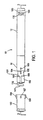
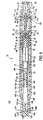
- FIG. 1 shows an auto injector, generally indicated at 10, constructed in accordance with principles of the present invention.
- the auto-injector 10 is generally comprised of a forward housing member 12 and a rearward housing member 14 connected together to define a housing with a longitudinal axis.
- a removal resistant cap 182 can be removed from the rear housing member to gain access to an actuating pin 136 that allows the user to initiate an automatic injection of an encapsulated medicament as will be described.
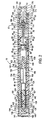
- the forward housing member 12 is an elongated, generally tubular, cylindrical plastic member that contains a dental cartridge assembly, generally indicated at 16, and a needle assembly, generally indicated at 18 and including a protective needle cover assembly 20.
- the rearward housing member 14 is an elongated, generally tubular cylindrical plastic member containing a manually operable drive assembly, generally indicated at 22.
- the rearward housing member 14 is removably fixed to the forward housing member 12 by a snap-fit connection, as will be described herein.
- the dental cartridge assembly 16 includes a medicament container in the form of a dental cartridge 24, which is tubular and made of glass.
- the dental cartridge 24 has forwardly and rearwardly facing openings at its opposite ends and is necked down at its forward end. More particularly, a major rearward portion 26 of the cartridge 24 extends rearwardly of a forward portion 28 and has an inner diameter which is larger than the inner diameter of the necked down forward portion 28.
- the dental cartridge 24 has an inwardly extending annular shoulder 30 which integrally connects the main rearward portion 26 with the smaller diameter forward portion 28.
- a forwardmost end 32 of the dental cartridge 24 has a radially extending annular flange 34 which receives a generally circular cartridge sealing member 36, preferably made of an elastic or rubber material.
- the sealing member 36 is peripherally secured to an annular outer surface 38 of the flange 34 at the forward end 32 of the cartridge 24 by means of an annular metallic clamping ring 40, thereby sealing off the forwardly facing opening at the forwardmost end 32 of the cartridge 24.
- the clamping ring 40 has a centrally disposed aperture 42 to enable the sealing member 36 to be pierced by a rearward tip portion of a needle 58 of the needle assembly 18 upon actuation of the drive assembly 22.
- the necked-down portion 28 of the cartridge 24 has a rubber washer 44 fixedly mounted thereto in surrounding relation.
- the washer 44 may be referred to as a third sealing member whose sealing function will be discussed below.
- a movable plunger 46 also preferably made of an elastic or rubber material, closes and internally seals the open rearward end 48 of the dental cartridge 24 and has a small, centrally disposed bore 50 in its rear face 52.
- the bore 50 provides a means for directly connecting to the drive assembly 22.
- the movable plunger 46 and sealing member 36 cooperate to seal a medicament 53 within the cartridge 24.
- the plunger 46 has a forwardly extending nipple type configuration 54 constructed and arranged to fit within the smaller inner diameter of the forward end of the cartridge 24 so as to substantially expel all medicament from the cartridge 24.
- the plunger 46 is slidably mounted within cartridge 24 for forward sliding movement in sealing relation with the interior surface of the cartridge 24.
- the aforementioned arrangement for the nipple type plunger 46 and the dental cartridge 24 are disclosed in the U.S. Patent Application Serial No. 08/280,884 (abandoned in favor of a continuation application, U.S. Patent Application No. 08/548,762, issued as U.S. Patent No. 5,713,866), which is incorporated by reference into the present application. It can be appreciated, however, that this arrangement is merely preferred and that the present invention contemplates that any type of plunger now known or later developed can be used.
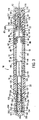
- the needle assembly 18 comprises a needle carrier 56 and a sterilized hypodermic needle 58 mounted to the carrier 56.
- the needle carrier 56 has a substantially cup-shaped or tubular cartridge mounting portion 60 having a rearwardly facing cartridge receiving opening.
- the forward end 28 of the medicament cartridge 24 extends partially into the cartridge mounting portion 60 in telescopic relation.
- An annular groove 62 is formed externally at the rear of the cup-shaped portion 60.
- the interior surface of cartridge mounting portion 60 towards the rear thereof has an annular detent groove 64.
- a peripheral edge 66 of rubber washer 44 engages the detent groove 64, preventing forward movement of the medicament cartridge 24 relative to the needle assembly 18 prior to or during the initial phase of injector activation.
- the internal surface of the cartridge mounting portion 60 of the needle assembly 18 has a series of circumferentially spaced, narrow, longitudinal slots or grooves 68 starting from the rearwardmost end of the mounting portion 60 and extending forwardly toward the rearwardly facing annular surface 67, thus traversing the detent groove 64. Because the groove 64 is of the same or greater depth relative to the depth of slots 68, the annular elastic washer 44 forms an airtight seal with groove 64.
- the slots 68 forwardly of groove 64 allow bleeding/venting of the air within space 69 of mounting portion 60 past the washer 44 in order to prevent any pressure build-up in space 69 which might hinder medicament injection or otherwise cause air to be forced into the cartridge 24 and out through the needle 58.
- the slots 68 rearwardly of groove 64 also prevent pressure build-up in space 69 during assembly.
- the disclosed medicament cartridge is movable, it is to be understood that some aspects of the present invention may be practiced without the use of movable cartridge.
- the type of cartridge wherein the forward seal bulges out to be pierced by the needle as a result of pressure applied by the drive assembly may be used.
- the needle carrier 56 has a substantially narrowed diameter tubular forward portion 70 disposed in surrounding relation to the hypodermic needle 58, thus forming a forwardly facing annular engaging surface 72 at the transition between mounting portion 60 and forward portion 70.
- the flange surface 72 is chamfered along an outer peripheral sloped edge 74 to allow for smooth forward sliding motion within the forward housing member 12.
- forward movement of needle assembly 18 causes edge 74 to eventually engage a rearwardly facing engaging surface 76 formed internally on the forward housing member 12.
- a forwardmost portion 78 of tubular portion 70 has an "O" ring groove in which an O-ring 82 is placed in sealing relation to an interior surface 100 of the protective needle cover 20.
- the O-ring 82 may be referred to as a second sealing member whose sealing function will be discussed below.
- the O-ring 82 may either seal the path hermectically or define a tortious path around it through which the air will not flow under normal conditions.
- the interior of the needle cover 90 has an annular groove 83 formed thereon.
- This groove 83 receives the O-ring 82 before the cover 90 and carrier 56 are assembled with the housing.
- the groove 83 and the O-ring 82 cooperate to keep the cover 90 locked in place.
- the cover 90 is pushed rearwardly so that the groove 83 disengages from the O-ring 82 with the O-ring being disposed in the location shown in Fig. 2.
- the hypodermic needle 58 is a substantially narrow, elongated hollow tubular steel member with forward and rearward tip portions.
- the needle 58 has a lateral slot 84 on one side thereof at the rearward tip portion 86 to allow unimpeded flow of fluid through the needle, even in the event of an obstruction at the rearward opening at rearward end 86 of the needle 58.
- the forward tip portion also has an opening to allow the medicament to flow into the injection site. The openings in the forward tip portion and the rearward tip portion are communicated by a fluid passageway.
- the type of needle shown is known as an 'anti-coring needle', an example of which is disclosed in U.S. Patent No. 5,716,348.
- the location of the openings on the needle are not critical and may be located at the very tip of each end or spaced inwardly therefrom along the tip portions.
- the rearward tip portion 86 of the needle 58 is configured to puncture the medicament cartridge sealing member 36 to establish fluid communication with medicament 53.
- the needle 58 is secured at a central exterior portion thereof to needle carrier 56 of the hub assembly 18 by means of an adhesive 88 or any other suitable means.
- the protective needle cover assembly indicated at 20 comprises a rigid plastic protective cover 90 and a forwardly disposed rubber seal 92 at the forward end of cover 90 providing a sterile barrier for the needle 58, a cover locking assembly 91, and a cover extension spring 94.
- the seal 92 may be referred to as a first sealing member whose sealing function will be discussed below.
- the protective cover 90 is substantially tubular, and has a rearward portion 96 of a slightly smaller outer diameter so as to form a rearwardly facing annular shoulder 98.
- the spring 94 has its forward volute resting on the rearwardly facing annular shoulder 98 and its rearward volute resting on the forwardly facing annular engaging surface 72 formed on the needle carrier 56 with the spring 94 slightly stressed therebetween.
- the inner surface 100 of the needle cover 90 tapers outwardly as it extends forwardly, thus enabling disengagement of O-ring 82 with surface 100 during activation and providing for unimpeded movement of the needle carrier 56 and needle 58 through needle cover 90.
- the protective cover 90 is biased by the extension spring 94 to move forwardly in surrounding protective relation over the needle 58 after actuation of the injection device 10 as will be described.
- the inner surface of the forward end of the protective needle cover 90 has an inwardly facing annular groove 102 forming an annular shoulder 104 at the forwardmost end.
- the rubber seal 92 is securely fixed into groove 102 an outwardly extending peripheral edge 106 of the seal 92 received in groove 104.
- a radially projecting annular ridge 108 is formed on the exterior of the protective cover 90 and has a rearwardly and outwardly sloping surface 110.
- Mid-positioned on the protective cover 90 is a radially inwardly and forwardly tapering surface portion 111 forwardly terminating in an annular groove, and a rearwardly facing annular shoulder 112.
- Formed on the interior surface 100 of the protective cover 90 is an inwardly extending 114 protrusion that acts as a backstop for O-ring 82.
- the forward tip portion of needle 58 and the forward portion 70 of the needle carrier 56 are telescopically received into the carrier receiving opening of the needle cover 90, with the spring 94 mounted between the needle carrier 56 and cover assembly 20.
- the O-ring 82 is pushed over the protrusion 114 and, once in position, the cover 90 and needle carrier 56 cannot be easily pulled apart. With the spring 94 slightly tensioned, the O-ring 82 backseats against the protrusion 114 and, acting in cooperation with the protective cover forward seal 92, seals the forward tip portion of the needle 58 within the cover 90.
- the entire needle 58 is sealed airtight after assembly.
- the medicament 53 can be sterilized, e.g., by steam autoclaving after assembly, without exposing the needle 58 to moisture or other elements during sterilization.
- these components are sterilized before assembly and then assembled in a sterile area.
- the sealing maintains the sterility of the needle 56 by preventing contaminated (i.e., non-sterile) air from entering the needle assembly 18 and thereby contaminating the needle 58.
- first sealing member seal 92
- second sealing member O-ring 82
- third sealing member washer 44
- the needle carrier 56 is mounted to the needle cover 90 and the cartridge 24 is mounted to the needle carrier 56 in a sterilized area, such as a sterile room.
- the needle 58 may be pre-mounted to the needle carrier 58 or may also be mounted to the needle carrier in a sterile area. After assembly these components define a needle and guide assembly which may be carried or shipped to an unsterile assembly area where the drive assembly 22 and the needle and guide assembly can be mounted within the housing.
- the use of the needle cover 90 is particularly useful in this assembly method because the cover 90 provides rigid protection for the needle 58.
- releasable spring drive assembly 22 is provided within the rearward housing portion 14 of the injector device 10.
- the drive assembly 22 includes a coil drive spring 116 and a molded plastic collet member, generally indicated at 118.
- the rearward housing member 14 is formed with an interior annular flange 120 spaced forward of the rearwardmost end thereof.
- the forward surface 122 of the annular flange 120 is adapted to be engaged by a rearward volute of the drive spring 116, which operates as a releasable energy source for the injector 10 of the present invention.
- the forward volute of the drive spring 116 engages a rearwardly facing surface 124 of a mid-positioned flange 125 of the collet member 118.
- the collet member 118 further includes a longitudinal, cylindrical shaft portion 126 that extends rearwardly from the mid-positioned flange 125 within the interior of drive spring 116.
- a rearward end portion of the cylindrical shaft portion 126 is split so as to form a plurality (two) of rearwardly extending, resilient collet arms 128 separated by a space 127.
- the rearward peripheral portion of the arms 128 are formed with radially outwardly extending flanges 130 presenting forwardly facing locking surfaces 132 which are adapted to engage along annular surface 134 of the interior annular flange 120 of the rear housing member 14.
- An actuator in the form of an actuating pin member 136 is disposed between the resilient arms 128, locking them apart in a storage or inoperative position. More specifically, pin 136 comprises a forward portion 138 that extends into the slot 127 between the resilient arms 128, preventing arms 128 from moving towards one another in FIG. 2.
- the actuating pin member 136 also has an intermediate portion 140 of a reduced diameter with respect to the forward portion 138, there being a frustoconical transition between the two portions.
- a rigid, generally cylindrical head 141 is formed at the back end of the intermediate portion 140.
- the head 141 has a generally cylindrical side wall surface 200 with an exterior diameter slightly smaller than the interior surface 202 of the rearward end portion of the rearward housing portion 14.
- the interior surface 202 of the rearward end portion defines an actuator head receiving opening and a portion of the actuator head 141 is received therein such that the exterior side wall surface 200 thereof faces the interior surface 202 in closely spaced relation.
- This closely spaced relation substantially prevents radial bending of the pin member 136 and provides a more robust actuator.
- damage to the pin member 136 can be prevented to ensure proper actuation of the drive assembly 22.
- the head 141 is solid and has two grooves 204 extending laterally thereacross. It is to be understood that the head 141 have other configurations other than cylindrical. For example, it is contemplated that the head 141 could have a square cross-section.
- the larger forward portion 138 of pin member 136 is cylindrically formed and, in the assembled position shown, engages the rearward, generally arcuate inner facing surfaces 139 of the resilient arms 128 so as to prevent the arms 128 from moving radially inwardly toward one another, thereby maintaining the locking surfaces 132 of the arms 128 in engagement with the rearward facing locking surface 134 of interior flange 120.
- the drive spring 116 is retained in stressed position between the mid-positioned flange face 124 of the collet member 118 and the forwardly facing surface 122 of the interior flange 120 of the rearward housing member 14.
- Radially inwardly extending ridges 142 extend along the inner arcuate surfaces of the collet arms 128.
- the ridges 142 act as a stop, or detent force, against any applied forward motion of the actuating pin 136 so as to prevent the accidental actuation of the injector device 10 until a sufficient amount of force is applied to clear the ridges 142.
- the forward portion 138 first rides over ridges 142, it tends to bias the arms 128 outwardly away from one another. After the majority of forward portion 138 is beyond ridges 142, the arms are forced to collapse inwardly under the force of spring 116 to release surfaces 132 from surface 134, enabling collet 118 to be thrust forward.
- An annular groove 143 is formed around the forward portion 138.
- the groove 143 receives the ridges 142 during forward movement of the pin member 136. This arrangement allows the collapsing of the collet arms to occur sooner and with less force being applied to the pin member 136 in comparison to pin members without such a groove.
- a concentric series of elongated guide ribs 144 extend forwardly from the mid-positioned flange 125 to a tapered forward flange 146 and are received into the open rearward end 48 of the medicament cartridge 24.
- a short, blunt-nosed, substantially arrow shaped portion 148 of reduced diameter extends forwardly from the tapered flange 146 and is received into the centrally located bore 50 at the rear of the plunger 46, thus directly connecting the spring drive assembly 22 to the medicament cartridge plunger 46.
- the forward end of the rearward housing member 14 is telescopically received into the rearward end of the forward housing member 12. More particularly, the forward end of the rearward housing member 14 has an annular flange 150 radially extending outwardly from an exterior surface 152 thereof.
- the exterior surface 152 is of a narrower outer diameter than that of the main body of the rearward housing member 14 so as to permit the telescopic reception.
- the forward housing member 12 has an annular groove 156 formed on the interior surface 158 toward the rearward portion thereof.
- the forward housing member 12 is secured to the rear housing member 14 by rearwardly sliding the rearward end of the forward housing member 12 in telescoping relation over the forward end of the rear housing member 14 until the annular flange 150 of the rear housing member 14 snaps into the annular groove 156 of the forward housing member 12.
- a rearward end portion 160 of the rearward housing member 14 has an outer diameter that is smaller than the main central portion 154 and sized to receive the removal resistant cover 182. As best seen in FIG. 1, the rearward end portion 160 has a forward portion 190 and a rearward portion 192, with the rearward portion 192 having a large outer diameter than forward portion 190.
- a pair of generally axially extending grooves 188 are formed through rearward portion 192 and form a continuous surface with forward portion 190.
- a generally radially extending shoulder surface 193 is defined between the forward and rearward portions 190, 192.
- the forward end of the plastic forward housing member 12 has two integrally formed opposing resilient finger snaps 168 biased radially inward into the housing member 12 through associated openings 170 of the forward housing member 12.
- the snaps 168 provide forwardly facing locking surfaces 172.
- the finger snaps 168 are disposed adjacent to and forwardly of the forwardly and radially inwardly tapered surface 111 on the exterior surface of the needle cover 90, and rearwardly of the rearwardly facing needle cover annular shoulder 112.
- the tapered surface 111 rides past finger snaps 168, forcing finger snaps 168 outwards.
- annular ridge 108 slides past the finger snap locking surfaces 172.
- Forward movement of the needle cover 90 is stopped when the sloping surface 110 of ridge 108 rides past finger snaps 168 and contacts the rear facing edges 180 formed at openings 170 as shown.
- the snap fingers 168 are disposed such that forwardly facing locking surfaces 172 thereof are behind the needle cover rearwardly facing shoulder 98.
- the finger snaps 168 and the shoulder 98 cooperate to secure the needle cover 90 in an extended, needle covering protective position (see FIG. 6) after an injection operation and preventing anyone from pushing the needle cover 90 back into the forward housing member 12 and exposing the needle 58.
- the rearward end portion 160 of the injection device 10 has a generally tubular, molded plastic cover 182 disposed in releasably locked covering relation with respect to actuating pin 136.
- the cover 182 has an annular side wall portion and a top wall portion formed integrally with the side wall portion.
- FIG. 9 which is a front end plan view of cover 182
- the forwardmost end of the cover 182 has two integrally formed, diametrically opposed, outwardly protruding cap release portions 184 on the outer surface.
- the forwardmost end of cover 182 also has two diametrically opposed, radially inwardly protruding locking projections 186 on the inner surface thereof.
- the locking projections 186 extend rearwardly from the forwardmost end of the inner surface of the cover 182 to an intermediate portion on the inner surface of the cover 182, as can be appreciated from FIGS. 7A-7C.
- the inwardly protruding locking projections 186 and the outwardly protruding cap release portions 184 are offset approximately 90 degrees from one another on the forwardmost portion of the cover 182.
- Alignment indicators 187 are embossed on the outer surface of the cover 182 at positions on the cap corresponding to the positions at which the internal locking projections 186 are disposed.
- Other alignment indicators 189 are embossed on the rear housing portion 14 at positions longitudinally aligned with the pair of axially extending grooves 188 in the enlarged diameter portion 192.
- the alignment indicators 187, 189 are in the form of arrows as shown, but may be dots or any other recessed, embossed, or labeled indication marking.
- the rearward end portion 160 is comprised of a forward portion 190 and a rearward portion 192 with a generally radially extending shoulder surface 193 extending therebetween.
- the difference in diameter is substantially equal to the height of the locking projections 186 on cap 182.
- two diametrically disposed movement limiting projections 194 are disposed on the forward portion 190.
- Projections 194 are forwardly disposed from and in general, circumferential alignment with grooves 188 as shown.
- the projections 194 are also generally circumferentially aligned with indicators 189 and protrude from the rearward end portion 160 generally to the same extent as the locking projections 186 extend inwardly from the inner surface of the cover 182.
- the movement limiting projections 194 and the projections 186 abut one another to prevent the alignment indicators 187 and 189 from being aligned with one another upon simple turning of the cover 182.
- locking projections 186 cannot be aligned with grooves 188 on the injector body and the cover 182 cannot be removed from covering relation with respect to actuating pin member 136.
- This position may be considered to be a removal resisting position.
- the indicators 187 and 189 In order to remove the cover 182, the indicators 187 and 189 must be aligned, so that the locking projections 186 of cover 182 can be generally circumferentially aligned with grooves 188 and pulled axially rearwardly therethrough.
- the cover 182 may be considered to be in a removal allowing position when the locking projections 186 are aligned with the grooves 188.
- the cap release portions 184 In order to align indicators 187 and 189, the cap release portions 184 must be manually squeezed.
- the plastic material forming cover 182 is sufficiently yieldingly deformable such that squeezing the portions 184 will distort the cross sectional shape of the cap 182 into a generally oval configuration, thus moving locking projections 186 generally radially outwardly away from one another from a normal, locking position to a releasing position.
- the cover 182 can be rotated so that projections 186 are disposed in overlapping alignment with movement limiting projections 194, as can be appreciated from FIG. 7B.
- the indicators 187 and 189 are now aligned, and the cover 182 can be pulled off the injection body, with locking projections 186 passing through grooves 188.
- the locking projections 186, the grooves 188, the movement limiting projections 194, and the shoulder surface 193 may be reversed so that the structure defining the groove 188 and the shoulder surface 193 is located on the interior of the cap 182 and the locking projections 186 are located on the housing 12.
- the construction shown in the Figures is preferred because it is easier to manufacture.
- the user grasps the body of the injector device 10 and places the forwardmost end portion 176 against the portion of flesh to be injected.
- the actuating pin member 136 is then urged forwardly by a thumb or finger with enough force to overcome the engagement of the forward portion 138 with the ridges 142.
- the intermediate narrower portion 140 of actuating pin 136 then moves into the slotted area 127, closer to locking surface 132 and 134.
- the rearward end of the collet arms 128 are thus permitted to deflect inwardly towards the narrower portion 140 to an extent sufficient that the locking surfaces 132 slidingly disengage from the interior annular flange locking surfaces 134 under the force of spring 116.
- the collet member 118 then moves forwardly by the action of the drive spring 116, initially pulling the pin 136 forward within slot 127. As the collet member 118 continues to move forwardly, the actuating pin member 136 is left behind in captured relation within the cup-shaped end 164 of rear housing member 14 thereby preventing the actuating pin 136 from becoming a loose part.
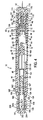
- the collet member 118 is driven forwardly against the rear end 52 of the slidable plunger 46. This, in turn, urges both the medicament cartridge 24 and needle carrier 56 forwardly until the peripheral sloped edge 74 of needle carrier 56 engages the engaging surface 76 on the interior surface of forward housing 12, preventing any further forward movement of the needle carrier 56. At this point, the needle 58 is in the injecting position. During this movement, the plunger 46 does not move relative to cartridge 24 due to incompressibility of medicament 53. Also, cartridge 24 does not move relative to needle carrier 56 as a result of the interengagement between the washer 44 and the groove 64.
- the forward movement of the needle carrier 56 compresses the extension spring 94 against the rearwardly facing shoulder 98 of the needle cover 90. Also, the movement of the needle assembly 18 causes the front end of the needle 58 to puncture the rubber seal 92 at the forwardmost end 176 of the injector device 10 and be pushed into the injection site.
- fluid medicament 53 begins to flow through the needle. More specifically, the drive spring 116 pushes the plunger 46 forwardly within medicament cartridge 24, thereby forcing the fluid medicament 53 outwardly from the cartridge 24 and through the needle 58 into the injection site. The plunger 46 slidingly moves to the forwardmost position within the medicament cartridge 24 to substantially expel all of the fluid medicament 53 therein. It can be appreciated, however, that the distance between the front end of the collet 188 and the flange may have a shorter length such that the plunger does not move all the way forward inside the cartridge 24. This arrangement is preferred when it is desired to expel only a portion of the medicament 53 from the cartridge 24.
- Epinephrine it is desirable to have a cartridge with a 1 ml supply and the collet is configured to cause only .3 ml to be injected into the injection site.
- expensive medicaments however, it is more cost-effective to expel as much medicament as possible to avoid waste.
- the needle cover 90 is moved forwardly by the extension spring 94 into the protective position. More specifically, the needle cover extension spring 94 is compressed upon actuation of the injector device 10. The return spring 94 biases the needle cover 90 for forward movement, overcoming the finger snaps 168 retaining it within forward housing 12. However, while the user holds the injector device 10 against the injection site, the needle cover 90 remains in place.
- the extension spring 94 drives the needle cover 90 forwardly.
- the needle cover ridge 108 then slides past finger snaps 168, whereupon the locking surfaces 172 snap inwardly behind shoulder 98 so as to secure the needle cover 90 in the forwardly extending protective position.
- the needle cover 90 now projects forwardly beyond the forwardmost end 176 of the injector device 10, covering the forward portion of the needle 58 for disposal of the device.
- the auto-injector device 10 incorporates a needle cover assembly 20 that replaces the traditional needle sheath and provides rigid protection for the needle 58.
- the rigid needle cover 90 encapsulates the forward end of the needle after an injection and prevents the user from seeing the needle 58 as it is withdrawn from the injection site.
- the needle cover 90 also locks in the extended protective position thereby preventing undesirable access to the needle 58 after an injection operation.
- the activation pin 136 snap-fit interference with the resilient collet arms 128 provides for a controlled activation load which must be applied in order to actuate the auto-injection device 10.
- the needle 58 is sealed within the device 10 prior to use, to allow for post-assembly sterilization of medicament by means of autoclaving with a pressurized steam/air mixture. More specifically, the rubber washer 44, O-ring 82, and needle cover forward seal 92 isolate the needle 58 preventing moisture ingress into the needle area during sterilization. A secondary function of the rubber washer 44 is to provide a detent snap to keep the medicament cartridge 24 back prior to activation of the device, and to prevent the rear end 86 of the needle 58 separated from the forward cartridge seal 36 prior to activation of the device.
Claims (13)
- Automatische Injektionsvorrichtung (10), die aufweist:wobei die Nadel (58) relativ zu dem Gehäuse zwischen (i) einer normalen, inoperativen Position, in welcher die Nadel (58) vollständig in dem Gehäuse angeordnet ist, und (ii) einer Injektionsstellung bewegbar ist, in welcher der vordere Spitzenabschnitt der Nadel (58) sich von dem vorderen Endabschnitt (176) des Gehäuses nach vorn erstreckt;ein Gehäuse mit einer Längsachse und gegenüberliegenden vorderen (176) und hinteren (160) Endabschnitten, wobei der vordere Endabschnitt (176) mit einem eine Injektionsstelle definierenden Abschnitt von Fleisch in Eingriff gebracht werden kann;eine Nadel (58) mit einem vorderen Spitzenabschnitt, einem hinteren Spitzenabschnitt (86) und einem Fluiddurchgang, der darin gebildet und zu dem vorderen und hinteren Spitzenabschnitt offen ist;
eine Arzneimittelpatrone (24) mit einem abgedichteten Inneren, das einen Vorrat eines fließfähigen Arzneimittels enthält;
wobei die Arzneimittelpatrone (24) normalerweise gegenüber der Nadel (58) abgedichtet ist, wobei die Arzneimittelpatrone (24) und die Nadel (58) so konstruiert und angeordnet sind, dass sie während eines automatischen Injektionsvorgangs in Fluidverbindung stehen, so dass der hintere Spitzenabschnitt der Nadel (58) die Patrone (24) durchsticht und sich nach hinten in das Patroneninnere erstreckt, so dass der Fluiddurchgang der Nadel (58) in Fluidverbindung mit dem Patroneninneren steht und das fließfähige, in dem Patroneninneren enthaltene Arzneimittel in den Fluiddurchgang fließen kann; und
eine manuell betreibbare Antriebsanordnung (22) mit einem Betätigungselement (136), das sich generell nach hinten von dem hinteren Endabschnitt (160) des Gehäuses erstreckt, wobei die Antriebsanordnung (22) so konstruiert und angeordnet ist, dass ein Benutzer den automatischen Injektionsvorgang ausführen kann, indem er den vorderen Endabschnitt (176) des Gehäuses mit der obengenannten Injektionsstelle in Eingriff bringt und das Betätigungselement manuell betreibt, so dass die Antriebsanordnung die Nadel (58) in ihre Injektionsstellung bewegt und bewirkt, dass die Patrone (24) und die Nadel (58) in Fluidverbindung kommen, so dass der vordere Spitzenabschnitt der Nadel (58) die Injektionsstelle durchsticht und der hintere Spitzenabschnitt (86) der Nadel (58) die Patrone durchsticht, wobei die Antriebsanordnung danach das fließfähige Arzneimittel von dem Patroneninneren durch den Fluiddurchgang der Nadel (58) nach außen und in die Injektionsstelle treibt; dadurch gekennzeichnet, dass sie weiterhin aufweist:wobei die Abdeckung (182) für das Betätigungselement oder der hintere Endabschnitt (160) des Gehäuses einen sich generell radial erstreckenden Verriegelungsvorsprung (186) bereitstellen und das entsprechende andere von Abdeckung (182) für das Betätigungselement und hinterem Endabschnitt (160) des Gehäuses eine Struktur hat, die eine sich generell radial erstreckende Absatzfläche (193) und eine sich generell axial erstreckende Nut (188), die zur Absatzfläche hin offen ist, definiert;eine dem Entfernen widerstrebende Abdeckung (182) für das Betätigungselement, die an dem hinteren Endabschnitt (160) des Gehäuses so angeordnet ist, dass sie das Betätigungselement (136) abdeckt und einen unbeabsichtigten Betrieb des Betätigungselements verhindert, wobei die Abdeckung einen ringförmigen Wandabschnitt hat, der aus einem nachgiebig verformbaren Material gefertigt ist;
wobei die Abdeckung (182) und der hintere Endabschnitt (160) des Gehäuses so konstruiert und angeordnet sind, dass die Abdeckung (182) relativ zu dem hinteren Endabschnitt (160) des Gehäuses um die obengenannte Längsachse gedreht werden kann von (i) einer einem Entfernen widerstrebenden Position, in welcher der Verriegelungsvorsprung (186) und die Nut (188) in Umfangsrichtung nicht in Bezug zueinander ausgerichtet sind, so dass die Absatzfläche (193) und der Vorsprung zusammenwirken, um zu verhindern, dass die Abdeckung (182) axial nach außen relativ zu dem hinteren Abschnitt (160) des Gehäuses bewegt wird, und (ii) einer ein Entfernen erlaubenden Position, in welcher der Verriegelungsvorsprung (186) und die Nut (188) im Wesentlichen in Umfangsrichtung in Bezug zueinander ausgerichtet sind, so dass die Abdeckung (182) von dem hinteren Abschnitt (160) des Gehäuses durch Bewegen der Abdeckung (182) axial nach außen relativ zu dem hinteren Abschnitt (160) des Gehäuses entfernt werden kann, um das Betätigungselement freizulegen und einen manuellen Betrieb desselben zu ermöglichen;
wobei die Abdeckung (182) oder der hintere Endabschnitt (160) des Gehäuses einen die Bewegung einschränkenden Vorsprung (194) hat, der im Wesentlichen in Umfangsrichtung mit der Nut (188) ausgerichtet ist;
wobei die Abdeckung (182) für das Betätigungselement so konstruiert und angeordnet ist, dass der Benutzer den ringförmigen Wandabschnitt durch Ausüben eines Druckes mit der Hand manuell verformen kann, um eine generell radiale relative Bewegung zwischen dem Verriegelungsvorsprung (186) und dem eine Bewegung einschränkenden Vorsprung (194) von normalen Verriegelungspositionen in Freigabepositionen zu bewirken;
wobei der eine Bewegung einschränkende Vorsprung (194) so positioniert und konfiguriert ist, dass, wenn der Verriegelungsvorsprung (186) und der eine Bewegung einschränkende Vorsprung (194) in ihren Verriegelungspositionen sind, der Verriegelungsvorsprung (186) in Eingriff mit dem eine Bewegung einschränkenden Vorsprung (194) ist, wenn die Abdeckung (182) in Richtung ihrer ein Entfernen erlaubenden Position gedreht wird, um hierdurch zu verhindern, dass die Abdeckung (182) in die ein Entfernen erlaubende Position gedreht wird;
wobei der eine Bewegung einschränkende Vorsprung (194) so positioniert und konfiguriert ist, dass, wenn der Verriegelungsvorsprung (186) und der eine Bewegung einschränkende Vorsprung (194) in ihren Freigabepositionen sind, der Verriegelungsvorsprung (186) über den eine Bewegung einschränkenden Vorsprung (194) hinweg gelangt, wenn die Abdeckung (182) in Richtung ihrer ein Entfernen erlaubenden Position gedreht wird, um dadurch zu gestatten, dass die Abdeckung (182) in die ein Entfernen erlaubende Position gedreht werden kann. - Automatische Injektionsvorrichtung (10) nach Anspruch 1, wobei der Verriegelungsvorsprung (186) an einer Innenfläche der Abdeckung (182) für das Betätigungselement vorgesehen ist und wobei der eine Bewegung einschränkende Vorsprung (194) und die Struktur, die die Absatzfläche (193) und die Nut (188) definiert, an dem hinteren Endabschnitt (160) des Gehäuses vorgesehen ist.
- Automatische Injektionsvorrichtung (10) nach Anspruch 2, wobei die Abdeckung (182) für das Betätigungselement weiterhin einen oberen Wandabschnitt aufweist, der integral mit dem Seitenwandabschnitt gebildet ist.
- Automatische Injektionsvorrichtung (10) nach Anspruch 3, wobei die Abdeckung (182) ein Paar der Verriegelungsvorsprünge (186) hat, die ungefähr um 180° voneinander entfernt angeordnet sind und wobei der hintere Endabschnitt (160) des Gehäuses ein Paar Nuten (188) hat, die ungefähr um 180° voneinander entfernt angeordnet sind und ein Paar die Bewegung einschränkender Vorsprünge (194), die ungefähr um 180° voneinander entfernt angeordnet sind.
- Automatische Injektionsvorrichtung (10) nach Anspruch 2, wobei der hintere Endabschnitt (160) des Gehäuses eine dem Gehäuse zugeordnete Anzeigemarkierung (189) hat, die an einer Außenfläche desselben gebildet ist und die Abdeckung (182) für das Betätigungselement eine der Abdeckung zugeordnete Anzeigemarkierung (187) hat, die an einer Außenfläche desselben gebildet ist, wobei die Anzeigemarkierungen so positioniert sind, dass sie generell in Umfangsrichtung miteinander ausgerichtet sind, wenn die Abdeckung (182) für das Betätigungselement in ihrer ein Entfernen erlaubenden Position ist, wodurch dem Benutzer angezeigt wird, dass die Abdeckung (182) in die ein Entfernen erlaubende Position gedreht wurde.
- Automatische Injektionsvorrichtung (10) nach Anspruch 5, wobei jede der Anzeigemarkierungen (187, 189) ein Pfeil ist.
- Automatische Injektionsvorrichtung (10) nach Anspruch 2, die weiterhin eine Nadelbaugruppe (18) aufweist, die die Nadel (58) und einen Nadelträger (56) aufweist, der relativ zu dem Gehäuse bewegbar ist, wobei die Nadel (58) fest an dem Nadelträger (56) montiert ist,
wobei die Nadelbaugruppe (18) weiterhin eine im Wesentlichen starre, rohrförmige Nadelschutzabdeckung (90) und eine Zugfeder für die Abdeckung (94) aufweist, die zwischen der Nadelabdeckung (90) und dem Nadelträger (56) angeordnet ist, wobei die Nadelabdeckung (90) eine im Wesentlichen starre rohrförmige Wand hat, die eine nach vorne weisende Nadel-Durchgangsöffnung definiert;
wobei die Nadelbaugruppe (18) so konstruiert und ausgebildet ist, dass, nachdem die Antriebsanordnung (22) bewirkt hat, dass die Patrone (24) und die Nadel (58) in Fluidverbindung stehen und die Nadel (58) in ihre Injektionsstellung bewegt hat, die Zugfeder für die Abdeckung (94) sich flexibel ausdehnt als Folge davon, dass der vordere Endabschnitt (176) des Gehäuses von der Injektionsstelle gelöst wird, um die Nadelschutzabdeckung (90) nach vorne von einer inoperativen, zurückgezogenen Position in eine ausgezogene die Nadel schützende Position zu bewegen, wobei die Nadel-Durchgangsöffnung vor dem vorderen Spitzenabschnitt der Nadel angeordnet ist, wobei die starre rohrförmige Wand die Nadel schützend umgibt. - Automatische Injektionsvorrichtung (10) nach Anspruch 7, wobei der Nadelträger (56) einen rohrförmigen Patronen-Befestigungsabschnitt (60) hat, der eine nach hinten weisende, die Patrone aufnehmende Öffnung definiert, wobei der Patronen-Befestigungsabschnitt (60) eine Innenfläche hat, die eine ringförmige Nut (64) definiert;
wobei die Patrone (24) ein ringförmiges Dichtungselement (44) hat, das fest daran befestigt ist und in Bezug auf den Nadelträger (56) gleitend bewegbar ist zwischen (i) einer normalen inoperativen Position, in welcher die Patrone (24) nicht durchstochen ist und hinter dem hinteren Spitzenabschnitt der Nadel (58) angeordnet ist und (ii) einer Arzneimittel-Zufuhrposition, in welcher die Nadel (58) und die Patrone (24) in Fluidverbindung stehen;
wobei die Patrone (24) in der Patronen-Aufnahmeöffnung aufgenommen ist, wobei deren Dichtungselement (44) entfernbar in der ringförmigen Nut (64) so aufgenommen ist, dass das Dichtungselement (44) und die ringförmige Nut (64) zusammenwirken, um (i) im Wesentlichen die nach hinten weisende Öffnung des Patronen-Befestigungsabschnitts (60) abzudichten und (ii) zu verhindern, dass die Patrone (24) sich nach vorne relativ zur Nadel (58) in Richtung ihrer Arzneimittel-Zufuhrposition bewegt, bevor die Antriebsanordnung (22) betätigt wird. - Automatische Injektionsvorrichtung (10) nach Anspruch 8, wobei die Innenfläche des Patronen-Befestigungsabschnitts (60) des Nadelträgers (56) eine Mehrzahl von daran geformten, sich generell axial erstreckenden Nuten (68) hat,
wobei die sich generell axial erstreckenden Nuten (68) so positioniert und konfiguriert sind, dass Luft aus dem Inneren des Patronen-Befestigungsabschnitts (60) um das Dichtungselement (44) herum entweichen kann, wenn die Patrone nach vorne in ihre Arzneimittel-Zufuhrposition bewegt wird, um dadurch einen Druckaufbau in dem Träger zu verhindern. - Automatische Injektionsvorrichtung (10) nach Anspruch 9, wobei der Patronen-Befestigungsabschnitt (60) des Nadelträgers (56) eine nach hinten weisende Eingriffsfläche (67) hat und wobei die Patrone (24) einen Kolben (46) hat, der gleitend beweglich in deren Innerem angebracht ist;
wobei die nach hinten weisende Eingriffsfläche (67) so positioniert und konfiguriert ist, dass eine nach vorne weisende Eingriffsfläche (32) der Patrone (24) in Eingriff mit der nach hinten weisenden Eingriffsfläche (62) kommt, wenn die Patrone nach vorne in ihre Arzneimittel-Zufuhrposition bewegt wird, um eine weitere relative Bewegung nach vorne der Patrone (24) in Bezug auf den Nadelträger (56) zu verhindern,
wobei die Antriebsanordnung (22) so konstruiert und ausgebildet ist, dass sie den Kolben (44) nach vorne in Bezug auf die Patrone (24) bewegt, nachdem die Patrone (24) in ihre Arzneimittel-Zufuhrposition bewegt wurde, um das fließfähige Arzneimittel aus dem Patroneninneren herauszutreiben. - Automatische Injektionsvorrichtung (10) nach Anspruch 10, wobei der Nadelträger (56) eine nach vorne weisende Eingriffsfläche (72) hat und die Nadelschutzabdeckung (90) eine nach hinten weisende Eingriffsfläche (98) hat,
wobei die Nadelbaugruppe (18) und die Patrone (24) so konstruiert und ausgebildet sind, dass während des automatischen Injektionsvorgangs die Antriebsanordnung (22) (i) den Nadelträger (56) und die Patrone (24) zusammen nach vorn relativ zu der Nadelschutzabdeckung (90) antreibt, bis die Nadel (58) in ihre Injektionsstellung bewegt wird und die nach vorne weisende Eingriffsfläche (72) des Nadelträgers (56) mit der nach hinten weisenden Eingriffsfläche (98) der Nadelabdeckung (90) in Eingriff kommt, um eine weitere relative Vorwärtsbewegung des Nadelträgers (56) in Bezug auf die Nadelabdeckung (90) zu beschränken, (ii) dann die Patrone (24) nach vorne in ihre Arzneimittel-Zufuhrposition bewegt, bis die nach vorne weisende Eingriffsfläche (32) der Patrone (24) in Eingriff mit der nach hinten weisenden Eingriffsfläche (67) des Nadelträgers (56) kommt, um eine weitere relative Vorwärtsbewegung der Patrone (24) in Bezug auf den Nadelträger (56) zu verhindern und (iii) den Kolben nach vorne in Bezug zu der Patrone bewegt, um das Arzneimittel aus dem Patroneninneren durch den Fluiddurchgang der Nadel (58) nach außen zu treiben. - Automatische Injektionsvorrichtung (10) nach Anspruch 1, wobei die Patrone (24) eine nach vorne weisende Öffnung und ein Patronen-Abdichtungselement (36), das durchstochen werden kann und die nach vorne weisende Öffnung abdichtet, hat, wobei die Patrone (24) gleitend zwischen (i) einer normalen inoperativen Position, in welcher die Patrone nicht durchstochen ist und hinter dem hinteren Spitzenabschnitt (86) der Nadel (58) angeordnet ist und (ii) einer Arzneimittel-Zufuhrposition, in welcher die Nadel (58) und die Patrone (24) in Fluidverbindung stehen, bewegbar ist.
- Automatische Injektionsvorrichtung (10) nach Anspruch 2, wobei der hintere Endabschnitt (160) des Gehäuses einen ringförmigen Flansch und einen sich nach hinten erstreckenden Flansch (120) aufweist, wobei die Antriebsanordnung (22) aufweist:wobei der sich nach innen erstreckende Flansch (120) eine nach hinten weisende Verriegelungsfläche (134) bereitstellt und die flexiblen Arme (128) Endabschnitte haben, . die nach vorne weisende Verriegelungsflächen (132) bereitstellen, wobei die Verriegelungsflächen in Eingriff sind um zu verhindern, dass die Klemmzange (118) sich in Bezug auf das Gehäuse nach vorne bewegt;eine Klemmzange (118) mit einem Paar flexibler Arme (128) und einem ringförmigen, sich nach außen erstreckenden Flansch (125), wobei die Klemmzange (118) einen vorderen Endabschnitt hat, der in Eingriff mit der Patrone (24) ist;eine komprimierte Schraubenfeder (116), die mit dem sich nach innen erstreckenden Flansch (120) und dem sich nach außen erstreckenden Flansch (125) in Eingriff ist;
wobei das Betätigungselement (136) einen vorderen Abschnitt (138) hat, der zwischen den flexiblen Armen (128) so aufgenommen ist, dass verhindert wird, dass die Endabschnitte der Arme sich aufeinander zu bewegen, und einen Zwischenabschnitt (140), welcher dünner als der vordere Abschnitt (138) ist;
wobei das Betätigungselement (136) so konstruiert und angeordnet ist, dass ein manuelles Bewegen des Betätigungselements (136) nach vorne ermöglicht, dass die Endabschnitte der flexiblen Arme (128) nach innen in Richtung des dünneren Zwischenabschnitts zusammenfallen, so dass die Verriegelungsflächen (132, 134) außer Eingriff kommen und ermöglichen, dass sich die Feder (116) ausdehnt und die Klemmzange (118) nach vorne antreibt.
Applications Claiming Priority (3)
| Application Number | Priority Date | Filing Date | Title |
|---|---|---|---|
| US6977597P | 1997-12-16 | 1997-12-16 | |
| US69775P | 1997-12-16 | ||
| PCT/US1998/026666 WO1999030759A2 (en) | 1997-12-16 | 1998-12-16 | Automatic injector for administrating a medicament |
Publications (2)
| Publication Number | Publication Date |
|---|---|
| EP1039942A2 EP1039942A2 (de) | 2000-10-04 |
| EP1039942B1 true EP1039942B1 (de) | 2004-10-13 |
Family
ID=22091145
Family Applications (1)
| Application Number | Title | Priority Date | Filing Date |
|---|---|---|---|
| EP98963219A Expired - Lifetime EP1039942B1 (de) | 1997-12-16 | 1998-12-16 | Automatische injektionsvorrichtung zur verabreichung eines medikamentes |
Country Status (9)
| Country | Link |
|---|---|
| US (1) | US6210369B1 (de) |
| EP (1) | EP1039942B1 (de) |
| JP (1) | JP2002508225A (de) |
| AU (1) | AU738058B2 (de) |
| CA (1) | CA2315146C (de) |
| DE (1) | DE69827036T2 (de) |
| IL (2) | IL136714A0 (de) |
| WO (1) | WO1999030759A2 (de) |
| ZA (1) | ZA9811594B (de) |
Families Citing this family (233)
| Publication number | Priority date | Publication date | Assignee | Title |
|---|---|---|---|---|
| FR2774294B1 (fr) * | 1998-02-04 | 2000-04-14 | Marc Brunel | Dispositif d'injection automatique d'une dose de produit medicamenteux |
| US6391005B1 (en) | 1998-03-30 | 2002-05-21 | Agilent Technologies, Inc. | Apparatus and method for penetration with shaft having a sensor for sensing penetration depth |
| CA2632856C (en) | 1998-06-24 | 2010-10-12 | Chen & Chen, Llc | Fluid sample testing system |
| US6780617B2 (en) | 2000-12-29 | 2004-08-24 | Chen & Chen, Llc | Sample processing device and method |
| US7799521B2 (en) * | 1998-06-24 | 2010-09-21 | Chen & Chen, Llc | Thermal cycling |
| US6364865B1 (en) * | 1998-11-13 | 2002-04-02 | Elan Pharma International Limited | Drug delivery systems and methods |
| US20020193740A1 (en) | 1999-10-14 | 2002-12-19 | Alchas Paul G. | Method of intradermally injecting substances |
| US7241275B2 (en) * | 1999-10-14 | 2007-07-10 | Becton, Dickinson And Company | Intradermal needle |
| US6494865B1 (en) * | 1999-10-14 | 2002-12-17 | Becton Dickinson And Company | Intradermal delivery device including a needle assembly |
| US6843781B2 (en) | 1999-10-14 | 2005-01-18 | Becton, Dickinson And Company | Intradermal needle |
| US6569123B2 (en) | 1999-10-14 | 2003-05-27 | Becton, Dickinson And Company | Prefillable intradermal injector |
| US6569143B2 (en) | 1999-10-14 | 2003-05-27 | Becton, Dickinson And Company | Method of intradermally injecting substances |
| US6776776B2 (en) * | 1999-10-14 | 2004-08-17 | Becton, Dickinson And Company | Prefillable intradermal delivery device |
| US6607508B2 (en) | 2000-04-27 | 2003-08-19 | Invivotech, Inc. | Vial injector device |
| WO2002032287A2 (en) | 2000-10-17 | 2002-04-25 | Schneider Patricia G | Emergency medical dispensing card |
| US8641644B2 (en) | 2000-11-21 | 2014-02-04 | Sanofi-Aventis Deutschland Gmbh | Blood testing apparatus having a rotatable cartridge with multiple lancing elements and testing means |
| SE518981C2 (sv) * | 2000-12-14 | 2002-12-17 | Shl Medical Ab | Autoinjektor |
| DE10106367B4 (de) * | 2001-02-12 | 2009-11-19 | Tecpharma Licensing Ag | Ablesehilfe für eine Vorrichtung zur Verabreichung einer einstellbaren Dosis eines injizierbaren Produkts |
| DE60130582T2 (de) * | 2001-04-13 | 2008-06-12 | Becton Dickinson And Co. | Vorgefüllte intradermalverabreichungsvorrichtung |
| WO2002083215A1 (en) * | 2001-04-13 | 2002-10-24 | Becton Dickinson And Company | Intradermal needle |
| US9795747B2 (en) | 2010-06-02 | 2017-10-24 | Sanofi-Aventis Deutschland Gmbh | Methods and apparatus for lancet actuation |
| US9427532B2 (en) | 2001-06-12 | 2016-08-30 | Sanofi-Aventis Deutschland Gmbh | Tissue penetration device |
| ES2336081T3 (es) | 2001-06-12 | 2010-04-08 | Pelikan Technologies Inc. | Dispositivo de puncion de auto-optimizacion con medios de adaptacion a variaciones temporales en las propiedades cutaneas. |
| US7025774B2 (en) | 2001-06-12 | 2006-04-11 | Pelikan Technologies, Inc. | Tissue penetration device |
| AU2002348683A1 (en) | 2001-06-12 | 2002-12-23 | Pelikan Technologies, Inc. | Method and apparatus for lancet launching device integrated onto a blood-sampling cartridge |
| US8337419B2 (en) | 2002-04-19 | 2012-12-25 | Sanofi-Aventis Deutschland Gmbh | Tissue penetration device |
| US9226699B2 (en) | 2002-04-19 | 2016-01-05 | Sanofi-Aventis Deutschland Gmbh | Body fluid sampling module with a continuous compression tissue interface surface |
| JP4149911B2 (ja) | 2001-06-12 | 2008-09-17 | ペリカン テクノロジーズ インコーポレイテッド | 電気式ランセットアクチュエータ |
| US7981056B2 (en) | 2002-04-19 | 2011-07-19 | Pelikan Technologies, Inc. | Methods and apparatus for lancet actuation |
| EP1416986A4 (de) * | 2001-06-29 | 2005-12-14 | Becton Dickinson Co | Intradermale freisetzung von vakzinen und gentherapeutischen mitteln mit einer mikrokanüle |
| US20060018877A1 (en) * | 2001-06-29 | 2006-01-26 | Mikszta John A | Intradermal delivery of vacccines and therapeutic agents |
| US7544188B2 (en) * | 2001-07-19 | 2009-06-09 | Intelliject, Inc. | Medical injector |
| JP4513085B2 (ja) * | 2001-09-11 | 2010-07-28 | アイキューム インク | 試料の容器 |
| US6808511B2 (en) * | 2001-10-11 | 2004-10-26 | Gary J. Pond | Disposable aspirating safety syringe |
| WO2003039632A2 (en) * | 2001-11-02 | 2003-05-15 | Meridian Medical Technologies, Inc. | A medicament container, a medicament dispensing kit for administering medication and a method for packaging the same |
| CA2475573C (en) | 2002-02-11 | 2013-03-26 | Antares Pharma, Inc. | Intradermal injector |
| US8267870B2 (en) | 2002-04-19 | 2012-09-18 | Sanofi-Aventis Deutschland Gmbh | Method and apparatus for body fluid sampling with hybrid actuation |
| US9314194B2 (en) | 2002-04-19 | 2016-04-19 | Sanofi-Aventis Deutschland Gmbh | Tissue penetration device |
| US7491178B2 (en) | 2002-04-19 | 2009-02-17 | Pelikan Technologies, Inc. | Method and apparatus for penetrating tissue |
| US7229458B2 (en) | 2002-04-19 | 2007-06-12 | Pelikan Technologies, Inc. | Method and apparatus for penetrating tissue |
| US9795334B2 (en) | 2002-04-19 | 2017-10-24 | Sanofi-Aventis Deutschland Gmbh | Method and apparatus for penetrating tissue |
| US7901362B2 (en) | 2002-04-19 | 2011-03-08 | Pelikan Technologies, Inc. | Method and apparatus for penetrating tissue |
| US7892183B2 (en) | 2002-04-19 | 2011-02-22 | Pelikan Technologies, Inc. | Method and apparatus for body fluid sampling and analyte sensing |
| US7331931B2 (en) | 2002-04-19 | 2008-02-19 | Pelikan Technologies, Inc. | Method and apparatus for penetrating tissue |
| US8702624B2 (en) | 2006-09-29 | 2014-04-22 | Sanofi-Aventis Deutschland Gmbh | Analyte measurement device with a single shot actuator |
| US9248267B2 (en) | 2002-04-19 | 2016-02-02 | Sanofi-Aventis Deustchland Gmbh | Tissue penetration device |
| US7547287B2 (en) | 2002-04-19 | 2009-06-16 | Pelikan Technologies, Inc. | Method and apparatus for penetrating tissue |
| US8221334B2 (en) | 2002-04-19 | 2012-07-17 | Sanofi-Aventis Deutschland Gmbh | Method and apparatus for penetrating tissue |
| US7297122B2 (en) | 2002-04-19 | 2007-11-20 | Pelikan Technologies, Inc. | Method and apparatus for penetrating tissue |
| US7674232B2 (en) | 2002-04-19 | 2010-03-09 | Pelikan Technologies, Inc. | Method and apparatus for penetrating tissue |
| US7648468B2 (en) * | 2002-04-19 | 2010-01-19 | Pelikon Technologies, Inc. | Method and apparatus for penetrating tissue |
| US7976476B2 (en) | 2002-04-19 | 2011-07-12 | Pelikan Technologies, Inc. | Device and method for variable speed lancet |
| US8360992B2 (en) | 2002-04-19 | 2013-01-29 | Sanofi-Aventis Deutschland Gmbh | Method and apparatus for penetrating tissue |
| US8372016B2 (en) | 2002-04-19 | 2013-02-12 | Sanofi-Aventis Deutschland Gmbh | Method and apparatus for body fluid sampling and analyte sensing |
| US8784335B2 (en) | 2002-04-19 | 2014-07-22 | Sanofi-Aventis Deutschland Gmbh | Body fluid sampling device with a capacitive sensor |
| US7198606B2 (en) | 2002-04-19 | 2007-04-03 | Pelikan Technologies, Inc. | Method and apparatus for a multi-use body fluid sampling device with analyte sensing |
| US7909778B2 (en) | 2002-04-19 | 2011-03-22 | Pelikan Technologies, Inc. | Method and apparatus for penetrating tissue |
| US7175642B2 (en) | 2002-04-19 | 2007-02-13 | Pelikan Technologies, Inc. | Methods and apparatus for lancet actuation |
| US7232451B2 (en) * | 2002-04-19 | 2007-06-19 | Pelikan Technologies, Inc. | Method and apparatus for penetrating tissue |
| US8579831B2 (en) | 2002-04-19 | 2013-11-12 | Sanofi-Aventis Deutschland Gmbh | Method and apparatus for penetrating tissue |
| US6979316B1 (en) * | 2002-05-23 | 2005-12-27 | Seedlings Life Science Ventures Llc | Apparatus and method for rapid auto-injection of medication |
| US6896666B2 (en) * | 2002-11-08 | 2005-05-24 | Kochamba Family Trust | Cutaneous injection delivery under suction |
| US20060264926A1 (en) * | 2002-11-08 | 2006-11-23 | Kochamba Gary S | Cutaneous stabilization by vacuum for delivery of micro-needle array |
| US8574895B2 (en) | 2002-12-30 | 2013-11-05 | Sanofi-Aventis Deutschland Gmbh | Method and apparatus using optical techniques to measure analyte levels |
| US7252651B2 (en) * | 2003-01-07 | 2007-08-07 | Becton, Dickinson And Company | Disposable injection device |
| EP1596910B1 (de) | 2003-01-30 | 2016-10-19 | Becton Dickinson and Company | Intradermale abgabevorrichtung mit konturierter hauteingriffs-oberflächengeometrie |
| WO2004080597A2 (en) | 2003-02-05 | 2004-09-23 | Iquum, Inc. | Sample processing tubule |
| EP1628567B1 (de) | 2003-05-30 | 2010-08-04 | Pelikan Technologies Inc. | Verfahren und vorrichtung zur injektion von flüssigkeit |
| US7850621B2 (en) | 2003-06-06 | 2010-12-14 | Pelikan Technologies, Inc. | Method and apparatus for body fluid sampling and analyte sensing |
| WO2006001797A1 (en) | 2004-06-14 | 2006-01-05 | Pelikan Technologies, Inc. | Low pain penetrating |
| US20050027255A1 (en) * | 2003-07-31 | 2005-02-03 | Sid Technologies, Llc | Automatic injector |
| IL157981A (en) | 2003-09-17 | 2014-01-30 | Elcam Medical Agricultural Cooperative Ass Ltd | Auto injector |
| EP1671096A4 (de) | 2003-09-29 | 2009-09-16 | Pelikan Technologies Inc | Verfahren und apparatur für eine verbesserte probeneinfangvorrichtung |
| EP1680014A4 (de) | 2003-10-14 | 2009-01-21 | Pelikan Technologies Inc | Verfahren und gerät für eine variable anwenderschnittstelle |
| US7635348B2 (en) * | 2003-11-04 | 2009-12-22 | Meridian Medical Technologies, Inc. | Container for medicament automatic injector and automatic injector adapted therefor |
| US7822454B1 (en) | 2005-01-03 | 2010-10-26 | Pelikan Technologies, Inc. | Fluid sampling device with improved analyte detecting member configuration |
| EP1706026B1 (de) | 2003-12-31 | 2017-03-01 | Sanofi-Aventis Deutschland GmbH | Verfahren und vorrichtung zur verbesserung der fluidströmung und der probennahme |
| GB2410188B (en) * | 2004-01-23 | 2006-01-25 | Medical House Plc | Injection device |
| IL160891A0 (en) | 2004-03-16 | 2004-08-31 | Auto-mix needle | |
| US20050222539A1 (en) * | 2004-03-30 | 2005-10-06 | Pediamed Pharmaceuticals, Inc. | Automatic injection device |
| US8828203B2 (en) | 2004-05-20 | 2014-09-09 | Sanofi-Aventis Deutschland Gmbh | Printable hydrogels for biosensors |
| WO2005120365A1 (en) | 2004-06-03 | 2005-12-22 | Pelikan Technologies, Inc. | Method and apparatus for a fluid sampling device |
| US9775553B2 (en) | 2004-06-03 | 2017-10-03 | Sanofi-Aventis Deutschland Gmbh | Method and apparatus for a fluid sampling device |
| US20050273054A1 (en) * | 2004-06-03 | 2005-12-08 | Florida Atlantic University | Epinephrine auto-injector |
| GB0414054D0 (en) | 2004-06-23 | 2004-07-28 | Owen Mumford Ltd | Improvements relating to automatic injection devices |
| US7449012B2 (en) * | 2004-08-06 | 2008-11-11 | Meridian Medical Technologies, Inc. | Automatic injector |
| US8048035B2 (en) | 2004-08-06 | 2011-11-01 | Meridian Medical Technologies, Inc. | Automatic injector with needle cover |
| US11590286B2 (en) | 2004-11-22 | 2023-02-28 | Kaleo, Inc. | Devices, systems and methods for medicament delivery |
| NZ555256A (en) * | 2004-11-22 | 2011-07-29 | Intelliject Inc | Housing, typically similar to credit card size, with compressed gas container, medicament container(s) for user to inject medicament |
| US7947017B2 (en) | 2004-11-22 | 2011-05-24 | Intelliject, Inc. | Devices, systems and methods for medicament delivery |
| US7648483B2 (en) * | 2004-11-22 | 2010-01-19 | Intelliject, Inc. | Devices, systems and methods for medicament delivery |
| US10737028B2 (en) | 2004-11-22 | 2020-08-11 | Kaleo, Inc. | Devices, systems and methods for medicament delivery |
| US7648482B2 (en) * | 2004-11-22 | 2010-01-19 | Intelliject, Inc. | Devices, systems, and methods for medicament delivery |
| US7297136B2 (en) | 2004-12-06 | 2007-11-20 | Wyrick Ronald E | Medicine injection devices and methods |
| US20110226646A1 (en) * | 2004-12-06 | 2011-09-22 | Wyrick Ronald E | Kits Containing Medicine Injection Devices And Containers |
| US20060129122A1 (en) * | 2004-12-06 | 2006-06-15 | Wyrick Ronald E | Method and apparatus for delivering epinephrine |
| US7905352B2 (en) * | 2004-12-06 | 2011-03-15 | Washington Biotech Corporation | Kits containing medicine injection devices and containers |
| WO2007008257A2 (en) * | 2005-07-06 | 2007-01-18 | Washington Biotech Corp. | Method and apparatus for delivering epinephrine |
| CN101180090B (zh) * | 2004-12-09 | 2011-06-29 | 韦斯特制药服务公司 | 自动注射和回缩注射器 |
| US8652831B2 (en) | 2004-12-30 | 2014-02-18 | Sanofi-Aventis Deutschland Gmbh | Method and apparatus for analyte measurement test time |
| PT1850892T (pt) | 2005-01-24 | 2019-02-08 | Antares Pharma Inc | Injector a jacto com seringa pré-cheia |
| US9022980B2 (en) * | 2005-02-01 | 2015-05-05 | Kaleo, Inc. | Medical injector simulation device |
| US8226610B2 (en) | 2005-02-01 | 2012-07-24 | Intelliject, Inc. | Medical injector with compliance tracking and monitoring |
| US8231573B2 (en) | 2005-02-01 | 2012-07-31 | Intelliject, Inc. | Medicament delivery device having an electronic circuit system |
| US8361026B2 (en) | 2005-02-01 | 2013-01-29 | Intelliject, Inc. | Apparatus and methods for self-administration of vaccines and other medicaments |
| US7731686B2 (en) | 2005-02-01 | 2010-06-08 | Intelliject, Inc. | Devices, systems and methods for medicament delivery |
| US8206360B2 (en) | 2005-02-01 | 2012-06-26 | Intelliject, Inc. | Devices, systems and methods for medicament delivery |
| EP2058020B1 (de) | 2005-02-01 | 2012-12-05 | Intelliject, Inc. | Vorrichtungen zur Medikamentenabgabe |
| DE102005017477A1 (de) * | 2005-02-18 | 2006-08-31 | Tecpharma Licensing Ag | Feder in einem oder für ein Injektionsgerät |
| GB2424836B (en) * | 2005-04-06 | 2010-09-22 | Cilag Ag Int | Injection device (bayonet cap removal) |
| JP5058998B2 (ja) | 2005-07-18 | 2012-10-24 | ウェスト ファーマシューティカル サービシズ インコーポレイテッド | 通気手段を有する自動注入シリンジ |
| US8425460B2 (en) | 2005-09-01 | 2013-04-23 | Owen Mumford Limited | Needle shroud assembly |
| US7988675B2 (en) | 2005-12-08 | 2011-08-02 | West Pharmaceutical Services Of Delaware, Inc. | Automatic injection and retraction devices for use with pre-filled syringe cartridges |
| US20070173770A1 (en) * | 2006-01-23 | 2007-07-26 | The Medical House Plc | Injection device |
| GB0601309D0 (en) * | 2006-01-23 | 2006-03-01 | Medical House The Plc | Injection device |
| MX2008012446A (es) * | 2006-03-29 | 2008-11-12 | Intelliject Llc | Dispositivos, sistemas y metodos para administracion de medicamentos. |
| WO2007131013A1 (en) | 2006-05-03 | 2007-11-15 | Antares Pharma, Inc. | Two-stage reconstituting injector |
| US9144648B2 (en) | 2006-05-03 | 2015-09-29 | Antares Pharma, Inc. | Injector with adjustable dosing |
| NZ572765A (en) | 2006-06-30 | 2012-08-31 | Abbott Biotech Ltd | Automatic injection device with rod driving syringe longitudinally split with radially compressible pair of wings along its length |
| JP4131001B2 (ja) * | 2006-07-28 | 2008-08-13 | 大成化工株式会社 | 定量吐出装置 |
| US10130359B2 (en) | 2006-09-29 | 2018-11-20 | Ethicon Llc | Method for forming a staple |
| EP1927372B1 (de) * | 2006-11-29 | 2009-06-03 | Ming-Jeng Shue | Einwegspritze mit eingebauter Karpulle |
| GB0625169D0 (en) | 2006-12-18 | 2007-01-24 | Medical House Plc The | Improved autoinjector |
| GB0704351D0 (en) | 2007-03-07 | 2007-04-11 | Medical House Plc The | Improved autoinjector |
| WO2009045622A1 (en) * | 2007-08-10 | 2009-04-09 | Medi-Life Cards, Llc | Method and apparatus for auto injection of a therapeutic |
| AU2007229353B2 (en) * | 2007-10-17 | 2009-11-19 | Deborah Huang | Disposable syringe with built-in carpule |
| US7905381B2 (en) | 2008-09-19 | 2011-03-15 | Ethicon Endo-Surgery, Inc. | Surgical stapling instrument with cutting member arrangement |
| US8561870B2 (en) * | 2008-02-13 | 2013-10-22 | Ethicon Endo-Surgery, Inc. | Surgical stapling instrument |
| ES2752152T3 (es) | 2008-03-10 | 2020-04-03 | Antares Pharma Inc | Dispositivo de seguridad para inyector |
| EP2265324B1 (de) | 2008-04-11 | 2015-01-28 | Sanofi-Aventis Deutschland GmbH | Integriertes System zur Messung von Analyten |
| USD994111S1 (en) | 2008-05-12 | 2023-08-01 | Kaleo, Inc. | Medicament delivery device cover |
| CA3070644C (en) | 2008-05-20 | 2022-09-13 | Avant Medical Corp. | Autoinjector system |
| US8177749B2 (en) | 2008-05-20 | 2012-05-15 | Avant Medical Corp. | Cassette for a hidden injection needle |
| US8052645B2 (en) | 2008-07-23 | 2011-11-08 | Avant Medical Corp. | System and method for an injection using a syringe needle |
| US8048029B2 (en) * | 2008-06-20 | 2011-11-01 | West Pharmaceutical Services, Inc. | Injector apparatus |
| US8900197B2 (en) * | 2008-06-20 | 2014-12-02 | West Pharmaceutical Services, Inc. | Automatic injection mechanism with frontal buttress |
| ES2738539T3 (es) | 2008-08-05 | 2020-01-23 | Antares Pharma Inc | Inyector de dosis múltiples |
| PL3476312T3 (pl) | 2008-09-19 | 2024-03-11 | Ethicon Llc | Stapler chirurgiczny z urządzeniem do dopasowania wysokości zszywek |
| EP2362968B1 (de) * | 2008-11-05 | 2016-01-27 | West Pharmaceutical Services, Inc. | Vorrichtung zum verschliessen einer öffnung zwischen zwei kommunizierenden, von der umgebung abgeschlossenen umschliessungen |
| EP2201974A1 (de) * | 2008-12-23 | 2010-06-30 | Sanofi-Aventis Deutschland GmbH | Vorrichtung zur Verabreichung von Medikamenten |
| GB0900930D0 (en) * | 2009-01-20 | 2009-03-04 | Future Injection Technologies Ltd | Injection device |
| US9375169B2 (en) | 2009-01-30 | 2016-06-28 | Sanofi-Aventis Deutschland Gmbh | Cam drive for managing disposable penetrating member actions with a single motor and motor and control system |
| US8366682B2 (en) | 2009-03-04 | 2013-02-05 | Washington Biotech Corporation | Medicine injection apparatuses |
| CA2753812C (en) | 2009-03-13 | 2015-07-21 | Eli Lilly And Company | Apparatus for injecting a pharmaceutical with automatic syringe retraction following injection |
| CA2755779C (en) | 2009-03-20 | 2015-11-10 | Antares Pharma, Inc. | Hazardous agent injection system |
| GB2469672B (en) | 2009-04-23 | 2013-09-25 | Medical House Ltd | Improved autoinjector |
| US8636704B2 (en) | 2009-04-29 | 2014-01-28 | Abbvie Biotechnology Ltd | Automatic injection device |
| TW201109058A (en) * | 2009-06-02 | 2011-03-16 | Sanofi Aventis Deutschland | Medicated module with needle guard |
| GB0913385D0 (en) * | 2009-07-31 | 2009-09-16 | Medical House The Plc | Improved autoinjector |
| US8083737B2 (en) * | 2009-08-26 | 2011-12-27 | Tyco Healthcare Group Lp | Gas-enhanced surgical instrument with mechanism for cylinder puncture |
| WO2011039212A1 (en) | 2009-09-30 | 2011-04-07 | Sanofi-Aventis Deutschland Gmbh | Drug delivery device |
| JP5866286B2 (ja) * | 2009-09-30 | 2016-02-17 | サノフィ−アベンティス・ドイチュラント・ゲゼルシャフト・ミット・ベシュレンクテル・ハフツング | 薬物送達デバイスのアセンブリ |
| AU2010331936B2 (en) | 2009-12-15 | 2014-08-28 | Abbvie Biotechnology Ltd | Improved firing button for automatic injection device |
| IT1398501B1 (it) * | 2010-03-10 | 2013-03-01 | Menarini Int Operations Lu Sa | Dispositivo autoiniettore di due dosi di farmaco |
| US20130018326A1 (en) * | 2010-04-01 | 2013-01-17 | Enable Injections, Llc | Medical fluid injection device and system |
| US8965476B2 (en) | 2010-04-16 | 2015-02-24 | Sanofi-Aventis Deutschland Gmbh | Tissue penetration device |
| NZ602782A (en) | 2010-04-21 | 2015-07-31 | Abbvie Biotechnology Ltd | Wearable automatic injection device for controlled delivery of therapeutic agents |
| EP2560705B1 (de) * | 2010-04-23 | 2018-12-05 | Sanofi-Aventis Deutschland GmbH | Codiertes kartuschenhaltersystem für eine flüssigkeitsabgabevorrichtung |
| CA2808471A1 (en) | 2010-08-19 | 2012-02-23 | Novo Nordisk A/S | Medical injection device |
| EP2632514A2 (de) * | 2010-10-25 | 2013-09-04 | Sanofi-Aventis Deutschland GmbH | Injektionsvorrichtung mit einer zweiteiligen kolbenstange |
| MX342163B (es) | 2011-01-24 | 2016-09-19 | Abbvie Biotechnology Ltd | Separacion de protectores de aguja de jeringas y dispositivos de inyeccion automaticos. |
| US8992477B2 (en) | 2011-01-24 | 2015-03-31 | Elcam Agricultural Cooperative Association Ltd. | Injector |
| MX337208B (es) | 2011-01-24 | 2016-02-17 | Abbvie Biotechnology Ltd | Dispositivos de inyeccion automaticos que tienen superficies de agarre sobremoldeadas. |
| US8939943B2 (en) | 2011-01-26 | 2015-01-27 | Kaleo, Inc. | Medicament delivery device for administration of opioid antagonists including formulations for naloxone |
| US8627816B2 (en) | 2011-02-28 | 2014-01-14 | Intelliject, Inc. | Medicament delivery device for administration of opioid antagonists including formulations for naloxone |
| US9084849B2 (en) | 2011-01-26 | 2015-07-21 | Kaleo, Inc. | Medicament delivery devices for administration of a medicament within a prefilled syringe |
| EP2508218A1 (de) * | 2011-04-05 | 2012-10-10 | Tyco Healthcare Group LP | Medizinische Kartuschenaufnahmevorrichtung mit Zugangsvorrichtung |
| CA3145238A1 (en) | 2011-04-20 | 2012-10-26 | Amgen Inc. | Autoinjector apparatus |
| US8496619B2 (en) | 2011-07-15 | 2013-07-30 | Antares Pharma, Inc. | Injection device with cammed ram assembly |
| US9220660B2 (en) | 2011-07-15 | 2015-12-29 | Antares Pharma, Inc. | Liquid-transfer adapter beveled spike |
| CN103945879B (zh) | 2011-09-09 | 2017-08-25 | 默克专利股份公司 | 可再加载的自动注射器 |
| GB2494453B (en) * | 2011-09-12 | 2013-08-07 | Owen Mumford Ltd | Injector assembly |
| US9339609B2 (en) | 2011-09-13 | 2016-05-17 | Sanofi-Aventis Deutschland Gmbh | Injection device |
| EP2601992A1 (de) | 2011-12-08 | 2013-06-12 | Sanofi-Aventis Deutschland GmbH | Spritzenträger |
| JP6165786B2 (ja) | 2012-03-06 | 2017-07-19 | アンタレス・ファーマ・インコーポレーテッド | 離脱力特徴を備える充填シリンジ |
| AU2013245105B2 (en) * | 2012-04-05 | 2017-10-19 | Sanofi-Aventis Deutschland Gmbh | Pen-type injector |
| WO2013152323A1 (en) | 2012-04-06 | 2013-10-10 | Wotton Paul K | Needle assisted jet injection administration of testosterone compositions |
| EP2650032A1 (de) * | 2012-04-11 | 2013-10-16 | PharmaSens AG | Subkutaner Nadeleinführungsmechanismus |
| US10004851B2 (en) * | 2012-04-13 | 2018-06-26 | Becton, Dickinson And Company | Self-injection device with indicator for indicating proper connection of components |
| USD808010S1 (en) | 2012-04-20 | 2018-01-16 | Amgen Inc. | Injection device |
| USD898908S1 (en) | 2012-04-20 | 2020-10-13 | Amgen Inc. | Pharmaceutical product cassette for an injection device |
| WO2013169804A1 (en) | 2012-05-07 | 2013-11-14 | Antares Pharma, Inc. | Needle assisted jet injection device having reduced trigger force |
| US9522235B2 (en) | 2012-05-22 | 2016-12-20 | Kaleo, Inc. | Devices and methods for delivering medicaments from a multi-chamber container |
| WO2014006754A1 (ja) * | 2012-07-06 | 2014-01-09 | テルモ株式会社 | 液体投与具 |
| ES2835808T3 (es) * | 2012-07-11 | 2021-06-23 | Novartis Ag | Autoinyector |
| WO2014046950A1 (en) | 2012-09-24 | 2014-03-27 | Enable Injections, Llc | Medication vial and injector assemblies and methods of use |
| EP2938376A4 (de) | 2012-12-27 | 2017-01-25 | Kaleo, Inc. | Vorrichtungen, systeme und verfahren zur ortung von und interaktion mit medikamentenverabreichungssystemen |
| EP2953667B1 (de) | 2013-02-11 | 2019-10-23 | Antares Pharma, Inc. | Nadelgestützte düseninjektionsvorrichtung mit reduzierter auslöserkraft |
| US9707354B2 (en) | 2013-03-11 | 2017-07-18 | Antares Pharma, Inc. | Multiple dosage injector with rack and pinion dosage system |
| WO2014165136A1 (en) | 2013-03-12 | 2014-10-09 | Antares Pharma, Inc. | Constant volume prefilled syringes and kits thereof |
| US10092703B2 (en) | 2013-03-15 | 2018-10-09 | Amgen Inc. | Drug cassette, autoinjector, and autoinjector system |
| WO2014143815A2 (en) | 2013-03-15 | 2014-09-18 | Amgen Inc. | Drug cassette, autoinjector, and autoinjector system |
| US10238805B2 (en) | 2013-04-23 | 2019-03-26 | Elcam Medical Agricultural Cooperative | Automatic injection device for administration of high viscosity medication |
| CN105263562B (zh) | 2013-05-31 | 2018-09-21 | 3M创新有限公司 | 微针注射和输注设备及其使用方法 |
| ES2686362T3 (es) | 2013-05-31 | 2018-10-17 | 3M Innovative Properties Company | Aparato de inyección de microagujas que comprende una accionador inverso |
| US9895520B2 (en) | 2013-05-31 | 2018-02-20 | 3M Innovative Properties Company | Microneedle injection apparatus comprising a dual cover |
| DK3682920T3 (da) | 2013-06-18 | 2022-10-03 | Enable Injections Inc | Indretning og fremgangsmåde til hætteglasoverførsel og injektion |
| WO2015057408A1 (en) * | 2013-10-03 | 2015-04-23 | Jeff Baker | Medicament delivery and training cartridge system and mechanisms of actuation |
| US20150238696A1 (en) * | 2013-10-18 | 2015-08-27 | David Mundschenk | Method of dispensing material using a needle-less tip device and needle-less tip device |
| US10300213B2 (en) * | 2014-02-06 | 2019-05-28 | Novo Nordisk A/S | Cartridge and needle assembly in combination |
| JP6629231B2 (ja) | 2014-04-04 | 2020-01-15 | ノボ・ノルデイスク・エー/エス | 針シールドトリガを有する自動注射装置 |
| CN106456892B (zh) * | 2014-06-05 | 2020-05-08 | 赛诺菲 | 用于药剂输送装置的启动机构和药剂输送装置 |
| JP2017519581A (ja) | 2014-06-27 | 2017-07-20 | ノボ・ノルデイスク・エー/エス | 針シールドトリガー部を有する自動注射器 |
| JP6654152B2 (ja) * | 2014-07-01 | 2020-02-26 | アムジエン・インコーポレーテツド | 低エネルギープランジャ荷重を備えた自動注入器 |
| US9517307B2 (en) | 2014-07-18 | 2016-12-13 | Kaleo, Inc. | Devices and methods for delivering opioid antagonists including formulations for naloxone |
| US20170348486A1 (en) * | 2014-12-29 | 2017-12-07 | Novo Nordisk A/S | Drug delivery device with a hydraulic trigger mechanism |
| EP3247426B1 (de) | 2015-01-22 | 2020-06-17 | Novo Nordisk A/S | Injektionsnadelvorrichtung für eine injektionsvorrichtung und injektionsvorrichtung mit solch einer anordnung |
| WO2016154427A2 (en) | 2015-03-24 | 2016-09-29 | Kaleo, Inc. | Devices and methods for delivering a lyophilized medicament |
| CN107614034A (zh) * | 2015-04-24 | 2018-01-19 | 贝克顿·迪金森公司 | 用于导管插入装置的按钮安全帽 |
| TW201703802A (zh) | 2015-06-03 | 2017-02-01 | 賽諾菲阿凡提斯德意志有限公司 | 注射器支架及自動注射器(一) |
| TW201700117A (zh) | 2015-06-03 | 2017-01-01 | 賽諾菲阿凡提斯德意志有限公司 | 用於自動注射器的注射筒托架和組裝方法 |
| TW201705994A (zh) | 2015-06-03 | 2017-02-16 | 賽諾菲阿凡提斯德意志有限公司 | 自動注射器及組裝方法 |
| US10576206B2 (en) | 2015-06-30 | 2020-03-03 | Kaleo, Inc. | Auto-injectors for administration of a medicament within a prefilled syringe |
| EP3341055B1 (de) | 2015-08-26 | 2020-04-15 | SHL Medical AG | Medikamentenabgabevorrichtung und anordnung einer elektronischen vorrichtung sowie medikamentenabgabevorrichtung |
| CN108495677B (zh) * | 2015-11-27 | 2022-03-15 | 赛诺菲-安万特德国有限公司 | 药物注射装置 |
| WO2017089263A1 (en) | 2015-11-27 | 2017-06-01 | Sanofi-Aventis Deutschland Gmbh | A cap for an injection device |
| CN108495678B (zh) * | 2015-11-27 | 2021-09-14 | 赛诺菲-安万特德国有限公司 | 注射装置 |
| CN108601911A (zh) * | 2015-11-27 | 2018-09-28 | 赛诺菲-安万特德国有限公司 | 药物注射装置 |
| EP3397316B1 (de) | 2015-12-30 | 2021-04-14 | Novo Nordisk A/S | Autoinjektor mit nadelabschirmungsauslösung |
| EP3260149A1 (de) * | 2016-06-23 | 2017-12-27 | TecPharma Licensing AG | Verfahren zur befestigung einer kartusche in einer einspritzvorrichtung |
| US10688244B2 (en) | 2016-12-23 | 2020-06-23 | Kaleo, Inc. | Medicament delivery device and methods for delivering drugs to infants and children |
| WO2018136413A2 (en) | 2017-01-17 | 2018-07-26 | Kaleo, Inc. | Medicament delivery devices with wireless connectivity and event detection |
| GB2560524B (en) * | 2017-03-13 | 2019-07-31 | Univ Cape Town | An auto-injector |
| KR20230006925A (ko) * | 2017-05-05 | 2023-01-11 | 리제너론 파아마슈티컬스, 인크. | 자동 주사기 |
| CN114259626A (zh) * | 2017-08-30 | 2022-04-01 | 比罗埃特医药公司 | 紧凑型自动注射器 |
| US10357619B1 (en) | 2018-02-08 | 2019-07-23 | Chalbourne Brasington | Auto-injection device |
| US11850401B2 (en) | 2018-06-08 | 2023-12-26 | Antares Pharma, Inc. | Auto-insert injector |
| WO2020018433A1 (en) | 2018-07-16 | 2020-01-23 | Kaleo, Inc. | Medicament delivery devices with wireless connectivity and compliance detection |
| CN109331296A (zh) * | 2018-11-27 | 2019-02-15 | 甘肃成纪生物药业有限公司 | 一种注射针及自动注射装置 |
| AU2020331302A1 (en) | 2019-08-09 | 2022-01-06 | Kaleo, Inc. | Devices and methods for delivery of substances within a prefilled syringe |
| GB2592059A (en) * | 2020-02-14 | 2021-08-18 | Consort Medical Ltd | Improved injection device |
| CN111388854B (zh) * | 2020-03-18 | 2021-10-19 | 青岛市市立医院 | 一种传染性皮肤病上药器 |
| USD1007676S1 (en) | 2021-11-16 | 2023-12-12 | Regeneron Pharmaceuticals, Inc. | Wearable autoinjector |
Family Cites Families (21)
| Publication number | Priority date | Publication date | Assignee | Title |
|---|---|---|---|---|
| DK97473C (da) | 1954-10-27 | 1963-12-02 | Astra Apotekarnes Kem Fab | Betjeningsmekanisme til automatiske injektionssprøjter. |
| US2752060A (en) | 1955-02-16 | 1956-06-26 | Warren N Martin | Container closure |
| US2827193A (en) | 1955-09-06 | 1958-03-18 | Warren N Martin | Closure cap for containers |
| FR1491263A (fr) | 1966-04-18 | 1967-08-11 | Bouchon de sécurité pour flacons et récipients pharmaceutiques | |
| US3783997A (en) * | 1972-04-17 | 1974-01-08 | Sherwood Medical Ind Inc | Syringe package |
| US4105132A (en) | 1976-08-19 | 1978-08-08 | Keeler Frederick D | Tamper-proof closure |
| US4378015A (en) | 1981-12-21 | 1983-03-29 | Wardlaw Stephen C | Automatic injecting syringe |
| US4484910A (en) | 1983-12-21 | 1984-11-27 | Survival Technology, Inc. | Dual mode automatic injector |
| US4620640A (en) | 1985-12-16 | 1986-11-04 | Owens-Illinois, Inc. | Lined child-resistant closure for widemouth liquid container |
| US5102393A (en) | 1989-07-17 | 1992-04-07 | Survival Technology, Inc. | Autoinjector converted from intramuscular to subcutaneous mode of injection |
| US5085641A (en) | 1989-07-17 | 1992-02-04 | Survival Technology, Inc. | Conveniently carried frequent use auto-injector with improved cap structure |
| US5092843A (en) | 1990-04-12 | 1992-03-03 | Survival Technology, Inc. | Dispersion multichamber auto-injector |
| EP0562671B1 (de) | 1992-03-27 | 1996-05-29 | Duphar International Research B.V | Automatische Spritze |
| US5320609A (en) | 1992-12-07 | 1994-06-14 | Habley Medical Technology Corporation | Automatic pharmaceutical dispensing syringe |
| US5540664A (en) | 1993-05-27 | 1996-07-30 | Washington Biotech Corporation | Reloadable automatic or manual emergency injection system |
| US5358489A (en) | 1993-05-27 | 1994-10-25 | Washington Biotech Corporation | Reloadable automatic or manual emergency injection system |
| US5514097A (en) | 1994-02-14 | 1996-05-07 | Genentech, Inc. | Self administered injection pen apparatus and method |
| EP0695554B1 (de) * | 1994-07-27 | 1999-01-07 | Meridian Medical Technologies, Inc. | Automatische Spritze |
| DE69628048T2 (de) * | 1995-08-22 | 2004-03-18 | MDC Investment Holdings, Inc., Wilmington | Vorgefüllte injektionsampullen mit zurückziehbarer nadel |
| US5658259A (en) * | 1995-10-19 | 1997-08-19 | Meridian Medical Technologies, Inc. | Dental cartridge assembly auto-injector with protective needle cover |
| US5716348A (en) | 1995-10-19 | 1998-02-10 | Meridian Medical Technologies, Inc. | Anti-coring needle |
-
1998
- 1998-12-16 CA CA002315146A patent/CA2315146C/en not_active Expired - Fee Related
- 1998-12-16 JP JP2000538736A patent/JP2002508225A/ja active Pending
- 1998-12-16 IL IL13671498A patent/IL136714A0/xx not_active IP Right Cessation
- 1998-12-16 US US09/212,570 patent/US6210369B1/en not_active Expired - Fee Related
- 1998-12-16 AU AU18289/99A patent/AU738058B2/en not_active Ceased
- 1998-12-16 DE DE69827036T patent/DE69827036T2/de not_active Expired - Fee Related
- 1998-12-16 WO PCT/US1998/026666 patent/WO1999030759A2/en active IP Right Grant
- 1998-12-16 EP EP98963219A patent/EP1039942B1/de not_active Expired - Lifetime
- 1998-12-17 ZA ZA9811594A patent/ZA9811594B/xx unknown
-
2000
- 2000-06-12 IL IL136714A patent/IL136714A/en unknown
Also Published As
| Publication number | Publication date |
|---|---|
| US6210369B1 (en) | 2001-04-03 |
| DE69827036D1 (de) | 2004-11-18 |
| ZA9811594B (en) | 1999-06-30 |
| AU738058B2 (en) | 2001-09-06 |
| JP2002508225A (ja) | 2002-03-19 |
| EP1039942A2 (de) | 2000-10-04 |
| WO1999030759A3 (en) | 1999-11-25 |
| CA2315146C (en) | 2008-11-18 |
| DE69827036T2 (de) | 2006-03-09 |
| CA2315146A1 (en) | 1999-06-24 |
| WO1999030759A2 (en) | 1999-06-24 |
| AU1828999A (en) | 1999-07-05 |
| IL136714A0 (en) | 2001-06-14 |
| IL136714A (en) | 2006-07-05 |
Similar Documents
| Publication | Publication Date | Title |
|---|---|---|
| EP1039942B1 (de) | Automatische injektionsvorrichtung zur verabreichung eines medikamentes | |
| EP1694389B1 (de) | Sicherheitsvorrichtung für eine spritze | |
| US20210196900A1 (en) | Automatic Drug Delivery Device | |
| CA2110115C (en) | Syringe having needle isolation features | |
| AU2008240105B2 (en) | Safety syringe | |
| US7004929B2 (en) | Safety pre-filled cartridge injector | |
| EP1011766B1 (de) | Spritze mit einziehbarer nadelvorrichtung | |
| EP1392379B1 (de) | Schutzhülse für vorgefüllte spritzen | |
| US5527287A (en) | Preloaded automatic disposable syringe | |
| EP1904130B1 (de) | Pharmazeutische abgabevorrichtung mit nadel mit automatisch ausgelöster nadeleinführung und manuell kontrollierter injektion eines pharmazeutischen mittels | |
| JP3370948B2 (ja) | 医療装置及びその遮蔽体装置 | |
| US20020156426A1 (en) | Safety shield system for syringes | |
| EP2060292B1 (de) | Autoinjektor mit erweiterbarer Nadelschutzabdeckung | |
| US6086566A (en) | Injection syringe with movable needle protector | |
| WO1999010026A1 (en) | Pre-filled retractable needle injection device | |
| EP1397170B1 (de) | Schutzhülse für vorgefüllte spritzen | |
| CA2586552A1 (en) | Automatic injector for administrating a medicament | |
| US6428519B1 (en) | Injection syringe with needle projecting in the syringe body | |
| WO2004043514A2 (en) | Pre-filled retractable needle injection device |
Legal Events
| Date | Code | Title | Description |
|---|---|---|---|
| PUAI | Public reference made under article 153(3) epc to a published international application that has entered the european phase |
Free format text: ORIGINAL CODE: 0009012 |
|
| 17P | Request for examination filed |
Effective date: 20000630 |
|
| AK | Designated contracting states |
Kind code of ref document: A2 Designated state(s): BE DE FR GB IT NL SE |
|
| 17Q | First examination report despatched |
Effective date: 20021216 |
|
| GRAP | Despatch of communication of intention to grant a patent |
Free format text: ORIGINAL CODE: EPIDOSNIGR1 |
|
| GRAS | Grant fee paid |
Free format text: ORIGINAL CODE: EPIDOSNIGR3 |
|
| GRAA | (expected) grant |
Free format text: ORIGINAL CODE: 0009210 |
|
| AK | Designated contracting states |
Kind code of ref document: B1 Designated state(s): BE DE FR GB IT NL SE |
|
| REG | Reference to a national code |
Ref country code: GB Ref legal event code: FG4D |
|
| REF | Corresponds to: |
Ref document number: 69827036 Country of ref document: DE Date of ref document: 20041118 Kind code of ref document: P |
|
| REG | Reference to a national code |
Ref country code: SE Ref legal event code: TRGR |
|
| ET | Fr: translation filed | ||
| PLBE | No opposition filed within time limit |
Free format text: ORIGINAL CODE: 0009261 |
|
| STAA | Information on the status of an ep patent application or granted ep patent |
Free format text: STATUS: NO OPPOSITION FILED WITHIN TIME LIMIT |
|
| 26N | No opposition filed |
Effective date: 20050714 |
|
| PGFP | Annual fee paid to national office [announced via postgrant information from national office to epo] |
Ref country code: NL Payment date: 20071203 Year of fee payment: 10 |
|
| PGFP | Annual fee paid to national office [announced via postgrant information from national office to epo] |
Ref country code: SE Payment date: 20071205 Year of fee payment: 10 |
|
| PGFP | Annual fee paid to national office [announced via postgrant information from national office to epo] |
Ref country code: GB Payment date: 20071212 Year of fee payment: 10 Ref country code: FR Payment date: 20071210 Year of fee payment: 10 |
|
| PGFP | Annual fee paid to national office [announced via postgrant information from national office to epo] |
Ref country code: IT Payment date: 20071228 Year of fee payment: 10 Ref country code: DE Payment date: 20071213 Year of fee payment: 10 |
|
| PGFP | Annual fee paid to national office [announced via postgrant information from national office to epo] |
Ref country code: BE Payment date: 20080327 Year of fee payment: 10 |
|
| BERE | Be: lapsed |
Owner name: *MERIDIAN MEDICAL TECHNOLOGIES INC. Effective date: 20081231 |
|
| EUG | Se: european patent has lapsed | ||
| GBPC | Gb: european patent ceased through non-payment of renewal fee |
Effective date: 20081216 |
|
| NLV4 | Nl: lapsed or anulled due to non-payment of the annual fee |
Effective date: 20090701 |
|
| PG25 | Lapsed in a contracting state [announced via postgrant information from national office to epo] |
Ref country code: BE Free format text: LAPSE BECAUSE OF NON-PAYMENT OF DUE FEES Effective date: 20081231 |
|
| REG | Reference to a national code |
Ref country code: FR Ref legal event code: ST Effective date: 20090831 |
|
| PG25 | Lapsed in a contracting state [announced via postgrant information from national office to epo] |
Ref country code: DE Free format text: LAPSE BECAUSE OF NON-PAYMENT OF DUE FEES Effective date: 20090701 |
|
| PG25 | Lapsed in a contracting state [announced via postgrant information from national office to epo] |
Ref country code: NL Free format text: LAPSE BECAUSE OF NON-PAYMENT OF DUE FEES Effective date: 20090701 Ref country code: GB Free format text: LAPSE BECAUSE OF NON-PAYMENT OF DUE FEES Effective date: 20081216 |
|
| PG25 | Lapsed in a contracting state [announced via postgrant information from national office to epo] |
Ref country code: FR Free format text: LAPSE BECAUSE OF NON-PAYMENT OF DUE FEES Effective date: 20081231 |
|
| PG25 | Lapsed in a contracting state [announced via postgrant information from national office to epo] |
Ref country code: SE Free format text: LAPSE BECAUSE OF NON-PAYMENT OF DUE FEES Effective date: 20081217 |
|
| PG25 | Lapsed in a contracting state [announced via postgrant information from national office to epo] |
Ref country code: IT Free format text: LAPSE BECAUSE OF NON-PAYMENT OF DUE FEES Effective date: 20081216 |