EP2650032A1 - Subkutaner Nadeleinführungsmechanismus - Google Patents
Subkutaner Nadeleinführungsmechanismus Download PDFInfo
- Publication number
- EP2650032A1 EP2650032A1 EP12163675.7A EP12163675A EP2650032A1 EP 2650032 A1 EP2650032 A1 EP 2650032A1 EP 12163675 A EP12163675 A EP 12163675A EP 2650032 A1 EP2650032 A1 EP 2650032A1
- Authority
- EP
- European Patent Office
- Prior art keywords
- skin
- attachment plate
- needle
- access device
- needle support
- Prior art date
- Legal status (The legal status is an assumption and is not a legal conclusion. Google has not performed a legal analysis and makes no representation as to the accuracy of the status listed.)
- Withdrawn
Links
Images


Classifications
-
- A—HUMAN NECESSITIES
- A61—MEDICAL OR VETERINARY SCIENCE; HYGIENE
- A61B—DIAGNOSIS; SURGERY; IDENTIFICATION
- A61B17/00—Surgical instruments, devices or methods, e.g. tourniquets
- A61B17/34—Trocars; Puncturing needles
- A61B17/3403—Needle locating or guiding means
-
- A—HUMAN NECESSITIES
- A61—MEDICAL OR VETERINARY SCIENCE; HYGIENE
- A61B—DIAGNOSIS; SURGERY; IDENTIFICATION
- A61B5/00—Measuring for diagnostic purposes; Identification of persons
- A61B5/145—Measuring characteristics of blood in vivo, e.g. gas concentration, pH value; Measuring characteristics of body fluids or tissues, e.g. interstitial fluid, cerebral tissue
- A61B5/14503—Measuring characteristics of blood in vivo, e.g. gas concentration, pH value; Measuring characteristics of body fluids or tissues, e.g. interstitial fluid, cerebral tissue invasive, e.g. introduced into the body by a catheter or needle or using implanted sensors
-
- A—HUMAN NECESSITIES
- A61—MEDICAL OR VETERINARY SCIENCE; HYGIENE
- A61B—DIAGNOSIS; SURGERY; IDENTIFICATION
- A61B5/00—Measuring for diagnostic purposes; Identification of persons
- A61B5/145—Measuring characteristics of blood in vivo, e.g. gas concentration, pH value; Measuring characteristics of body fluids or tissues, e.g. interstitial fluid, cerebral tissue
- A61B5/1495—Calibrating or testing of in-vivo probes
-
- A—HUMAN NECESSITIES
- A61—MEDICAL OR VETERINARY SCIENCE; HYGIENE
- A61M—DEVICES FOR INTRODUCING MEDIA INTO, OR ONTO, THE BODY; DEVICES FOR TRANSDUCING BODY MEDIA OR FOR TAKING MEDIA FROM THE BODY; DEVICES FOR PRODUCING OR ENDING SLEEP OR STUPOR
- A61M5/00—Devices for bringing media into the body in a subcutaneous, intra-vascular or intramuscular way; Accessories therefor, e.g. filling or cleaning devices, arm-rests
- A61M5/14—Infusion devices, e.g. infusing by gravity; Blood infusion; Accessories therefor
- A61M5/142—Pressure infusion, e.g. using pumps
- A61M5/14244—Pressure infusion, e.g. using pumps adapted to be carried by the patient, e.g. portable on the body
- A61M5/14248—Pressure infusion, e.g. using pumps adapted to be carried by the patient, e.g. portable on the body of the skin patch type
-
- A—HUMAN NECESSITIES
- A61—MEDICAL OR VETERINARY SCIENCE; HYGIENE
- A61M—DEVICES FOR INTRODUCING MEDIA INTO, OR ONTO, THE BODY; DEVICES FOR TRANSDUCING BODY MEDIA OR FOR TAKING MEDIA FROM THE BODY; DEVICES FOR PRODUCING OR ENDING SLEEP OR STUPOR
- A61M5/00—Devices for bringing media into the body in a subcutaneous, intra-vascular or intramuscular way; Accessories therefor, e.g. filling or cleaning devices, arm-rests
- A61M5/14—Infusion devices, e.g. infusing by gravity; Blood infusion; Accessories therefor
- A61M5/142—Pressure infusion, e.g. using pumps
- A61M5/145—Pressure infusion, e.g. using pumps using pressurised reservoirs, e.g. pressurised by means of pistons
- A61M5/1452—Pressure infusion, e.g. using pumps using pressurised reservoirs, e.g. pressurised by means of pistons pressurised by means of pistons
-
- A—HUMAN NECESSITIES
- A61—MEDICAL OR VETERINARY SCIENCE; HYGIENE
- A61M—DEVICES FOR INTRODUCING MEDIA INTO, OR ONTO, THE BODY; DEVICES FOR TRANSDUCING BODY MEDIA OR FOR TAKING MEDIA FROM THE BODY; DEVICES FOR PRODUCING OR ENDING SLEEP OR STUPOR
- A61M5/00—Devices for bringing media into the body in a subcutaneous, intra-vascular or intramuscular way; Accessories therefor, e.g. filling or cleaning devices, arm-rests
- A61M5/14—Infusion devices, e.g. infusing by gravity; Blood infusion; Accessories therefor
- A61M5/158—Needles for infusions; Accessories therefor, e.g. for inserting infusion needles, or for holding them on the body
-
- A—HUMAN NECESSITIES
- A61—MEDICAL OR VETERINARY SCIENCE; HYGIENE
- A61B—DIAGNOSIS; SURGERY; IDENTIFICATION
- A61B17/00—Surgical instruments, devices or methods, e.g. tourniquets
- A61B2017/00831—Material properties
- A61B2017/00951—Material properties adhesive
-
- A—HUMAN NECESSITIES
- A61—MEDICAL OR VETERINARY SCIENCE; HYGIENE
- A61M—DEVICES FOR INTRODUCING MEDIA INTO, OR ONTO, THE BODY; DEVICES FOR TRANSDUCING BODY MEDIA OR FOR TAKING MEDIA FROM THE BODY; DEVICES FOR PRODUCING OR ENDING SLEEP OR STUPOR
- A61M5/00—Devices for bringing media into the body in a subcutaneous, intra-vascular or intramuscular way; Accessories therefor, e.g. filling or cleaning devices, arm-rests
- A61M5/14—Infusion devices, e.g. infusing by gravity; Blood infusion; Accessories therefor
- A61M5/158—Needles for infusions; Accessories therefor, e.g. for inserting infusion needles, or for holding them on the body
- A61M2005/1585—Needle inserters
Definitions
- the present invention is related with a device for subcutaneous access according to the preamble of claim 1.
- Fields of application for this type of subcutaneous needle insertion mechanisms is the injection of physiologically active fluid into an individual such as a patient, the access to interstitial fluid for diagnostic purposes and/or for transmitting sensible signals to the individual by means of subcutaneous probes.
- an individual such as a patient
- interstitial fluid for diagnostic purposes and/or for transmitting sensible signals to the individual by means of subcutaneous probes.
- subcutaneous needle insertion mechanisms are applied shooting the needles into the skin either movably connected to functional elements of devices or needing manual connections after having been placed into the skin.
- Patch type devices attached to the skin with such functionalities have been described especially in diabetes care, like insulin infusion and continuous glucose monitoring.
- the needles are typically inserted into the skin manually or by separate skin insertion devices. More recently, especially with insulin infusion pumps, skin insertion mechanisms are integrated into the device, shooting the delivery cannula into the skin.
- the skin insertion by the disclosed systems relies on a high elasticity of the skin, which is not necessarily sufficient with elderly patients and the relaxation speed of the skin limits the functioning to very thin needles with very sharp tips for effecting skin penetration by the tip of the needle, implying severe limitations and a significant safety concern.
- the aim of the present invention is to provide a solution allowing safe and easy insertion of one or several needles simultaneously into the skin, not being dependent on the central location of the needle, and avoiding other disadvantages of the state of the art needle insertion mechanisms.
- the configuration using a movable skin attachment plate coated with an adhesive surface which pulls the attached skin against the tip of the needles for subcutaneous implantation solves the problem to achieve the insertion of several needles fixedly connected to functional elements of a device. Further, the insertion depth is independent on the diameter of the device and can therefore be well above five millimeters even with small patch-type devices, but also very small insertion depths of about one millimeter can be reliably achieved.
- the insertion of fixedly connected needles which are being positioned remote from the center of the device and needle insertion at an angle different from perpendicular is solved according to the subject invention by the subcutaneous needle insertion mechanism having the features disclosed herein below.
- Adhesive layer is composed of three parts, glue for fixing to a skin attachment plate, a textile providing the necessary flexibility and a glue for fixing onto an individual's skin. Suitable materials for temporary wearing on the skin with strong adhesive properties and minimal allergenicity are commercially available.
- This adhesive layer is fixed on the skin attachment plate preferentially using a surface which is significantly smaller than the surface attaching to the skin. This can be accomplished e.g. by an adhesive layer extending beyond the surface of the skin attachment plate or if a shape for the adhesive layer similar to or only slightly larger than the surface of the skin attachment plate is chosen, by fixing the adhesive layer to the skin attachment plate in such a way that an outer annular zone is not fixed to the skin attachment plate.
- a design is described in EP0825882 for a medical device with a rigid base.
- Analyte means any endogenous or exogenous substance the concentration of which can be used to diagnose the health, organ function, metabolic status, or drug metabolizing capacity of an individual.
- endogenous substances are glucose, lactate, oxygen, creatinine, etc.
- exogenous substances are drugs, metabolites of such drugs, diagnostic substances (e.g. inulin) etc.
- Analyte determining system comprises all elements necessary for determination the concentration of analytes in subcutaneous tissue. Contacting of subcutaneous tissue is achieved via diagnostic probes with their active surface inserted into the skin.
- the detection system specific for the targeted analytes can be in direct contact with the subcutaneous tissue e.g. as sensors being part of the diagnostic probes or indirectly, e.g. via the dialysis fluid from a microdialysis probe.
- the signals generated by the detection system are converted to quantitative analyte concentration values and displayed on the device and/or transmitted wirelessly to a display unit and/or used for the controlled delivery of injection fluid and/or for transmitting signals for averting the patient of analyte concentration values outside of a pre-defined range.
- the analyte determining system might require a periodic calibration. Periodic calibration can occur by direct input of externally generated calibration values, e.g. for glucose by the concentration measured in fingerprick-blood.
- the analyte determining system can include a calibration system periodically exposing the analyte determining system to a calibration fluid with known analyte concentration. Since during calibration no analyte determinations can be done, a tandem system with two analyte determining systems having diagnostic probes placed spaced from each-other and operated alternatively might be necessary for in-situ calibration to bridge the wash-out and diffusion-away time following introduction of calibration fluid.
- Calibration system periodically exposes the detection system to known analyte concentrations. This can be achieved e.g. by a pump system, delivering a calibration fluid with known analyte concentration to the detection system. If the detection system is in direct contact with the subcutaneous tissue e.g. by sensors being part of the diagnostic probes, the calibration fluid can be delivered in-situ by a cannula having its orifice close to the sensor.
- Control elements contain all necessary electronics and software components for all necessary functions of the device like, but not limited to, initiating, controlling and surveying the correct functioning of the device, control of delivery of injection fluid according to internal or external signals, feeding and controlling the analyte determining systems and transforming sensor signals into analyte measurements, storing, displaying and transmitting analyte measurements online or batch-wise, interacting with external control devices, preferentially wirelessly, and actuating signaling to the patient by means of inbuilt probes transmitting signals subcutaneously and/or external systems of notification to the patient if the device is not functioning properly or if analyte measurements are not within a predefined range.
- the control elements allow also to operationally linking the multiple functions of the device.
- a pump for delivery of injection fluid such as e.g. insulin can be any combination of reservoir and delivery mechanism as known in the prior art, such as, but not limited to, syringe-type pumps, peristaltic pumps, piezoelectric pumps or consisting of a flexible reservoir squeezed by mechanical, pneumatic or hydraulic means.
- a cannula for the delivery of injection fluid into the skin is preferentially fixedly positioned and connected to the pump.
- multiple cannulas situated distant from each-other in the skin can be connected to the same pump, being actuated sequentially for delivery of the injection fluid.
- a circular syringe pump with a toroidal barrel is used.
- Diagnostic probe is a functional element for the determination of analyte concentrations and means, but is not restricted to, any sensor, body fluid removal or microdialysis probe.
- the diagnostic probe is partially inserted into the skin and at least its active surface, located close to the inserted tip is in direct contact with the subcutaneous tissue.
- this guide needle is preferentially only partially retracted following insertion into the skin, as far as needed for exposing the active surface to the subcutaneous tissue.
- Display and interactive communication means can be inbuilt on the device, e.g. an LCD display and keys for entering commands, or a separate entity linked by wireless communication with the device.
- Functional package is designed to hold the skin insertion mechanism or device by a releasable coupling mechanism and has a peel-off cap to protect the sterility and to keep the active surface of diagnostic probes during storage in a defined environment, such as humidity.
- the functional package has also a rim element allowing, after removal of the cap, the correct attachment of the rim of the adhesive layer by pressing all-around against the skin. Further, the functional package protects the release/start mechanism against premature, unintended operation and the release/start mechanism can be actuated only following attachment of the device to the skin and removal of the functional package.
- the functional package can have features facilitating and securing correct assembly and disassembly.
- Means for determination of microdialysis recovery in the microdialysate can e.g be a sensing system for determination of the recovery in the microdialysate of an indicator added to the dialysis fluid.
- the magnitude of decrease in concentration is indicative of the microdialysis recovery.
- Across the dialysis membrane of the microdialysis probe analytes with a limited molecular mass can pass in both directions and under non-equilibrium conditions the percentage recovery at the other side of the membrane is dependent on factors such as pore-width of the dialysis membrane, molecular size of the analyte, geometry of the probe, pumping speed of the dialysis fluid, etc.
- an indicator substance is chosen which is not present in the subcutaneous tissue and has physicochemical properties similar to the analyte to be determined.
- One possibility is to use the ionic reference technique as described e.g. by Trajanoski et al. in Diabetes Care 1997; 20:1114-1121 for determination of glucose recovery by microdialysis in adipose tissue.
- Microdialysis probes have a dialysis membrane as active surface forming the interface between the subcutaneous fluid and a dialysis fluid which is passed at the inner side of the membrane.
- a micro-dialysis probe consists of an inner and an outer tube which is covered at the implantable part close to the tip by a dialysis membrane.
- the inner tube is connected to a pump which delivers the dialysis fluid and the outer tube, as outlet for the dialysate is connected to an analyte determining system which can further comprise means for determination of microdialysis recovery.
- the outlet for the dialysate can be connected to a microdialysate collection system collecting samples for determination of analytes external to the device by, but not limited to biochemical, immunological, HPLC, or LC/MS/MS methods.
- the samples can be collected in separated receptacles or in a continuous cavity, e.g. a tube or barrel taking precautions that mixing of samples taken at different times is reduced to a minimum.
- This can be achieved by means for segmentation of the microdialysate in the continuous cavity by introduction of segments of gas, e.g. air bubbles or of a fluid non-miscible with the aqueous dialysate e.g. an oil droplet to separate the dialysate into individual fractions and therewith avoiding longitudinal mixing.
- Needles are functional elements with a tip being configured and being rigid enough to allow easy piercing the patient's skin and penetration into the skin. Insertion into the skin can be achieved in a minimally invasive and painless way if the diameter of the needle is very small, preferentially below 0.3 mm.
- These needles include, but are not restricted to, hollow needles such as cannulas for introducing an injection fluid, tubes or solid needles as diagnostic probes or tubes as guide needles for introducing flexible diagnostic probes, or tubes or solid needles for transmitting signals subcutaneously.
- the guide needle can be completely removed or preferentially only partially retracted.
- the guide needle is partially retracted by a mechanism ensuring that retraction is actuated only consecutively to completed insertion of the guide needle into the skin, and the guide needle is retracted as far as needed for exposing the active surface at the tip of the diagnostic probe to subcutaneous tissue, but without interfering with fixed connections between the active surface and the other elements of the analyte determining system.
- Needle support enforces the fixed positioning of the needles and has constructional features allowing a directionnally guided movement of the skin attachment plate relative to the needle support by the retraction mechanism.
- the needle support is fixedly connected to the device body which comprises the device housing and all the functional units necessary for treatment and diagnostic purposes etc. After the needle insertion the needle support may be disconnected from the device body.
- Probes transmitting signals subcutaneously to the patient can become activated if an action of the patient is required, e.g. by measured analyte levels or changes surpassing predetermined limits, failure or malfunction of components, e.g. of delivery of injection fluid or of diagnostic probes.
- the signals are preferentially tactile stimuli, such as e.g. mild electrical impulses, changes in temperature, or vibration.
- mild electrical impulses transmitted directly to the subcutaneous tissue by electrodes inserted into the skin increase the safety of being recognized and decrease the necessary signal-intensity, interindividual variability and distraction by environmental stimuli.
- Release element de-blocks the withholding means which are e.g. pre-stressed by a spring-type mechanism and thus actuates the retraction mechanism.
- the construction of the release element and of the withholding means is complementary, e.g. if the withholding means are using hook-type components for blockage, the release element can have protruding pin-shaped components releasing blockage by the hook-type components.
- Retraction mechanism linking the skin attachment plate to the needle support is movable from a first position in which the skin attachment plate and the needle support are removed from each-other to a second position in which skin attachment plate and the needle support are close to each-other. It is configured such that in the ready-to-use first position the skin attachment plate covers the tip of the needles and upon actuation of the retraction mechanism effects subcutaneous insertion of the needles by pulling the skin, attached by the adhesive surface, towards the needle support, against the tip of the fixedly positioned needles.
- Diverse embodiments and functionalities of the retraction mechanism are further exemplified in the description of the skin attachment plate.
- the retraction mechanism is a spring-type mechanism comprising a spring for rapidly pulling the skin attachment plate against the needle support and guideways to ensure a smooth and directionally well-defined movement.
- the spring type mechanism In the ready-to-use position, the spring type mechanism is stressed and the skin attachment plate is held in a position sufficiently spread away from the needle support, by withholding means, to conceal the needles and protect them from contacting the skin even if the skin attachment plate is pushed manually against the skin of the patient (position 1).
- a release element e.g. by means of a sliding bolt or hook-type mechanism, the withholding means are released and the skin attachment plate can shoot from position 1 to a position in which it is touching the needle support (position 2).
- the retraction mechanism exerts sufficient velocity and force for implantation of the needles by pulling the attached skin against the tip of the needles, thus piercing the skin and completely inserting the implantable portion of the needles into the skin.
- the retraction mechanism is preferentially integrated into a device, which includes all elements for the intended application.
- a device which includes all elements for the intended application.
- Such devices are spanning from simple devices like e.g. injection pens to highly integrated patch-type closed-loop infusion devices controlled by diagnostic analyte sensing systems.
- the skin insertion mechanism can also be configured in such a way that following needle insertion, most parts of the retraction mechanism can be removed.
- a construction is preferential if the skin insertion mechanism is being used only skin-attached subcutaneous infusion ports, inserting needles which are then connected to a remote device.
- a remote device e.g. be an infusion set connected to an external insulin pump by a tube by means of a connecting system, like a septum or a Luer lock. Removal of most parts of the retraction mechanism allows reducing the size of the skin-attached infusion port for optimal patient comfort.
- Sensors have an active surface which provides some signal (e.g. electrochemical, optic, sonar, thermometric, surface plasmon resonance, piezoelectric or magnetic) according to the concentration of the analyte.
- Sensors can be directly exposed to the subcutaneous tissue as part of the diagnostic probe or be located within the device as part of the detection system, e.g. exposed to the dialysate at the outlet of a microdialysis probe.
- Septum is a stopper made of natural or synthetic rubber-type material which can be pierced with a cannula or wire in a contamination-free and tight way. Only partial piercing with the tip of hollow needles or cannulas allows keeping the cannula tight and sterile during storage.
- Skin attachment plate has preferentially a circular or oval footprint, is coated with an adhesive surface for attachment to the skin and has holes opposing the tips of the needles with sufficient diameter to allow an unhindered passage of the needles upon moving the skin attachment plate towards the needle support.
- the skin attachment plate is linked to the needle support by a retraction mechanism.
- the retraction mechanism is also ensuring a smooth and directionally guided movement, from a first position in which the skin attachment plate and the needle support are spaced from each-other so that the skin attachment plate is covering the tip of the needles, to a second position in which the skin attachment plate and the needle support are close to each-other, and the needles are protruding through the holes of the skin attachment plate.
- the skin attachment plate and the needle support are forming parallel planes and the retraction mechanism ensures a linear movement direction, guided e.g. by a sliding mechanism.
- the movement can be axial, i.e. 90° to the plane of the needle support and of the skin attachment plate or following a certain angle, e.g. 45°.
- the needles protruding from the needle support are fixedly positioned, preferentially parallel to the movement direction thus allowing the safe placement also of very thin needles of less than 0.3mm diameter and minimizing invasiveness.
- the skin attachment plate can be fixed at one locus of its periphery to the needle support by a hinge-type mechanism, the opposite part of the periphery being pushed away.
- the movement of the skin attachment plate is arcuate with respect to the needle support and the needles have preferentially also a curved shape allowing to maintain an unchanged positioning of the needle entrance into the skin relative to the adhering skin attachment plate throughout the entire movement of the skin attachment plate towards the needle support.
- the skin attachment plate can also be composed of two layers, a rigid layer facing the needle support and a flexible layer coated with the adhesive surface. Such a construction allows to deeply inserting the needles with a moderate overall hight of the skin insertion mechanism.
- the retraction mechanism is configured such that in the ready-to-use position both, the rigid and the flexible layers of the skin attachment plate are pushed away from the needle support and together cover the tip of the needles, and upon actuation of the retraction mechanism the rigid and the flexible layers of the skin attachment plate are shooting consecutively towards the needle support.
- the holes in the skin attachment plate opposing the tips of the needles can house protecting septums of the cannulas or diagnostic probes which are pierced by the tips of the needles by the movement of the skin attachment plate against the needle support.
- Sliding bolt mechanisms as a possible part of the release element adapts upon a linear or circular movement consecutively two or more fixed positions and consists of components which display a closed or open state, for example a solid surface or a hole.
- the movement of the sliding bolt mechanism is driven manually or by a mechanism, e.g. by a spring actuated by for example pressing or releasing a button, a handle, part of the device housing, or through a minimal turning movement.
- a mechanism e.g. by a spring actuated by for example pressing or releasing a button, a handle, part of the device housing, or through a minimal turning movement.
- movement of the sliding bolt mechanism upon an easy manipulation releases first the skin attachment plate from the ready-to-use position (position 1) to the next position (position 2) and inserts the guide needle into the skin.
- Withholding means are fixing e.g. a spring-type retraction mechanism in the ready-to-use, pre-stressed position and allow, actuated by the release element, a rapid release from this position in a coordinated way for all components of the retraction mechanism.
- the construction of the withholding means and of the release element is complementary, e.g. the withholding means can consist of several pin-shaped elements protruding from the skin attachment plate and pushing onto a sliding bolt mechanism as release element, or the withholding means can consist of several hook-type components and the release element de-blocks these hook-type components by complementary pin-shaped elements, but other constructions using screws, ramps, levers etc. are also possible.
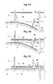
- Fig. 1 shows a skin insertion mechanism for perpendicular insertion of several, non-centrally positioned needles according to one embodiment of the invention.
- Fig 1A shows the skin insertion mechanism in the ready-to-use position
- Fig. 1B a sliding-bolt mechanism as release element
- Fig. 1C the skin insertion mechanism in the operation mode following insertion of the needles into the skin.
- Fig. 1A is a cross sectional view showing needles 1, which are fixedly positioned and hold perpendicularly by a needle support 2.
- a skin attachment plate 3 is coated with an adhesive layer 4 and has holes 5 opposing the tip of the needles.
- An individual's skin 6 is attached to the skin attachment plate 3 by an adhesive layer 4.
- a retraction mechanism consists in this embodiment of a spring-type mechanism comprising a telescopic guideways with an inner tube 7 fixed to the skin attachment plate and having a trip dog 8 at its other end. Tube 7 can slide within a shorter outer tube 9 fixed to the needle support to ensure a smooth and axially well-defined movement. Preferentially, one central or three to four such telescopic guideways distributed over the area of the attachment plate form the retraction mechanism.
- Fig. 1A shows the skin insertion mechanism in the ready-to-use position.
- a pressure spring 10 is pre-stressed between the needle support 2 and the trip dog 8 which is held by withholding means 11 attached to the needle support 2 by a slot and key construction 12 ensuring that the skin attachment plate 3 is sufficienly spread away from the needle support 2 to conceal the needles 1 and protect them from contacting the skin 6 (position 1) even if the skin attachment plate is pushed manually against the skin of the individual for attaching the adhesive layer 4 to the skin.
- Fig. 1B shows in a diagrammatic sectional top view the withholding means 11 and the slot and key construction 12 forming the release element constructed as a sliding bolt mechanism.
- the withholding means 11 are constructed such that sliding in the horizontal direction indicated by an arrow and actuated by pressing a handle 13 of the withholding means 11 against the needle support 2 exposes holes 14 large enough to allow the passage of the trip dog 8.
- the spring 10 can relax from the pre-stressed position and the skin attachment plate 3 together with the skin 6 attached by the adhesive layer 4 is rapidly pulled against the needle support and the tip of the needles 1, with sufficient velocity and force for piercing the skin and completely inserting an implantable portion of the needles into the skin.
- the resulting operational position 2 is shown in Fig 1C .
- Fig. 1C shows the skin insertion mechanism in the operational position (position 2) in a cross sectional view. Sliding the withholding means 11 in the slot and key construction 12 in the horizontal direction exposed the holes 14 and the trip dog 8 has passed through these holes. Using the telescopic guideways for a well-defined axial movement, the relaxing spring 10 has pulled the inner tube 7 fixed to the skin attachment plate 2 by effecting its sliding within the outer tube 9 fixed to the needle support. By this movement the needle support 2, the skin attachment plate 3 with the adhesive layer 4 and the attached skin 6 are now stacked up and the implantable part of the needles 1 are inserted into the skin.
- a construction can be chosen in which part of the retraction mechanism can be disconnected and removed following insertion of the needles into the skin.
- a construction is preferable if the skin insertion mechanism is used e.g. for an intradermal injection port, inserting the injection cannula into the skin and having a connecting element at the proximal end of the cannula, such as a septum or a connecting lock system, e.g. a Luer lock.
- Fig. 2 shows the skin insertion mechanism integrated into the housing 15 of a device requiring needle insertion into the skin at an angle of 45°.
- the mechanism and construction is essentially similar to that shown in Fig. 1 for perpendicular needle insertion and the same numbering is used for similar elements. Since the needle support is in this embodiment fused with the housing 15 of a device, the telescopic guideways of the retraction mechanism and the needles 1 are fixed to this housing.
- the telescopic guideways have an outer tube 7 fixed to a skin attachment plate at an angle of 45° sliding over an inner tube 9 fixed at an angle of 45° to the housing 15 of the device ensuring the movement at an angle of 45°.
- a spring 10 in this embodiment is situated inside the inner tube 9 and is a pull-spring hauled between the skin attachment plate 3 and the housing 15.
- Withholding means 11 are constructed as a sliding bolt mechanism withholding the tube 7 attached to the skin attachment plate 3, against the pull of the spring 10. This withholding means 11 can be released by pressing a handle 13 against the housing 15.
- the adhesive surface 4 for attachment to the skin has a larger surface than the skin attachment plate 3
- the adhesive surface 4 is fixed on the skin attachment plate 3 by a reduced surface, leaving an outer rim free, as shown in Detail A. Both designs prevent unintended detachment from the skin.
- Fig. 2A shows the insertion mechanism of the device in the ready-to-use mode and Fig. 2B in the operation mode with the needle inserted at an angle of 45° into the skin.
- Fig. 2B shows the insertion mechanism of the device in the ready-to-use mode and Fig. 2B in the operation mode with the needle inserted at an angle of 45° into the skin.
- this mechanism can also be used for the simultaneous insertion of several needles spread over the entire footprint of the device and having several functionalities.
- Fig. 3 shows elements of a skin insertion mechanism related to the one shown in Fig. 1 but having a skin attachment plate which is composed of a rigid and a flexible layer. Such a construction is useful if a deep insertion of the needles is requested which surpasses the overall height of the device. For simplicity, only the left part of the cross sectional scheme is shown.
- a flexible part 17 of a skin attachment plate represents the left side of a cone with central hole, or of a gable with a central slit, or alternatively a flexible plate fixed at one locus of its periphery to the needle support with holes for passage of needles which are not centrally located.
- Fig. 3 A shows a diagrammatic sectional view of a skin insertion mechanism in the ready-to-use mode.
- the needles 1 are covered and protected from touching the skin by the flexible part 17 which is coated with the adhesive layer 4.
- the retraction mechanism consists in this embodiment of two functional elements.
- a spring-type mechanism comprising a telescopic guideways and allowing the movement of the rigid part 16 of the skin attachment plate perpendicularly to the needle support similar to the mechanism shown in Fig. 1 is indicated only schematically by one inner tube 7 fixed to the skin attachment plate.
- the flexible part 17 of a spring-type material which is coated with the adhesive layer 4 represents the second functional element of the retraction mechanism. It is pre-stressed in the ready-to-use mode and bent away from the rigid part 16 of the skin attachment plate, concealing the tip of the needles.
- Withholding elements keeping the flexible part 17 pre-stressed can consist e.g. of several pin-shaped elements 18 protruding from the flexible part of the skin attachment plate and pushing onto the rigid part of the skin attachment plate with a hook-type construction 19.
- the retraction mechanism is actuated by a spring-type mechanism e.g. as described in Fig.1 and the movement of the skin attachment plate against the needle support 2 is indicated by the arrow (a).
- Fig. 3B shows an intermediary stage of the needle insertion process into the skin in which the rigid layer 16 of the skin attachment plate has almost reached the needle support 2.
- the flexible layer 17 of the skin attachment plate is still bent away from the rigid layer 16 by the hook-type construction 19 of the pin-shaped elements 18.
- Pulling the skin attached by the adhesive layer 4 against the tip of the needles 1 effects the piercing of the skin 6 but only a first part of insertion of the implantable part of the needles into the skin.
- Further movement of the skin attachment plate towards the needle support 2, indicated by the arrow (a) effects the passage of the extended bevel 20 of the pin-shaped withholding elements 18 through an opening of the needle support 2, and by this the bending of the withholding elements 18 in the direction of the arrow (b).
- This bending releases the hook-type construction 19 and the flexible layer 17 of the skin attachment plate can shoot from its pre-stressed, bent form in the direction of the arrow (c), pulling the skin attached by the adhesive layer towards the needle support.
- Fig. 3C shows the final position of the skin insertion mechanism in the operation mode.
- the rigid layer 16 and the flexible layer 17 of the skin attachment plate are together and firmly stacked up with the needle support 2 and fixed together by a hook 21.
- the skin 6 is attached by the adhesive layer 4 and the implantable part of the needles 1 is entirely inserted into the skin.
- Fig. 4 shows an injection device with two injection cannulas linked to a single syringe pump being actuated sequentially.
- an alternative embodiment of the invention is shown in which the skin attachment plate is fixed at one locus of its periphery to the needle support by a hinge-type mechanism.
- Such a construction allows using a very simple retraction mechanism without the need for special guideway mechanisms for ensuring a well-defined movement since the hinge-type mechanism attaching the skin attachment plate to the needle support guides the arcuate movement.
- Fig. 4A shows a cross-section of the device in the ready-to-use position.
- a needle support 2 is integrated into a casing 15.
- a skin attachment plate 3 coated with an adhesive layer 4 is linked to a needle support 2 by a hinge-type mechanism 22.
- a retraction mechanism consists in this embodiment of a spring-type mechanism comprising a pull-spring 10 hauled between the skin attachment plate 3 and the housing 15. Against the pull-force of the spring, the skin attachment plate 3 is spread away from the needle support 2 by withholding means consisting of a pressure-pin 23 attached to the skin attachment plate 3 and a flexible holding-back element 24 having a catch, which can be disengaged by pressing a release knob 25 which is sliding in a guideways 26.
- Pressing the release knob 25 releases the spring and results in an arcuate movement of the skin attachment plate 3 against the needle support 2 as indicated by the arrow, with the hinge-type mechanism 22 as pivot.
- the skin 6 attached to the skin attachment plate 3 by an adhesive 4 is rapidly pulled against the tip of the cannulas 1 and the implantable part of the needles gets inserted into the skin. It is advantageous if the needles 1 and the pressure-pin 23 are bent according to the radius of the arcuate movement.
- Fig. 4B shows a projected top view of the device with a syringe-type pump 27 having a piston 28 driven by a gear train 29 and a motor 30, under the control of control elements 32.
- the outlet of the syringe is split, ending in two delivery cannulas 1 and 1' which are actuated sequentially by valves 31 and 31'.
- a granulomatous response to the injection fluid at the injection site can be avoided, allowing the use of the device for an extended infusion time.
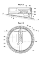
- a circular syringe pump with a toroidal barrel can be used, as shown in Fig. 5 .
- Fig. 5 shows the projected top view of an injection device with a circular syringe-type pump.
- This injection device with two injection cannulas linked to a single circular syringe pump has essentially similar features as the one described in Fig. 4 ; in particular it has also the same skin insertion mechanism for the cannulas and therefore only the elements different from the ones in Fig. 4 in this embodiment are shown.
- An arcuate barrel 33 of the circular syringe pump has the form of a segment of a toroidal tube.
- a piston 34 is arranged in the interior of the barrel and is provided with a seal 35 fitting tightly at the inner wall of the barrel.
- the piston is connected to a driving rod 36 which is circularly shaped for driving the piston through the entire length of the barrel.
- the driving rod 36 of the piston is formed preferentially in such a way that its movement is guided and supported by the inner surface of the barrel wall, e.g. by a brace 37 of optimized form and material for even movement with low friction.
- the inner side of the rod has a gear rim 38 which is driven by a gear drive 39.
- the gear drive is driven e.g. by a gear train and an electrical motor (not shown).
- Two cannulas are connected perpendicularly to the barrel, a first cannula 40 in the middle of the barrel and a second cannula 41 to the end piece 42 of the barrel.
- the end piece 42 of the barrel the short connecting channel 43 to the second delivery cannula 41 houses a movable stopper 44 which in a first position prevents flow of injection fluid from the barrel. In this stage fluid delivery takes place only through the first cannula 40 until about half of the total delivery volume is injected.
- the stopper 44 is pulled back at its handle 45 by a lever system 46, opening free flow from the barrel to the injection cannula 41.
- delivery of injection fluid through this first cannula stops automatically, resulting in a consecutive delivery of injection fluid through cannula 40 and 41 with a short overlap.
- a solution for the actuation of flow through the second cannula 41 by the lever system 46 comprises a buffer 47 fixedly mounted on the driving rod 36 which pushes the lever system in clockwise direction indicated by arrows but only for a short move sufficient for opening the connecting channel 43 to the second delivery cannula 41 by pulling the stopper 44 back behind the exit of the channel to the cannula 41 but still making the channel leak-proof.
- this can be achieved e.g. by a construction using a spring-type arm 48 of the lever system 46 which is held stressed on a stand 49 and relaxes falling down from the stand once the buffer 47 has pushed the spring-type arm 48 of the lever system over the edge of this stand, as indicated by the arrow.
- Detail A further indicates the possibility to use the movement of the skin attachment plate 3 against the needle support 2 for opening a seal at the tip of the cannula 41 (and 40, not shown in this Detail A).
- the septum 50 protecting and keeping closed the cannula is being pierced and pushed against a recess 51 in the needle support.
- a closed tube of thin wall covering the entire implantable part of the cannula can be used.
- Fig. 6 shows a cross-sectional view of a device with multiple needles with multiple functions inserted simultaneously into an individual's skin according to one embodiment of the subject invention.
- Multiple needles with several functions might be needed e.g. for delivery of injection fluid under the control of the simultaneous determination of analytes by means of diagnostic probes housed by the same device.
- diagnostic probes housed by the same device.
- a separate cannula delivering a calibration fluid might be needed and in addition needles as probes transmitting signals might be necessary to notify the patient in case of problems requiring intervention.
- the exemplified device could represent an embodiment representing a closed-loop system for tight glycemic control in diabetic or critically ill patients.
- Fig. 6A shows the device in the ready-to-use position pressed against the skin, thus forming an impression of the skin and ensuring a firm attachment of an adhesive surface 4 of a skin attachment plate 3 to the skin 6.
- the skin 6 is attached to the skin attachment plate 3 by an adhesive layer 4.
- Needle 52 is a cannula connected to an injection fluid pump 53; needles 54 represent probes transmitting signals.
- a diagnostic probe 55 in the shown example is a microdialysis probe, being representative of diagnostic probes having a flexible structure and therefore needing a guide needle 56 for insertion into the skin.
- the diagnostic probe 55 could be a sensor on a flexible support with an active surface at its tip.
- Needle 57 is a cannula connected to a pump for delivery of a calibration fluid from a delivery pump system 58 for in situ calibration of the diagnostic probe.
- a needle support 2 is integrated into a casing 15 and needles 52, 54, and 57 as well as a diagnostic probe 55 are fixedly attached to the needle support/casing.
- a microdialysis probe 55 is linked to a pump 59 delivering dialysis fluid through a central tube 60 to an active, semipermeable surface 61 and has an outlet 62 of the peripheral dialysate collecting tube linked to a flow-through analyte determinig system 63 with an outlet 64 to a waste collecting receptacle 65. Pump drive systems and the control means are not shown.
- the analyte determinig system 63 may further comprise means for determination of microdialysis recovery e.g. a sensing system measuring the residual concentration of an indicator substance contained in the dialysis fluid. If the molecular weight of this indicator substance is close to the molecular weight of the analyte, the magnitude of decrease in concentration of the indicator substance can be considered as indicative of the microdialysis recovery of the analyte.
- means for determination of microdialysis recovery e.g. a sensing system measuring the residual concentration of an indicator substance contained in the dialysis fluid. If the molecular weight of this indicator substance is close to the molecular weight of the analyte, the magnitude of decrease in concentration of the indicator substance can be considered as indicative of the microdialysis recovery of the analyte.
- a retraction mechanism for pulling the skin attachment plate 3 with the attached skin 6 against the needle support 2 consists of a spring-type mechanism essentially similar to the one discussed in Fig 1 but the spring 10 in this embodment is a pull-spring hauled between the skin attachment plate 3 and the housing 15.
- the retraction mechanism can be released by a release element which can be e.g. analogous to the ones discussed in Figs. 1 to 4 (only schematically depicted in this figure).
- the guide needle 56 can slide back along the diagnostic probe 55 actuated by a pressure spring 66 and guiding means 67 ensuring a smooth and axially well-defined movement. In the ready-to-use position shown in Fig.
- a withholding mechanism against the push-force of the spring 66 consisting e.g. of a withholding flage 68 at the end of the guide needle 56 and a holding-back element 69 having a catch 70.
- Fig. 6B shows the device in the operation mode, after actuation of the skin insertion mechanism.
- the skin attachment plate 3 with the adhesive layer 4 and the attached skin 6 have been pulled against the needle support 2 and are now stacked up.
- the implantable part of the needles has been inserted into the skin.
- Movement of the skin attachment plate 3 against the needle support 2 has also disengaged the withholding flage 68 of the guide needle of the diagnostic element 56 by bending-back the holding-back element 69 by way of pressure pins 71, which are fixed on the skin attachment plate, and the guide needle of the diagnostic element 56 has been partially retracted by the release of the spring 66 from its pre-stressed state, the end position being defined by a bumper 72.
- This mechanism ensures that the guide needle with the diagnostic element is inserted into the skin before partial retraction of the guide needle is actuated.
- the diagnostic element 56 is fixedly positioned relative to the casing 15, the active, semi-permeable surface 61 which is close to the tip, is after partial retraction of the guide needle exposed to subcutaneous tissue. This partial retraction of the guide needle can occur without interfering with the connections to the pump 59 and the analyte determining system 63.
- the partial retraction of the guide needle by a mechanism ensuring that this takes place strictly consecutively to guide needle insertion into the skin exposes the active surface of the diagnostic probe to subcutaneous tissue, but does not interfere with the connections to the pump 59 and to the analyte determining system, allows miniaturization, and in addition is easier and safer to use than removal of the guide needle.
- Periodic calibration of the diagnostic probe can be done in-situ by delivery of a calibration fluid from a delivery pump system 58 through the cannula 57 having its outlet close to the active surface of the diagnostic probe.
- the calibration fluid can be delivered directly to the flow-through analyte determinig system 63 through a connection 73.
- a pump system it is also possible instead of a pump system to use for the periodical calibration a simple manual system operated by the patient by pressing a knob or handle resulting in the delivery from e.g. a resevoir bag or a syringe a portion of calibration fluid.
- a simple manual system operated by the patient by pressing a knob or handle resulting in the delivery from e.g. a resevoir bag or a syringe a portion of calibration fluid e.g. a resevoir bag or a syringe a portion of calibration fluid.
- the principles for the construction of such delivery mechanisms manually operated by pressing on a knob or handle-type actuation interface for repetitive delivery of several equal portions of fluid from a reservoir are well known in drug delivery, e.g insulin pens, or laboratory devices or even household articles.
- Fig. 7 is a diagrammatic cross sectional view of a skin insertion mechanism for the cannula of an infusion set according to one embodiment of the invention which allows avoiding the manual insertion of the cannula into the skin.
- Such an insertion mechanism is not only overcoming the psychological hurdle of handling a needle and manually inserting it into the skin but is also less painful and safer, since needle insertion takes place at a defined and high velocity, unlike the big variations and holding-back attitude if needle insertion is done manually by the patient.
- Fig. 7 describes one possible constructional solution allowing these functions but many alternative constructional elements are also possible.
- Fig. 7A shows the skin insertion mechanism in the ready-to-use position applied with a functional package 74 onto the skin, after a cover foil keeping sterility during storage has been removed from the bottom of the package together with the cover foil protecting an adhesive (not shown).
- the release element is protected from unintended actuation and a rim 75 of the package helps the firm attachment to the skin 6 by pressing the adhesive layer 4 all around. After attachment to the skin the functional package 74 can be removed.
- the needle support 2 is attached to the skin attachment plate 3 by a stretched pull-spring 10 and the withholding means 11 with several, preferentially 3 to 6 pin-shaped elements 76 are ensuring that the skin attachment plate 3 is sufficienly spread away from the needle support 2 to conceal the cannula 1 and protect it from contacting the skin 6 (position 1).
- the withholding means 11 is reversibly linked to the needle support 2 through a linking component 78.
- the needle support 2 has tooth-like, preferentially 3 to 6, radial protrusions allowing not only an easy mounting of the pull-spring 10 but also engaging with a linking component 78 only at the periphery of these protrusions allowing a dis-engagement upon rotational movement of the linking component 78 relative to the needle support (as shown in Fig. 7C ), but several other constructions allowing dis-engagement are also possible.
- the linking component 78 has hook-type elements 79 and a catch mechanism 80 linking it to a cover 81 e.g. in an axial groove 82 in such a way that a limited axial but no rotational movement of the cover 81 against the linking component 78 is possible.
- the cover 81 has also protruding wedge-shaped elements 83 set against a wedge surface of the hook-type elements 79.
- Fig. 7B depicts the situation following pushing the cover 81 (position 2).
- the wedge-shaped elements 83 have bent the hook-type elements 79 radially, thus dis-engaging them from the withholding means 11. This has released the withholding means 11 and the stretched spring 10 has pulled the skin attachment plate 3 with the attached skin 6 against the needle support 2 effecting the insertion of the cannula 1 into the skin.
- a conical protrusion 84 of the needle support firmly attaches into a conical hole 85 in the skin attachment plate, but alternatively also e.g. hook-type elements can be used for linking the two together.
- insertion of the cannula into the skin most elements of the insertion mechanism can be removed by slight rotational movement of the cover 80 and lifting it off with the attached elements, as depicted in Figs. 7C and 7D .
- Fig. 7C shows a diagrammatic cross section following a slight rotational movement of the cover 81 respective to the skin attachment plate 3.
- the cross-sectional plane in this figure is slightly different from the one shown in Figs. 7A and 7B , turned to be between the tooth-like radial protrusions of the needle support 2, illustrative of the situation allowing dis-assembly of part of the skin insertion mechanism.
- the slight rotational movement of the cover 81 with the attached linking component 78 respective to the skin attachment plate 3 results in a dis-engagement between the needle support 2 and the linking component 78.
- protrusions 86 of the withholding means 11 engage with protrusions 87 linking the withholding means 11 to the cover 81. Since the catch mechanism 80 keeps the linking component 78 and the cover 81 together, lifting off the cover removes also the linking component 78 and the withholding means 11.
- Fig. 7D shows the infusion port attached to the skin during administration of the infusion fluid following removal of most elements of the insertion mechanism.
- the connecting element 88 of the needle support 2 e.g. a Luer lock-type conical hole or a septum, is now freely accessible for a corresponding connective element of a tube allowing linking to a pump system.
- a subcutaneous access device can be also used for skin insertion of a cannula of a single-use syringe or pen and be combined with mechanisms for needle retraction and protection after use as known in prior art for such systems.
- the retraction mechanism of the skin attachment plate or the release element can be electromagnetic, piezoelectric, pneumatic, etc. and the needles inserted into the skin can be any kind of pin or hollow needle with all types of functions requiring subcutaneous access.
- a skin insertion mechanism of needles described above are that the connections to the functional elements of the device having such a skin insertion mechanism have not to be flexible or manually established after skin insertion but can be manufactured as rigid connections, offering superior safety of operation and improved possibilities for miniaturization. Further, the danger that a needle is causing only an indentation of the skin rather than piercing and implantation is essentially eliminated by the forced movement of the attached skin against the needle.
- a number of needles with different functionalities can be inserted simultaneously sharing the same insertion mechanism and the location of these needles can be at any location of the skin contact surface of the device. There is also no limitation to the insertion depth and angle: the height and footprint of the device can be kept relatively small even for deep insertion.
Priority Applications (11)
| Application Number | Priority Date | Filing Date | Title |
|---|---|---|---|
| EP12163675.7A EP2650032A1 (de) | 2012-04-11 | 2012-04-11 | Subkutaner Nadeleinführungsmechanismus |
| CA2867526A CA2867526C (en) | 2012-04-11 | 2013-04-08 | Subcutaneous needle insertion mechanism |
| KR1020147031512A KR102143025B1 (ko) | 2012-04-11 | 2013-04-08 | 피하주사 바늘 삽입 메커니즘 |
| EP13715203.9A EP2836255B1 (de) | 2012-04-11 | 2013-04-08 | Subkutaner nadeleinführungsmechanismus |
| JP2015504922A JP6113830B2 (ja) | 2012-04-11 | 2013-04-08 | 皮下針挿入メカニズム |
| PCT/EP2013/057327 WO2013153042A1 (en) | 2012-04-11 | 2013-04-08 | Subcutaneous needle insertion mechanism |
| ES13715203.9T ES2611141T3 (es) | 2012-04-11 | 2013-04-08 | Mecanismo de introducción de una aguja subcutánea |
| CN201380019477.8A CN104302333B (zh) | 2012-04-11 | 2013-04-08 | 皮下针插入机构 |
| DK13715203.9T DK2836255T3 (en) | 2012-04-11 | 2013-04-08 | Subcutaneous needle insertion mechanism |
| US14/391,402 US10076356B2 (en) | 2012-04-11 | 2013-04-08 | Subcutaneous needle insertion mechanism |
| HK15101695.9A HK1201219A1 (en) | 2012-04-11 | 2015-02-13 | Subcutaneous needle insertion mechanism |
Applications Claiming Priority (1)
| Application Number | Priority Date | Filing Date | Title |
|---|---|---|---|
| EP12163675.7A EP2650032A1 (de) | 2012-04-11 | 2012-04-11 | Subkutaner Nadeleinführungsmechanismus |
Publications (1)
| Publication Number | Publication Date |
|---|---|
| EP2650032A1 true EP2650032A1 (de) | 2013-10-16 |
Family
ID=48083162
Family Applications (2)
| Application Number | Title | Priority Date | Filing Date |
|---|---|---|---|
| EP12163675.7A Withdrawn EP2650032A1 (de) | 2012-04-11 | 2012-04-11 | Subkutaner Nadeleinführungsmechanismus |
| EP13715203.9A Active EP2836255B1 (de) | 2012-04-11 | 2013-04-08 | Subkutaner nadeleinführungsmechanismus |
Family Applications After (1)
| Application Number | Title | Priority Date | Filing Date |
|---|---|---|---|
| EP13715203.9A Active EP2836255B1 (de) | 2012-04-11 | 2013-04-08 | Subkutaner nadeleinführungsmechanismus |
Country Status (10)
| Country | Link |
|---|---|
| US (1) | US10076356B2 (de) |
| EP (2) | EP2650032A1 (de) |
| JP (1) | JP6113830B2 (de) |
| KR (1) | KR102143025B1 (de) |
| CN (1) | CN104302333B (de) |
| CA (1) | CA2867526C (de) |
| DK (1) | DK2836255T3 (de) |
| ES (1) | ES2611141T3 (de) |
| HK (1) | HK1201219A1 (de) |
| WO (1) | WO2013153042A1 (de) |
Cited By (3)
| Publication number | Priority date | Publication date | Assignee | Title |
|---|---|---|---|---|
| CN109044422A (zh) * | 2018-08-22 | 2018-12-21 | 平荧 | 微细软组织线锉真皮下潜行分离系统 |
| EP4260886A1 (de) * | 2022-04-14 | 2023-10-18 | PharmaSens AG | Pflasterartige medzinische vorrichtung mit beweglicher nadelschutzhülse |
| WO2023198343A1 (en) * | 2022-04-14 | 2023-10-19 | Pharmasens Ag | Patch-like medical device |
Families Citing this family (24)
| Publication number | Priority date | Publication date | Assignee | Title |
|---|---|---|---|---|
| EP2195052B1 (de) | 2007-10-02 | 2019-09-04 | Medimop Medical Projects Ltd. | Externe arzneimittelpumpe |
| EP2436311A1 (de) * | 2010-10-04 | 2012-04-04 | PharmaSens AG | Diagnostische Vorrichtung |
| EP3236882B1 (de) | 2014-12-23 | 2020-02-05 | Automed Pty Ltd | Ausgabevorrichtung, system und zugehöriges verfahren |
| US10576207B2 (en) | 2015-10-09 | 2020-03-03 | West Pharma. Services IL, Ltd. | Angled syringe patch injector |
| JP7017512B2 (ja) | 2015-10-09 | 2022-02-08 | ウェスト ファーマ サービシーズ イスラエル リミテッド | 充填済流体容器の屈曲流体路型付属物 |
| WO2017127215A1 (en) | 2016-01-21 | 2017-07-27 | Medimop Medical Projects Ltd. | Needle insertion and retraction mechanism |
| JP6885960B2 (ja) | 2016-01-21 | 2021-06-16 | ウェスト ファーマ サービシーズ イスラエル リミテッド | 視覚的インジケータを有する薬剤デリバリデバイス |
| EP3711793B1 (de) | 2016-01-21 | 2021-12-01 | West Pharma Services IL, Ltd. | Verfahren zur verbindung einer patrone mit einem automatischen injektor |
| WO2017161076A1 (en) | 2016-03-16 | 2017-09-21 | Medimop Medical Projects Ltd. | Staged telescopic screw assembly having different visual indicators |
| CN109562229B (zh) | 2016-08-01 | 2021-07-13 | 西医药服务以色列有限公司 | 抗旋转药筒销 |
| CN110035783B (zh) * | 2016-09-27 | 2022-04-12 | 赛诺菲-安万特德国有限公司 | 药剂递送装置 |
| CA3050721A1 (en) * | 2017-01-23 | 2018-07-26 | Abbott Diabetes Care Inc. | Systems, devices and methods for analyte sensor insertion |
| CN113855913A (zh) | 2017-05-30 | 2021-12-31 | 西部制药服务有限公司(以色列) | 用于穿戴式注射器的模块化驱动机构 |
| KR101975198B1 (ko) * | 2017-07-24 | 2019-08-28 | 최규동 | 하이브리드 연속혈당측정 시스템 |
| EP3650061A4 (de) * | 2017-09-08 | 2020-07-01 | Terumo Kabushiki Kaisha | Punktionsvorrichtung |
| US20220080116A1 (en) * | 2018-12-25 | 2022-03-17 | Hirosaki University | Medicine administering device and medicine administering system |
| CN113646023B (zh) * | 2019-02-22 | 2023-07-21 | 德卡产品有限公司 | 输液器以及插入物组件系统和方法 |
| US20210030319A1 (en) * | 2019-08-02 | 2021-02-04 | Bionime Corporation | Physiological signal monitoring system for fast assembly |
| KR102403085B1 (ko) * | 2019-12-17 | 2022-05-30 | 이오플로우(주) | 약액 주입 장치 |
| WO2021118282A2 (ko) * | 2019-12-11 | 2021-06-17 | 이오플로우(주) | 약액 주입 장치 |
| US11957542B2 (en) | 2020-04-30 | 2024-04-16 | Automed Patent Holdco, Llc | Sensing complete injection for animal injection device |
| US11738140B2 (en) * | 2021-01-15 | 2023-08-29 | Medtronic Minimed, Inc. | Insertion device with linkage assembly |
| KR102412806B1 (ko) * | 2021-08-27 | 2022-06-23 | 김성우 | 약액 주입장치 |
| WO2024073445A1 (en) * | 2022-09-30 | 2024-04-04 | Ocelot Bio, Inc. | Mixed vasopressin receptor agonist-antagonist for modulating mean arterial pressure |
Citations (9)
| Publication number | Priority date | Publication date | Assignee | Title |
|---|---|---|---|---|
| EP0825882A1 (de) | 1995-05-22 | 1998-03-04 | F. Hoffmann-La Roche Ag | An der haut haftende medizinische vorrichtung |
| US5931814A (en) | 1994-10-28 | 1999-08-03 | Hoffmann-La Roche Inc. | Dermally affixed injection device |
| US20020022798A1 (en) * | 2000-08-18 | 2002-02-21 | Connelly Robert I. | Constant rate fluid delivery device with selectable flow rate and titratable bolus button |
| WO2003055540A1 (en) | 2001-12-28 | 2003-07-10 | Microbiotech/Se Ab | Microdialysis probe with inserting means and assembly |
| WO2004030728A2 (en) * | 2002-10-07 | 2004-04-15 | Novo Nordisk A/S | Needle insertion device |
| WO2005063115A1 (en) | 2003-12-22 | 2005-07-14 | Hadvary Paul | Dermallly affixed sensor device |
| US20080004515A1 (en) | 2006-06-30 | 2008-01-03 | Abbott Diabetes Care, Inc. | Integrated Analyte Sensor and Infusion Device and Methods Therefor |
| EP2436311A1 (de) * | 2010-10-04 | 2012-04-04 | PharmaSens AG | Diagnostische Vorrichtung |
| EP2438938A1 (de) * | 2010-10-11 | 2012-04-11 | PharmaSens AG | Spritzenartige Pumpe |
Family Cites Families (13)
| Publication number | Priority date | Publication date | Assignee | Title |
|---|---|---|---|---|
| IL109294A (en) * | 1994-04-12 | 1998-02-08 | Wais Med Ltd | Surgical instrument for impact insertion of an intraosseous trocar- needle |
| US5586553A (en) * | 1995-02-16 | 1996-12-24 | Minimed Inc. | Transcutaneous sensor insertion set |
| ZA9610374B (en) * | 1995-12-11 | 1997-06-23 | Elan Med Tech | Cartridge-based drug delivery device |
| US6607509B2 (en) * | 1997-12-31 | 2003-08-19 | Medtronic Minimed, Inc. | Insertion device for an insertion set and method of using the same |
| US6210369B1 (en) * | 1997-12-16 | 2001-04-03 | Meridian Medical Technologies Inc. | Automatic injector |
| US6424847B1 (en) * | 1999-02-25 | 2002-07-23 | Medtronic Minimed, Inc. | Glucose monitor calibration methods |
| EP1556103A1 (de) * | 2002-10-07 | 2005-07-27 | Novo Nordisk A/S | Nadelvorrichtung mit einer vielzahl von nadeln |
| ATE357939T1 (de) * | 2003-07-08 | 2007-04-15 | Novo Nordisk As | Tragbares medikamentenabgabegerät mit einer eingekapselten nadel |
| CN101426542A (zh) * | 2006-04-26 | 2009-05-06 | 诺沃-诺迪斯克有限公司 | 含经涂覆的密封构件的包装件中的可安装在表皮上的装置 |
| EP2054109B1 (de) * | 2006-08-24 | 2017-12-13 | F. Hoffmann-La Roche AG | Einführvorrichtung für einführköpfe, insbesondere für infusionsstents |
| US20080243053A1 (en) * | 2007-03-30 | 2008-10-02 | Animas Corporation | Method for inserting a cannula into an infusion site |
| CN102089021A (zh) * | 2008-07-07 | 2011-06-08 | 优诺医疗有限公司 | 用于经皮部件的插入器 |
| US9370621B2 (en) * | 2008-12-16 | 2016-06-21 | Medtronic Minimed, Inc. | Needle insertion systems and methods |
-
2012
- 2012-04-11 EP EP12163675.7A patent/EP2650032A1/de not_active Withdrawn
-
2013
- 2013-04-08 KR KR1020147031512A patent/KR102143025B1/ko active IP Right Grant
- 2013-04-08 CN CN201380019477.8A patent/CN104302333B/zh active Active
- 2013-04-08 WO PCT/EP2013/057327 patent/WO2013153042A1/en active Application Filing
- 2013-04-08 CA CA2867526A patent/CA2867526C/en active Active
- 2013-04-08 EP EP13715203.9A patent/EP2836255B1/de active Active
- 2013-04-08 JP JP2015504922A patent/JP6113830B2/ja active Active
- 2013-04-08 ES ES13715203.9T patent/ES2611141T3/es active Active
- 2013-04-08 US US14/391,402 patent/US10076356B2/en active Active
- 2013-04-08 DK DK13715203.9T patent/DK2836255T3/en active
-
2015
- 2015-02-13 HK HK15101695.9A patent/HK1201219A1/xx unknown
Patent Citations (9)
| Publication number | Priority date | Publication date | Assignee | Title |
|---|---|---|---|---|
| US5931814A (en) | 1994-10-28 | 1999-08-03 | Hoffmann-La Roche Inc. | Dermally affixed injection device |
| EP0825882A1 (de) | 1995-05-22 | 1998-03-04 | F. Hoffmann-La Roche Ag | An der haut haftende medizinische vorrichtung |
| US20020022798A1 (en) * | 2000-08-18 | 2002-02-21 | Connelly Robert I. | Constant rate fluid delivery device with selectable flow rate and titratable bolus button |
| WO2003055540A1 (en) | 2001-12-28 | 2003-07-10 | Microbiotech/Se Ab | Microdialysis probe with inserting means and assembly |
| WO2004030728A2 (en) * | 2002-10-07 | 2004-04-15 | Novo Nordisk A/S | Needle insertion device |
| WO2005063115A1 (en) | 2003-12-22 | 2005-07-14 | Hadvary Paul | Dermallly affixed sensor device |
| US20080004515A1 (en) | 2006-06-30 | 2008-01-03 | Abbott Diabetes Care, Inc. | Integrated Analyte Sensor and Infusion Device and Methods Therefor |
| EP2436311A1 (de) * | 2010-10-04 | 2012-04-04 | PharmaSens AG | Diagnostische Vorrichtung |
| EP2438938A1 (de) * | 2010-10-11 | 2012-04-11 | PharmaSens AG | Spritzenartige Pumpe |
Non-Patent Citations (1)
| Title |
|---|
| TRAJANO- SKI ET AL., DIABETES CARE, vol. 20, 1997, pages 1114 - 1121 |
Cited By (3)
| Publication number | Priority date | Publication date | Assignee | Title |
|---|---|---|---|---|
| CN109044422A (zh) * | 2018-08-22 | 2018-12-21 | 平荧 | 微细软组织线锉真皮下潜行分离系统 |
| EP4260886A1 (de) * | 2022-04-14 | 2023-10-18 | PharmaSens AG | Pflasterartige medzinische vorrichtung mit beweglicher nadelschutzhülse |
| WO2023198343A1 (en) * | 2022-04-14 | 2023-10-19 | Pharmasens Ag | Patch-like medical device |
Also Published As
| Publication number | Publication date |
|---|---|
| JP2015518396A (ja) | 2015-07-02 |
| KR20150005604A (ko) | 2015-01-14 |
| WO2013153042A1 (en) | 2013-10-17 |
| CN104302333B (zh) | 2017-01-11 |
| EP2836255A1 (de) | 2015-02-18 |
| EP2836255B1 (de) | 2016-10-19 |
| JP6113830B2 (ja) | 2017-04-12 |
| US10076356B2 (en) | 2018-09-18 |
| CA2867526A1 (en) | 2013-10-17 |
| ES2611141T3 (es) | 2017-05-05 |
| KR102143025B1 (ko) | 2020-08-11 |
| CA2867526C (en) | 2020-01-21 |
| US20150141776A1 (en) | 2015-05-21 |
| DK2836255T3 (en) | 2017-02-06 |
| HK1201219A1 (en) | 2015-08-28 |
| CN104302333A (zh) | 2015-01-21 |
Similar Documents
| Publication | Publication Date | Title |
|---|---|---|
| EP2836255B1 (de) | Subkutaner nadeleinführungsmechanismus | |
| EP2624757B1 (de) | Diagnosevorrichtung | |
| EP2907535B1 (de) | Spritzenartige Pumpe | |
| US7981085B2 (en) | Internal needle inserter | |
| JP4509100B2 (ja) | 取り外し可能な針挿入作動部を有する皮膚に取り付け可能な注入装置 | |
| EP2836254B1 (de) | Durch manuellen druck aktivierter anwendungsmechanismus | |
| JP2014510573A (ja) | 薬物送達注入セット用の自蔵式ねじりばね挿入器 | |
| EP2694135B1 (de) | An der haut befestigte vorrichtung für intravenösen zugang | |
| EP1554001B1 (de) | Nadel-insertionsvorrichtung |
Legal Events
| Date | Code | Title | Description |
|---|---|---|---|
| PUAI | Public reference made under article 153(3) epc to a published international application that has entered the european phase |
Free format text: ORIGINAL CODE: 0009012 |
|
| AK | Designated contracting states |
Kind code of ref document: A1 Designated state(s): AL AT BE BG CH CY CZ DE DK EE ES FI FR GB GR HR HU IE IS IT LI LT LU LV MC MK MT NL NO PL PT RO RS SE SI SK SM TR |
|
| AX | Request for extension of the european patent |
Extension state: BA ME |
|
| STAA | Information on the status of an ep patent application or granted ep patent |
Free format text: STATUS: THE APPLICATION IS DEEMED TO BE WITHDRAWN |
|
| 18D | Application deemed to be withdrawn |
Effective date: 20140417 |