EP1037229A1 - Hub-Schiebe-Schalter - Google Patents
Hub-Schiebe-Schalter Download PDFInfo
- Publication number
- EP1037229A1 EP1037229A1 EP00104473A EP00104473A EP1037229A1 EP 1037229 A1 EP1037229 A1 EP 1037229A1 EP 00104473 A EP00104473 A EP 00104473A EP 00104473 A EP00104473 A EP 00104473A EP 1037229 A1 EP1037229 A1 EP 1037229A1
- Authority
- EP
- European Patent Office
- Prior art keywords
- actuating element
- lift
- actuating
- slide switch
- switch according
- Prior art date
- Legal status (The legal status is an assumption and is not a legal conclusion. Google has not performed a legal analysis and makes no representation as to the accuracy of the status listed.)
- Granted
Links
- 238000013459 approach Methods 0.000 description 9
- 238000009434 installation Methods 0.000 description 3
- 238000004519 manufacturing process Methods 0.000 description 3
- 238000000034 method Methods 0.000 description 2
- 238000013461 design Methods 0.000 description 1
- 238000001514 detection method Methods 0.000 description 1
- 238000011161 development Methods 0.000 description 1
- 238000005553 drilling Methods 0.000 description 1
- 230000002349 favourable effect Effects 0.000 description 1
- 230000009760 functional impairment Effects 0.000 description 1
- 230000010354 integration Effects 0.000 description 1
- 238000012546 transfer Methods 0.000 description 1
Images

Classifications
-
- H—ELECTRICITY
- H01—ELECTRIC ELEMENTS
- H01H—ELECTRIC SWITCHES; RELAYS; SELECTORS; EMERGENCY PROTECTIVE DEVICES
- H01H25/00—Switches with compound movement of handle or other operating part
- H01H25/006—Switches with compound movement of handle or other operating part having an operating member slidable in a plane in one direction and pivotable around an axis located in the sliding plane perpendicular to the sliding direction
-
- H—ELECTRICITY
- H01—ELECTRIC ELEMENTS
- H01H—ELECTRIC SWITCHES; RELAYS; SELECTORS; EMERGENCY PROTECTIVE DEVICES
- H01H21/00—Switches operated by an operating part in the form of a pivotable member acted upon directly by a solid body, e.g. by a hand
- H01H21/02—Details
- H01H21/18—Movable parts; Contacts mounted thereon
- H01H21/22—Operating parts, e.g. handle
- H01H2021/225—Operating parts, e.g. handle with push-pull operation, e.g. which can be pivoted in both directions by pushing or pulling on the same extremity of the operating member
-
- H—ELECTRICITY
- H01—ELECTRIC ELEMENTS
- H01H—ELECTRIC SWITCHES; RELAYS; SELECTORS; EMERGENCY PROTECTIVE DEVICES
- H01H2215/00—Tactile feedback
- H01H2215/004—Collapsible dome or bubble
-
- H—ELECTRICITY
- H01—ELECTRIC ELEMENTS
- H01H—ELECTRIC SWITCHES; RELAYS; SELECTORS; EMERGENCY PROTECTIVE DEVICES
- H01H2217/00—Facilitation of operation; Human engineering
- H01H2217/04—Mimics of controlled apparatus or symbol
-
- H—ELECTRICITY
- H01—ELECTRIC ELEMENTS
- H01H—ELECTRIC SWITCHES; RELAYS; SELECTORS; EMERGENCY PROTECTIVE DEVICES
- H01H2221/00—Actuators
- H01H2221/078—Different operating parts on a bigger one
-
- H—ELECTRICITY
- H01—ELECTRIC ELEMENTS
- H01H—ELECTRIC SWITCHES; RELAYS; SELECTORS; EMERGENCY PROTECTIVE DEVICES
- H01H23/00—Tumbler or rocker switches, i.e. switches characterised by being operated by rocking an operating member in the form of a rocker button
- H01H23/003—Tumbler or rocker switches, i.e. switches characterised by being operated by rocking an operating member in the form of a rocker button with more than one electrically distinguishable condition in one or both positions
-
- H—ELECTRICITY
- H01—ELECTRIC ELEMENTS
- H01H—ELECTRIC SWITCHES; RELAYS; SELECTORS; EMERGENCY PROTECTIVE DEVICES
- H01H2300/00—Orthogonal indexing scheme relating to electric switches, relays, selectors or emergency protective devices covered by H01H
- H01H2300/006—Application power roofs
Definitions
- the invention relates to a lift and slide switch, especially for the lifting and sliding roof of a motor vehicle, with a housing, a first actuator for the Sliding movement and a second actuator for that Lifting movement of the roof, each with a reset device automatically return to their starting position Actuators each via a switching element Actuate switch contacts.
- the object is achieved in that the second actuator in the first actuator is integrated, with both actuators in the housing stored and the switching elements designed as rotary switching elements are.
- the compact design of the lift and slide switch is due to the Integration of one actuator in the other given. Because each actuator is stored separately in the housing is applied to the actuators from the outside Movement overlaps do not lead to a functional impairment to lead.
- the assignment of one rotary switching element each is relative to an actuator to implement simple and inexpensive switch mechanics. Furthermore, the arrangement of a rotary switching element with relatively simple means without complex guides perform.
- the first stage of each switch position causes one slow movement of the roof while the second stage one rapid movement of the roof up to a stop position Consequence.
- first actuator as a sliding button and the second actuator designed as a pull / push button.
- This configuration enables a clear assignment of the switch functions to those of the lifting sunroof. So they are Slide button the sliding movements and the pull / push button the Assigned lifting movements of the roof.
- each actuator via the associated housing side mounted rotary switching element a switching contact and in each second switch position another switch contact one Safety mat applied.
- the switch contacts of the switch mat in spaced apart Domes arranged and by a common operating plate covered. This is the tactile detection of the switch positions possible and can by changing the mechanical Properties of the safety mat can be varied.
- Every safety mat thus represents a direction of movement of the roof.
- the switching mats assigned to a rotary switching element arranged in such a way that one dome each Safety mat essentially in a common level one dome of the other switch mat and the other Point the domes of the safety mats in opposite directions. It also expediently forms the essentially common one Plane of the dome a plane with the axis of rotation of the Rotary switching element.
- each actuator To convert the sliding movement or the pull / push movement the actuating elements in rotary movements for the rotary switching elements, is according to a further embodiment of the invention between each actuator and the associated rotary switch a deflection device is arranged.
- the first actuating element assigned deflection device a web, at one end two through lateral holes in the actuator extending pegs are arranged which simultaneously to Serve storage of the actuator in the housing, and on its other end connected to the rotary switching element, two bearing pins engaging in housing bores are.
- the deflection device is thus inexpensive to manufacture.
- To ensure stable storage in the immediate vicinity of the assigned To create safety mats preferably includes the second Actuator associated deflector two-armed articulated joint, one arm on the actuator is attached and at the other with the rotary switching element connected arm two engaging in housing bores Bearing journals are attached.
- each Rotary switching element For the punctiform loading of the actuating plates of the shift mats arranged offset to each other, each Rotary switching element two Z-shaped actuation approaches on. This shape saves material with the manufacture of the rotary switching element.
- Adequate and relatively easy to manufacture storage is achieved in that the first actuating element with parallel to the pin of the deflection device and spaced guide pin is provided, the pin and the guide pins for mounting the actuating element engage in corresponding slots in the housing.
- the first actuating element only has two guide pins and is in motion limited by the elongated holes.
- the second actuating element preferably bears in the area in which the deflection device is formed, lateral trunnion, which in corresponding holes of the Intervene.
- the arrangement of the side journals in the holes allows the pivoting movement of the second Actuator in both the pulling and pushing directions.
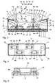
- the stroke-slide switch essentially comprises a rectangular one Housing 1 with a protruding beyond the housing 1 Aperture 2, the housing opening 1 receiving opening covered. On the panel 2 are optionally backlit Symbols 3 for the functions of the lift and slide switch pictured. At the bottom of the housing 1 is a Connection collar 52 formed.
- the panel 2 has an installation opening 4 for a first actuating element 5, which is designed as a slide button.
- the installation opening 4 is through webs 6 on the long sides and limited by engagement troughs 7 on the end faces.
- a second actuating element 8 is integrated, on which a symbol 9 for a switch function is shown is.
- the second actuating element 8 projects into a rectangular recess 10 of the first actuating element 5, with the recess 10 in the region of an end face an engagement trough 11 for reaching behind as a pull / push button trained second actuator 8 provided is.
- the first actuating element 5 is a deflection device 12 assigned, the application of an assigned rotary switching element 13 allows.
- the deflection device 12 comprises a web 14, at one end 15 two through lateral Bores 16 of the first actuating element 5 extending Pins 17 are arranged.
- the pin 17 protrude in her further course in corresponding slots 18 of the Housing 1 and thus serve to support the first actuating element 5 in the housing 1.
- the other end 19 of the web 14 is connected to the rotary switching element 13 and has two Bearing pin 20, which in corresponding housing bores 21st intervention.
- the rotary switching element 13 is mutually Z-shaped arranged actuating approaches 22, 23 for loading one actuating plate 24, 25 each Safety mat 26, 27 provided.
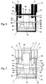
- the first actuator 5 contributes two guide pins to provide stable storage 28 that are parallel as well as spaced apart from the tenons 17 of the web 14 of the deflection device 12 in elongated holes 29 of the housing 5 engage, the elongated holes 18, 29 die Limit the sliding movement of the first actuating element 5.
- the second actuating element 8 also acts with a deflection device 30 together, which is a two-armed articulated joint 31 includes.
- One arm 32 of the articulated joint 31 is on the second actuator 8 attached.
- the other arm 33 is connected to a rotary switching element 34 and points two bearing pins 36 engaging in housing bores 35.
- the rotary switching element 34 corresponds to the rotary switching element 13 also with two Z-shaped actuating approaches 37, 38 for loading one actuating plate each 39, 40 of a switch mat 41, 42 provided.
- the Storage of the second actuating element 8 takes place via lateral bearing pin 43, which in corresponding holes 44 of the housing 5 are used. To make this storage possible has the first actuating element 5 in the area the journal 43 of the second actuating element 8 frankings 63 on.
- the structure of the on a connection contacts 45 Printed circuit board 46 arranged switching mats 26, 27, 41, 42 is essentially the same and is described below using the Switch mat 27 explained in detail.
- the switching mat 27 includes two adjacent and spaced apart Dome 47, 48, each dome 47, 48 having a switch contact 49, 50 records. In the upper area, the two domes 47, 48 covered by the common actuating plate 25.
- the order of two safety mats 26, 27 and 41, 42 respectively such that these are parallel to one another and alongside one another offset the rotary switching element 13 and 34 are assigned.
- a dome 48 of a switch mat 26, 41 in a substantially common plane 51 with the Dome 48 of the other switch mat 27, 42 and the other Dome 47 of the switching mats 26, 27, 41, 42 face in opposite directions Directions.
- the essentially common level 51 the dome 48 forms a plane with the axis of rotation of the assigned rotary switching element 13 or 34.
- the first actuating element is moved into a switching division 55 second stage takes place on the basis of larger switching path after the buckling already described of the dome 47 also the buckling of the dome 48 of the safety mat 26 and the switch contact 50 closes another Circuit that opens an opening sliding movement of the roof to its end stop.
- the end stop is also after the release of the actuator 5 reached, which Let go of the return movement by resetting the domes 47, 48 of the actuating element 5 in the zero position 53 causes.
- the switch positions 56, 57 of the first actuating element 5 cause a sliding movement closing the roof, the Actuation approach 23 of the rotary switching element 13 on the dome 47, 48 of the safety mat 27 acts and the closing of Circuits causes.
- To overuse the To prevent switch mechanism hit the pin 17 and the bearing pins 20 in the switching positions 55, 57 of the second Step on the corresponding end faces of the elongated holes 18, 29 and prevent a further sliding movement of the actuating element 5.
- the action on the second actuating element 8 causes a lifting movement of the lifting sunroof.
- the pressure direction goes the same in a switching position 59 first Level above, wherein the actuator 8 with its molded Bearing pin 43 in the bores 44 of the housing 1 is pivoted. Due to the associated with the actuator 8 The rotary switching element 34 experiences deflection device 30 a rightward rotation.
- the one on the actuator 8 attached arm 32 and the one with the rotary switching element 34 related arm 33 move here through the articulated joint 31 and the arrangement of the bearing pins 36 in opposite directions in the housing bores 35.
- the second actuating element is pressurized 8 in a switching position 60 second stage, the Switching path covered next to the buckling already explained of the mandrel 47 also the buckling of the dome 48 of the safety mat 42 and the switch contact 50 closes another Circuit that an opening stroke of the roof up to End stop causes.
- the end stop is also released after you let go of the actuator 8 reached, releasing the resetting movement by resetting the domes 47, 48 of the actuating element 8 in the zero position 58.
- the switching positions 61, 62 of the second actuating element 8, by the actuation of the actuating element 8 can be reached in the direction of pull, cause the roof closing stroke movement, the actuating projection 37 of the Rotary switching element 34 on the domes 47, 48 of the switching mat 41 acts and the closing of two further circuits successively.
- the processes take place in the above explained way.
Landscapes
- Power-Operated Mechanisms For Wings (AREA)
- Tumbler Switches (AREA)
Abstract
Description
- Fig.1
- eine Draufsicht auf einen erfindungsgemäßen Hub-Schiebe-Schalter,
- Fig.2
- eine Ansicht der Darstellung nach Fig. 1 in Richtung des Pfeiles II,
- Fig.3
- einen Schnitt durch die Darstellung nach Fig. 1 gemäß der Linie III-III,
- Fig.4
- einen Schnitt durch die Darstellung nach Fig. 3 gemäß der Linie IV-IV,
- Fig.5
- eine vergrößerte Darstellung einer Einzelheit V nach Fig. 4 im Schnitt,
- Fig.6
- einen Schnitt durch die Darstellung nach Fig. 3 gemäß der Linie VI-VI und
- Fig.7
- einen Schnitt durch die Darstellung nach Fig. 3 gemäß der Linie VII-VII.
- 1.
- Gehäuse
- 2.
- Blende
- 3.
- Symbol
- 4.
- Einbauöffnung
- 5.
- 1. Betätigungselement
- 6.
- Steg
- 7.
- Eingriffmulde
- 8.
- 2. Betätigungselement
- 9.
- Symbol
- 10.
- Ausnehmung
- 11.
- Eingriffmulde
- 12.
- Umlenkeinrichtung
- 13.
- Drehschaltglied
- 14.
- Steg
- 15.
- Ende
- 16.
- Bohrungen
- 17.
- Zapfen
- 18.
- Langloch
- 19.
- Ende
- 20.
- Lagerzapfen
- 21.
- Gehäusebohrung
- 22.
- Betätigungsansatz
- 23.
- Betätigungsansatz
- 24.
- Betätigungsplatte
- 25.
- Betätigungsplatte
- 26.
- Schaltmatte
- 27.
- Schaltmatte
- 28.
- Führungszapfen
- 29.
- Langloch
- 30.
- Umlenkeinrichtung
- 31
- . Knickgelenk
- 32.
- Arm
- 33.
- Arm
- 34.
- Drehschaltglied
- 35.
- Gehäusebohrung
- 36.
- Lagerzapfen
- 37.
- Betätigungsansatz
- 38.
- Betätigungsansatz
- 39.
- Betätigungsplatte
- 40.
- Betätigungsplatte
- 41.
- Schaltmatte
- 42.
- Schaltmatte
- 43.
- Lagerzapfen
- 44.
- Bohrung
- 45.
- Anschlußkontakt
- 46.
- Leiterplatte
- 47.
- Dom
- 48.
- Dom
- 49.
- Schaltkontakt
- 50.
- Schaltkontakt
- 51.
- Ebene
- 52.
- Anschlußkragen
- 53.
- Null-Stellung
- 54.
- Schaltstellung
- 55.
- Schaltstellung
- 56.
- Schaltstellung
- 57.
- Schaltstellung
- 58.
- Null-Stellung
- 59.
- Schaltstellung
- 60.
- Schaltstellung
- 61.
- Schaltstellung
- 62.
- Schaltstellung
- 63.
- Freimachung
Claims (14)
- Hub-Schiebe-Schalter, insbesondere für das Hub-Schiebedach eines Kraftfahrzeuges, mit einem Gehäuse (1), einem ersten Betätigungselement (5) für die Schiebebewegung und einem zweiten Betätigungselement (8) für die Hubbewegung des Daches, wobei die jeweils durch eine Rückstelleinrichtung selbsttätig in ihre Ausgangsstellung zurückgehenden Betätigungselemente (5, 8) jeweils über ein Schaltglied Schaltkontakte (49, 50) beaufschlagen, dadurch gekennzeichnet, daß das zweite Betätigungselement (8) in dem ersten Betätigungselement (5) integriert ist, wobei beide Betätigungselemente (5, 8) in dem Gehäuse (1) gelagert und die Schaltglieder als Drehschaltglieder (13, 34) ausgebildet sind.
- Hub-Schiebe-Schalter nach Anspruch 1, dadurch gekennzeichnet, daß den Betätigungselementen (5, 8) für das Öffnen und Schließen des Daches jeweils zweistufige Schaltstellungen (54, 55, 56, 57, 59, 60, 61, 62) zugeordnet sind.
- Hub-Schiebe-Schalter nach den Ansprüchen 1 und 2, dadurch gekennzeichnet, daß das erste Betätigungselement (5) als Schiebetaste und das zweite Betätigungselement (8) als Zug/Drucktaste ausgebildet ist. 4. Hub-Schiebe-Schalter nach einem der Ansprüche 1 bis 3,
- dadurch gekennzeichnet, daß in der jeweils ersten Schaltstellung (54, 56, 59, 61) jedes Betätigungselementes (5, 8) über das zugehörige, gehäuseseitig gelagerte Drehschaltglied (13, 34) ein Schaltkontakt (49) und in der jeweils zweiten Schaltstellung (55, 57, 60, 62) ein weiterer Schaltkontakt (50) einer Schaltmatte (26, 27, 41, 42) beaufschlagt wird.
- Hub-Schiebe-Schalter nach einem der Ansprüche 1 bis 4, dadurch gekennzeichnet, daß die Schaltkontakte (49, 50) der Schaltmatte (26, 27, 41, 42) in zueinander beabstandeten Damen (47, 48) angeordnet und von einer gemeinsamen Betätigungsplatte (24, 25, 39, 40) überdeckt sind.
- Hub-Schiebe-Schalter nach einem der Ansprüche 1 bis 5, dadurch gekennzeichnet, daß jedem Drehschaltglied (13, 34) zwei parallel sowie längsseitig versetzt zueinander angeordnete Schaltmatten (26, 27, 41, 42) zugeordnet sind.
- Hub-Schiebe-Schalter nach einem der Ansprüche 1 bis 6, dadurch gekennzeichnet, daß die einem Drehschaltglied (13 oder 34) zugeordneten Schaltmatten (26, 27 oder 41, 42) derart zueinander angeordnet sind, daß jeweils ein Dom (48) einer Schaltmatte (26, 27, 41, 42) im wesentlichen in einer gemeinsamen Ebene (51) mit einem Dom (48) der anderen Schaltmatte (26, 27, 41, 42) liegt und die jeweils anderen Dome (47) der Schaltmatten (26, 27, 41, 42) in entgegengesetzte Richtungen weisen.
- Hub-Schiebe-Schalter nach Anspruch 7, dadurch gekennzeichnet, daß die im wesentlichen gemeinsame Ebene (51) der Dome (48) eine Ebene mit der Drehachse des Drehschaltgliedes (13, 34) bildet.
- Hub-Schiebe-Schalter nach einem der Ansprüche 1 bis 8, dadurch gekennzeichnet, daß zwischen jedem Betätigungselement (5, 8) und dem zugeordneten Drehschaltglied (13, 34) eine Umlenkeinrichtung (12, 30) angeordnet ist.
- Hub-Schiebe-Schalter nach Anspruch 9, dadurch gekennzeichnet, daß die dem ersten Betätigungselement (5) zugeordnete Umlenkeinrichtung (12) einen Steg (14) umfaßt, an dessen einem Ende (15) zwei sich durch seitliche Bohrungen (16) des Betätigungselementes (5) erstreckende Zapfen (17) angeordnet sind, die gleichzeitig zur Lagerung des Betätigungselementes (5) im Gehäuse (1) dienen, und an dessen anderen, mit dem Drehschaltglied (13) verbundenen Ende (19), zwei in Gehäusebohrungen (21) eingreifende Lagerzapfen (20) angebracht sind.
- Hub-Schiebe-Schalter nach Anspruch 9, dadurch gekennzeichnet daß die dem zweiten Betätigungselement (8) zugeordnete Umlenkeinrichtung (30) ein zweiarmiges Knickgelenk (31) umfaßt, dessen einer Arm (32) an dem Betätigungselement (8) befestigt ist und an dessen anderem mit dem Drehschaltglied (34) verbundenen Arm (33) zwei in Gehäusebohrungen (35) eingreifende Lagerzapfen (36) angebracht sind.
- Hub-Schiebe-Schalter nach einem der Ansprüche 1 bis 11, dadurch gekennzeichnet, daß jedes Drehschaltglied (13, 34) zwei Z-förmig zueinander angeordnete Betätigungsansätze (22, 23, 37, 38) aufweist.
- Hub-Schiebe-Schalter nach einem der Ansprüche 1 bis 12, dadurch gekennzeichnet, daß das erste Betätigungselement (5) mit zu den Zapfen (17) der Umlenkeinrichtung (12) parallelen sowie beabstandeten Führungszapfen (28) versehen ist, wobei die Zapfen (17) und die Führungszapfen zur Lagerung des Betätigungselementes (5) in korrespondierende Langlöcher (18, 29) des Gehäuses (1) eingreifen.
- Hub-Schiebe-Schalter nach einem der Ansprüche 1 bis 12, dadurch gekennzeichnet, daß das zweite Betätigungselement (8) in dem Bereich, in dem die Umlenkeinrichtung (30) angeformt ist, seitliche Lagerzapfen (43) trägt, die in korrespondierende Bohrungen (44) des Gehäuses (1) eingreifen.
Applications Claiming Priority (3)
| Application Number | Priority Date | Filing Date | Title |
|---|---|---|---|
| DE19912086A DE19912086A1 (de) | 1999-03-18 | 1999-03-18 | Hub-Schiebe-Schalter |
| DE19912086 | 1999-03-18 | ||
| US09/525,498 US6437259B1 (en) | 1999-03-18 | 2000-03-15 | Switch for a pop-up/sliding roof |
Publications (2)
| Publication Number | Publication Date |
|---|---|
| EP1037229A1 true EP1037229A1 (de) | 2000-09-20 |
| EP1037229B1 EP1037229B1 (de) | 2006-09-20 |
Family
ID=26052432
Family Applications (1)
| Application Number | Title | Priority Date | Filing Date |
|---|---|---|---|
| EP00104473A Expired - Lifetime EP1037229B1 (de) | 1999-03-18 | 2000-03-08 | Hub-Schiebe-Schalter |
Country Status (3)
| Country | Link |
|---|---|
| US (1) | US6437259B1 (de) |
| EP (1) | EP1037229B1 (de) |
| DE (1) | DE19912086A1 (de) |
Cited By (4)
| Publication number | Priority date | Publication date | Assignee | Title |
|---|---|---|---|---|
| EP1099583A3 (de) * | 1999-11-12 | 2002-03-20 | Hella KG Hueck & Co. | Betätigungsmechanik für einen Mehrfunktionschalter für ein Kraftfahrzeughebe- Schiebedach |
| EP1420423A1 (de) * | 2002-11-15 | 2004-05-19 | Delphi Technologies, Inc. | Schalter |
| DE102005057519B4 (de) * | 2004-12-22 | 2009-09-24 | Hyundai Motor Co. | Schiebedachschalter für ein elektrisches Hebe-Schiebedach |
| EP2053623A3 (de) * | 2007-10-27 | 2010-06-16 | RAFI GmbH & Co. KG | Schaltvorrichtung |
Families Citing this family (20)
| Publication number | Priority date | Publication date | Assignee | Title |
|---|---|---|---|---|
| DE19946020A1 (de) * | 1999-09-25 | 2001-03-29 | Eaton Corp | Wippenschalter für jeweils einen zweistufigen Betätigungshub |
| DE10110648A1 (de) * | 2001-03-06 | 2002-09-19 | Valeo Schalter & Sensoren Gmbh | Schalter, insbesondere elektrischer Fensterhebe- oder Schiebedachschalter für Fahrzeuge, Schaltsystem und Verfahren hierzu |
| JP2004134117A (ja) * | 2002-10-08 | 2004-04-30 | Alps Electric Co Ltd | 多段押し操作スイッチ装置 |
| JP4111798B2 (ja) * | 2002-10-21 | 2008-07-02 | アルプス電気株式会社 | 2段動作シーソースイッチ装置 |
| US6737592B1 (en) * | 2003-03-14 | 2004-05-18 | Motorola, Inc. | Switch assembly for operating a device in different operational modes |
| JP4113798B2 (ja) * | 2003-03-28 | 2008-07-09 | 株式会社東海理化電機製作所 | 2段操作スイッチ装置及び車両用ウインドウ駆動装置 |
| JP3850818B2 (ja) * | 2003-06-30 | 2006-11-29 | 小島プレス工業株式会社 | スイッチ装置 |
| US6914201B2 (en) * | 2003-11-26 | 2005-07-05 | Methode Electronics, Inc. | Multiple detent switch |
| US7268305B2 (en) * | 2005-02-10 | 2007-09-11 | Lear Corporation | Elastomeric vehicle control switch |
| JP4464846B2 (ja) * | 2005-02-16 | 2010-05-19 | アルプス電気株式会社 | スイッチ装置 |
| US7439459B2 (en) * | 2005-09-05 | 2008-10-21 | Alps Electric Co., Ltd. | Switch device and steering switch apparatus equipped with the switch device |
| JP4314593B2 (ja) * | 2007-03-20 | 2009-08-19 | 株式会社デンソー | 揺動スイッチユニット |
| US7554049B2 (en) * | 2007-03-20 | 2009-06-30 | Denso Corporation | Rocking switch unit |
| DE102007055607B4 (de) * | 2007-11-20 | 2009-08-27 | Sidler Automotive Gmbh & Co. Kg | Schalter und seine Verwendung zum Betätigen eines Hub-Schiebedachs in einem Fahrzeug |
| DE102007056155B3 (de) * | 2007-11-21 | 2009-06-18 | Sidler Automotive Gmbh & Co. Kg | Hub-Schiebe-Schalter |
| DE102008024120B3 (de) * | 2008-05-17 | 2009-12-03 | Sidler Automotive Gmbh & Co. Kg | Hub-Schiebe-Schalter |
| EP2267742A1 (de) * | 2009-06-25 | 2010-12-29 | Delphi Technologies, Inc. | Dachschaltereinheit |
| EP2371596B1 (de) * | 2010-03-29 | 2012-12-05 | Delphi Technologies, Inc. | Dachschaltereinheit |
| MX342285B (es) * | 2012-08-30 | 2016-09-23 | Bitron Spa | Dispositivo de control de conmutadores, que comprende al menos dos domos de silicona. |
| USD810703S1 (en) | 2014-09-29 | 2018-02-20 | Yamaha Corporation | Switch cover |
Citations (3)
| Publication number | Priority date | Publication date | Assignee | Title |
|---|---|---|---|---|
| US4600237A (en) * | 1984-04-28 | 1986-07-15 | Daimler-Benz Aktiengesellschaft | Switch for a sliding-lifting-roof of a motor vehicle |
| DE4221458A1 (de) * | 1992-06-30 | 1994-01-05 | Priesemuth W | Schalteinrichtung |
| DE4431061A1 (de) * | 1994-09-01 | 1996-03-07 | Eaton Controls Gmbh | Hub-Schiebe-Schalter |
Family Cites Families (6)
| Publication number | Priority date | Publication date | Assignee | Title |
|---|---|---|---|---|
| US5414231A (en) * | 1993-03-15 | 1995-05-09 | Tokyo Denso Kabushiki Kaisha | Switch device |
| US5920042A (en) * | 1996-06-28 | 1999-07-06 | Alps Electric Co., Ltd. | Seesaw sliding composite motion switch |
| DE19726149C2 (de) * | 1997-06-19 | 2000-04-13 | Kostal Leopold Gmbh & Co Kg | Schalteranordnung |
| JP3967430B2 (ja) * | 1997-09-02 | 2007-08-29 | 東洋電装株式会社 | パワーウインド用モータ制御装置 |
| JP3798182B2 (ja) * | 1999-06-03 | 2006-07-19 | アルプス電気株式会社 | スイッチ装置 |
| JP2001118467A (ja) * | 1999-10-15 | 2001-04-27 | Yazaki Corp | スイッチ装置 |
-
1999
- 1999-03-18 DE DE19912086A patent/DE19912086A1/de not_active Withdrawn
-
2000
- 2000-03-08 EP EP00104473A patent/EP1037229B1/de not_active Expired - Lifetime
- 2000-03-15 US US09/525,498 patent/US6437259B1/en not_active Expired - Fee Related
Patent Citations (3)
| Publication number | Priority date | Publication date | Assignee | Title |
|---|---|---|---|---|
| US4600237A (en) * | 1984-04-28 | 1986-07-15 | Daimler-Benz Aktiengesellschaft | Switch for a sliding-lifting-roof of a motor vehicle |
| DE4221458A1 (de) * | 1992-06-30 | 1994-01-05 | Priesemuth W | Schalteinrichtung |
| DE4431061A1 (de) * | 1994-09-01 | 1996-03-07 | Eaton Controls Gmbh | Hub-Schiebe-Schalter |
Cited By (4)
| Publication number | Priority date | Publication date | Assignee | Title |
|---|---|---|---|---|
| EP1099583A3 (de) * | 1999-11-12 | 2002-03-20 | Hella KG Hueck & Co. | Betätigungsmechanik für einen Mehrfunktionschalter für ein Kraftfahrzeughebe- Schiebedach |
| EP1420423A1 (de) * | 2002-11-15 | 2004-05-19 | Delphi Technologies, Inc. | Schalter |
| DE102005057519B4 (de) * | 2004-12-22 | 2009-09-24 | Hyundai Motor Co. | Schiebedachschalter für ein elektrisches Hebe-Schiebedach |
| EP2053623A3 (de) * | 2007-10-27 | 2010-06-16 | RAFI GmbH & Co. KG | Schaltvorrichtung |
Also Published As
| Publication number | Publication date |
|---|---|
| EP1037229B1 (de) | 2006-09-20 |
| US6437259B1 (en) | 2002-08-20 |
| DE19912086A1 (de) | 2000-09-21 |
Similar Documents
| Publication | Publication Date | Title |
|---|---|---|
| EP1037229B1 (de) | Hub-Schiebe-Schalter | |
| EP1214726A1 (de) | Wippenschalter für jeweils einen zweistufigen betätigungshub | |
| DE4401314A1 (de) | Mehrstufenschalter | |
| EP1848903A1 (de) | Elektrische schalteinrichtung für ein kraftfahrzeug | |
| DE10331130A1 (de) | Schalter für die Handbetätigung von Hebezeugen | |
| DE102005057519A1 (de) | Sechswege-Hubschiebedachschalter mit Einzelknopf | |
| DE4212838C2 (de) | Schaltervorrichtung | |
| DE3148855C2 (de) | Druck- oder Schiebetastenschalter | |
| DE19824515C2 (de) | Schaltelement zum Betätigen eines öffnungsfähigen Fahrzeugdachs | |
| DE60008816T2 (de) | Lenkradschalter | |
| EP0831569B1 (de) | Hilfsschalter | |
| EP1247286B1 (de) | Elektrischer schalter | |
| EP0718527A2 (de) | Schalteinrichtung für ein Kraftfahrzeug mit einem automatischen Getriebe | |
| DE19619124B4 (de) | Kippschalter, insbesondere für Fensterheber in einem Kraftfahrzeug | |
| DE4422475B4 (de) | Elektrischer Schalter | |
| DE10249579B4 (de) | Schalteinrichtung | |
| DE10032518C5 (de) | Mehrstufige elektrische Schaltvorrichtung | |
| DE1198440B (de) | Drucktastenschalter | |
| EP1321954B1 (de) | Schaltereinheit und Schalthebel mit Schaltereinheit | |
| DE102007056155B3 (de) | Hub-Schiebe-Schalter | |
| DE9311307U1 (de) | Elektrische Miniatur-Schaltereinrichtung | |
| DE19503566B4 (de) | Chipkartenleser, insbesondere mit elektrischer Erkennung der Kontaktsatzverriegelung | |
| DE102008018383B3 (de) | Eingabeeinrichtung | |
| EP0878815A2 (de) | Monostabiles elektrisches Schaltgerät | |
| DE102020115847B4 (de) | Bedieneinheit für ein Fahrzeug |
Legal Events
| Date | Code | Title | Description |
|---|---|---|---|
| PUAI | Public reference made under article 153(3) epc to a published international application that has entered the european phase |
Free format text: ORIGINAL CODE: 0009012 |
|
| AK | Designated contracting states |
Kind code of ref document: A1 Designated state(s): DE ES FR GB IT |
|
| AX | Request for extension of the european patent |
Free format text: AL;LT;LV;MK;RO;SI |
|
| 17P | Request for examination filed |
Effective date: 20010314 |
|
| AKX | Designation fees paid |
Free format text: DE ES FR GB IT |
|
| RAP1 | Party data changed (applicant data changed or rights of an application transferred) |
Owner name: DELPHI TECHNOLOGIES INC. |
|
| GRAP | Despatch of communication of intention to grant a patent |
Free format text: ORIGINAL CODE: EPIDOSNIGR1 |
|
| RIN1 | Information on inventor provided before grant (corrected) |
Inventor name: GEPPERT, MICHAEL Inventor name: HELLWIG, WOLFGANG |
|
| GRAS | Grant fee paid |
Free format text: ORIGINAL CODE: EPIDOSNIGR3 |
|
| GRAA | (expected) grant |
Free format text: ORIGINAL CODE: 0009210 |
|
| AK | Designated contracting states |
Kind code of ref document: B1 Designated state(s): DE ES FR GB IT |
|
| PG25 | Lapsed in a contracting state [announced via postgrant information from national office to epo] |
Ref country code: IT Free format text: LAPSE BECAUSE OF FAILURE TO SUBMIT A TRANSLATION OF THE DESCRIPTION OR TO PAY THE FEE WITHIN THE PRESCRIBED TIME-LIMIT;WARNING: LAPSES OF ITALIAN PATENTS WITH EFFECTIVE DATE BEFORE 2007 MAY HAVE OCCURRED AT ANY TIME BEFORE 2007. THE CORRECT EFFECTIVE DATE MAY BE DIFFERENT FROM THE ONE RECORDED. Effective date: 20060920 |
|
| REG | Reference to a national code |
Ref country code: GB Ref legal event code: FG4D Free format text: NOT ENGLISH |
|
| REF | Corresponds to: |
Ref document number: 50013483 Country of ref document: DE Date of ref document: 20061102 Kind code of ref document: P |
|
| GBT | Gb: translation of ep patent filed (gb section 77(6)(a)/1977) |
Effective date: 20061122 |
|
| PG25 | Lapsed in a contracting state [announced via postgrant information from national office to epo] |
Ref country code: ES Free format text: LAPSE BECAUSE OF FAILURE TO SUBMIT A TRANSLATION OF THE DESCRIPTION OR TO PAY THE FEE WITHIN THE PRESCRIBED TIME-LIMIT Effective date: 20061231 |
|
| ET | Fr: translation filed | ||
| PLBE | No opposition filed within time limit |
Free format text: ORIGINAL CODE: 0009261 |
|
| STAA | Information on the status of an ep patent application or granted ep patent |
Free format text: STATUS: NO OPPOSITION FILED WITHIN TIME LIMIT |
|
| 26N | No opposition filed |
Effective date: 20070621 |
|
| PGFP | Annual fee paid to national office [announced via postgrant information from national office to epo] |
Ref country code: GB Payment date: 20080305 Year of fee payment: 9 |
|
| PGFP | Annual fee paid to national office [announced via postgrant information from national office to epo] |
Ref country code: DE Payment date: 20080306 Year of fee payment: 9 Ref country code: FR Payment date: 20080311 Year of fee payment: 9 |
|
| GBPC | Gb: european patent ceased through non-payment of renewal fee |
Effective date: 20090308 |
|
| REG | Reference to a national code |
Ref country code: FR Ref legal event code: ST Effective date: 20091130 |
|
| PG25 | Lapsed in a contracting state [announced via postgrant information from national office to epo] |
Ref country code: DE Free format text: LAPSE BECAUSE OF NON-PAYMENT OF DUE FEES Effective date: 20091001 |
|
| PG25 | Lapsed in a contracting state [announced via postgrant information from national office to epo] |
Ref country code: FR Free format text: LAPSE BECAUSE OF NON-PAYMENT OF DUE FEES Effective date: 20091123 Ref country code: GB Free format text: LAPSE BECAUSE OF NON-PAYMENT OF DUE FEES Effective date: 20090308 |