EP1035620A2 - Befestigung eines Verbinders - Google Patents
Befestigung eines Verbinders Download PDFInfo
- Publication number
- EP1035620A2 EP1035620A2 EP00103647A EP00103647A EP1035620A2 EP 1035620 A2 EP1035620 A2 EP 1035620A2 EP 00103647 A EP00103647 A EP 00103647A EP 00103647 A EP00103647 A EP 00103647A EP 1035620 A2 EP1035620 A2 EP 1035620A2
- Authority
- EP
- European Patent Office
- Prior art keywords
- unit
- connector part
- securing
- base unit
- fastening
- Prior art date
- Legal status (The legal status is an assumption and is not a legal conclusion. Google has not performed a legal analysis and makes no representation as to the accuracy of the status listed.)
- Granted
Links
- 238000012360 testing method Methods 0.000 claims abstract description 35
- 238000000034 method Methods 0.000 claims abstract description 15
- 230000000903 blocking effect Effects 0.000 claims description 20
- 230000008878 coupling Effects 0.000 claims description 7
- 238000010168 coupling process Methods 0.000 claims description 7
- 238000005859 coupling reaction Methods 0.000 claims description 7
- 230000000295 complement effect Effects 0.000 claims description 4
- 239000013641 positive control Substances 0.000 claims description 3
- 238000003780 insertion Methods 0.000 description 3
- 230000037431 insertion Effects 0.000 description 3
- 239000002184 metal Substances 0.000 description 3
- 230000008901 benefit Effects 0.000 description 2
- 230000006870 function Effects 0.000 description 2
- 230000003993 interaction Effects 0.000 description 2
- 230000008569 process Effects 0.000 description 2
- 230000004308 accommodation Effects 0.000 description 1
- 238000002347 injection Methods 0.000 description 1
- 239000007924 injection Substances 0.000 description 1
- 238000009434 installation Methods 0.000 description 1
- 230000005405 multipole Effects 0.000 description 1
- 230000035515 penetration Effects 0.000 description 1
- 230000009993 protective function Effects 0.000 description 1
- 239000000243 solution Substances 0.000 description 1
Images


Classifications
-
- H—ELECTRICITY
- H01—ELECTRIC ELEMENTS
- H01R—ELECTRICALLY-CONDUCTIVE CONNECTIONS; STRUCTURAL ASSOCIATIONS OF A PLURALITY OF MUTUALLY-INSULATED ELECTRICAL CONNECTING ELEMENTS; COUPLING DEVICES; CURRENT COLLECTORS
- H01R13/00—Details of coupling devices of the kinds covered by groups H01R12/70 or H01R24/00 - H01R33/00
- H01R13/73—Means for mounting coupling parts to apparatus or structures, e.g. to a wall
- H01R13/74—Means for mounting coupling parts in openings of a panel
- H01R13/741—Means for mounting coupling parts in openings of a panel using snap fastening means
- H01R13/745—Means for mounting coupling parts in openings of a panel using snap fastening means separate from the housing
-
- H—ELECTRICITY
- H01—ELECTRIC ELEMENTS
- H01R—ELECTRICALLY-CONDUCTIVE CONNECTIONS; STRUCTURAL ASSOCIATIONS OF A PLURALITY OF MUTUALLY-INSULATED ELECTRICAL CONNECTING ELEMENTS; COUPLING DEVICES; CURRENT COLLECTORS
- H01R13/00—Details of coupling devices of the kinds covered by groups H01R12/70 or H01R24/00 - H01R33/00
- H01R13/62—Means for facilitating engagement or disengagement of coupling parts or for holding them in engagement
- H01R13/639—Additional means for holding or locking coupling parts together, after engagement, e.g. separate keylock, retainer strap
- H01R13/6395—Additional means for holding or locking coupling parts together, after engagement, e.g. separate keylock, retainer strap for wall or panel outlets
Definitions
- the invention relates to an electrical connector part for attachment to a Attachment point in particular on a vehicle door.
- the invention further relates to a method for assembling and fastening such Connector part.
- Such a mounted and fastened connector part allows the connection a complementary connector part to enable a multi-pole electrical connection. It is known to use the connector part for the purpose easy and quick attachment to the attachment point latch. However, the hold of such a snap fastening is not always guaranteed with the desired security.
- the connector part is a base unit and has a fuse unit which for a pre-assembly of the Connector part can be connected to one another and to an auxiliary unit, wherein a fastening device is provided for fastening the preassembled connector part at the attachment point, also a Test device is provided, the pre-assembled and fixed Connector part assumes a locked state, and further the base unit and the fuse unit of the pre-assembled connector part by preferably axial movement of the auxiliary unit can be finally assembled in this way, that the fastening device is secured and the test device released and further comprising the auxiliary unit from the final assembled unit from base unit and fuse unit only with approved test facility is solvable.
- the connector part thus consists of at least three units, only the base unit and the fuse unit on the attached and final assembled connector part are provided and the auxiliary unit as ultimately to be removed assembly and fastening aid.
- the connector part is preferably formed on the base unit Fastening device attached to the attachment point, for example locked.
- the final assembly of the connector part is the attachment secured at the attachment point by the attachment device is blocked or blocked.
- a test device is provided on the connector part, after the pre-assembly has been completed, the auxiliary unit is removed from the rest of the connector part prevented. Only when the final assembly is complete completed and thus blocked the fastening device or is blocked, the test device is - by appropriate positive control - released so that the auxiliary unit can be removed.
- the invention offers the advantage that the attachment of the connector part the attachment point can be additionally secured.
- This concept can also be realized by a purely two-part solution, i.e. through a connector part only with base unit and fuse unit.
- the additional auxiliary unit enables the invention Query whether the attachment of the connector part is actually complete is realized and also secured; otherwise the auxiliary unit namely not be solved.
- the invention thus ensures a special secure attachment, even in the event of improper performance fastening and assembly.
- axial movements of the units relative to each other Pre-assembly fastening and final assembly can be provided done particularly easily.
- a only push-in and pull-out movement of the auxiliary unit (so-called “push and pull ”) can be provided, which requires only a single operation.
- Such an insertion movement of the auxiliary unit can additionally be checked whether the connector part is correctly at the fastening point is attached, which further increases the security of the attachment elevated.
- the base unit, the security unit and the auxiliary unit by substantially rectangular units running along plugged together in a single axial direction and opposite direction can be.
- connection between the pre-assembled connector part and the Fastening device can be one or have several resilient locking arms, which may be the attachment point reach behind.
- the securing device can have locking hooks or through the base body the fuse unit itself.
- the test device only serves to release the auxiliary unit allow if the attachment is secured and ensured is.
- the test device can have one or more Have test tabs and one or more recesses, which in the Locked state can be attacked by the assigned test nose.
- the test nose on the auxiliary unit and the recess on the Fuse unit or provided on the base unit this arrangement however, can also be reversed.
- a third unit of the connector part can provide a positive control approach be the one in the direction of successful final assembly the assigned recess biased test nose from the recess conveyed or the biased against the associated recess Releases test nose from the recess.
- a blocking device and an actuator coupled thereto is provided, the following Ensure the function of the connector part:
- the blocking device prevents such a relative movement in the preassembled connector part between the base unit and the fuse unit through which the explained Locked state of the test facility could be released prematurely.
- this blockage can finally occur Final assembly to be canceled so that the relative movement between Base unit and fuse unit performed and ultimately the Test facility and thus the auxiliary unit can be released.
- the actuator is formed by a toggle switch or the like is the explained "push and pull" movement of the auxiliary device done with a single movement.
- the auxiliary unit can be designed as a cap, which on the connector part provided electrical contact elements, for example Plug or sleeve elements, or slots for this covered. Thereby is prevented on the one hand after attaching the connector part the attachment point a detachment of the auxiliary unit and thus the completion assembly is forgotten. Without detaching such a cap the electrical connections would not be accessible.
- On the other hand can be formed as a cap auxiliary unit between the front and Final assembly to protect the electrical contact elements or slots against dirt or mechanical damage.
- the auxiliary unit is therefore also referred to as transport / assembly protection (TMS unit).
- the auxiliary unit can only be used once, in particular in the case of a TMS function Be provided for the assigned connector part, or it can be used as a tool after the assembly of a connector part can be used for another connector part.
- a snap and Release a test facility or block the pre-assembled Connector part can be provided by a blocking device.
- the connector part has a base unit 11 on the function of a locking ring on a mounting opening 13 of a sheet metal receptacle 15, for example within a Vehicle door to be locked (Fig. 4).
- the connector part further comprises a securing unit suitable for multi-stage insertion into the base unit 11 17, used as a connector housing for electrical accommodation Plug elements serves. It is also in the form of a TMS cap
- Auxiliary unit 19 is provided, which as an assembly and fastening aid Protective function forms part of the pre-assembled connector part and at Completed the final assembly from the remaining connector part becomes.
- the base unit 11 has a substantially rectangular shape Rings with four sides. On two opposite sides (Transverse side surfaces) is for snap fastening at the opening 13 each a resilient locking arm 21 with two lateral stop heels 22 molded. The other two side surfaces (front and Rear surface) have - with respect to the representation according to Fig. 1a a resilient latching tab 23 with an upper one on its upper side Latch 25 and two below and each laterally offset Locking lugs 27, which are not visible in the figures.
- the locking tabs 23 have the front surface of the base unit 11 (Fig. 1a, 2, 4) an unlocking tab 29 or the back surface (Fig. 3) a locking tab 31.
- the unlocking tab 29 has a step-like outline and has an unlocking phase on its underside 33 (Fig. 2), on which a receiving tongue 35 is formed.
- On the outside of both the release tab 29 as The blocking tab 31 is also provided with a plurality of stop ribs 37.
- the fuse unit 17 has a cuboid basic shape, the Outline essentially complementary to the inner contour of the base unit 11 is formed.
- the fuse unit 17 has - with respect to 1 - on its upper side a contact section 39 to accommodate electrical plug-in elements and one on their underside Coupling section 41 for receiving a complementary, with contact sleeves equipped connector part.
- On each of the two long sides of the contact portion 39 is one of the locking lugs 25, 27 of the Base unit 11 associated molded-on locking bar 43 is formed.
- On the long sides are also two each at the level of the coupling section 41 Guide pin 45 formed. Between the guide pin 45 and the locking bar 43 of a longitudinal side surface has a receiving recess 47, the outline of which the unlocking tab 29 or the blocking tab 31 corresponds to the base unit 11.
- the securing unit 17 also has guide wings 49 which in pairs over each of the two transverse side surfaces of the fuse unit 17 protrude. Between two associated guide wings 49 and set back with respect to this are two spaced apart Safety hook 51 is provided. In Fig. 1b is only the rear to recognize the two mutually associated securing hooks 51.
- the TMS cap or auxiliary unit 19 has a circumferential ring jacket 53, the contour of which is the outline of the coupling section 41 of the securing unit 17 corresponds and which has two handle recesses 55, 57.
- a locking tab 59 formed at the free end of a Test latch 61 protrudes in the direction of the inside of the auxiliary unit 19.
- a locking tab 63 with a locking catch step which is rectangular in cross section 65 provided (Fig. 1c and 3).
- the auxiliary unit 19 is on both sides of the locking lip 59 and the blocking tab 63 each have a guide channel 71.
- the auxiliary unit 19 also has one between the two longitudinal side surfaces and parallel to this flat longitudinal rib 73 on.
- connection unit 75 is additionally shown for guidance of cables connected to plug-in elements of the fuse unit 17 is placed on the base unit 11 and the securing unit 17.
- the two units 11, 17 have corresponding fastening elements in the form of detents 77 and 79.
- the securing unit 17 and the auxiliary unit 19 it can be injection molded parts made of plastic.
- the fuse unit 17 is in one assembly direction 81 inserted into the base unit 11 until the two locking strips 43 of the securing unit 17 between the respective upper catch 25 of the Base unit 11 on the one hand and the associated lower catch lugs 27 on the other hand are caught.
- the unit thus formed is in the assembly direction 81 pushed the auxiliary unit 19 until the guide pin 45 abut on the end faces of the assigned guide channels 71 and until also the test latch 61 and the blocking latch 65 of the auxiliary unit 19 in the associated recess 47 of the securing unit 17 click into place.
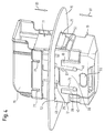
- the pre-assembled connector part is shown in FIGS. 2 and 3.
- the auxiliary unit 19 is here due to the latching of the test latch 61 and Locking step 65 on the associated receiving recess 47 against secured detachment from the securing unit 17.
- An unintentional Release the securing unit 17 from the base unit 11 against the Assembly direction 81 is due to the interaction of the lower locking lugs 27 with the associated locking bar 43 prevented.
- the fuse unit 17 is on an unintended at the time of pre-assembly further introduction into the base unit 11 by bumping the locking bars 43 prevented from the associated upper locking projection 25.
- the blocking detent stage 65 of the auxiliary unit 19 lies in the assembly direction 81 on the locking tab 31 of the base unit 11 (FIG. 3).
- the connector part preassembled in this way is in one of the assembly directions 81 opposite fastening direction 83 with the auxiliary unit 19 inserted into the opening 13 of the sheet metal receptacle 15 until the locking arms 21 first pushed back by the border of the opening 13 be and finally lock at the opening 13.
- the base unit 11 formed over the outline of the mounting opening 13 protruding cantilevers prevent further penetration of the Base unit 11 into the opening 13.
- the auxiliary unit 19 is with one hand on the two Handle recesses 55, 57 gripped.
- the handle recesses 55, 57 are pressed together, so that the locking tab 63 is raised and thus the Blocking catch level 65 from the assigned receiving recess 47 or is released from the locking tab 31.
- the locking tab is during the explained pushing movement 59 of the auxiliary unit 19 on its test latch 61 from the unlocking phase 33 applied to the release tab 29 and from the Receiving well 47 raised.
- the release tab 29 pushes So under the locking tab 59 and in the positive receiving recess 47.
- To prevent the test latch from snagging unintentionally 61 to reliably prevent the unlocking phase 33 lies the test latch 61 with pre-assembled connector part already on the receiving tongue 35 on.
- the auxiliary unit 19 can only be removed if the Security unit 17 has been completely inserted into the base unit 11 is and thus the locking hook 11, the locking arms 21 properly To block. Otherwise, the receiving recesses 47 are not completely from the assigned unlocking tab 29 or blocking tab 31 covered so that during the retraction of the auxiliary unit 19th the test latch 61 - or even additionally the blocking latch level 65 - again springs back into the associated receiving recess 47. With others Words is queried by removing the auxiliary unit 19 whether the security unit 17 the snap fastening of the base unit 11 as intended backs up.
- the units 11, 17, 19 encoded i.e. shaped so that a plug connection with each other only possible with a predetermined orientation relative to each other is.
- the longitudinal rib 73 of the auxiliary unit 19 is not mirror-symmetrical trained (Fig. 1c), so that an insertion of the auxiliary unit 19 in the coupling section 41 of the securing unit 17 only when it is correct Alignment is possible.
Landscapes
- Details Of Connecting Devices For Male And Female Coupling (AREA)
Abstract
Description
- Fig. 1a bis 1c
- eine Basiseinheit, eine Sicherungseinheit bzw. eine Hilfseinheit eines erfindungsgemäßen Verbinderteils in einer Explosionsdarstellung,
- Fig. 2 und 3
- das vormontierte Verbinderteil gemäß Fig. 1 in einer perspektivischen Vorderansicht bzw. Rückansicht, und
- Fig. 4
- das vormontierte und an einer Befestigungsöffnung befestigte Verbinderteil gemäß Fig. 1 sowie eine daran montierte Anschlußeinheit in einer perspektivischen Vorderansicht.
- 11
- Basiseinheit
- 13
- Befestigungsöffnung
- 15
- Blechaufnahme
- 17
- Sicherungseinheit
- 19
- Hilfseinheit
- 21
- Rastarm
- 22
- Anschlagabsatz
- 23
- Rastlasche
- 25
- oberer Rastansatz
- 27
- unterer Rastansatz
- 29
- Entriegelungslasche
- 31
- Blockierlasche
- 33
- Entriegelungsphase
- 35
- Aufnahmezunge
- 37
- Anschlagrippe
- 39
- Kontaktabschnitt
- 41
- Kupplungsabschnitt
- 43
- Rastleiste
- 45
- Führungszapfen
- 47
- Aufnahmevertiefung
- 49
- Führungsflügel
- 51
- Sicherungshaken
- 53
- Ringmantel
- 55
- Griffvertiefung
- 57
- Griffvertiefung
- 59
- Verriegelungslasche
- 61
- Prüfrastnase
- 63
- Blockierlasche
- 65
- Blockierraststufe
- 67
- Betätigungslasche
- 69
- Längsfortsatz
- 71
- Führungskanal
- 73
- Längsrippe
- 75
- Anschlußeinheit
- 77
- Befestigungsrastnase
- 79
- Befestigungsrastnase
- 81
- Montagerichtung
- 83
- Befestigungsrichtung
Claims (17)
- Elektrisches Verbinderteil zur Befestigung an einer Befestigungsstelle (13) insbesondere an einer Fahrzeugtür,mit einer Basiseinheit (11) und einer Sicherungseinheit (17), die für eine Vormontage des Verbinderteils miteinander sowie mit einer Hilfseinheit (19) verbindbar sind,
wobei eine Befestigungseinrichtung (21) vorgesehen ist zur Befestigung des vormontierten Verbinderteils an der Befestigungsstelle (13),
wobei ferner eine Prüfeinrichtung (61) vorgesehen ist, die bei vormontiertem und befestigtem Verbinderteil einen Sperrzustand einnimmt,
wobei ferner die Basiseinheit (11) und die Sicherungseinheit (17) des vormontierten Verbinderteils durch vorzugsweise axiale Bewegung der Hilfseinheit (19) dergestalt endmontierbar sind, daß die Befestigungseinrichtung (21) gesichert und die Prüfeinrichtung (61) freigegeben ist, und
wobei ferner die Hilfseinheit (19) von der endmontierten Einheit aus Basiseinheit (11) und Sicherungseinheit (17) lediglich bei freigegebener Prüfeinrichtung (61) lösbar ist. - Verbinderteil nach Anspruch 1,
wobei die Befestigungseinrichtung wenigstens einen, vorzugsweise zwei an der Basiseinheit (11) vorgesehene Rastarme (21) aufweist. - Verbinderteil nach einem der vorhergehenden Ansprüche,
wobei zur Sicherung der Befestigungseinrichtung (21) die Sicherungseinheit (17) wenigstens ein Sicherungselement (51) aufweist, das bei endmontiertem Verbinderteil die Befestigungseinrichtung (21) gegen eine Lösbewegung blockiert. - Verbinderteil nach einem der vorhergehenden Ansprüche,
wobei die Prüfeinrichtung wenigstens eine an der Hilfseinheit (19) ausgebildete Prüfnase (61) aufweist, die im Sperrzustand eine Ausnehmung (47) an der Sicherungseinheit (17) oder an der Basiseinheit (11) hintergreift. - Verbinderteil nach Anspruch 4,
wobei die Prüfeinrichtung ferner wenigstens einen an der Basiseinheit (11) oder an der Sicherungseinheit (17) ausgebildeten Zwangssteuerungsansatz (29, 33, 35) aufweist, durch den die Prüfnase (61) für ihre Freigabe aus der Ausnehmung (47) lösbar ist. - Verbinderteil nach einem der vorhergehenden Ansprüche,
wobei die Hilfseinheit (19) eine Blockiereinrichtung (31, 65) aufweist, durch die bei vormontiertem Verbinderteil eine Relativbewegung zwischen Einheiten des Verbinderteils, insbesondere eine Endmontagebewegung zwischen der Basiseinheit (11) und der Sicherungseinheit (17), blockierbar ist, und wobei die Hilfseinheit (19) ferner eine Betätigungseinrichtung (57, 67) aufweist, durch die zur Freigabe der Relativbewegung die Blockiereinrichtung (31, 65) wahlweise lösbar ist. - Verbinderteil nach Anspruch 6,
wobei die Blockiereinrichtung eine Blockierstufe (65) und die Betätigungseinrichtung einen mit der Blockierstufe (65) verbundenen Kipptaster (57, 67) aufweist. - Verbinderteil nach einem der vorhergehenden Ansprüche,
wobei zur Vormontage des Verbinderteils die Basiseinheit (11), die Sicherungseinheit (17) und die Hilfseinheit (19) entlang einer gemeinsamen Axialrichtung (81, 83) miteinander steckverbindbar sind. - Verbinderteil nach einem der vorhergehenden Ansprüche,
wobei wenigstens ein Rastelement (27, 43; 47, 61, 65) vorgesehen ist, durch das die Basiseinheit (11), die Sicherungseinheit (17) und die Hilfseinheit (19) bei der Vormontage des Verbinderteils miteinander verrastbar sind. - Verbinderteil nach einem der vorhergehenden Ansprüche,
wobei wenigstens ein weiteres Rastelement (25, 43) vorgesehen ist, durch das die Basiseinheit (11) und die Sicherungseinheit (17) bei der Endmontage des Verbinderteils miteinander verrastbar sind. - Verbinderteil nach einem der vorhergehenden Ansprüche,
wobei das Verbinderteil Anschlagelemente (37, 61, 65; 31, 65; 22, 51) aufweist zur Begrenzung einer maximalen Relativbewegung der Einheiten (11, 17, 19) zueinander. - Verbinderteil nach einem der vorhergehenden Ansprüche,
wobei das Verbinderteil insbesondere an der Sicherungseinheit (17) einen im wesentlichen rechteckigen Kupplungsabschnitt (41) zur Kupplung mit einem komplementären Verbinderteil aufweist. - Verfahren zur Montage und Befestigung eines elektrischen Verbinderteils an einer Befestigungsstelle (13) insbesondere an einer Fahrzeugtür,
wobei das Verbinderteil insbesondere nach einem der vorhergehenden Ansprüche ausgebildet ist,bei dem zur Vormontage des Verbinderteils eine Basiseinheit (11), eine Sicherungseinheit (17) und eine Hilfseinheit (19) derart miteinander verbunden werden, daß die Hilfseinheit (19) gegen ein Loslösen gesperrt wird,bei dem danach das vormontierte Verbinderteil an der Befestigungsstelle (13) befestigt wird,bei dem danach die Basiseinheit (11) und die Sicherungseinheit (17) durch eine vorzugsweise axiale Bewegung der Hilfseinheit (19) derart endmontiert werden, daß die Basiseinheit (11) gegen ein unbeabsichtigtes Lösen von der Befestigungsstelle (13) gesichert und die Sperrung der Hilfseinheit (19) freigegeben wird, undbei dem schließlich die Hilfseinheit (19) von der befestigten und endmontierten Einheit aus Basiseinheit (11) und Sicherungseinheit (17) gelöst wird. - Verfahren nach Anspruch 13,
wobei die Basiseinheit (11), die Sicherungseinheit (17) und die Hilfseinheit (19) durch Steckbewegungen entlang einer gemeinsamen Axialrichtung (81, 83) miteinander vormontiert werden. - Verfahren nach Anspruch 13 oder Anspruch 14,
wobei die Hilfseinheit (19) bei der Vormontage durch einen Sperreingriff einer Prüfeinrichtung (61) gesperrt und bei der Endmontage durch ein Aufheben des Sperreingriffs der Prüfeinrichtung (61) freigegeben wird. - Verfahren nach einem der Ansprüche 13 bis 15,
wobei vor der Bewegung der Hilfseinheit (19) bei der Endmontage eine Blockiereinrichtung (31, 65) gelöst wird, die bei vormontiertem Verbinderteil eine Relativbewegung zwischen Einheiten (11, 17) des Verbinderteils blockiert. - Verfahren nach einem der Ansprüche 13 bis 16,
wobei durch die Bewegung der Hilfseinheit (19) bei der Endmontage abgefragt wird, ob das Verbinderteil an der Befestigungsstelle (13) ordnungsgemäß befestigt ist.
Applications Claiming Priority (2)
| Application Number | Priority Date | Filing Date | Title |
|---|---|---|---|
| DE1999109740 DE19909740A1 (de) | 1999-03-05 | 1999-03-05 | Verbinderteil |
| DE19909740 | 1999-03-05 |
Publications (3)
| Publication Number | Publication Date |
|---|---|
| EP1035620A2 true EP1035620A2 (de) | 2000-09-13 |
| EP1035620A3 EP1035620A3 (de) | 2002-03-20 |
| EP1035620B1 EP1035620B1 (de) | 2006-07-05 |
Family
ID=7899839
Family Applications (1)
| Application Number | Title | Priority Date | Filing Date |
|---|---|---|---|
| EP20000103647 Expired - Lifetime EP1035620B1 (de) | 1999-03-05 | 2000-02-21 | Befestigung eines Verbinders |
Country Status (2)
| Country | Link |
|---|---|
| EP (1) | EP1035620B1 (de) |
| DE (2) | DE19909740A1 (de) |
Families Citing this family (1)
| Publication number | Priority date | Publication date | Assignee | Title |
|---|---|---|---|---|
| DE19932113B4 (de) * | 1999-07-09 | 2005-12-15 | Audi Ag | Elektrische Steckverbindung |
Family Cites Families (2)
| Publication number | Priority date | Publication date | Assignee | Title |
|---|---|---|---|---|
| JP2567945Y2 (ja) * | 1993-03-11 | 1998-04-08 | 住友電装株式会社 | パネル取付コネクタ用保護キャップ |
| DE19548543C1 (de) * | 1995-12-23 | 1997-06-12 | Delphi Automotive Systems Gmbh | Elektrische Steckverbindung, insbesondere für Kraftfahrzeuge |
-
1999
- 1999-03-05 DE DE1999109740 patent/DE19909740A1/de not_active Withdrawn
-
2000
- 2000-02-21 DE DE50013105T patent/DE50013105D1/de not_active Expired - Fee Related
- 2000-02-21 EP EP20000103647 patent/EP1035620B1/de not_active Expired - Lifetime
Also Published As
| Publication number | Publication date |
|---|---|
| DE50013105D1 (de) | 2006-08-17 |
| DE19909740A1 (de) | 2000-09-07 |
| EP1035620B1 (de) | 2006-07-05 |
| EP1035620A3 (de) | 2002-03-20 |
Similar Documents
| Publication | Publication Date | Title |
|---|---|---|
| DE10221862B4 (de) | Steckverbindung zur Verhinderung eines unvollständig verbundenen Zustands | |
| DE69737280T2 (de) | Gehäuse angepasst an ein Lagesicherungssystem für einen elektrischen Verbinder | |
| EP2957000B1 (de) | Elektrischer rundsteckverbinder mit push-pull-verriegelung | |
| DE69504217T2 (de) | Elektrischer Verbinder mit Lagesicherungsvorrichtung | |
| EP1449280B1 (de) | Steckverbinder mit während des steckvorgangs verrastender sekundärverriegelung | |
| DE3840249C2 (de) | ||
| EP1766165B1 (de) | Vorrichtung zur betätigung eines in einer tür, einer klappe od. dgl. eingebauten schlosses, insbesondere bei einem fahrzeug | |
| DE102008035193A1 (de) | Kontrollierbare Steckverbindung und Verfahren zur Kontrolle des Steckzustandes einer Steckverbindung | |
| EP1662620A2 (de) | Elektrische Steckverbindung | |
| WO2007016794A1 (de) | Sicherungsvorrichtung für einen stecker (patch guard) | |
| EP3679631B1 (de) | Steckverbinder mit verriegelungshaken zur festlegung seines kontaktträgers in seinem aussengehäuse | |
| DE10164856B4 (de) | Steckverbinder mit einem Verriegelungssicherungsmechanismus | |
| DE19840726C2 (de) | Elektrischer Steckverbinder | |
| DE69806239T2 (de) | Verbinder mit sekondärverriegelung und kupplungsvorrichtung | |
| DE10259067B4 (de) | Verbinder und Verfahren zum Montieren eines Verbindergehäuses an einer Platte | |
| DE102016104303A1 (de) | Sekundärverriegelungsmittel zum Verhindern des Lösens einer Primärverriegelung eines elektrischen Steckverbinders sowie Verriegelungsanordnung aus zwei Sekundärverriegelungsmitteln | |
| DE102011002135B4 (de) | Steckerelement mit zweiter Kontaktsicherung | |
| EP0984524B1 (de) | Zweiteiliger elektrischer Steckverbinder mit einem Koppelteil und einem bewegbaren Kontrollelement | |
| EP1513225B1 (de) | Verriegelungselement für eine Steckverbindung | |
| DE602004011987T2 (de) | Kontaktverrieglungseinrichtung für einen elektrischen Verbinder und die Einrichtung enthaltender elektrischer Verbinder | |
| DE102016121847B4 (de) | Steckverbinderteil und Verfahren zum Montieren eines Steckverbinderteils | |
| DE10304847B4 (de) | Verbinder | |
| DE60006331T2 (de) | Steckvorrichtungssystem zur Verhinderung einer falschen Kupplung | |
| DE102023128664B3 (de) | Ladesteckerhalter für eine Ladevorrichtung zum Laden von Elektrofahrzeugen, und Ladevorrichtung | |
| DE69622082T2 (de) | Verbindungsmodul mit abnehmbaren Kontakten und Anwendung in Verbindungsleisten |
Legal Events
| Date | Code | Title | Description |
|---|---|---|---|
| PUAI | Public reference made under article 153(3) epc to a published international application that has entered the european phase |
Free format text: ORIGINAL CODE: 0009012 |
|
| AK | Designated contracting states |
Kind code of ref document: A2 Designated state(s): DE ES FR GB IT Kind code of ref document: A2 Designated state(s): AT BE CH CY DE DK ES FI FR GB GR IE IT LI LU MC NL PT SE |
|
| AX | Request for extension of the european patent |
Free format text: AL;LT;LV;MK;RO;SI |
|
| PUAL | Search report despatched |
Free format text: ORIGINAL CODE: 0009013 |
|
| AK | Designated contracting states |
Kind code of ref document: A3 Designated state(s): AT BE CH CY DE DK ES FI FR GB GR IE IT LI LU MC NL PT SE |
|
| AX | Request for extension of the european patent |
Free format text: AL;LT;LV;MK;RO;SI |
|
| RIC1 | Information provided on ipc code assigned before grant |
Free format text: 7H 01R 13/74 A, 7H 01R 13/506 B |
|
| 17P | Request for examination filed |
Effective date: 20020506 |
|
| AKX | Designation fees paid |
Free format text: DE ES FR GB IT |
|
| GRAP | Despatch of communication of intention to grant a patent |
Free format text: ORIGINAL CODE: EPIDOSNIGR1 |
|
| GRAS | Grant fee paid |
Free format text: ORIGINAL CODE: EPIDOSNIGR3 |
|
| GRAA | (expected) grant |
Free format text: ORIGINAL CODE: 0009210 |
|
| AK | Designated contracting states |
Kind code of ref document: B1 Designated state(s): DE ES FR GB IT |
|
| PG25 | Lapsed in a contracting state [announced via postgrant information from national office to epo] |
Ref country code: IT Free format text: LAPSE BECAUSE OF FAILURE TO SUBMIT A TRANSLATION OF THE DESCRIPTION OR TO PAY THE FEE WITHIN THE PRESCRIBED TIME-LIMIT;WARNING: LAPSES OF ITALIAN PATENTS WITH EFFECTIVE DATE BEFORE 2007 MAY HAVE OCCURRED AT ANY TIME BEFORE 2007. THE CORRECT EFFECTIVE DATE MAY BE DIFFERENT FROM THE ONE RECORDED. Effective date: 20060705 Ref country code: GB Free format text: LAPSE BECAUSE OF FAILURE TO SUBMIT A TRANSLATION OF THE DESCRIPTION OR TO PAY THE FEE WITHIN THE PRESCRIBED TIME-LIMIT Effective date: 20060705 |
|
| REG | Reference to a national code |
Ref country code: GB Ref legal event code: FG4D Free format text: NOT ENGLISH |
|
| REF | Corresponds to: |
Ref document number: 50013105 Country of ref document: DE Date of ref document: 20060817 Kind code of ref document: P |
|
| PG25 | Lapsed in a contracting state [announced via postgrant information from national office to epo] |
Ref country code: ES Free format text: LAPSE BECAUSE OF FAILURE TO SUBMIT A TRANSLATION OF THE DESCRIPTION OR TO PAY THE FEE WITHIN THE PRESCRIBED TIME-LIMIT Effective date: 20061016 |
|
| ET | Fr: translation filed | ||
| GBV | Gb: ep patent (uk) treated as always having been void in accordance with gb section 77(7)/1977 [no translation filed] |
Effective date: 20060705 |
|
| PLBE | No opposition filed within time limit |
Free format text: ORIGINAL CODE: 0009261 |
|
| STAA | Information on the status of an ep patent application or granted ep patent |
Free format text: STATUS: NO OPPOSITION FILED WITHIN TIME LIMIT |
|
| 26N | No opposition filed |
Effective date: 20070410 |
|
| PGFP | Annual fee paid to national office [announced via postgrant information from national office to epo] |
Ref country code: DE Payment date: 20090219 Year of fee payment: 10 |
|
| PGFP | Annual fee paid to national office [announced via postgrant information from national office to epo] |
Ref country code: IT Payment date: 20090213 Year of fee payment: 10 |
|
| PGFP | Annual fee paid to national office [announced via postgrant information from national office to epo] |
Ref country code: FR Payment date: 20090213 Year of fee payment: 10 |
|
| REG | Reference to a national code |
Ref country code: FR Ref legal event code: ST Effective date: 20101029 |
|
| PG25 | Lapsed in a contracting state [announced via postgrant information from national office to epo] |
Ref country code: FR Free format text: LAPSE BECAUSE OF NON-PAYMENT OF DUE FEES Effective date: 20100301 |
|
| PG25 | Lapsed in a contracting state [announced via postgrant information from national office to epo] |
Ref country code: DE Free format text: LAPSE BECAUSE OF NON-PAYMENT OF DUE FEES Effective date: 20100901 |
|
| PG25 | Lapsed in a contracting state [announced via postgrant information from national office to epo] |
Ref country code: IT Free format text: LAPSE BECAUSE OF NON-PAYMENT OF DUE FEES Effective date: 20100221 |