EP1031815B1 - Capteur de vitesse angulaire - Google Patents
Capteur de vitesse angulaire Download PDFInfo
- Publication number
- EP1031815B1 EP1031815B1 EP99943348A EP99943348A EP1031815B1 EP 1031815 B1 EP1031815 B1 EP 1031815B1 EP 99943348 A EP99943348 A EP 99943348A EP 99943348 A EP99943348 A EP 99943348A EP 1031815 B1 EP1031815 B1 EP 1031815B1
- Authority
- EP
- European Patent Office
- Prior art keywords
- amplifier
- output
- voltage
- output signal
- angular rate
- Prior art date
- Legal status (The legal status is an assumption and is not a legal conclusion. Google has not performed a legal analysis and makes no representation as to the accuracy of the status listed.)
- Expired - Lifetime
Links
Images

Classifications
-
- G—PHYSICS
- G01—MEASURING; TESTING
- G01C—MEASURING DISTANCES, LEVELS OR BEARINGS; SURVEYING; NAVIGATION; GYROSCOPIC INSTRUMENTS; PHOTOGRAMMETRY OR VIDEOGRAMMETRY
- G01C19/00—Gyroscopes; Turn-sensitive devices using vibrating masses; Turn-sensitive devices without moving masses; Measuring angular rate using gyroscopic effects
- G01C19/56—Turn-sensitive devices using vibrating masses, e.g. vibratory angular rate sensors based on Coriolis forces
- G01C19/5607—Turn-sensitive devices using vibrating masses, e.g. vibratory angular rate sensors based on Coriolis forces using vibrating tuning forks
Definitions
- the present invention relates to an angular rate sensor.
- This angular rate sensor comprises an exciting unit for providing a tuning fork vibrator with vibration, a means for detecting a vibration level of the vibrator, a detection means for detecting Coriolis' force generated responsive to an angular rate, a first amplifier for amplifying an output signal of the means for detecting vibration level, a rectifier circuit for rectifying an output signal of the first amplifier to obtain a DC voltage, a comparator of an output voltage of the rectifier circuit with a reference voltage, and a variable gain amplifier connected to the exciting unit in a manner that a vibrating amplitude of the tuning fork vibrator is controlled to be constant by varying an amplification factor for amplifying a voltage, which is produced by shifting a phase of an output voltage of the first amplifier by 90 degrees, according to an output voltage of the comparator.
- variable gain amplifier operates in a manner to rapidly increase a vibrating amplitude of the tuning fork vibrator, since the amplification factor of the variable gain amplifier becomes the maximum within a predetermined degree immediately after a power supply is turned on.
- a variable range of the amplification factor of the variable gain amplifier is limited and it can not be boosted so much, it has needed a fairly long time for the tuning fork vibrator before a level of its vibrating amplitude reaches a predetermined degree.
- the maximum level of amplification factor of the variable gain amplifier is set greater than the predetermined degree, it is difficult to increase the maximum level of amplification factor of the variable gain amplifier beyond the predetermined degree from an overall aspect including a problem of saturation in waveform of an output voltage of the variable gain amplifier, maintaining noise low, and stability in controlling a vibrating amplitude of the tuning fork vibrator constant.
- the present invention is intended to solve the above-mentioned problem of the prior art, and it aims at providing an angular rate sensor that is capable of realizing a reduction of a start-up time.
- the present invention is characterized by having an exciting unit for providing a vibrator with vibration, a means for detecting a vibration level of the vibrator, a detection means for detecting Coriolis' force generated responsive to an angular rate, a first amplifier for amplifying an output signal of the means of detecting vibration level, a rectifier circuit for rectifying an output signal of the first amplifier to obtain a DC voltage, a variable gain amplifier for taking as an input the output signal of the first amplifier and for varying an amplification factor according to an output voltage of the rectifier circuit, a second amplifier for amplifying an output signal of the variable gain amplifier, a level judgement circuit in which the output voltage of the rectifier circuit and an output voltage of a reference voltage generator are input, and a third amplifier and a switching means placed between the first amplifier and the second amplifier, wherein the output signal of the first amplifier is input to a positive input terminal of the third amplifier, a first resistor is inserted between a negative input terminal of the third amplifier and an output terminal of the third
- a structure as described above is able to realize a reduction of the start-up time of the angular rate sensor, while clearing entirely the general matters such as a problem of saturation in waveform of an output voltage of the variable gain amplifier, maintaining noise low, and stability in controlling a vibrating amplitude of the tuning fork vibrator constant. It is especially effective in such case as a crystal tuning fork vibrator having a large degree of sharpness "Q".
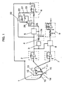
- Fig. 1 is a block diagram of an angular rate sensor of an exemplary embodiment of the present invention.
- a numeral 1 is a vibration type angular rate sensor element block having a tuning fork structure
- a numeral 2 is a first amplifier
- a numeral 3 is a rectifier
- a numeral 4 is a smoothing circuit
- a numeral 5 is a variable gain amplifier
- a numeral 6 is a second amplifier
- a numeral 7 is a fourth amplifier
- a numeral 8 is a synchronous detector
- a numeral 9 is a low-pass filter.
- a reference numeral 10 designates an exciting unit composed of a piezo-electric element attached to a vibrating member
- a numeral 11 is a means composed of another piezo-electric element attached to a vibrating member for detecting a vibration level
- numerals 12 and 13 are first and second detection means for detecting Coriolis' force generated responsive to an angular rate.
- the exciting unit 10 and the first detection means 12 are bonded together orthogonally to each other, the means 11 of detecting vibration level and the second detection means 13 are also bonded orthogonally to each other, and these are connected by a connecting plate 14.
- the vibration type angular rate sensor element block 1 having a tuning fork structure is thus constructed by supporting the connecting plate 14 at one point with a supporting post 15.
- the means 11 for detecting a vibration level of tuning-fork vibration caused by oscillation of the exciting unit 10 the first amplifier 2 for amplifying an output signal of the means 11 of detecting vibration level as its input signal, the rectifier 3 for rectifying an output signal of the first amplifier 2, the smoothing circuit 4 for smoothing an output voltage of the rectifier 3, the variable gain amplifier 5 whose amplification factor for amplifying an output voltage of the first amplifier 2 varies responsive to a magnitude of an output voltage of the smoothing circuit 4, thereby controlling a vibrating amplitude of the tuning fork vibrator constant, and the second amplifier 6 for amplifying an output signal of the variable gain amplifier.
- Signals of the first and the second detection means 12 and 13 for detecting Coriolis' force generated responsive to an impressed angular rate are amplified by the fourth amplifier 7, detected by the synchronous detector 8 at a vibrating cycle of the tuning fork vibrator to become a voltage proportional to the angular rate, and it is output as an angular rate voltage signal after amplified by the low pass filter 9.
- a reference numeral 20 designates a third amplifier, numeral 21 a capacitor, numeral 22 a first resistor, numeral 23 a second resistor, numeral 24 a capacitor, numeral 25 a reference voltage generator, numeral 26 a level judgment circuit, and numeral 27 a switching means.
- the level judgment circuit 26 in which the output voltage of the smoothing circuit 4 and an output voltage of the reference voltage generator 25 are input, and the third amplifier 20 and the switching means 27 between the first amplifier 2 and the second amplifier 6.
- a negative input terminal of the third amplifier 20 is connected with a voltage having 1/2 of a power supply voltage Vcc through the capacitor 21.
- an output signal of the first amplifier 2 is input to a positive input terminal of the third amplifier 20, the first resistor 22 is inserted between the negative input terminal of the third amplifier 20 and an output terminal of the third amplifier 20, and the second resistor 23 and the switching means 27 are connected in series between the output terminal of the third amplifier 20 and an input terminal of the second amplifier 6.
- the first resistor 22 and the second resistor 23 are 1M ⁇ and 20k ⁇ respectively, and the switching means 27 is turned on and off according to a potential of voltage charged in the capacitor 24, the level judgment circuit 26 (a voltage potential set by the reference voltage generator 25 is denoted as V1), and the timing chart for switching control shown in Fig. 2 , after a power supply (not shown) is turned on.
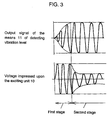
- the third amplifier 20 operates for an output waveform between the power supply voltage and the grounding voltage with the reference voltage (1/2 of the power supply voltage Vcc) at the median, and that the third amplifier 20 goes on and off respectively in a first stage and a second stage shown in the timing chart (refer to Fig. 2 ).
- an output voltage in the second amplifier 6 can be made very large (a voltage impressed upon the exciting unit 10 becomes maximum of the output voltage from the start) during an initial stage when a vibrating amplitude of the tuning fork vibrator is small (i.e.
- the vibrator needs not be limited only to the vibration type having the conventional tuning fork structure.
- an angular rate sensor which not only has a function of arbitrarily setting a time for vibrating amplitude of a vibrator to become constant, but also is capable of substantially reducing a start-up time while clearing entirely the general matters such as a problem of saturation in waveform of an output voltage of a variable gain amplifier, maintaining noise low, and stability in controlling the vibrating amplitude of the vibrator constant, since it can maximize an output voltage of a second amplifier by a third amplifier and a switching means upon a start-up, and maintain the maximum level of amplification factor of the variable gain amplifier at a predetermined level as in the past at least after having entered into a final control stage.
Landscapes
- Physics & Mathematics (AREA)
- Engineering & Computer Science (AREA)
- General Physics & Mathematics (AREA)
- Radar, Positioning & Navigation (AREA)
- Remote Sensing (AREA)
- Gyroscopes (AREA)
- Transmission And Conversion Of Sensor Element Output (AREA)
Abstract
Claims (1)
- Capteur de vitesse angulaire (1) comprenant :une unité d'excitation (10) pour procurer une vibration à un dispositif de vibration;un moyen (11) pour détecter un niveau de vibration dudit dispositif de vibration;un moyen de détection (12, 13) pour détecter une force de Coriolis générée en réponse à une vitesse angulaire;un premier amplificateur (2) pour amplifier un signal de sortie dudit moyen (11) de détection d'un niveau de vibration;un circuit redresseur (3) pour redresser un signal de sortie dudit premier amplificateur (2) pour obtenir une tension électrique de courant continu;un amplificateur à gain variable (5) pour prendre comme une entrée le signal de sortie dudit premier amplificateur (2), où un facteur d'amplification varie selon une tension électrique de sortie dudit circuit redresseur (3);un deuxième amplificateur (6) pour amplifier un signal de sortie dudit amplificateur à gain variable (5);un circuit de jugement de niveau (26) dans lequel la tension électrique de sortie dudit circuit redresseur (3) et une tension électrique de sortie d'un générateur de tension électrique de référence (25) sont entrées; etun troisième amplificateur (20) et un moyen de commutation (27) placés entre ledit premier amplificateur (2) et ledit deuxième amplificateur (6),où ledit capteur de vitesse angulaire est construit d'une manière telle que:le signal de sortie dudit premier amplificateur (2) est entré à une borne d'entrée positive dudit troisième amplificateur (20);une première résistance (22) est insérée entre une borne d'entrée négative dudit troisième amplificateur (20) et une borne de sortie dudit troisième amplificateur (20);une tension électrique ayant un potentiel proche de 1/2 d'une tension électrique d'alimentation de puissance (Vcc) est imposée sur la borne d'entrée négative dudit troisième amplificateur (20) à travers un condensateur (21),une deuxième résistance (23) et ledit moyen de commutation (27) sont connectés en série entre la borne de sortie dudit troisième amplificateur (20) et une borne d'entrée dudit deuxième amplificateur (6); etledit moyen de commutation (27) est activé par une sortie dudit circuit de jugement de niveau (26).
Applications Claiming Priority (3)
| Application Number | Priority Date | Filing Date | Title |
|---|---|---|---|
| JP26114498 | 1998-09-16 | ||
| JP26114498A JP4075152B2 (ja) | 1998-09-16 | 1998-09-16 | 角速度センサ |
| PCT/JP1999/005029 WO2000016043A1 (fr) | 1998-09-16 | 1999-09-14 | Capteur de vitesse angulaire |
Publications (3)
| Publication Number | Publication Date |
|---|---|
| EP1031815A1 EP1031815A1 (fr) | 2000-08-30 |
| EP1031815A4 EP1031815A4 (fr) | 2000-11-29 |
| EP1031815B1 true EP1031815B1 (fr) | 2008-03-12 |
Family
ID=17357720
Family Applications (1)
| Application Number | Title | Priority Date | Filing Date |
|---|---|---|---|
| EP99943348A Expired - Lifetime EP1031815B1 (fr) | 1998-09-16 | 1999-09-14 | Capteur de vitesse angulaire |
Country Status (5)
| Country | Link |
|---|---|
| US (1) | US6412347B1 (fr) |
| EP (1) | EP1031815B1 (fr) |
| JP (1) | JP4075152B2 (fr) |
| DE (1) | DE69938333T2 (fr) |
| WO (1) | WO2000016043A1 (fr) |
Families Citing this family (13)
| Publication number | Priority date | Publication date | Assignee | Title |
|---|---|---|---|---|
| US6792802B2 (en) * | 2002-03-07 | 2004-09-21 | Honeywell International Inc. | Noise source for starting MEMS gyroscope |
| US6972619B2 (en) * | 2002-12-17 | 2005-12-06 | Matsushita Electric Industrial Co., Ltd. | Amplifier with a gain proportional to power source voltage |
| JP4529444B2 (ja) * | 2004-01-13 | 2010-08-25 | パナソニック株式会社 | 角速度センサ |
| JP2005227214A (ja) * | 2004-02-16 | 2005-08-25 | Matsushita Electric Ind Co Ltd | 角速度センサ及びそれを用いた自動車 |
| CN100368773C (zh) * | 2004-06-29 | 2008-02-13 | 东南大学 | 电容式微陀螺敏感信号的单路谐波提取方法及提取装置 |
| CN100368772C (zh) * | 2004-06-29 | 2008-02-13 | 东南大学 | 电容式微陀螺敏感信号的双路谐波提取方法及提取装置 |
| JP2006349409A (ja) * | 2005-06-14 | 2006-12-28 | Denso Corp | 静電駆動・容量検出型のジャイロセンサのセンサ回路 |
| JP4696996B2 (ja) * | 2006-03-27 | 2011-06-08 | パナソニック株式会社 | 慣性力センサ |
| JP5034808B2 (ja) * | 2006-10-17 | 2012-09-26 | セイコーエプソン株式会社 | 駆動装置、物理量測定装置及び電子機器 |
| JP5136016B2 (ja) * | 2006-11-27 | 2013-02-06 | セイコーエプソン株式会社 | 駆動装置、物理量測定装置及び電子機器 |
| JP4450029B2 (ja) * | 2007-07-24 | 2010-04-14 | セイコーエプソン株式会社 | 発振駆動回路、発振駆動装置、物理量測定回路、物理量測定装置および電子機器 |
| FR2937413B1 (fr) * | 2008-10-22 | 2010-11-26 | Sagem Defense Securite | Procede de commande d'un capteur a resonateur vibrant a demarrage rapide |
| JP5625916B2 (ja) | 2009-02-13 | 2014-11-19 | パナソニック株式会社 | 発振回路、発振回路の製造方法、この発振回路を用いた慣性センサ及び電子機器 |
Family Cites Families (4)
| Publication number | Priority date | Publication date | Assignee | Title |
|---|---|---|---|---|
| JPH0348714A (ja) | 1989-07-18 | 1991-03-01 | Matsushita Electric Ind Co Ltd | 角速度センサ駆動回路 |
| US5041802A (en) * | 1989-10-11 | 1991-08-20 | Zilog, Inc. | Low power oscillator with high start-up ability |
| JPH0933262A (ja) * | 1995-07-25 | 1997-02-07 | Nikon Corp | 励振駆動回路及び方法並びにこれを用いた圧電振動角速度計 |
| JP3932661B2 (ja) * | 1998-03-31 | 2007-06-20 | 松下電器産業株式会社 | 角速度センサ駆動回路 |
-
1998
- 1998-09-16 JP JP26114498A patent/JP4075152B2/ja not_active Expired - Fee Related
-
1999
- 1999-09-14 US US09/554,522 patent/US6412347B1/en not_active Expired - Fee Related
- 1999-09-14 EP EP99943348A patent/EP1031815B1/fr not_active Expired - Lifetime
- 1999-09-14 WO PCT/JP1999/005029 patent/WO2000016043A1/fr active IP Right Grant
- 1999-09-14 DE DE69938333T patent/DE69938333T2/de not_active Expired - Lifetime
Also Published As
| Publication number | Publication date |
|---|---|
| EP1031815A1 (fr) | 2000-08-30 |
| US6412347B1 (en) | 2002-07-02 |
| JP2000088581A (ja) | 2000-03-31 |
| EP1031815A4 (fr) | 2000-11-29 |
| WO2000016043A1 (fr) | 2000-03-23 |
| DE69938333D1 (de) | 2008-04-24 |
| DE69938333T2 (de) | 2009-05-14 |
| JP4075152B2 (ja) | 2008-04-16 |
Similar Documents
| Publication | Publication Date | Title |
|---|---|---|
| EP0947803B1 (fr) | Circuit de commande pour capteur de vitesse angulaire | |
| EP1031815B1 (fr) | Capteur de vitesse angulaire | |
| US4277758A (en) | Ultrasonic wave generating apparatus with voltage-controlled filter | |
| EP1460380B1 (fr) | Procédé et système d'excitation d'une oscillation d'un vibrateur | |
| US4056761A (en) | Sonic transducer and drive circuit | |
| US8015874B2 (en) | Inertia force sensor | |
| US5912542A (en) | Variable load inductance compensation for motor drive circuits | |
| JPH0628230Y2 (ja) | 超音波振動子の振動制御装置 | |
| CA2203849A1 (fr) | Gyroscope vibratoire | |
| US6345533B1 (en) | Angular rate sensor | |
| JP2703410B2 (ja) | 電圧コンバータ回路 | |
| JP3190525B2 (ja) | 電動パワーステアリング装置 | |
| JPS6325911Y2 (fr) | ||
| JP2958962B2 (ja) | Pwmパルス発生装置 | |
| JPH0516272B2 (fr) | ||
| JP3495810B2 (ja) | 振動波モーター装置 | |
| JPH03112378A (ja) | 超音波モータの駆動回路 | |
| JPH02197273A (ja) | 超音波モータ駆動装置 | |
| JPH06177646A (ja) | 水晶発振回路 | |
| JPH0513554B2 (fr) | ||
| JPH0432623Y2 (fr) | ||
| JPH03112379A (ja) | 超音波モータの駆動回路 | |
| JPH0236777A (ja) | 超音波モーターの駆動装置 | |
| JPH06101940B2 (ja) | 超音波モ−タ− | |
| JPS6238882B2 (fr) |
Legal Events
| Date | Code | Title | Description |
|---|---|---|---|
| PUAI | Public reference made under article 153(3) epc to a published international application that has entered the european phase |
Free format text: ORIGINAL CODE: 0009012 |
|
| 17P | Request for examination filed |
Effective date: 20000515 |
|
| AK | Designated contracting states |
Kind code of ref document: A1 Designated state(s): AT BE CH CY DE DK ES FI FR GB GR IE IT LI LU MC NL PT SE |
|
| RAP1 | Party data changed (applicant data changed or rights of an application transferred) |
Owner name: MATSUSHITA ELECTRIC INDUSTRIAL CO., LTD. |
|
| A4 | Supplementary search report drawn up and despatched |
Effective date: 20001012 |
|
| AK | Designated contracting states |
Kind code of ref document: A4 Designated state(s): AT BE CH CY DE DK ES FI FR GB GR IE IT LI LU MC NL PT SE |
|
| RBV | Designated contracting states (corrected) |
Designated state(s): DE FR GB IT SE |
|
| GRAP | Despatch of communication of intention to grant a patent |
Free format text: ORIGINAL CODE: EPIDOSNIGR1 |
|
| GRAS | Grant fee paid |
Free format text: ORIGINAL CODE: EPIDOSNIGR3 |
|
| GRAA | (expected) grant |
Free format text: ORIGINAL CODE: 0009210 |
|
| AK | Designated contracting states |
Kind code of ref document: B1 Designated state(s): DE FR GB IT SE |
|
| REG | Reference to a national code |
Ref country code: GB Ref legal event code: FG4D |
|
| REF | Corresponds to: |
Ref document number: 69938333 Country of ref document: DE Date of ref document: 20080424 Kind code of ref document: P |
|
| REG | Reference to a national code |
Ref country code: SE Ref legal event code: TRGR |
|
| ET | Fr: translation filed | ||
| RAP2 | Party data changed (patent owner data changed or rights of a patent transferred) |
Owner name: PANASONIC CORPORATION |
|
| PLBE | No opposition filed within time limit |
Free format text: ORIGINAL CODE: 0009261 |
|
| STAA | Information on the status of an ep patent application or granted ep patent |
Free format text: STATUS: NO OPPOSITION FILED WITHIN TIME LIMIT |
|
| 26N | No opposition filed |
Effective date: 20081215 |
|
| REG | Reference to a national code |
Ref country code: GB Ref legal event code: 746 Effective date: 20091221 |
|
| PGFP | Annual fee paid to national office [announced via postgrant information from national office to epo] |
Ref country code: GB Payment date: 20120912 Year of fee payment: 14 Ref country code: SE Payment date: 20120911 Year of fee payment: 14 |
|
| PGFP | Annual fee paid to national office [announced via postgrant information from national office to epo] |
Ref country code: IT Payment date: 20120915 Year of fee payment: 14 Ref country code: DE Payment date: 20120912 Year of fee payment: 14 Ref country code: FR Payment date: 20120926 Year of fee payment: 14 |
|
| REG | Reference to a national code |
Ref country code: SE Ref legal event code: EUG |
|
| PG25 | Lapsed in a contracting state [announced via postgrant information from national office to epo] |
Ref country code: SE Free format text: LAPSE BECAUSE OF NON-PAYMENT OF DUE FEES Effective date: 20130915 |
|
| GBPC | Gb: european patent ceased through non-payment of renewal fee |
Effective date: 20130914 |
|
| REG | Reference to a national code |
Ref country code: DE Ref legal event code: R119 Ref document number: 69938333 Country of ref document: DE Effective date: 20140401 |
|
| REG | Reference to a national code |
Ref country code: FR Ref legal event code: ST Effective date: 20140530 |
|
| PG25 | Lapsed in a contracting state [announced via postgrant information from national office to epo] |
Ref country code: GB Free format text: LAPSE BECAUSE OF NON-PAYMENT OF DUE FEES Effective date: 20130914 |
|
| PG25 | Lapsed in a contracting state [announced via postgrant information from national office to epo] |
Ref country code: IT Free format text: LAPSE BECAUSE OF NON-PAYMENT OF DUE FEES Effective date: 20130914 Ref country code: DE Free format text: LAPSE BECAUSE OF NON-PAYMENT OF DUE FEES Effective date: 20140401 Ref country code: FR Free format text: LAPSE BECAUSE OF NON-PAYMENT OF DUE FEES Effective date: 20130930 |