EP1031679B1 - Parkvorrichtung für Fahrräder - Google Patents
Parkvorrichtung für Fahrräder Download PDFInfo
- Publication number
- EP1031679B1 EP1031679B1 EP00200634A EP00200634A EP1031679B1 EP 1031679 B1 EP1031679 B1 EP 1031679B1 EP 00200634 A EP00200634 A EP 00200634A EP 00200634 A EP00200634 A EP 00200634A EP 1031679 B1 EP1031679 B1 EP 1031679B1
- Authority
- EP
- European Patent Office
- Prior art keywords
- bicycle
- parking
- wheel
- wheels
- parking device
- Prior art date
- Legal status (The legal status is an assumption and is not a legal conclusion. Google has not performed a legal analysis and makes no representation as to the accuracy of the status listed.)
- Expired - Lifetime
Links
- 238000001514 detection method Methods 0.000 claims description 6
- 238000010276 construction Methods 0.000 description 2
- 230000000694 effects Effects 0.000 description 2
- 230000005484 gravity Effects 0.000 description 2
- XLYOFNOQVPJJNP-UHFFFAOYSA-N water Substances O XLYOFNOQVPJJNP-UHFFFAOYSA-N 0.000 description 2
- 230000002411 adverse Effects 0.000 description 1
- 230000005540 biological transmission Effects 0.000 description 1
- 239000003673 groundwater Substances 0.000 description 1
- 238000012423 maintenance Methods 0.000 description 1
- 238000012544 monitoring process Methods 0.000 description 1
- 238000005192 partition Methods 0.000 description 1
Images

Classifications
-
- E—FIXED CONSTRUCTIONS
- E04—BUILDING
- E04H—BUILDINGS OR LIKE STRUCTURES FOR PARTICULAR PURPOSES; SWIMMING OR SPLASH BATHS OR POOLS; MASTS; FENCING; TENTS OR CANOPIES, IN GENERAL
- E04H6/00—Buildings for parking cars, rolling-stock, aircraft, vessels or like vehicles, e.g. garages
- E04H6/005—Garages for vehicles on two wheels
Definitions
- the invention relates to a device for parking bicycles, according to the preamble of claim 1.
- Devices for parking bicycles are generally known and are used for parking bicycles at, for example, train and underground stations, apartment buildings, schools, office buildings and other public areas.
- DE-C-4 237 042 discloses a bicycle shed with a rotary cross which can rotate about a horizontal axis.
- the rotary cross has four bicycle parking elements, which are oriented perpendicular with respect to the axis and are in the form of elongate channels in which the bicycles can be secured by means of clamps, which lock their wheels.
- the bicycles, which have been placed in the bicycle shed are oriented in the longitudinal direction with the front wheels towards the axis of rotation.
- the rotary cross is partially positioned below ground level, in order to provide simple access to the bicycle parking locations.
- DE-A-195 45 816 discloses a different bicycle shed with a cylindrical drum which can rotate about a horizontal axis of rotation.
- the drum has a plurality of bicycle parking elements which are designed in such a manner that the longitudinal axis of the bicycles which have been placed in the bicycle shed is arranged substantially in the circumferential direction of the drum.
- a plurality of drums can be arranged coaxially one behind the other in order to increase the capacity of the bicycle shed.
- the drum is positioned partially below ground level.
- WO 84/02895 discloses a storage structure suitable to store bicycles.
- the object of the present invention is first to provide a device for parking bicycles which provides a high parking capacity in relation to a small ground surface required.
- a further purpose is to provide a parking device in which the bicycles can be parked safe and without the risk of damage to the bicycles.
- the invention achieves the first mentioned object by providing a bicycle parking device according to claim 1.
- This arrangement results in a highly advantageous utilization of the ground surface which is required for the bicycle shed, in contrast to the known bicycle sheds.
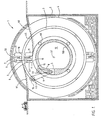
- Fig. 1 shows a device 1 for parking bicycles 50, which comprises an inner wheel 3 and an outer wheel 4, which in this case are arranged in a housing 2.
- the wheels 3, 4 can rotate about a common, substantially horizontal axis of rotation 51.
- the wheels 3, 4 are arranged concentrically with respect to one another and can rotate in both directions independently of one another.
- the concentric arrangement makes optimum use of the space which the wheels 3, 4 take up. The fact that they can rotate independently of one another contributes to rapid access to the bicycles 50 which are parked in the wheels 3, 4.
- Each wheel 3, 4 is provided around its circumference with a plurality of bicycle parking elements 6, 7, which are each designed to accommodate a single bicycle 50.
- the parking elements 6, 7 are substantially elongate, corresponding to the shape of a bicycle, and are arranged in such a manner that the longitudinal axis of a bicycle parking element 6, 7 is oriented substantially parallel to the axis of rotation 51. Consequently, a large number of bicycles 50 can be positioned closely adjacent to one another in a wheel 3, 4, with minimal space between the bicycles.
- the outer wheel 4 has 60 bicycle parking elements and the inner wheel 3 has 40 bicycle parking elements.
- the outer wheel can have a diameter of about 9 metres and the inner wheel can have a diameter of about 6 metres.
- the device 1 has an access ramp 60, 61 in order to reach the bicycle parking elements 6, 7.
- Each bicycle parking element 6, 7 forms an elongate space for accommodating a single bicycle and is at least partially delimited by a base surface 10 and side walls 11. Furthermore, in this example each bicycle parking element has an open front side and, opposite this side, a rear wall, as well as a ceiling opposite the base. In the design shown, the base surface 10 is directed towards the axis of rotation 51 and the side walls 11 are directed outwards from the base 10.
- the side walls 11 of adjacent bicycle parking elements 6, 7 may also comprise one common wall and serve substantially to prevent unauthorized access to an adjacent bicycle parking element 6, 7.
- the bicycle parking elements 6, 7 are rigidly connected to the corresponding wheel 3, 4, with the result that the bicycle parking elements 6, 7 maintain the same orientation with respect to the wheels 3, 4 irrespective of the position of the wheels 3, 4. Consequently, when a wheel 3, 4 rotates, the bicycles which are parked therein rest upside down at the bottom of the wheel 3, 4.
- the rigidly arranged bicycle parking elements 6, 7 enable the wheels 3, 4 to be of simple and stable design requiring little maintenance.
- the wheels 3, 4 are in this case assembled from, for example, three or four connectable curved segments. This enables the curved segments to be delivered to the construction site.
- the side walls of the housing 2 it is also possible for the side walls of the housing 2 to be joined together in the centre of the housing, for example by means of a substantially cylindrical wall 130 which encloses a central space 12.
- adjacent bicycle parking elements 6, 7 may be staggered in the longitudinal direction with respect to one another. This embodiment too aims to allow the bicycles to be positioned more densely.
- each bicycle parking element 6, 7 The base surface 10 and the side walls 11 of each bicycle parking element 6, 7 are formed in such a manner that a bicycle 50 is prevented from coming out of the interior of the bicycle parking element 6, 7.
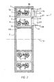
- Fig. 2 shows entrances 13, 14 which each belong to one of the wheels 3, 4 and are provided with a door 23, 24 or other type of closure. These entrances 13, 14 are arranged in a fixed position with respect to or in the housing 2, which in this case is made of concrete or concrete elements. Via each of the entrances 13, 14 it is possible to obtain access to the bicycle parking element 6, 7 of the wheel 3, 4 which is present at that location, these elements in this case being designed with an open front side.
- each bicycle parking element 6, 7 may be separately provided with its own closeable entrance door, in which case the doors 23, 24 could be dispensed with.
- each bicycle parking element 6, 7 is only accessible on one side, although it is also conceivable for the bicycle to be taken in and removed on opposite sides of each wheel.
- the entrances 13, 14 are positioned substantially vertically above the axis of rotation 51, so that the bicycles 50 can be placed in a vertical position in a bicycle parking element 6, 7.
- the entrances 13, 14 are of substantially the same dimensions as the surface area of the front side of the bicycle parking elements 6, 7 which interact with the entrances 13, 14. This makes it impossible to gain unauthorized access to an adjoining bicycle parking element 6, 7.
- the parking device 1 furthermore comprises a control unit 140, which is diagrammatically indicated in Figure 5 and controls a drive device 5 for driving the wheels 3, 4, for example via drive belts 8, 9 which are connected to drive rollers 15, 16. Other forms of drive are equally possible.
- the transmission of the drive device 5 may be of self-locking design, so that a wheel 3, 4 does not begin to rotate when a bicycle 50 is being placed in a bicycle parking element 6, 7 as a result of the weight of the user and/or the bicycle 50.
- the drive device 5 may be accommodated in the central space 12 surrounded by the inner wheel 3, so that the volume of the device is utilized optimally.
- the control unit 140 is used to control the drive 5 which, on the basis of a suitable command, rotates a wheel 3, 4 in order to position the desired bicycle parking element 6, 7 in front of the associated entrance 13, 14.
- the control unit 140 seeks to achieve a minimum disruption to balance by distributing the bicycles uniformly over the circumference of the wheels 3, 4 when the bicycles are being placed in the parking device 1. This results in a smaller and therefore less expensive drive.
- the control unit 140 also actuates the locking and unlocking of the doors 23, 24 of the entrances 13, 14.
- the control unit 140 also locks the wheels 3, 4 when the associated entrance 13, 14 is open, so that unauthorized access to the bicycles is prevented and the wheel 3, 4 is also prevented from rotating when the door is open.
- the control unit 140 can actuate an alarm which is activated in the event of unauthorized opening of the entrance 13, 14.
- the control unit 140 contains detection means 40 which detect the presence of a person in a bicycle parking element 6, 7, for example using infrared detection. This ensures that the entrance doors 23, 24 are only locked if it is certain that there is no one in the bicycle parking element 6, 7.
- the housing 2 is positioned partly below ground level and, in that section, is designed without openings, making the housing 2 liquid-tight in the section which is positioned below ground level. Consequently, it is possible, for example, to submerge the parking device 1 in water, for example in a canal or river. This has the advantage that hitherto unused area or empty space, for example in town centres, can be efficiently utilized without having an adverse effect on the infrastructure.
- the housing 2 can be positioned so far below ground level that the axis of rotation 51 is located below ground level.
- the entrances 13, 14 at the top side are located approximately at ground level, so that the access paths 60, 61 do not need any steep inclines or steps.
- the bicycle parking device 1 according to the invention is also aesthetically attractive.
- the parking device 1 does not have to project far above ground level, so that it can be virtually out of sight.
- ballast elements 17 are accommodated in the housing 2.
- the housing 2 may also be positioned on piles.
- the parking device 1 it is possible for the parking device 1 to be provided with float elements. In this context, consideration may be given, for example, to a pontoon on which the bicycle parking device 1 is positioned and which floats, for example, in the canal.
- Each wheel 3, 4 hangs from two associated bearing rollers 45, 46 which are attached to the housing 2. These bearing rollers 45, 46 are located above the axis of rotation 51, in the vicinity of the top side of the inner circumference of each wheel 3, 4, so that compressive loads are avoided as far as possible in the construction of the wheel 3, 4.
- the bearing rollers 45, 46 may also form part of the drive of the wheels 3, 4.
- the said bearing frame, together with the wheels 3, 4 positioned therein, may be removed entirely from the housing 2, for example using a crane.
- the axis of rotation 51 of the wheels 3, 4 forms a slight angle with the horizontal plane, with the result that the bicycles can easily be placed into the bicycle parking elements 6, 7 under the force of gravity. This effect is obtained here by making the base surface 10 of a parking element 6, 7 slope downwards at a slight angle.
- the parking device 1 is positioned substantially below ground level.
- a device 1 of this nature may, for example, also be used in an apartment building, in which case the device 1 is located entirely above ground level. Consequently, the entrances 13, 14 will be positioned on the underside. It follows from this that bicycles are arranged radially around the axis of rotation 51, but with the wheels directed outwards.
- Fig. 2 shows a vertical cross section through the parking device 1, with a number of bicycles 50 positioned in the bicycle parking elements 6, 7.
- Bicycle parking element 6, belonging to the inner wheel 3, is the bicycle parking element whose base surface 10 is positioned closest to the axis 51 (cf. also Fig. 1).
- bicycle parking elements 7 which have a base surface 10 which lies further away from the axis 51.
- the base surface 10 is arranged parallel to the axis 51. In an alternative embodiment, this surface may also be arranged so that it slopes down from the entrance 13, 14. In this case, when a bicycle is being placed in the bicycle parking element 6, the bicycle will roll as far as possible towards the rear wall of the bicycle parking element 6 under the force of gravity.
- a user wishing to park his bicycle will, for example, proceed along access path 60 to the entrance door 23 of the parking device 1, after which the control unit 140 actuates the drive device 5 in such a manner that the wheel 3 rotates about the axis of rotation 51 and a free bicycle parking element 6, 7 is positioned in front of the entrance 13, after which the user can open the entrance door 23 and park his bicycle.
- a locking means (not shown) will remain actuated, locking the wheel 3.
- This locking means may, for example, be in the form of a pin which projects into a recess in the wheel (not shown).
- the user parks his bicycle in the bicycle parking element 6, after which the entrance door 23 is closed.
- automatic bicycle-securing means which are to be described in more detail below, are activated, automatically securing the bicycle in place.
- a locking mechanism is actuated so that it locks the entrance door 23.
- the control unit 140 actuates the drive device 5 in such a manner that the corresponding bicycle parking element 6, 7 in which the bicycle 50 of the user in question is located is positioned in front of the entrance 13, 14.
- the bicycle-securing means then automatically release the bicycle and, after this, the user can open the entrance door 23, 24 and take his bicycle out of the bicycle shed 1.
- the bicycle parking element 7 is positioned at a greater distance from the axis 51 than the adjacent bicycle parking element 6.
- the base surface 10 has an upwardly sloping section 80 at its front in the vicinity of the entrance 14, so that the bicycle 50 automatically moves into the elevated position when it is being introduced. It is also possible for the base surface 10 to slope downwards after the upwardly sloping section 80, in accordance with the arrangement described above. Naturally, it is possible to provide an upwardly sloping surface instead of the upwardly sloping section 80 at the entrance 24.
- Fig. 3 diagrammatically depicts how the bicycles 50 are positioned at staggered heights with respect to one another in the bicycle parking elements 6, 7.
- the entrances 13, 14 may also have corresponding different shapes in accordance with the different shapes of the openings of the bicycle parking element 6, 7. As also shown in Fig. 2, this may also result in the entrance doors 23, 24 being of different shapes in accordance with the entrances 13, 14.
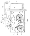
- Fig. 4 shows a bicycle parking element 6 with a base surface 10 which slopes downwards at a slight angle from the entrance 13.
- the base surface 10 may be provided with a U-shaped channel profile in which the wheels 101, 102 of the bicycle 50 can be guided.
- the front wheel of the bicycle 50 moves virtually onto the rear wall 50 in the bicycle parking element 6.
- the bicycle 50 is temporarily clamped upright in the bicycle parking element 6.
- the user can then close the entrance door 23, 24 of the bicycle parking element 6, after which automatic bicycle-securing means 110, 120 become active, which fix the bicycle so securely that it remains in place while the wheel is turning.
- the clamp 41 it is also possible for the clamp 41 not to be present.
- the user will then manually actuate a first bicycle-securing means 110 in order to prevent the bicycle from falling over, so that the bicycle stands in a defined position.
- automatically acting bicycle-securing means 120 then become active.
- the user may also secure the bicycle 50 completely manually using the bicycle-securing means 110, 120, after which the user closes the entrance door.
- the bicycle-securing means 110, 120 may also be of single-part design, in which case it is preferable for bicycle-securing means 120 to act on the saddle 103 of the bicycle.
- Fig. 4 diagrammatically depicts a control unit 140 which, via control signal 141, can control the drive device 5 (diagrammatically depicted by R1). Furthermore, control unit 140 regulates the locking and unlocking of the wheel by means of control signal 142, diagrammatically indicated by R2.
- control signal 142 diagrammatically indicated by R2.
- the control unit 140 In order for a correct bicycle 50 to be positioned in front of an entrance 13, the user has to input a code by means of a keypad 145, so that the control unit 140 can determine the correct user for the correct bicycle 50, and can then rotate the correct bicycle parking element 6, 7 to in front of the entrance 13, 14.
- Control unit 140 also carries out monitoring by means of detection means 40 and proximity sensor 146, which respectively enable the control unit 140 via the signals 143, 144.
- proximity sensor 146 detects that the door 23 is not closed, the wheel 3, 4 will be unable to move, and if detection means 40 detects a user in the bicycle parking element 6, the latter will use control unit 140 to prevent rotation of the wheel 3, 4 and locking of entrance 13.
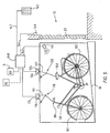
- Fig. 5 shows the bicycle-securing means 110, 120 which have been activated after the entrance door 23 has been closed.
- the bicycle-securing means 110, 120 press the bicycle towards the base surface 10, so that the wheels 101, 102 of the bicycle cannot come off the base surface 10 in any position of the wheel 3, 4.
- the bicycle-securing means 110, 120 may be designed in numerous ways and, in the embodiment shown in Figures 4 and 5, are designed in such a manner that they engage on the bicycle from above and press it towards the base.
- a bicycle-engaging means 111, 121 can be moved up and down, in this example via a linkage 112, 122, with pivots 113, 114 and 123, 124.
- the movement of the bicycle-engaging means 111, 121 is brought about by means of a drive device 115, 125.
- a drive device of this nature comprises a crank-connecting rod mechanism, but obviously other mechanical solutions or, for example, hydraulic and pneumatic drives are also possible.
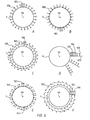
- Fig. 6 diagrammatically depicts alternative arrangements of bicycles for a parking device according to the invention.
- Fig. 6 diagrammatically depicts alternative arrangements of bicycles for a parking device according to the invention.
- only one wheel 4 is illustrated, on which bicycle parking elements containing bicycles are diagrammatically depicted.
- the bicycles 100 are arranged radially next to one another, in which arrangement there is a relatively large amount of space between the bicycles.
- the bicycles are introduced and removed at the top side of the wheel.
- 6b shows the bicycles 50 positioned radially around the wheel 4, but in this case the entrance 105 to the bicycle parking element 6, 7 is positioned at the bottom side of the wheel.
- Fig. 6c shows the staggered arrangement in which the bicycles 100 are arranged alternately at a relatively great and a relatively short distance from the axis of rotation 99. This arrangement may also be inverted in a similar manner to Fig. 6b (not shown). The entrances 105, 106 are situated at the top side.
- Fig. 6d shows a radially arranged base surface 200 on which the bicycles can be positioned.
- Fig. 6e shows an alternative arrangement of the bicycles 100 in which the bicycles which are arranged “upright” around the outer wheel 4 can be introduced and removed at the top side of the wheel, and the bicycles which are positioned “upside down” around the outer wheel 4 can be introduced and removed at the bottom side of the wheel 4 via entrance 106.
- Fig. 6f shows an arrangement in which the bicycles 100 do not form a right angle with the tangent of the wheel. In this case, the positioning of the entrances 105, 106 must be selected appropriately.
- Figs. 6a-6f show a number of embodiments of the invention which, however, do not limit the present invention.
- the entrance is selected in such a manner that the base surface of the bicycle parking element is substantially horizontal with respect to ground level when it has been rotated to in front of the entrance, and is diagrammatically depicted in the figures by means of a rectangle 105, 106.
- the longitudinal axis of the bicycle parking elements is oriented substantially parallel to the axis of rotation.
- the bicycle parking elements comprise bicycle - securing means and are rigidly connected to the wheels, with the result that the bicycle parking elements and their base surfaces maintain the same orientation with respect to the wheels irrespective of the position of the wheels.
- the bicycle parking elements are designed in such a manner that the bicycle frames are oriented substantially radially with respect to the axis of rotation.
- each bicycle parking element comprises at least two side walls.
- Parking device characterized in that the base surface of a bicycle parking element is directed towards the axis of rotation.
- Parking device according to one or more of the preceding paragraphs, characterized in that adjacent bicycle parking elements are staggered in the longitudinal direction with respect to one another.
- each bicycle parking element has an open front side.
- Parking device characterised in that the open front side of a bicycle parking element can be closed and locked.
- Parking device characterized in that there are detection means which are able to establish whether a person is present in a bicycle parking element.
- Parking device according to one or more of the preceding paragraphs, characterized in that the wheels can rotate independently of one another.
- Parking device according to one or more of the preceding paragraphs, characterized in that each wheel can rotate in both directions.
- Parking device characterized in that there are a plurality of wheels which are arranged concentrically with respect to one another.
- Parking device characterized in that there is a bearing frame which supports the wheels.
- Parking device characterized in that there are rollers which are positioned along the circumference of the wheels and support the wheels.
- Parking device characterized in that at least one roller is arranged on the inside of the wheel and above the plane parallel to ground level running through the axis of rotation is arranged on the wheel.
- the parking device comprises a housing in which the one or more wheels are positioned.
- Parking device characterized in that the wheels are positioned in a housing which, in the section positioned below ground level, is designed without openings, with the result that the housing is liquid-tight in the section positioned below ground level.
- Parking device according to one or more of the preceding paragraphs, characterized in that the device comprises foundation piles which support the housing.
- Parking device according to one or more of the preceding paragraphs, characterized in that the parking device comprises float elements.
- Parking device characterized in that the housing is provided at each wheel with at least one entrance, in order to provide access to the bicycle parking elements of the said wheel.
- Parking device characterized in that at each entrance there is a closure means, preferably with associated locking means for locking the entrance.
- Parking device characterized in that an entrance is of substantially the same dimensions as the open front side of a bicycle parking element.
- each entrance is positioned substantially vertically above the axis of rotation.
- Parking device characterized in that a plurality of entrances which interact with bicycle parking elements of the same wheel are positioned next to one another.
- Parking device according to one or more of the preceding paragraphs, characterized in that the axis of rotation is positioned substantially below ground level.
- Parking device according to one or more of the preceding paragraphs, characterized in that the axis of rotation is formed at a slight angle with respect to the horizontal plane.
- Parking device characterized in that locking means are provided which, in the open position of an entrance, lock the corresponding wheel.
- Parking device according to one or more of the preceding paragraphs, characterized in that there is a drive device which is able to drive the wheels.
- Parking device according to one or more of the preceding paragraphs, characterized in that the drive device is self-locking.
- Parking device according to one or more of the preceding paragraphs, characterized in that there is a control unit for controlling the drive device of each wheel.
- Parking device according to one or more of the preceding paragraphs, characterized in that the control unit is designed to balance each wheel.
- Parking device according to one or more of the preceding paragraphs, characterized in that the control unit is coupled to the locking means belonging to each entrance.
- control unit comprises an electronic system for the identification of the user.
- Parking device characterized in that there is an alarm which is activated in the event of unauthorized opening of an entrance.
- each wheel is composed of one or more connectable parts.
- Parking device according to one or more of the preceding paragraphs, characterized in that the drive device is accommodated in the central space formed by the inner wheel.
- Parking device according to one or more of the preceding paragraphs, characterized in that the central space of the inner wheel is suitable for accommodating a pipe.
- the bicycle-securing means comprise a bicycle front-wheel clamp.
- second bicycle-securing means which can be actuated by an associated drive and which, if an entrance is open, adopt a first unactuated position, and with a closed entrance adopt an actuated position, in which the bicycle is secured, the drive which actuates the second bicycle-securing means being activated after or through the closure of the entrance.
- the bicycle-securing means are designed with bicycle-engaging means which engage on the saddle of a bicycle which has been placed in the bicycle parking element.
- the bicycle-securing means are designed with bicycle-engaging means which engage on the handlebars of a bicycle which has been placed in the bicycle parking element.
Landscapes
- Engineering & Computer Science (AREA)
- Architecture (AREA)
- Civil Engineering (AREA)
- Structural Engineering (AREA)
- Traffic Control Systems (AREA)
- Steering Control In Accordance With Driving Conditions (AREA)
- Regulating Braking Force (AREA)
- Power Steering Mechanism (AREA)
- Steering Devices For Bicycles And Motorcycles (AREA)
- Lock And Its Accessories (AREA)
Claims (13)
- Vorrichtung (1) zum Parken von Fahrrädern, wobei die Parkvorrichtung ein oder mehr Räder (3-4) umfasst, die sich um eine gemeinsame, im Wesentlichen horizontale Drehachse (51) drehen können, wobei jedes Rad (3, 4) mehrere Fahrradparkelemente (6, 7) enthält,
wobei die Fahrradparkelemente (6, 7) mit dem entsprechenden Rad (3, 4) starr verbunden sind, so dass - unabhängig von der Position des Rades - die Fahrradparkelemente in Bezug auf das Rad die gleiche Orientierung beibehalten,
wobei jedes Fahrradparkelement mit einer Grundfläche (10) versehen ist,
wobei die Längsachse der Fahrradparkelemente (6, 7) zu der Drehachse (51) im Wesentlichen parallel orientiert ist,
dadurch gekennzeichnet, dass die Grundfläche (10) unabhängig von der Position des Rades (3, 4) in Bezug auf das Rad (3, 4) die gleiche Orientierung beibehält und dass jedes Fahrradparkelement (6, 7) mit einem Fahrradsicherungsmittel versehen ist. - Parkvorrichtung nach einem oder mehreren der vorhergehenden Ansprüche, dadurch gekennzeichnet, dass die Fahrradparkelemente (6, 7) so beschaffen sind, dass ein Fahrradrahmen eines geparkten Fahrrades in Bezug auf die Drehachse des Rades (3, 4) im Wesentlichen radial orientiert ist.
- Parkvorrichtung nach einem oder mehreren der vorhergehenden Ansprüche, dadurch gekennzeichnet, dass die Fahrradparkelemente (6, 7) eines Rades (3, 4) abwechselnd in verhältnismäßig großen und verhältnismäßig kleinen Abständen von der Drehachse des Rades positioniert sind.
- Parkvorrichtung nach einem oder mehreren der vorhergehenden Ansprüche, dadurch gekennzeichnet, dass jedes Fahrradparkelement (6, 7) wenigstens zwei Seitenwände (11) aufweist.
- Parkvorrichtung nach einem oder mehreren der vorhergehenden Ansprüche, dadurch gekennzeichnet, dass Erfassungsmittel (40) vorgesehen sind, die ermitteln können, ob in einem Fahrzeugparkelement eine Person vorhanden ist.
- Parkvorrichtung nach einem oder mehreren der vorhergehenden Ansprüche, dadurch gekennzeichnet, dass mehrere Räder (3, 4) vorgesehen sind, die sich unabhängig voneinander drehen können.
- Parkvorrichtung nach einem oder mehreren der vorhergehenden Ansprüche, dadurch gekennzeichnet, dass mehrere Räder (3, 4) vorgesehen sind, die konzentrisch zueinander angeordnet sind.
- Parkvorrichtung nach einem oder mehreren der vorhergehenden Ansprüche, dadurch gekennzeichnet, dass das eine oder die mehreren Räder (3, 4) in einem Gehäuse (2) positioniert sind, das vorzugsweise teilweise unter Bodenniveau zu positionieren ist, vorzugsweise so, dass die Drehachse des einen oder der mehreren Räder unter Bodenniveau positioniert ist.
- Parkvorrichtung nach Anspruch 8, dadurch gekennzeichnet, dass für jedes der Räder (3, 4) das Gehäuse mit einem oder mehreren entsprechenden Einlässen (13, 14) versehen ist, wobei die Fahrradparkelemente (6, 7) des Rades durch diese Einlässe zugänglich sind, und dass jedes Fahrradparkelement vorzugsweise mit einer offenen Vorderseite versehen ist, die durch Drehen des Rades in eine Linie mit einem Einlass gebracht werden kann, und dass jeder Einlass vorzugsweise mit einem entsprechenden Verschlussmittel versehen ist, vorzugsweise mit zugeordneten Verriegelungsmitteln zum Verriegeln des Einlasses.
- Parkvorrichtung nach einem oder mehreren der vorhergehenden Ansprüche, dadurch gekennzeichnet, dass eine Antriebsvorrichtung (5) zum Antreiben jedes der Räder (3, 4) vorhanden ist und dass eine Steuereinheit (140) zum Steuern der Antriebsvorrichtung jedes Rades vorgesehen ist, wobei die Steuereinheit vorzugsweise ein elektronisches System zum Identifizieren der das Fahrrad parkenden oder entnehmenden Person umfasst.
- Parkvorrichtung nach einem oder mehreren der vorhergehenden Ansprüche, dadurch gekennzeichnet, dass die Parkvorrichtung an jedem Fahrradparkelement mit einem Fahrradsicherungsmittel (110, 120) versehen ist, das durch einen entsprechenden Antrieb (115, 125) betätigt werden kann, wobei die Fahrradsicherungsmittel in einem nicht betätigten Zustand das Parken oder Entnehmen eines Fahrrades zulassen und in einem betätigten Zustand das Fahrrad in Bezug auf das Fahrradparkelement sichern, wobei der Antrieb, der die Fahrradsicherungsmittel betätigt, vorzugsweise automatisch aktiviert wird, entweder nachdem der Einlass zu dem Fahrradparkelement verschlossen wurde oder durch dieses Verschließen.
- Parkvorrichtung nach Anspruch 11, dadurch gekennzeichnet, dass die Fahrradsicherungsmittel (110, 120) mit Fahrradeingriffmitteln (111, 121) entworfen sind, die im Gebrauch mit dem Sattel eines Fahrrades, das in dem Fahrradparkelement angeordnet worden ist, und/oder mit der Lenkstange eines Fahrrades, das in dem Fahrradparkelement angeordnet worden ist, in Eingriff gelangen.
- Parkvorrichtung nach Anspruch 12, dadurch gekennzeichnet, dass die Fahrradsicherungsmittel (110, 120) so beschaffen sind, dass sie das Fahrrad zu der Grundfläche (10) drücken, so dass sich die Räder des Fahrrades in keiner Position des Rades (3, 4) von der Grundfläche (10) entfernen.
Applications Claiming Priority (2)
| Application Number | Priority Date | Filing Date | Title |
|---|---|---|---|
| NL1011380A NL1011380C2 (nl) | 1999-02-24 | 1999-02-24 | Stallingsinrichting voor fietsen. |
| NL1011380 | 1999-02-24 |
Publications (2)
| Publication Number | Publication Date |
|---|---|
| EP1031679A1 EP1031679A1 (de) | 2000-08-30 |
| EP1031679B1 true EP1031679B1 (de) | 2005-12-21 |
Family
ID=19768714
Family Applications (1)
| Application Number | Title | Priority Date | Filing Date |
|---|---|---|---|
| EP00200634A Expired - Lifetime EP1031679B1 (de) | 1999-02-24 | 2000-02-23 | Parkvorrichtung für Fahrräder |
Country Status (4)
| Country | Link |
|---|---|
| EP (1) | EP1031679B1 (de) |
| AT (1) | ATE313676T1 (de) |
| DE (1) | DE60024903T2 (de) |
| NL (1) | NL1011380C2 (de) |
Cited By (1)
| Publication number | Priority date | Publication date | Assignee | Title |
|---|---|---|---|---|
| WO2010091275A3 (en) * | 2009-02-08 | 2014-03-13 | Perry North | Automated bike parking system |
Families Citing this family (5)
| Publication number | Priority date | Publication date | Assignee | Title |
|---|---|---|---|---|
| NL2009242C2 (nl) * | 2012-07-27 | 2014-01-28 | W A Benecke Beheer B V | Opslag voor het ondergronds opslaan van fietsen. |
| DE102013001240A1 (de) * | 2013-01-25 | 2014-07-31 | Sew-Eurodrive Gmbh & Co Kg | Lageranordnung für Elektrofahrzeuge, insbesondere Elektrozweiräder, und System zur berührungslosen Energieübertragung |
| DK2924191T3 (en) * | 2014-03-28 | 2018-08-13 | Alluser Ind Srl | Anti-theft booth, especially for parking spaces for two-wheeled vehicles, such as bicycles and the like |
| EP3085856B1 (de) | 2015-04-21 | 2018-10-03 | Kairos Industrial AG | Aufbewahrungssystem für fahrzeuge |
| NL1041595B1 (nl) * | 2015-11-24 | 2017-06-30 | Hendrikus Johannes Van De Vecht Cornelis | Inrichting voor het parkeren van rijwielen. |
Family Cites Families (4)
| Publication number | Priority date | Publication date | Assignee | Title |
|---|---|---|---|---|
| GB2150611B (en) * | 1983-01-17 | 1986-05-21 | Michael Manning Lowing | Storage structures |
| DE4237042C1 (de) | 1992-11-03 | 1994-05-11 | Ulrich Kaczmarek | Vorrichtung zur Aufnahme und zeitlich begrenzten Speicherung einer Vielzahl von Fahrrädern |
| DE9410464U1 (de) * | 1994-07-01 | 1994-09-08 | EBF Ingenieurgesellschaft für Umwelt- und Bautechnik mbH, 01069 Dresden | Flexibles Aufbewahrungssystem |
| DE19545816C2 (de) | 1995-12-08 | 1999-10-28 | Rainer Korek | Fahrrad-Tresor in Trommelform |
-
1999
- 1999-02-24 NL NL1011380A patent/NL1011380C2/nl not_active IP Right Cessation
-
2000
- 2000-02-23 AT AT00200634T patent/ATE313676T1/de not_active IP Right Cessation
- 2000-02-23 DE DE60024903T patent/DE60024903T2/de not_active Expired - Lifetime
- 2000-02-23 EP EP00200634A patent/EP1031679B1/de not_active Expired - Lifetime
Cited By (1)
| Publication number | Priority date | Publication date | Assignee | Title |
|---|---|---|---|---|
| WO2010091275A3 (en) * | 2009-02-08 | 2014-03-13 | Perry North | Automated bike parking system |
Also Published As
| Publication number | Publication date |
|---|---|
| DE60024903D1 (de) | 2006-01-26 |
| NL1011380C2 (nl) | 2000-08-25 |
| ATE313676T1 (de) | 2006-01-15 |
| EP1031679A1 (de) | 2000-08-30 |
| DE60024903T2 (de) | 2006-07-27 |
Similar Documents
| Publication | Publication Date | Title |
|---|---|---|
| US5036951A (en) | Elevator-type storage system | |
| US20060228196A1 (en) | Car park | |
| US20070294952A1 (en) | Car park | |
| EP1031679B1 (de) | Parkvorrichtung für Fahrräder | |
| EP0603884A2 (de) | Radiales, mechanisiertes Parkgaragensystem | |
| CA2236481A1 (en) | Method for parking and retrieval of a vehicle and device thereto | |
| EP0847472B1 (de) | Parkhaus für fahrräder | |
| WO2009017508A1 (en) | Moving retail space system for buildings | |
| KR20110030246A (ko) | 자전거용 주차타워 | |
| CN1563646A (zh) | 智能型星形分布式地下立体车库 | |
| US7137755B2 (en) | Underground water retention apparatus | |
| JP3605739B2 (ja) | 防水扉の起立装置 | |
| KR101131017B1 (ko) | 자전거용 주차타워 | |
| CA2022524A1 (en) | Automobile vehicles stack parking system | |
| CN213625712U (zh) | 一种市政安全型窨井 | |
| GB2405634A (en) | Storage apparatus for vehicles | |
| JPH0351487A (ja) | 地下立体駐車場 | |
| KR100397821B1 (ko) | 박스형 주차설비 | |
| KR102703812B1 (ko) | 주차환경개선유도형 주행로를 포함한 어부바주차장치 | |
| KR102146908B1 (ko) | 지하 설치용 다층형 주차 리프트 | |
| CN221737646U (zh) | 一种合理管理电动自行车停放的充电站 | |
| JP2001122171A (ja) | 二輪車載置台の車輪ストッパー方法 | |
| JP2004232453A (ja) | 駐車装置 | |
| KR20250159527A (ko) | 트렌치 받침대 | |
| KR100257659B1 (ko) | 주차장치 |
Legal Events
| Date | Code | Title | Description |
|---|---|---|---|
| PUAI | Public reference made under article 153(3) epc to a published international application that has entered the european phase |
Free format text: ORIGINAL CODE: 0009012 |
|
| AK | Designated contracting states |
Kind code of ref document: A1 Designated state(s): AT BE CH CY DE DK ES FI FR GB GR IE IT LI LU MC NL PT SE |
|
| AX | Request for extension of the european patent |
Free format text: AL;LT;LV;MK;RO;SI |
|
| 17P | Request for examination filed |
Effective date: 20010110 |
|
| AKX | Designation fees paid |
Free format text: AT BE CH CY DE DK ES FI FR GB GR IE IT LI LU MC NL PT SE |
|
| 17Q | First examination report despatched |
Effective date: 20030801 |
|
| GRAP | Despatch of communication of intention to grant a patent |
Free format text: ORIGINAL CODE: EPIDOSNIGR1 |
|
| GRAS | Grant fee paid |
Free format text: ORIGINAL CODE: EPIDOSNIGR3 |
|
| GRAA | (expected) grant |
Free format text: ORIGINAL CODE: 0009210 |
|
| AK | Designated contracting states |
Kind code of ref document: B1 Designated state(s): AT BE CH CY DE DK ES FI FR GB GR IE IT LI LU MC NL PT SE |
|
| PG25 | Lapsed in a contracting state [announced via postgrant information from national office to epo] |
Ref country code: IT Free format text: LAPSE BECAUSE OF FAILURE TO SUBMIT A TRANSLATION OF THE DESCRIPTION OR TO PAY THE FEE WITHIN THE PRESCRIBED TIME-LIMIT;WARNING: LAPSES OF ITALIAN PATENTS WITH EFFECTIVE DATE BEFORE 2007 MAY HAVE OCCURRED AT ANY TIME BEFORE 2007. THE CORRECT EFFECTIVE DATE MAY BE DIFFERENT FROM THE ONE RECORDED. Effective date: 20051221 Ref country code: FI Free format text: LAPSE BECAUSE OF FAILURE TO SUBMIT A TRANSLATION OF THE DESCRIPTION OR TO PAY THE FEE WITHIN THE PRESCRIBED TIME-LIMIT Effective date: 20051221 Ref country code: LI Free format text: LAPSE BECAUSE OF FAILURE TO SUBMIT A TRANSLATION OF THE DESCRIPTION OR TO PAY THE FEE WITHIN THE PRESCRIBED TIME-LIMIT Effective date: 20051221 Ref country code: AT Free format text: LAPSE BECAUSE OF FAILURE TO SUBMIT A TRANSLATION OF THE DESCRIPTION OR TO PAY THE FEE WITHIN THE PRESCRIBED TIME-LIMIT Effective date: 20051221 Ref country code: CH Free format text: LAPSE BECAUSE OF FAILURE TO SUBMIT A TRANSLATION OF THE DESCRIPTION OR TO PAY THE FEE WITHIN THE PRESCRIBED TIME-LIMIT Effective date: 20051221 |
|
| REG | Reference to a national code |
Ref country code: GB Ref legal event code: FG4D |
|
| REG | Reference to a national code |
Ref country code: CH Ref legal event code: EP |
|
| REG | Reference to a national code |
Ref country code: IE Ref legal event code: FG4D |
|
| REF | Corresponds to: |
Ref document number: 60024903 Country of ref document: DE Date of ref document: 20060126 Kind code of ref document: P |
|
| PG25 | Lapsed in a contracting state [announced via postgrant information from national office to epo] |
Ref country code: IE Free format text: LAPSE BECAUSE OF NON-PAYMENT OF DUE FEES Effective date: 20060223 |
|
| PG25 | Lapsed in a contracting state [announced via postgrant information from national office to epo] |
Ref country code: LU Free format text: LAPSE BECAUSE OF NON-PAYMENT OF DUE FEES Effective date: 20060228 Ref country code: MC Free format text: LAPSE BECAUSE OF NON-PAYMENT OF DUE FEES Effective date: 20060228 |
|
| PG25 | Lapsed in a contracting state [announced via postgrant information from national office to epo] |
Ref country code: SE Free format text: LAPSE BECAUSE OF FAILURE TO SUBMIT A TRANSLATION OF THE DESCRIPTION OR TO PAY THE FEE WITHIN THE PRESCRIBED TIME-LIMIT Effective date: 20060321 Ref country code: GR Free format text: LAPSE BECAUSE OF FAILURE TO SUBMIT A TRANSLATION OF THE DESCRIPTION OR TO PAY THE FEE WITHIN THE PRESCRIBED TIME-LIMIT Effective date: 20060321 Ref country code: DK Free format text: LAPSE BECAUSE OF FAILURE TO SUBMIT A TRANSLATION OF THE DESCRIPTION OR TO PAY THE FEE WITHIN THE PRESCRIBED TIME-LIMIT Effective date: 20060321 |
|
| PG25 | Lapsed in a contracting state [announced via postgrant information from national office to epo] |
Ref country code: ES Free format text: LAPSE BECAUSE OF FAILURE TO SUBMIT A TRANSLATION OF THE DESCRIPTION OR TO PAY THE FEE WITHIN THE PRESCRIBED TIME-LIMIT Effective date: 20060401 |
|
| PG25 | Lapsed in a contracting state [announced via postgrant information from national office to epo] |
Ref country code: PT Free format text: LAPSE BECAUSE OF FAILURE TO SUBMIT A TRANSLATION OF THE DESCRIPTION OR TO PAY THE FEE WITHIN THE PRESCRIBED TIME-LIMIT Effective date: 20060522 |
|
| REG | Reference to a national code |
Ref country code: CH Ref legal event code: PL |
|
| ET | Fr: translation filed | ||
| PLBE | No opposition filed within time limit |
Free format text: ORIGINAL CODE: 0009261 |
|
| STAA | Information on the status of an ep patent application or granted ep patent |
Free format text: STATUS: NO OPPOSITION FILED WITHIN TIME LIMIT |
|
| REG | Reference to a national code |
Ref country code: IE Ref legal event code: MM4A |
|
| 26N | No opposition filed |
Effective date: 20060922 |
|
| BECA | Be: change of holder's address |
Owner name: BICYCLE-PARK B.V.HOEVENWEG 1, NL-5652 AW EINDHOVEN Effective date: 20051221 |
|
| BECH | Be: change of holder |
Owner name: BICYCLE-PARK B.V. Effective date: 20051221 |
|
| REG | Reference to a national code |
Ref country code: GB Ref legal event code: 732E |
|
| NLS | Nl: assignments of ep-patents |
Owner name: BICYCLE-PARK B.V. Effective date: 20080307 |
|
| REG | Reference to a national code |
Ref country code: FR Ref legal event code: TP |
|
| PG25 | Lapsed in a contracting state [announced via postgrant information from national office to epo] |
Ref country code: CY Free format text: LAPSE BECAUSE OF FAILURE TO SUBMIT A TRANSLATION OF THE DESCRIPTION OR TO PAY THE FEE WITHIN THE PRESCRIBED TIME-LIMIT Effective date: 20051221 |
|
| PGFP | Annual fee paid to national office [announced via postgrant information from national office to epo] |
Ref country code: FR Payment date: 20100316 Year of fee payment: 11 |
|
| PGFP | Annual fee paid to national office [announced via postgrant information from national office to epo] |
Ref country code: BE Payment date: 20100225 Year of fee payment: 11 Ref country code: DE Payment date: 20100222 Year of fee payment: 11 Ref country code: GB Payment date: 20100225 Year of fee payment: 11 |
|
| PGFP | Annual fee paid to national office [announced via postgrant information from national office to epo] |
Ref country code: NL Payment date: 20100225 Year of fee payment: 11 |
|
| BERE | Be: lapsed |
Owner name: BICYCLE-PARK B.V. Effective date: 20110228 |
|
| REG | Reference to a national code |
Ref country code: NL Ref legal event code: V1 Effective date: 20110901 |
|
| GBPC | Gb: european patent ceased through non-payment of renewal fee |
Effective date: 20110223 |
|
| REG | Reference to a national code |
Ref country code: FR Ref legal event code: ST Effective date: 20111102 |
|
| PG25 | Lapsed in a contracting state [announced via postgrant information from national office to epo] |
Ref country code: BE Free format text: LAPSE BECAUSE OF NON-PAYMENT OF DUE FEES Effective date: 20110228 |
|
| PG25 | Lapsed in a contracting state [announced via postgrant information from national office to epo] |
Ref country code: NL Free format text: LAPSE BECAUSE OF NON-PAYMENT OF DUE FEES Effective date: 20110901 |
|
| PG25 | Lapsed in a contracting state [announced via postgrant information from national office to epo] |
Ref country code: FR Free format text: LAPSE BECAUSE OF NON-PAYMENT OF DUE FEES Effective date: 20110228 |
|
| PG25 | Lapsed in a contracting state [announced via postgrant information from national office to epo] |
Ref country code: GB Free format text: LAPSE BECAUSE OF NON-PAYMENT OF DUE FEES Effective date: 20110223 |
|
| REG | Reference to a national code |
Ref country code: DE Ref legal event code: R119 Ref document number: 60024903 Country of ref document: DE Effective date: 20110901 |
|
| PG25 | Lapsed in a contracting state [announced via postgrant information from national office to epo] |
Ref country code: DE Free format text: LAPSE BECAUSE OF NON-PAYMENT OF DUE FEES Effective date: 20110901 |