EP0603884A2 - Radiales, mechanisiertes Parkgaragensystem - Google Patents
Radiales, mechanisiertes Parkgaragensystem Download PDFInfo
- Publication number
- EP0603884A2 EP0603884A2 EP93120795A EP93120795A EP0603884A2 EP 0603884 A2 EP0603884 A2 EP 0603884A2 EP 93120795 A EP93120795 A EP 93120795A EP 93120795 A EP93120795 A EP 93120795A EP 0603884 A2 EP0603884 A2 EP 0603884A2
- Authority
- EP
- European Patent Office
- Prior art keywords
- elevator
- cabin
- car
- rotatory
- metallic
- Prior art date
- Legal status (The legal status is an assumption and is not a legal conclusion. Google has not performed a legal analysis and makes no representation as to the accuracy of the status listed.)
- Granted
Links
- 230000009471 action Effects 0.000 claims description 16
- 230000007246 mechanism Effects 0.000 claims description 13
- 238000012546 transfer Methods 0.000 claims description 13
- 239000012530 fluid Substances 0.000 claims description 9
- 230000011664 signaling Effects 0.000 claims description 8
- 229910000831 Steel Inorganic materials 0.000 claims description 7
- 239000010959 steel Substances 0.000 claims description 7
- 230000002787 reinforcement Effects 0.000 claims description 6
- 238000004891 communication Methods 0.000 claims description 5
- 230000001174 ascending effect Effects 0.000 claims description 4
- 238000009434 installation Methods 0.000 claims description 4
- 238000012423 maintenance Methods 0.000 claims description 3
- 230000009467 reduction Effects 0.000 claims description 3
- 230000002459 sustained effect Effects 0.000 claims description 3
- 230000015556 catabolic process Effects 0.000 claims description 2
- 230000000694 effects Effects 0.000 claims description 2
- 230000002829 reductive effect Effects 0.000 abstract description 5
- 230000004888 barrier function Effects 0.000 description 12
- 239000003921 oil Substances 0.000 description 6
- 230000005540 biological transmission Effects 0.000 description 5
- 238000010276 construction Methods 0.000 description 5
- 239000011150 reinforced concrete Substances 0.000 description 5
- 230000002441 reversible effect Effects 0.000 description 5
- 230000008901 benefit Effects 0.000 description 4
- 239000006096 absorbing agent Substances 0.000 description 3
- 239000004567 concrete Substances 0.000 description 3
- 239000010720 hydraulic oil Substances 0.000 description 3
- 230000001681 protective effect Effects 0.000 description 3
- 239000002184 metal Substances 0.000 description 2
- 230000036961 partial effect Effects 0.000 description 2
- 230000035939 shock Effects 0.000 description 2
- 239000007787 solid Substances 0.000 description 2
- 229910000746 Structural steel Inorganic materials 0.000 description 1
- 230000001133 acceleration Effects 0.000 description 1
- 238000013459 approach Methods 0.000 description 1
- 230000000903 blocking effect Effects 0.000 description 1
- 239000003638 chemical reducing agent Substances 0.000 description 1
- 238000012790 confirmation Methods 0.000 description 1
- 230000001276 controlling effect Effects 0.000 description 1
- 238000013461 design Methods 0.000 description 1
- 238000001514 detection method Methods 0.000 description 1
- 238000006073 displacement reaction Methods 0.000 description 1
- 230000006870 function Effects 0.000 description 1
- 238000000034 method Methods 0.000 description 1
- 238000012986 modification Methods 0.000 description 1
- 230000004048 modification Effects 0.000 description 1
- 230000003287 optical effect Effects 0.000 description 1
- 239000004033 plastic Substances 0.000 description 1
- 238000003825 pressing Methods 0.000 description 1
- 230000008569 process Effects 0.000 description 1
- 238000011084 recovery Methods 0.000 description 1
- 230000001105 regulatory effect Effects 0.000 description 1
- 230000004044 response Effects 0.000 description 1
- 230000000452 restraining effect Effects 0.000 description 1
- 230000000630 rising effect Effects 0.000 description 1
- 239000002689 soil Substances 0.000 description 1
- 230000003068 static effect Effects 0.000 description 1
- 230000001360 synchronised effect Effects 0.000 description 1
- 230000007306 turnover Effects 0.000 description 1
- 210000001364 upper extremity Anatomy 0.000 description 1
- XLYOFNOQVPJJNP-UHFFFAOYSA-N water Substances O XLYOFNOQVPJJNP-UHFFFAOYSA-N 0.000 description 1
Images


Classifications
-
- E—FIXED CONSTRUCTIONS
- E04—BUILDING
- E04H—BUILDINGS OR LIKE STRUCTURES FOR PARTICULAR PURPOSES; SWIMMING OR SPLASH BATHS OR POOLS; MASTS; FENCING; TENTS OR CANOPIES, IN GENERAL
- E04H6/00—Buildings for parking cars, rolling-stock, aircraft, vessels or like vehicles, e.g. garages
- E04H6/08—Garages for many vehicles
- E04H6/12—Garages for many vehicles with mechanical means for shifting or lifting vehicles
- E04H6/18—Garages for many vehicles with mechanical means for shifting or lifting vehicles with means for transport in vertical direction only or independently in vertical and horizontal directions
- E04H6/181—Garages for many vehicles with mechanical means for shifting or lifting vehicles with means for transport in vertical direction only or independently in vertical and horizontal directions the cars rolling freely from the transfer means
-
- E—FIXED CONSTRUCTIONS
- E04—BUILDING
- E04H—BUILDINGS OR LIKE STRUCTURES FOR PARTICULAR PURPOSES; SWIMMING OR SPLASH BATHS OR POOLS; MASTS; FENCING; TENTS OR CANOPIES, IN GENERAL
- E04H6/00—Buildings for parking cars, rolling-stock, aircraft, vessels or like vehicles, e.g. garages
- E04H6/08—Garages for many vehicles
- E04H6/12—Garages for many vehicles with mechanical means for shifting or lifting vehicles
- E04H6/18—Garages for many vehicles with mechanical means for shifting or lifting vehicles with means for transport in vertical direction only or independently in vertical and horizontal directions
- E04H6/28—Garages for many vehicles with mechanical means for shifting or lifting vehicles with means for transport in vertical direction only or independently in vertical and horizontal directions characterised by use of turntables or rotary rings for horizontal transport
- E04H6/282—Garages for many vehicles with mechanical means for shifting or lifting vehicles with means for transport in vertical direction only or independently in vertical and horizontal directions characterised by use of turntables or rotary rings for horizontal transport turntables, rotary elevators or the like on which the cars are not permanently parked
Definitions
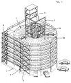
- This invention refers to a mechanized, radial type parking system, allowing twelve vehicles to be parked per floor without the need of areas for mane Fineng or circulation, and which applies to any urban area, especially where the land is scarce and expensive. The result is a high level of efficiency and density for vehicle parking as compared with the overall land and building area.
- a parking lot of this type is described in the applications for Mexican patents Nos. 927515 and 936173, belonging to the same titleholder of the present patent application.
- Previously-existing parking systems are very varied, and can be classified in non-mechanized and mechanized categories.
- the first provide ease of circulation to allow vehicles to move from the entrance to the parking space, whether located on a single ground-level floor, or on a higher floor where access is by means of a sloping ramp, or where the parking spaces form part of such ramp.
- These parking lots are characterized by low efficiency, high investment costs, the need for a large land and construction area, and low operating and maintenance costs.
- the second type of parking lots (mechanized) are characterized by a higher level of efficiency, ranging from those with a low level of sophistication which combine an elevator mechanism with circulation lanes, to fully mechanized systems where the vehicles are suspended in the lifting equipment itself or in vertically-placed niches. Use of the latter has been extremely restricted and for very specific applications, due to their high investment cost.
- the object of the present invention is, therefore, to provide parking for cars in a mechanized, radial-type system which is efficient, novel, functional and extremely economical for installation in urban areas.
- the other object of the present invention is to optimize the use of urban land areas by parking vehicles on two or more floors.
- Another object of the present invention is to eliminate car circulation, ascent and descent ramps and lanes, in order to better utilize the available construction area of the parking system.
- An additional object of the present invention is to have a car-lifting system which, once vehicles are lifted from one level to another, revolves on its own access to allow them to be placed at a suitable angle for ascent and descent.
- Another object of this invention is to provide parking where the dead weight of the building is relatively low when compared with the live weight of the cars ad their occupants, in order to reduce the investment costs.
- Yet another object of this invention is to provide a mechanized and semi-mechanized system to work faster in placing the cars, and which operates with a high degree of security for the occupants, the operating personnel, the vehicles and the parking system itself.
- a object of the present invention is to provide a modular parking system the capacity of which can be increased in accordance with the needs of each specific case, and which is easily made, put together and operated.
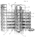
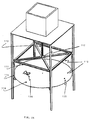
- a new parking system of the radial, mechanized type consisting basically of a foundation slab of reinforced concrete which will serve as a supporting platform for the structure of the building, as well as, serving as the lower floor of the parking system; a metallic or concrete structure with radial girders sustained by suitably-distributed columns for supporting both the dead weight of the building and the live weight of the cars and their occupants; a revolving elevator of a hydraulic or hydraulic with cables type in the center of each tower which, in addition to hoisting the vehicles, revolves around a central axis to acquire any of twelve preselected positions within 360°, a signalling and control system which allows the operator to identify unoccupied spaces and make the elevator cabin stop vertically on the desired floor and horizontally in the required position, while at the same time allowing safe operation of the elevator in order to prevent any movement or rotation while a vehicle is being lifted or lowered to the elevator cabin.
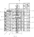
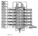
- the parking system of the present invention consist of a cylindrically-shaped building of two or more floors in the form of a circular crown, placed one obove the other in perfect alignment, in such a way that its structural elements coincide when seen from above.
- the floors are supported by columns in such a way that each floor has the capacity to house twelve radially-placed cars.
- a car elevator is placed in the center of the circular crown of each floor, which will raise or lower these to each floor or from each floor to ground level, and will position them by revolving on its central axis in the ascent or descent angle of the elevator required, according to the relative position of the parking space or point of exit.
- a feature of this elevator is that, in addition to its transfer movement, it also rotates the structural guide tower, the carlift and hydraulic lifting system.
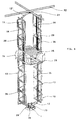
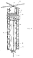
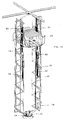
- the elevator consists of a vertical revolving structure which turns on its vertical longitudinal axis and which, in its lower part, serves as a support for the hydraulic lifting equipment and as a guide for the lifting cabin which runs vertically within the guide bars of structure itself.
- the metallic structure consists basically of a revolving table in the form of an inverted pyramid which supports two structural legs throughout the vertical length of the entire elevator and the hydraulic equipment, and whose upper extremity is another pyramid.
- Two central axis (an upper and a lower placed on the vertexes of the pyramids) formed by ball bearings, make up the revolving axis of the structure, the cabin and the hydraulic equipment by the action of an operator on the lower part of the table who, through a crown gear, a pinion and an electrical gearmotors, starts the rotatory movement which will permit the radial positioning of the elevator cabin in each of the twelve parking places corresponding to each of the floors.
- the elevator will be actived by an oleohydraulic system equipped with hydraulic pistons and pumps so that, when the pistons move outside the cylinders, the elevator cabin is raised, and vice versa.
- the elevator is also equipped with electrical and electronic controls to allow its ascent and descent operation, turn clockwise and counterclockwise, and controls to prevent its transfer and rotating movements if the vehices obstruct the light ray of the photocell installed at the entrance to the rotating platform of the elevator itself.
- the parking system will be equipped with a complete indication and control system, by means of which the equipment moves semiautomatically to allow the admission of cars, indication of vacant spaces, access, raising and rotation of the elevator, and the elevator call.
- the indication and control system consists basically of a logical control programmer, a control panel which governs the elevator, call buttons, obstruction sensors, positioning sensors and proximity sensors.
- the system as a whole will have a specially-designed operating language and logical programs for exercising the desired actions in accordance with the specific configuration of the equipment.
- the parking lot will be equipped with stairs and an elevator for transporting clients in order for users to be transported to or from each floor of the building.
- the first ones can consist or one or several floors where the vehicles circulate by a central horizontal, or sloping ascending lane, with parking spaces at the sides the cars require extensive space for circulation and a relatively large turning ratio for parking in battery form.
- the second, mechanized parking systems have evolved in some of the industriallized nations and usually include elevator systems or mechanical vehicle parking.
- the system presented here falls within the mechanized type parking, with different alternatives for transporting the cars and the automatization desired.
- This type of parking system can sufficient space for installing one or several towers of two floors or more, as needed.
- the parking building consists of a vertical structure, of either reinforced concrete or, preferably metallic, which is
- the building structure can be supported by foundations, depending on the specific conditions of the project, the height of the building, the overall weight, the soil conditions, etc.
- These foundations can take the form of an extended slab of reinforced concrete (1), isolated shoes or continuous foundations in the form of concentric circular rings.
- the floor on each level can be made of reinforced concrete slabs or, preferably, steel sheeting (7) of a caliber suitable for the live weight it must support, being in the form of a natural U and an inverted U fo form a continuous accordeon, thus achieving a substantial reduction in the weight of each level, with a reduced dead weight and a lower investment cost.
- the building will have stairs (8) and an elevator (9) for parking users, to be placed as shown in figures 1, 2, 3 and 4.
- the equipment will consist basically of two items, each covering various components of the system.
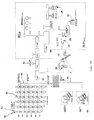
- the first item is the car elevator (10), in its various embodiments, and the signalling and control system (figure 11).
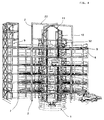
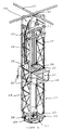
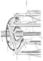
- the car elevator consists of a supporting, rotating and guiding structure (11), as shown in figures 5, 13, 15, 17, 20, 23, 25, 29, 32 and 36 related to each embodiment of the elevator, which is formed by two structured metallic columns (11) joined only at top and bottom which are vertically parallel and serve as a guide for the elevator cabin (25).
- the lower part of the structure (11) ends in a kind of inverted pyramid (12) (partially shown), where the lower corner acts as a rotating support for the entire tower, including the elevator cabin and hydraulic equipment, utilizing an axial type bearing (15) which is firmly attached to the foundations on one side, and to the lower inverted pyramid of the structure also ends in a kind of structural pyramid with a transversal element which joins the two legs of the structure (11) guiding the elevator, the pyramid having another bearing, in this case for axial type loads, in the center o vertex (21), the lower part of which is joined to the elevator tower (11), while its upper part is connected to four horizontal girders (22) forming a cross- shaped member.
- Girders (22) are, in turn, attached to four internal columns (2) of the parking building (figure 4), in order to keep the vertical rotating shaft of the elevator itself centered and properly aligned.
- the two structural metallic columns are composed of primary elements (11), which form a vertebral column in conjunction with secondary elements (13), which will increase their rigidity by providing better proportions, above all in parking system where it is necessary to install a greater number of floors.
- the primary vertically- placed structural elements (11) serve as support for installing the vertical parallel rails (17), which will guide the ascent or descent of the elevator cabin (25).
- the lower part of the elevator structure is also intended to house the elevator hydraulic system (19), consisting of the oleohydraulic tank, the hydraulic pressure pumps, the control valves and the cylinders (35), together with their hydraulic pistons (36) and, on the other hand, houses two electrical gearmotors (24), which are vertically placed and which at their ends, protruding from the rotor shaft, are connected by two pinion-type gears which turn around a circular crown (23) of straight gears which are firmly attached to the concrete foundation (1) of the elevator itself.
- the elevator hydraulic system (19) consisting of the oleohydraulic tank, the hydraulic pressure pumps, the control valves and the cylinders (35), together with their hydraulic pistons (36) and, on the other hand, houses two electrical gearmotors (24), which are vertically placed and which at their ends, protruding from the rotor shaft, are connected by two pinion-type gears which turn around a circular crown (23) of straight gears which are firmly attached to the concrete foundation (1) of the elevator itself.
- the drive of the two geramotors will result in the entire elevator (10) as a whole (metallic structure, cabin, hydraulic system, etc.) turning around the vertical shaft driven by the movement of the electric gearmotors (24) around the crown of gears (23).
- the motive elements consist of electric motors which receive a precise signals from the control system in order to adopt a position preselected by the master control of the logical control programmer, clockwise or counterclockwise, permitting a turn in the shortest direction between the original cabin position and final destination position.
- the oleohydraulic equipment of the elevator consists basically of the following essential elements: One or two metallic tanks (19) for storing and returning the system's hydraulic oil; one or two hydraulic pumps activated by electric motors (not shown in the drawings), which are placed inside the oleohydraulic tanks with a submerged type installation, and are moved by one or two electric motors (not shown) which, on functioning, inject the hydraulic oil through the control valves (not shown) towards the lower part of the hydraulic cylinder (35) placed on each side of the cabin (25), and running parallel to the metallic structure (11) and the guide rail (17).
- Two pulleys (20) are placed on the upper ends of the cylinder pistons (36), said pulleys supporting the elevator cables (34), and being fastened at one end to the structural base of the revolving tower (12) and, at the other end, are connected to the elevator cabin (25).
- the electric actuation of the hydraulic pump motors results in the oil from the storage tanks being injected at high pressure at the base of the hydraulic cylinders (35), which results in the pistons (36) being vertically displaced upwards and outwards, so that the metallic cables (34) fastened to the elevator cabin are displaced in one direction to that the cabin itself rises with a run equal to twice the stroke of the hydraulic pistons.
- the electric motors of the pumps turn anticlockwise, they will absorb oil from the hydraulic cylinders and transfer this to the storage tanks, retracting the pistons and displacing the metallic cables anticlockwise, so that the elevator cabin descends.
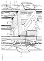
- the elevator cabin (25) consists of a box of metallic sheeting in parallelepiped form, suitably reinforced by structural elements (26) to allow it to be hoisted from the transversal ends, preventing their permanent deformation.
- Some guides (27) are placed on the upper and lower edges of the cabin, which can be the sliding shoe or revolving bearing type which engage the guide rails (17) on three sides, allowing the cabin to move vertically, perfectly guided, thus achieving the desired alignment of the cabin (25) throughout its vertical journey.
- Two metallic guides (28) are placed inside the cabin for car tires, so that these enter or leave the elevator in the direction and with the alignment required for their suitable functioning.
- the traps (29) consist, for example, of four structural steel plates or angles placed in reverse, which slide or turn by means of a gear and lever mechanism, which is moved by a mechanical actuator (30), with an electrical or reversible hydraulic motor, so that the angle wedges or plates in front of and behind the front wheels of cars to prevent their moving when the traps are applied, or are withdrawn by either sliding or turning a center at one end to withdrawn from the path of the vehicles and free the tires, allowing them to move over the guides (28) of the elevator cabin.
- Bipartite metallic doors (31) will be placed at both ends of the elevator cabin, which slide towards each side of the cabin.
- the doors are electrically operated by a mechanism which is actived once the elevator cabin has been vertically and angularly placed in front of each of parking spaces.
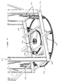
- Protective barriers (32) are placed on each floor of the parking building, around the car elevator shaft, for the purpose of preventing any person or car from coming too close to the open elevator shaft. These barriers are folding and are raised upwards by pushing a stem (33), which is moved automatically by an extension mechanism of the elevator itself, connected to the actuator (30) of the elevator traps.
- Two spring shock absorbers (18) are placed on the upper part of the turntable (12), the purpose of which is to progressively reduce the impact of a sudden descent of the elevator cabin.
- the signalling and control system of the parking system forms a basic part of same, since this permits the semiautomatic and safe operation of the entire system.
- a more advanced version of the same is the fully automatic control system, which is described as embodiment hereafter.
- the general configuration of the semiautomatic control system for the parking system takes various forms into consideration, based on the basic equipment, the sophistication of which can increase to the point where a fully automatic system is obtained.
- the basic equipment consists of the elements shown in figure 11.
- the instrumentation and control system consists basically of three interconnected subsystems to provide the necessary operating and safety conditions, which are:
- This system consists of one, two or three folding access barriers (37) and conventional ticket machines (38), which will have car presence detectors which permit these to enter when there are spaces available, or refuse entry when the signal of the Logical Control Programmer shows that there are no places available.
- this system includes the conventional collection system (39), which consists of a parking time reader which issues the cost when the time recorded is multiplied by the unit cost of the time unit. Both items of equipment, that for issuing tickets and that for reading and invoicing, can be replaced by access and exit equipment which utilized plastic cards with magnetic tapes, achieving the same effect.
- the system described here is connected to a logical control programmer and a conventional personal-type computer (40) which, in turn, forms part of the elevator operation and call sybsystem.
- ELEVATOR OPERATION AND CALL SUBSYSTEM This system consists basically of a Logical Control Programmer (41) with suitable entry and exit signals, for receiving occupation signals from each parking space, the permanent location of the elevator cabin, and to give the command signal to the elevator to attend a request.
- the Logical Control Programmer will have doors to connect the personal computer, which will have doors occupancy conditions and the calls pending answer on the monitor screen, together with the possibility of calculating invoicing and showing the operation acrual. It will also show autodiagnoses of the status of different system elements.
- the Logical Control Programmer has additionalä communication ports for connecting a portable programming computer, the card reader, a VHF frequency radio modem (42), the ticket issuer and the data channel or "bus" (43), obtained from the cable concentrators (44) on each floor of the parking building.
- each parking space There are two primary elements in each parking space which will transmit signals to the logical control programmer.
- the first are photoelectric cells (45), which will detect the presence or absence of a car in each space, showing their availability for occupancy, which will be located by means of the logical control programmer to a specific space as a possible destination of the elevator to unload cars.
- the second will be the call buttons (46) located in each parking space which, on being pushed, will request the presence of the elevator at the correct floor and in the correct radial position, to permit the exit of a specific car from the parking building.
- Both the photoelectric cells and the call buttons will be connected to the logical control programmer by means of cable concentrators (44), which will classify the signals to identify their origin and send them through a data bus to a signal converter (47) which will, in turn, be connected to the logical control programmer.
- the purpose of this invention is to command the actions of the elevator.
- Some of these are of the conventional type, such as the opening and closing of doors, the detection of door obstructions, the raising and descent of the elevator cabin, the closing of the hydraulic valves, the sequential registration of calls requesting the elevator and the floor destination to which the elevator should be sent.
- Others are completely innovative, such as th transmission by VHF bandradio (42) of requests from the different users located in parking space, the rotation of the elevator around its vertical shaft to place itself in a required radial position, application of the counterturn brake to avoid horizontal rotation, the permanent location of the cabin transmitted to the logical control programmer and application of the elevator cabin tire traps, among others.
- the control equipment consists of the conventional equipment used for elevators, which is not described since it is in common use, to which controls similar to that of vertical elevation will be added to achieve the startup, acceleration, deacceleration, stoppage and braking of the angular rotation motors of the elevator cabin by means of the speed reducers (24), which act on the gear crown (23).
- the speed reducers 24
- a cordless data transmission will be utilized, using a pair of "duplex" type transmitters/receivers on the VHF (Very High Frequency) waveband (42), connected to signal modulators for converting digital signals into radio signals and vice versa.
- the elevator cabin has a command panel with buttons (49) for indicating the desired destination to the control panel, with regard to the floor and the anular location of the specific space.
- buttons (49) for indicating the desired destination to the control panel, with regard to the floor and the anular location of the specific space.
- the safety control equipment is to be found within this subsystem, consisting of photoelectric cells on each of the elevator doors which avoids their closing if any obstruction exists, in which case they do not give the affirmative signal to the control panel for beginning the lifting and rotation movements; and, on the other hand, the starting controls of the tire trap actuators which, on being appplied, should similarly give permission to commence the lifting and rotation movements of the elevator cabin.
- the operation described is following the sequence of entering the car park, parking the car and, subsequently, leaving the parking building.
- All cars will arrive at the ground floor entrance, which can be one of the parking spaces (two or three), the sole purpose of which is to permit entrance.
- the automatic ticket issuer (38) will print the date and time and, if desirable, the exact location of a vacant space to which the parking of the vehicle has been allocated, and will send an automatic signal to the logical control programmer (41) notifying the presence of a car which wishes to enter, which will look for a vacant space as near as possible to the ground floor, in accordance with the period of time the vehicle is scheduled to be parked, which will be defined by the entrance space utilized.
- the entrance bar o barrier (37) When the driver takes the ticket, the entrance bar o barrier (37) will be lifted to allow the car to enter the ground floor parking space acting as a passage, to then enter the elevator cabin. If the cabin is not placed in front of this space, the ground floor protection barrier (32) will be in place, preventing the car from going farther. Once the elevator cabin (25) has been placed facing the access space, the barrier (32) will be vertically lifted, the doors (31) of the elevator cabin will be opened, the tire traps (29) will be released, and a green light will go on the advise the driver that the car should enter the elevator cabin.
- the elevator operator can see from the command panel which of the pilotlights is lighted, indicating a vacant space on a specific level.
- the operator gives an order to the logical control programmer (41) to commence the operation of the hydraulic pumps (19) of the car elevator (10), and the rotation movement of the platform will begin simultaneously, in order to place the elevator in the required direction.
- the first will be to draw back the piston of the safety barrier (32) on the ground floor, allowing it to fall, corresponding to the space where the car is located, and the safety device will be activated to prevent this rising solely by pushing same; the second, that the traps (29) be applied to the front wheels of the car, and the third is that of shutting the sliding doors (31) of the elevator cabin.
- the confirmation of these three actions by the logical control programmer (41) will give the command to begin opening the hydraulic valves connecting the hydraulic cylinders, and release of the counterturn brake of the horizontal rotation gearmotors (12), commencing the vertical transfer and rotation of the elevator cabin through the control panel and the respective motors (19 and 24).
- the hydraulic valves of the oleohydraulic plant and the counterturn brake of the rotation motors (24) will be automatically applied and the tire traps (29) will be deactived one by one, the elevator doors will be opened (31) and the protective barrier (32) corresponding to the parking space of destination will be lifted, allowing the driver of the vehicle to park this in reverse in the assigned space with the assistance and help of the elevator operator.
- the vehicle should be driven to some stops placed on the floor to limit the perimetral transit passage of pedestrians in the area, whether or not they are coming for their vehicles.
- the elevator can be requested by the driver of another vehicle on the same, or another, floor, or by the driver of any vehicle which is entering the parking building.
- the selection of priorities can be automatically programmed, or the elevator operator can decide manually, depending on the proximity of the space of the vehicle wishing to leave, or the demand for the entry or exit of vehicles at a certain time of day.
- drivers In order for a vehicle to be able to leave the parking building, drivers should reach same by using the passenger elevator (9) or the stairs (8), or the perimetral passages. Once within his vehicle, the driver should press the call button (46) for the elevator, located on the inside columns of the building at the height of the driver's window. At the same time, the driver should star his car and await the elevator.
- the elevator call button When the elevator call button is pushed, the signal is transferred through the cable concentrators (44) and the data bus (43) to the logical control programmer (41), which will process the call and send a codified signal to the VHF radio equipment which will, in wireless form, transmit this signal to the radio receiving equipment located close to the hydraulic system of the elevator.
- Signals are modulated and demodulated in order to be digitally fed to the car elevator control panel, in response to the request for positioning the elevator cabin (25), exactly opposite the parking space from which the call came.
- the signal can be stored in the waiting line control or automatically or manually executed directly by the operator, so that the elevator descends vertically with a circular movement in th desired direction.
- the counterturn brakes will again be applied and the hydraulic valves closed, the protective barrier will be lifted and the green light of the elevator parking lights will be put on the indicate that the vehicle can drive into the elevator cabin.
- No elevator operation can be carried out while the car is blocking the light ray from the photoelectric cells, signifying that the doors cannot be closed.
- the motor should be kept runnning, but with the brake on the avert any movement, in addition to the restraining action of the tire trap described above.
- the elevator on descending to the ground floor, should revolve as necessary in order for the platform to remain in such a way that the front of the vehicle is pointing towards the exit lane. Once the elevator has come to a standstill, the driver will be allowed to approach the payment booth, where he will deliver his ticket so that the amount owing can be calculated.
- the platform can revolve up to 360°, however, control will be programmed so that the maximum turn in any direction either clockwise or counterclockwise, is up to 180°, in order to minimize the time and length of the rotating movement.
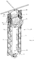
- Figures 12 and 13 represent an alternative embodiment of the radial parking system, in which the parking is similar to that previously described but with the difference that the elevator(10), instead of using cylinders with a single piston, use hydraulic cylinders (55) of the telescopic piston type, thus reducing the length of piston (56) to half if there are two telescopic piston sections, or to one-third in the case of four telescopic pistons.
- These telescopic cylinders are in common use, for which reason no further details are given here. The rest of the components, both for the building, the elevator, the controls, etc., remain as in the previous description.
- Figures 14 and 15 represent another embodiment of the radial parking system in which the latter is similar to those previously described, but with the variation that there is one hydraulic cylinder (57) instead of two, which is placed in the center of the elevator exactly below the platform, and is the same type as the telescopic cylinder with 2, 3 o 4 telescopic pistons.
- the piston would have a larger diameter, with a resulting larger pushing area if the same hydraulic pressure of the pump is maintained, and the length of the run will be equal to the length of the total height of the floors to which service is to be provided.
- the action of this piston is directed over the elevator cabin, and the ratio of run is, therefore, 1:1.
- pulleys (20), described in the previous versions, and the cables (34) which were connected to the structural girder (26) underneath the elevator cabin, are eliminated.
- the stroke speed of the piston is, in this case, equal to the speed of movement of the cabin.
- the use of cylinders with telescopic pistons (58) in 3 or 4 sections is preferred, in order to shorten the lenght of the cylinder which should be partially embedded in a central hole within the rotatory foundation of the elevator, within which the cylinder will be housed and will rotate inside at the time the elevator, including tower and cabin, rotates in order to acquire the necessary loading o unloading position.
- the remainder of all components, both of the building, the elevator, the instruments, etc., will remain unchanged in relation to the main embodiment of this invention.
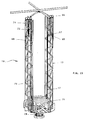
- FIG. 16 The embodiment proposed in Figures 16, 17 and 18 is characterized by a parking elevator (10) being moved by four cylinders (60) with a single piece tubular piston (not shown), or by telescopic pistons (61, 62), as in the case shown, which can be two, three or four-stage.
- This alternative embodiment can be used to advantage in installations where the number of floors to be served by the elevator are numerous, and the lenght of the cylinder and the pistons must be limited. At the same time, this embodiment reduces the diameter required for each piston by duplicating the number if pistons for the same given weight and the same hydraulic fluid pressure.
- the elevator system consists of a system similar to that described in the preferred embodiment, where a rotatory tower (11), is moved around a vertical center by two electric gearmotors (24), and which has a cabin (25) to lift the cars through a hydraulic system (19) consisting of an oil tank, hydraulic pumps, valves and four cylinders with hydraulic pistons, normal or telescopic type, which are placed vertically at the sides of the cabin, two in vertical ascending form and two in vertical descending form.
- a hydraulic system (19) consisting of an oil tank, hydraulic pumps, valves and four cylinders with hydraulic pistons, normal or telescopic type, which are placed vertically at the sides of the cabin, two in vertical ascending form and two in vertical descending form.
- Each of the pistons has a metallic pulley (63) at the protruding end, where the cables of flexible steel in the form of a leaning S are housed, and which at one end are fixed to the base plate (64) of the inverted pistons (62) and, at the other, to the elevator cabin (25), so that the movement transmission ratio is 4:1; that is, for each unit of distance travelled by the pistons (61, 62), the cabin travels four units of distance. In other words, the distance travelled by the cabin and the speed of ascent and descent is four times greater than that of the pistons.
- FIG. 19 Another embodiment is shown in Figures 19, 20 and 21 in which the parking system is similar to those previously shown but with the elevator featuring two sets of mechanisms consisting of pulleys, cables, counterweights and hydraulic pistons, to obtain vertical movement transmission ratios of 6:1.
- the system consists of two sets of five grooved pulleys placed on the upper part of the elevator tower, at each side of the cabin; three pulleys (66) are fixed at each side and the remaining two (67) are movable, and move vertically up or down; each of the pulleys having free rotatory movement.
- the movable pulleys (67) are linked by a metallic structure or member (68), which keeps them separated and includes at its ends two sliding guides for pulley rails (69), which will keep the movement straight throughout the journey of ascent or descent, which will only be one-sixth of the vertical journey of the elevator cabin (25).
- the rails are suitably supported and spaced from the secondary structure (11) of the elevator.
- Two counterweights (70) are hung from the center of the metallic structures (68) of the pulleys, the purpose of which is to reduce the power necessary for raising the elevator cabin plus the weight of the cars and their occupants.
- the total weight of the two counterweights will in fact be approximately equal to between 120% and 140% of the dead weight of the cabin, plus the elevator load.
- the mobile pulleys and the fixed pulleys are connected as shown in figure 19, by means of continuous flexible metal cables (71) in the form of a vertical zigzag with 6 steps, one end of the cables being fixed to the structure of the elevator tower (11) and the other to the elevator cabin.
- Below the counterweights are two cylinders with oleohydraulic pistons (72), which are supported by the elevator structure (11), and their pistons (73) work vertically underneath the counterweights.
- the form of operation consists of whether or not the cabin is loaded, oil is drained from the hydraulic cylinders, allowing the pistons to retract and lower the counterweights, so that the steel cables move one way only and the elevator cabin rises.
- This embodiment can result in substancial saving in the cost of the elevator mechanisms, since the needs of the oleohydraulic mechanisms is considerably reduced, and also gives us relatively large elevation distances with relatively small pistons.
- the embodiment proposed in figures 22, 23 and 24 corresponds to a parking system similar to those previously described but with the difference, as in the previous case, that the car elevator has a cable system (71), fixed pulleys (66) and hydraulic cylinders (72), with a transmission ratio of 6:1.
- the car elevator has a cable system (71), fixed pulleys (66) and hydraulic cylinders (72), with a transmission ratio of 6:1.
- the present invention can consists of two or more adjacent parking towers, utilizing the same passenger elevator services and stairs, with the possibility of transferring vehicles from one building to another should any operational problem arise in one of the car elevators.
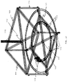
- the car elevator (110) consists of a supporting structure (111), in the form of a hollow paralelepiped, with a structural square containing diagonals and a center plate (112) on the upper face, hanging from the steel cables (113) which hoist the elevator cabin.
- Four structural legs (114) extend from the vertexes of the square which, in turn, support the lower face of the structure, which is similar to the upper face described above, but with the addition of a structural square (115), which serves to support the rollers (116) the purpose of which is described below.
- An axial load bearing hangs from the central part of the lower face, serving as a pivot for the circular movement of the elevator platform (118).
- the metallic sheeting platform (118) is circular and has an axis in the form of a solid shaft in its center and lower parts, and is placed on the lower face of the elevator structure and within the vertical legs forming the edges of the elevator structure.
- the platform (118) is reinforced in its lower part by two concentric circular channels (119, 119'), one channel (119) being placed within the periphere of the platform and the other channel (119') appproximately in the middle of the platform radius, the purpose of these channels being to stiffen the platform and to serve, at the same time, as a taxiway for the turning rollers (116).
- the turning rollers (116) will be placed in a minimum of twelve, and consist of rubber coated steel rolllers which contain a solid metallic shaft supported by two side bearings. Each roller group is suitably placed on the lower structure of the elevator (figure 27), and fixed by means os screws and nuts in a suitably angle position.
- the elevator platform can turn 360° by the action of two motors (120), which are vertically placed on the lower part of the platform, suitably fixed to the lower structure of the elevator (110).
- the two motors have pinion-type gears attached which, on turning, displace a sprocket (121) which is placed on the outside part of the internal reinforcement ring of the platform (118), andä therefore turn the platform.
- the motors (120) consist of an electric motor which receives specific signals from the control system in order to adopt a position previously selected by the master control of the logical control programmer. Having two motors, the turning system becomes redundant, thus increasing its reliability to 200%, and allowing a motor to turn the platform in one direction and the other in the other direction, one motor being idle while the other is working.
- the hoisting motor of the car elevator (122) is placed on the upper part of the parking center, and consists of the conventional parts of any passenger elevator, but with a larger capacity.
- the hoisting mechanism of the elevator consists of a gearmotor, with reversible action, traction pulleys for the cables, counterweights and electrical call, destination, emergency stops, alarm, etc., controls. In contrast to other conventional elevators, this possesses additional turning controls as described in the preceding paragraph.
- the signalling and control system of the parking system forms a substantive part of same, since it is this which allows semiautomatic and safe operation throughout the system.
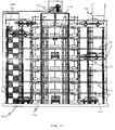
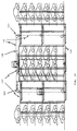
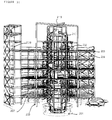
- FIG. 28 and 29 Another embodiment of the present invention is shown in figures 28 and 29, consisting of two adjacent towers (A, B) for radial parking, the height and distance between elevators of which is suitably modulated in such a way that the horizontal distance between the elevator centers is an exact multiple of the vertical distance between every two floors, and which has the speciality that the elevator has continuous action in a single direction, having a fixed number of platforms (137), as shown in figure 29.
- platforms for an arrangement of two towers with seven levels, there are eight platforms (137) joined by metal chains (138), placed at the ends of a diametral cord.
- Each of the platforms has its own rotating movement to place the platform at the desired angle with respect to the parking spaces for the cars.
- the plataforms joined by the traction chains (138) ascend by an elevator shaft and subsequently, when they reach the top floor of the parking building, move horizontally over a roller table (139), and then descend vertically within the elevator shaft of the adjoining tower, finally moving horizontally in the opposite direction over a second roller table (140) to close the cycle of movement.
- the chains are moved by racks (141) located in the four vertexes of the elevator's motive system, three of the racks being motorized, with the exception of the lower pulley located where the platforms descend.
- These racks (141) are impelled by electrical gearmotors of the capacity necessary to carry out the work of lifting the platforms or the movements over the upper and lower roller tables. The work of each motor is synchronized with the other two.
- Conveyance of the electromotive power necessary for the turning motors of the platforms is carried out by trolleys located on the lateral guides of the elevators and at one end of the roller tables.
- the control signals to establish the startup, positioning and stoppage of the platform rotative movement motors is of the shortwave radio type, or an optic sensor with the breadth and lenght of a regulated wave.
- the purpose of operating in this embodiment is to have a greater capacity for the entry and exit of cars from the parking system.
- the automatization degree is complete, each platform stopping automatically on each floor for a preestablished period of time, allowing drivers to place their cars in the center of elevator platforms through luminous traffic signals and audible instructions, following which the platforms descend vertically and turn with a rotatory movement until they find the preselected position and level, to descend radially to the desired parking space.
- the exit operation of the cars will be inverse to that of their entry, but with the same control and protection philosophy.
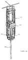
- the car elevator consists of a supporting, rotating and guiding structure formed by a lower metallic table (212), supported by six metallic rollers (213), which turn over a static circular rail (214) anchored to the parking building foundations (201).
- the table (212) has a turning shaft (215), permitting an angular displacement of up to 360°, consisting of a shaft which turns within one or several bearings which are rigidly supported in turn by a concrete jackbits which form part of the foundation.
- Four vertical metallic columns (211) are placed on the swivel table suitably stiffened with secondary structural elements (216) to reduce their slenderness ratio in the case of relatively high elevators.
- the four columns (211) serve also as support for fixing the guide rails (217) of the elevator, and the guide rails of the counterweight (235).
- An engine room is located in the upper part of the four columns (218), containing a traction engine (219) for elevator, together with the pulleys (229) necessary for same.
- An upper center of turning (221) is installed at the central part of the engine room, which also has a shaft and one or more bearings, fixed to structural girders (222) forming a cross-shaped structure which is linked with the internal columns (202) of the building, providing the uppermost center of turning of the elevator.
- two electrical gearmotors (224) are provided, suitably attached to the structure, with connected pinion-type gears (260) which are, in turn, duly geared in a circular ring (223), which is rigidly supported over the reinforced concrete foundations (201) of the parking building.
- These gearmotors on being placed in operation, will result in the rotation of the elevator (210) as a whole with the supporting structure (211), (212), (216), (218), (219) and (225).
- the use of two gearmotors has been chosen for the purpose of having a balanced turn at the opposite ends of the ring.
- the motive elements consist of an electric motor which receives precise signals from the control system, to adopt a position which has been preselected by the master control of the logical control programmer, clockwise or counterclockwise, allowing the turn to take place in the shortest direction between the original cabin position (225) and the final destination position.
- the equipment for hoisting the cabin vertically is of traditional elevator type, consisting of a gearmotor (219) with a reversible traction pulley, diverting pulleys (220), traction cables (234), cable pulleys (if the traction ratio is 2:1), a counterweight (235) and the necessary fittings to fasten same.
- Shock absorbers (236) are placed on the upper part of turntable (212), these being spring and oil absorbers, for the cabin (225) and counterweight (235), for the purpose of progressively reducing the impact of a sudden descent of the elevator cabin.
- the counterweight will move vertically up or down in accordance with the relative cabin position, for the purpose of reducing consumption of the power required to lift the cabin and the corresponding load of the car plus its occupants.
- the revolving structure of the elevator (211), in addition to the turntable (212), the rollers (213), the circular rail (214), the lower turn shaft (215), the guiding rails (217) and the upper center of turning (221) will remain unchanged.
- the traction machine (119) and the pulleys (120) are not needed.
- a hydraulic piston (251) fixed to the lower part of the parking lot is included, for which purpose it has a tubular cylindrical casing (250) which will be embedded in the ground and will have the same length as the hydraulic elevator piston (251).
- the casing (250) will contain the earth and water of the phreatic levels and act as a receptacle for the hydraulic piston (251).
- the piston is assembled on the turntable (212) and housed within the casing (250), without having contact with the casing because the piston will have a rotatory movement.
- An important part of the hydraulic piston is its stem, which moves up to down supporting the weight of the cabin and the weight of the car on applying the hydraulic pressure obtained from the hydraulic pumps (253) which, together with the hydraulic fluid tank (254), are also mounted on the elevator turntable (212).
- the gearmotors (224) and circular ring (223) continue to act in a way similar to that described in the cable traction elevator.
- the control panel will also be similar, but instead of commanding the electrical hoisting motor, will now start the hydraulic pumps in order to increase the pressure or the volume of the hydraulic fluid in the piston, and make the elevator ascend, or reduced these and send the hydraulic fluid coming from the piston to the storage tank, thus forcing the elevator cabin to descend.
Landscapes
- Engineering & Computer Science (AREA)
- Architecture (AREA)
- Mechanical Engineering (AREA)
- Civil Engineering (AREA)
- Structural Engineering (AREA)
- Types And Forms Of Lifts (AREA)
- Traffic Control Systems (AREA)
- Body Structure For Vehicles (AREA)
Applications Claiming Priority (6)
| Application Number | Priority Date | Filing Date | Title |
|---|---|---|---|
| MX9207515A MX9207515A (es) | 1992-12-23 | 1992-12-23 | Mejoras para un estacionamiento de automoviles a base de un estacionamiento mecanizado tipo radial |
| MX9207515 | 1992-12-23 | ||
| MX9306173 | 1993-10-04 | ||
| MX9306173 | 1993-10-04 | ||
| MX9307724 | 1993-12-07 | ||
| MX9307724 | 1993-12-07 |
Publications (3)
| Publication Number | Publication Date |
|---|---|
| EP0603884A2 true EP0603884A2 (de) | 1994-06-29 |
| EP0603884A3 EP0603884A3 (en) | 1994-08-24 |
| EP0603884B1 EP0603884B1 (de) | 1998-06-10 |
Family
ID=27350872
Family Applications (1)
| Application Number | Title | Priority Date | Filing Date |
|---|---|---|---|
| EP19930120795 Expired - Lifetime EP0603884B1 (de) | 1992-12-23 | 1993-12-23 | Radiales, mechanisiertes Parkgaragensystem |
Country Status (6)
| Country | Link |
|---|---|
| EP (1) | EP0603884B1 (de) |
| JP (1) | JPH06280418A (de) |
| BR (1) | BR9305221A (de) |
| CA (1) | CA2112163A1 (de) |
| DE (1) | DE69319079T2 (de) |
| ES (1) | ES2120472T3 (de) |
Cited By (16)
| Publication number | Priority date | Publication date | Assignee | Title |
|---|---|---|---|---|
| WO2000017470A1 (fr) * | 1998-09-23 | 2000-03-30 | Heidi Industriele Venootschap N.V. | Park lift |
| RU2260099C1 (ru) * | 2004-05-14 | 2005-09-10 | Основин Евгений Владимирович | Многоярусная стоянка (варианты) |
| RU2260100C1 (ru) * | 2004-05-14 | 2005-09-10 | Основин Евгений Владимирович | Многоярусная стоянка (варианты) |
| EP3196385A1 (de) * | 2016-01-21 | 2017-07-26 | DPG Deutsche Parken GmbH | Parkhaus für fahrzeuge, insbesondere hochgarage, und verfahren zur herstellung eines parkhauses |
| CN107140494A (zh) * | 2017-05-25 | 2017-09-08 | 浙江南奥电梯有限公司 | 一种高效汽车电梯及其操作方法 |
| CN107299785A (zh) * | 2017-08-18 | 2017-10-27 | 厦门市市政工程设计院有限公司 | 一种预制拼装式停车库及其施工安装方法 |
| CN111021802A (zh) * | 2019-12-06 | 2020-04-17 | 中国海洋大学 | 一种单驱动控制多层转盘独立转动的双环形立体车库 |
| CN111411804A (zh) * | 2019-01-07 | 2020-07-14 | 合肥后浪电子商务有限公司 | 小型空中圆形动态停车场 |
| WO2020243109A1 (en) * | 2019-05-24 | 2020-12-03 | Elreich Ahmad Abu | Transportation systems for hybrid vehicles |
| CN112634474A (zh) * | 2021-01-25 | 2021-04-09 | 深圳市驰远汽车科技有限公司 | 一种用于车辆的停车收费装置 |
| CN112854854A (zh) * | 2021-03-19 | 2021-05-28 | 王骏 | 停车机构以及停车系统 |
| CN112922412A (zh) * | 2021-01-28 | 2021-06-08 | 湖南汽车工程职业学院 | 一种基于大数据的智能停放和提取车辆的立体停车系统 |
| CN114922485A (zh) * | 2022-04-15 | 2022-08-19 | 湖北泊都智能科技有限公司 | 一种高层车库车辆举升装置 |
| WO2023101548A1 (en) * | 2021-12-01 | 2023-06-08 | Bahri Boudali | Method of constructing a structure with construction aids that are designed for permanent residence in the structure |
| CN119122351A (zh) * | 2024-11-12 | 2024-12-13 | 中铁十五局集团有限公司 | 一种具有履带式循环电梯系统的垂直地下车库 |
| CN119801036A (zh) * | 2025-03-13 | 2025-04-11 | 广东省电力线路器材厂有限公司 | 一种车库体地梁结构 |
Families Citing this family (11)
| Publication number | Priority date | Publication date | Assignee | Title |
|---|---|---|---|---|
| BRPI0418570A (pt) * | 2004-02-24 | 2007-06-19 | Y T Entpr Ltd | usina de potência de onda |
| CN100482911C (zh) * | 2006-06-23 | 2009-04-29 | 河北宏地停车设备有限公司 | 筒式组合密集型立体停车库 |
| BR102013028165B1 (pt) * | 2013-10-31 | 2021-11-03 | Carmine Alexandre Cifelli | Estacionamento de veículos em múltiplos níveis e método de gestão de manobras |
| CN104234479B (zh) * | 2014-09-05 | 2016-08-24 | 上海市政工程设计研究总院(集团)有限公司 | 一种用于地下立体停车库的组合式井筒状结构 |
| CN106958375B (zh) * | 2017-05-12 | 2022-09-23 | 安徽博微联控科技有限公司 | 立体车库中转台的安装结构 |
| CN109113401B (zh) * | 2018-08-27 | 2020-06-16 | 丽水学院 | 一种多功能自动化停车装置及其停车方法 |
| CN111219089B (zh) * | 2020-03-03 | 2025-05-23 | 林富玉 | 一种立体车库用车辆载运出入库系统 |
| CN111962944B (zh) * | 2020-07-31 | 2022-04-15 | 山东劳动职业技术学院(山东劳动技师学院) | 一种智能立体车库系统 |
| CN113944356A (zh) * | 2021-10-28 | 2022-01-18 | 洛阳理工学院 | 一种环形半地表智能停车库 |
| CN114396187A (zh) * | 2022-02-28 | 2022-04-26 | 江西奥德川自动化科技有限公司 | 一种可旋转式智能升降圆形车库 |
| CN114776108A (zh) * | 2022-04-27 | 2022-07-22 | 中国铁建重工集团股份有限公司 | 一种公交车立体车库系统 |
Family Cites Families (8)
| Publication number | Priority date | Publication date | Assignee | Title |
|---|---|---|---|---|
| US1966165A (en) * | 1932-05-19 | 1934-07-10 | James E Clyde | Automobile parking garage |
| GB1012579A (en) * | 1963-01-17 | 1965-12-08 | Anciens Etablissements Coulett | Construction for use as a garage for vehicles |
| CH408386A (de) * | 1963-05-28 | 1966-02-28 | Schuchter Willy | Hebevorrichtung, insbesondere für Fahrzeuge in Parkgaragen |
| US3497087A (en) * | 1968-01-19 | 1970-02-24 | Lawrence Vita | Automatic vehicle parking system |
| DE1759653A1 (de) * | 1968-05-24 | 1971-06-16 | Hasse Friedrich W Dipl Ing | Anlage zum Abstellen von Kraftfahrzeugen |
| DE1759691A1 (de) * | 1968-05-28 | 1971-11-18 | Josef Strakata | Automatische Hochgarage oder Parkturm,insbesondere in demontierbarer Bauweise fuer provisorische Grundstuecke der Innenstadt |
| CH500361A (fr) * | 1968-09-25 | 1970-12-15 | Habegger Virgile | Installation pour le parcage de véhicules automobiles |
| FR2075378A5 (de) * | 1971-01-08 | 1971-10-08 | Arnaud Jacques |
-
1993
- 1993-12-22 CA CA 2112163 patent/CA2112163A1/en not_active Abandoned
- 1993-12-23 ES ES93120795T patent/ES2120472T3/es not_active Expired - Lifetime
- 1993-12-23 DE DE1993619079 patent/DE69319079T2/de not_active Expired - Fee Related
- 1993-12-23 BR BR9305221A patent/BR9305221A/pt not_active Application Discontinuation
- 1993-12-23 EP EP19930120795 patent/EP0603884B1/de not_active Expired - Lifetime
- 1993-12-24 JP JP32861893A patent/JPH06280418A/ja active Pending
Cited By (19)
| Publication number | Priority date | Publication date | Assignee | Title |
|---|---|---|---|---|
| WO2000017470A1 (fr) * | 1998-09-23 | 2000-03-30 | Heidi Industriele Venootschap N.V. | Park lift |
| RU2260099C1 (ru) * | 2004-05-14 | 2005-09-10 | Основин Евгений Владимирович | Многоярусная стоянка (варианты) |
| RU2260100C1 (ru) * | 2004-05-14 | 2005-09-10 | Основин Евгений Владимирович | Многоярусная стоянка (варианты) |
| US10738496B2 (en) | 2016-01-21 | 2020-08-11 | Dpg Deutsche Parken Gmbh | Parking garage for motor vehicles, in particular multistory parking garage, and method for manufacturing a parking garage |
| EP3196385A1 (de) * | 2016-01-21 | 2017-07-26 | DPG Deutsche Parken GmbH | Parkhaus für fahrzeuge, insbesondere hochgarage, und verfahren zur herstellung eines parkhauses |
| CN107140494A (zh) * | 2017-05-25 | 2017-09-08 | 浙江南奥电梯有限公司 | 一种高效汽车电梯及其操作方法 |
| CN107299785A (zh) * | 2017-08-18 | 2017-10-27 | 厦门市市政工程设计院有限公司 | 一种预制拼装式停车库及其施工安装方法 |
| CN111411804A (zh) * | 2019-01-07 | 2020-07-14 | 合肥后浪电子商务有限公司 | 小型空中圆形动态停车场 |
| WO2020243109A1 (en) * | 2019-05-24 | 2020-12-03 | Elreich Ahmad Abu | Transportation systems for hybrid vehicles |
| US11434611B2 (en) | 2019-05-24 | 2022-09-06 | Ahmad Abu ELREICH | Transportation systems for hybrid vehicles |
| CN111021802A (zh) * | 2019-12-06 | 2020-04-17 | 中国海洋大学 | 一种单驱动控制多层转盘独立转动的双环形立体车库 |
| CN112634474A (zh) * | 2021-01-25 | 2021-04-09 | 深圳市驰远汽车科技有限公司 | 一种用于车辆的停车收费装置 |
| CN112922412A (zh) * | 2021-01-28 | 2021-06-08 | 湖南汽车工程职业学院 | 一种基于大数据的智能停放和提取车辆的立体停车系统 |
| CN112854854A (zh) * | 2021-03-19 | 2021-05-28 | 王骏 | 停车机构以及停车系统 |
| WO2023101548A1 (en) * | 2021-12-01 | 2023-06-08 | Bahri Boudali | Method of constructing a structure with construction aids that are designed for permanent residence in the structure |
| CN114922485A (zh) * | 2022-04-15 | 2022-08-19 | 湖北泊都智能科技有限公司 | 一种高层车库车辆举升装置 |
| CN114922485B (zh) * | 2022-04-15 | 2023-12-05 | 湖北泊都智能科技有限公司 | 一种高层车库车辆举升装置 |
| CN119122351A (zh) * | 2024-11-12 | 2024-12-13 | 中铁十五局集团有限公司 | 一种具有履带式循环电梯系统的垂直地下车库 |
| CN119801036A (zh) * | 2025-03-13 | 2025-04-11 | 广东省电力线路器材厂有限公司 | 一种车库体地梁结构 |
Also Published As
| Publication number | Publication date |
|---|---|
| ES2120472T3 (es) | 1998-11-01 |
| EP0603884B1 (de) | 1998-06-10 |
| CA2112163A1 (en) | 1994-06-24 |
| EP0603884A3 (en) | 1994-08-24 |
| DE69319079D1 (de) | 1998-07-16 |
| DE69319079T2 (de) | 1998-11-19 |
| JPH06280418A (ja) | 1994-10-04 |
| BR9305221A (pt) | 1994-07-26 |
Similar Documents
| Publication | Publication Date | Title |
|---|---|---|
| EP0603884A2 (de) | Radiales, mechanisiertes Parkgaragensystem | |
| US5829941A (en) | Radial mechanized garage parking system | |
| US20060228196A1 (en) | Car park | |
| US20070294952A1 (en) | Car park | |
| WO2002008545A2 (en) | Vehicle parking building and system | |
| CN104141399B (zh) | 一种半自动立体式地下车库 | |
| CN106869552B (zh) | 地下旋转式立体车库 | |
| CN1563646A (zh) | 智能型星形分布式地下立体车库 | |
| CN210768038U (zh) | 一种位于建筑物顶部的机械车库 | |
| JP7488347B2 (ja) | 立体駐車システム | |
| EP1618268B1 (de) | Vorrichtung zum lagern von objekten auf merhlagigen drehenden ringen | |
| CN213953159U (zh) | 一种垂直升降式立体停车设备 | |
| CN117306923A (zh) | 一种地下圆形智能停车库及存取车控制方法 | |
| CN117306924A (zh) | 一种低碳高效率复合地下智能停车库及存取车控制方法 | |
| CN212957877U (zh) | 停车模块及采用该停车模块组合构成的停车场 | |
| CN212453845U (zh) | 地上宽轿厢旋转升降机 | |
| RU2398946C2 (ru) | Многоуровневая карусельно-винтовая автостоянка | |
| CN210086929U (zh) | 一种改进的停车装置 | |
| CN111764719B (zh) | 停车模块及采用该停车模块组合构成的停车场 | |
| RU78246U1 (ru) | Многоместный подземный паркинг | |
| CN206769493U (zh) | 地下旋转式立体车库 | |
| RU2241812C2 (ru) | Многоярусный гараж для парковки и стоянки легковых автомобилей | |
| RU104601U1 (ru) | Многоярусная автомобильная автостоянка | |
| EP0573858B1 (de) | Mehrstöckige automatische Wagenparkanlage | |
| RU142290U1 (ru) | Многоярусный модульный автогараж |
Legal Events
| Date | Code | Title | Description |
|---|---|---|---|
| PUAI | Public reference made under article 153(3) epc to a published international application that has entered the european phase |
Free format text: ORIGINAL CODE: 0009012 |
|
| AK | Designated contracting states |
Kind code of ref document: A2 Designated state(s): CH DE ES FR GB IT LI NL |
|
| PUAL | Search report despatched |
Free format text: ORIGINAL CODE: 0009013 |
|
| AK | Designated contracting states |
Kind code of ref document: A3 Designated state(s): CH DE ES FR GB IT LI NL |
|
| 17P | Request for examination filed |
Effective date: 19950119 |
|
| 17Q | First examination report despatched |
Effective date: 19960514 |
|
| GRAG | Despatch of communication of intention to grant |
Free format text: ORIGINAL CODE: EPIDOS AGRA |
|
| GRAG | Despatch of communication of intention to grant |
Free format text: ORIGINAL CODE: EPIDOS AGRA |
|
| GRAH | Despatch of communication of intention to grant a patent |
Free format text: ORIGINAL CODE: EPIDOS IGRA |
|
| RAP3 | Party data changed (applicant data changed or rights of an application transferred) |
Owner name: ZAMORANO-MORFIN, LUIS RODOLFO |
|
| GRAH | Despatch of communication of intention to grant a patent |
Free format text: ORIGINAL CODE: EPIDOS IGRA |
|
| GRAA | (expected) grant |
Free format text: ORIGINAL CODE: 0009210 |
|
| AK | Designated contracting states |
Kind code of ref document: B1 Designated state(s): CH DE ES FR GB IT LI NL |
|
| REG | Reference to a national code |
Ref country code: CH Ref legal event code: EP |
|
| REF | Corresponds to: |
Ref document number: 69319079 Country of ref document: DE Date of ref document: 19980716 |
|
| REG | Reference to a national code |
Ref country code: CH Ref legal event code: NV Representative=s name: BUECHEL & PARTNER AG PATENTBUERO |
|
| ITF | It: translation for a ep patent filed | ||
| ET | Fr: translation filed | ||
| REG | Reference to a national code |
Ref country code: ES Ref legal event code: FG2A Ref document number: 2120472 Country of ref document: ES Kind code of ref document: T3 |
|
| PLBE | No opposition filed within time limit |
Free format text: ORIGINAL CODE: 0009261 |
|
| STAA | Information on the status of an ep patent application or granted ep patent |
Free format text: STATUS: NO OPPOSITION FILED WITHIN TIME LIMIT |
|
| 26N | No opposition filed | ||
| REG | Reference to a national code |
Ref country code: GB Ref legal event code: IF02 |
|
| REG | Reference to a national code |
Ref country code: FR Ref legal event code: ST |
|
| REG | Reference to a national code |
Ref country code: FR Ref legal event code: RN |
|
| REG | Reference to a national code |
Ref country code: FR Ref legal event code: FC |
|
| PGFP | Annual fee paid to national office [announced via postgrant information from national office to epo] |
Ref country code: ES Payment date: 20080626 Year of fee payment: 15 Ref country code: CH Payment date: 20080626 Year of fee payment: 15 |
|
| PGFP | Annual fee paid to national office [announced via postgrant information from national office to epo] |
Ref country code: NL Payment date: 20080626 Year of fee payment: 15 Ref country code: DE Payment date: 20080630 Year of fee payment: 15 |
|
| PGFP | Annual fee paid to national office [announced via postgrant information from national office to epo] |
Ref country code: IT Payment date: 20080630 Year of fee payment: 15 Ref country code: FR Payment date: 20080623 Year of fee payment: 15 |
|
| PGFP | Annual fee paid to national office [announced via postgrant information from national office to epo] |
Ref country code: GB Payment date: 20080624 Year of fee payment: 15 |
|
| REG | Reference to a national code |
Ref country code: CH Ref legal event code: PL |
|
| GBPC | Gb: european patent ceased through non-payment of renewal fee |
Effective date: 20081223 |
|
| NLV4 | Nl: lapsed or anulled due to non-payment of the annual fee |
Effective date: 20090701 |
|
| REG | Reference to a national code |
Ref country code: FR Ref legal event code: ST Effective date: 20090831 |
|
| PG25 | Lapsed in a contracting state [announced via postgrant information from national office to epo] |
Ref country code: LI Free format text: LAPSE BECAUSE OF NON-PAYMENT OF DUE FEES Effective date: 20081231 Ref country code: DE Free format text: LAPSE BECAUSE OF NON-PAYMENT OF DUE FEES Effective date: 20090701 Ref country code: CH Free format text: LAPSE BECAUSE OF NON-PAYMENT OF DUE FEES Effective date: 20081231 |
|
| PG25 | Lapsed in a contracting state [announced via postgrant information from national office to epo] |
Ref country code: NL Free format text: LAPSE BECAUSE OF NON-PAYMENT OF DUE FEES Effective date: 20090701 Ref country code: GB Free format text: LAPSE BECAUSE OF NON-PAYMENT OF DUE FEES Effective date: 20081223 |
|
| REG | Reference to a national code |
Ref country code: ES Ref legal event code: FD2A Effective date: 20081224 |
|
| PG25 | Lapsed in a contracting state [announced via postgrant information from national office to epo] |
Ref country code: ES Free format text: LAPSE BECAUSE OF NON-PAYMENT OF DUE FEES Effective date: 20081224 |
|
| PG25 | Lapsed in a contracting state [announced via postgrant information from national office to epo] |
Ref country code: IT Free format text: LAPSE BECAUSE OF NON-PAYMENT OF DUE FEES Effective date: 20081223 |
|
| PG25 | Lapsed in a contracting state [announced via postgrant information from national office to epo] |
Ref country code: FR Free format text: LAPSE BECAUSE OF NON-PAYMENT OF DUE FEES Effective date: 20081231 |