EP1028238A2 - Clapet d'air à faible fuite pour système d'admission d'air à géométrie variable - Google Patents
Clapet d'air à faible fuite pour système d'admission d'air à géométrie variable Download PDFInfo
- Publication number
- EP1028238A2 EP1028238A2 EP00102000A EP00102000A EP1028238A2 EP 1028238 A2 EP1028238 A2 EP 1028238A2 EP 00102000 A EP00102000 A EP 00102000A EP 00102000 A EP00102000 A EP 00102000A EP 1028238 A2 EP1028238 A2 EP 1028238A2
- Authority
- EP
- European Patent Office
- Prior art keywords
- valve
- sealing means
- manifold
- elastic sealing
- low
- Prior art date
- Legal status (The legal status is an assumption and is not a legal conclusion. Google has not performed a legal analysis and makes no representation as to the accuracy of the status listed.)
- Granted
Links
Images

Classifications
-
- F—MECHANICAL ENGINEERING; LIGHTING; HEATING; WEAPONS; BLASTING
- F02—COMBUSTION ENGINES; HOT-GAS OR COMBUSTION-PRODUCT ENGINE PLANTS
- F02D—CONTROLLING COMBUSTION ENGINES
- F02D9/00—Controlling engines by throttling air or fuel-and-air induction conduits or exhaust conduits
- F02D9/08—Throttle valves specially adapted therefor; Arrangements of such valves in conduits
- F02D9/10—Throttle valves specially adapted therefor; Arrangements of such valves in conduits having pivotally-mounted flaps
- F02D9/1035—Details of the valve housing
- F02D9/104—Shaping of the flow path in the vicinity of the flap, e.g. having inserts in the housing
- F02D9/1045—Shaping of the flow path in the vicinity of the flap, e.g. having inserts in the housing for sealing of the flow in closed flap position, e.g. the housing forming a valve seat
-
- F—MECHANICAL ENGINEERING; LIGHTING; HEATING; WEAPONS; BLASTING
- F02—COMBUSTION ENGINES; HOT-GAS OR COMBUSTION-PRODUCT ENGINE PLANTS
- F02B—INTERNAL-COMBUSTION PISTON ENGINES; COMBUSTION ENGINES IN GENERAL
- F02B27/00—Use of kinetic or wave energy of charge in induction systems, or of combustion residues in exhaust systems, for improving quantity of charge or for increasing removal of combustion residues
- F02B27/02—Use of kinetic or wave energy of charge in induction systems, or of combustion residues in exhaust systems, for improving quantity of charge or for increasing removal of combustion residues the systems having variable, i.e. adjustable, cross-sectional areas, chambers of variable volume, or like variable means
- F02B27/0226—Use of kinetic or wave energy of charge in induction systems, or of combustion residues in exhaust systems, for improving quantity of charge or for increasing removal of combustion residues the systems having variable, i.e. adjustable, cross-sectional areas, chambers of variable volume, or like variable means characterised by the means generating the charging effect
- F02B27/0268—Valves
- F02B27/0273—Flap valves
-
- F—MECHANICAL ENGINEERING; LIGHTING; HEATING; WEAPONS; BLASTING
- F02—COMBUSTION ENGINES; HOT-GAS OR COMBUSTION-PRODUCT ENGINE PLANTS
- F02D—CONTROLLING COMBUSTION ENGINES
- F02D9/00—Controlling engines by throttling air or fuel-and-air induction conduits or exhaust conduits
- F02D9/08—Throttle valves specially adapted therefor; Arrangements of such valves in conduits
- F02D9/10—Throttle valves specially adapted therefor; Arrangements of such valves in conduits having pivotally-mounted flaps
- F02D9/1005—Details of the flap
- F02D9/101—Special flap shapes, ribs, bores or the like
- F02D9/1015—Details of the edge of the flap, e.g. for lowering flow noise or improving flow sealing in closed flap position
-
- F—MECHANICAL ENGINEERING; LIGHTING; HEATING; WEAPONS; BLASTING
- F02—COMBUSTION ENGINES; HOT-GAS OR COMBUSTION-PRODUCT ENGINE PLANTS
- F02D—CONTROLLING COMBUSTION ENGINES
- F02D9/00—Controlling engines by throttling air or fuel-and-air induction conduits or exhaust conduits
- F02D9/08—Throttle valves specially adapted therefor; Arrangements of such valves in conduits
- F02D9/10—Throttle valves specially adapted therefor; Arrangements of such valves in conduits having pivotally-mounted flaps
- F02D9/1035—Details of the valve housing
- F02D9/106—Sealing of the valve shaft in the housing, e.g. details of the bearings
-
- F—MECHANICAL ENGINEERING; LIGHTING; HEATING; WEAPONS; BLASTING
- F02—COMBUSTION ENGINES; HOT-GAS OR COMBUSTION-PRODUCT ENGINE PLANTS
- F02D—CONTROLLING COMBUSTION ENGINES
- F02D9/00—Controlling engines by throttling air or fuel-and-air induction conduits or exhaust conduits
- F02D9/08—Throttle valves specially adapted therefor; Arrangements of such valves in conduits
- F02D9/10—Throttle valves specially adapted therefor; Arrangements of such valves in conduits having pivotally-mounted flaps
- F02D9/109—Throttle valves specially adapted therefor; Arrangements of such valves in conduits having pivotally-mounted flaps having two or more flaps
- F02D9/1095—Rotating on a common axis, e.g. having a common shaft
-
- B—PERFORMING OPERATIONS; TRANSPORTING
- B29—WORKING OF PLASTICS; WORKING OF SUBSTANCES IN A PLASTIC STATE IN GENERAL
- B29L—INDEXING SCHEME ASSOCIATED WITH SUBCLASS B29C, RELATING TO PARTICULAR ARTICLES
- B29L2031/00—Other particular articles
- B29L2031/748—Machines or parts thereof not otherwise provided for
- B29L2031/7506—Valves
-
- F—MECHANICAL ENGINEERING; LIGHTING; HEATING; WEAPONS; BLASTING
- F02—COMBUSTION ENGINES; HOT-GAS OR COMBUSTION-PRODUCT ENGINE PLANTS
- F02B—INTERNAL-COMBUSTION PISTON ENGINES; COMBUSTION ENGINES IN GENERAL
- F02B27/00—Use of kinetic or wave energy of charge in induction systems, or of combustion residues in exhaust systems, for improving quantity of charge or for increasing removal of combustion residues
- F02B27/02—Use of kinetic or wave energy of charge in induction systems, or of combustion residues in exhaust systems, for improving quantity of charge or for increasing removal of combustion residues the systems having variable, i.e. adjustable, cross-sectional areas, chambers of variable volume, or like variable means
- F02B27/0205—Use of kinetic or wave energy of charge in induction systems, or of combustion residues in exhaust systems, for improving quantity of charge or for increasing removal of combustion residues the systems having variable, i.e. adjustable, cross-sectional areas, chambers of variable volume, or like variable means characterised by the charging effect
- F02B27/0215—Oscillating pipe charging, i.e. variable intake pipe length charging
-
- F—MECHANICAL ENGINEERING; LIGHTING; HEATING; WEAPONS; BLASTING
- F05—INDEXING SCHEMES RELATING TO ENGINES OR PUMPS IN VARIOUS SUBCLASSES OF CLASSES F01-F04
- F05C—INDEXING SCHEME RELATING TO MATERIALS, MATERIAL PROPERTIES OR MATERIAL CHARACTERISTICS FOR MACHINES, ENGINES OR PUMPS OTHER THAN NON-POSITIVE-DISPLACEMENT MACHINES OR ENGINES
- F05C2201/00—Metals
- F05C2201/02—Light metals
- F05C2201/021—Aluminium
-
- Y—GENERAL TAGGING OF NEW TECHNOLOGICAL DEVELOPMENTS; GENERAL TAGGING OF CROSS-SECTIONAL TECHNOLOGIES SPANNING OVER SEVERAL SECTIONS OF THE IPC; TECHNICAL SUBJECTS COVERED BY FORMER USPC CROSS-REFERENCE ART COLLECTIONS [XRACs] AND DIGESTS
- Y02—TECHNOLOGIES OR APPLICATIONS FOR MITIGATION OR ADAPTATION AGAINST CLIMATE CHANGE
- Y02T—CLIMATE CHANGE MITIGATION TECHNOLOGIES RELATED TO TRANSPORTATION
- Y02T10/00—Road transport of goods or passengers
- Y02T10/10—Internal combustion engine [ICE] based vehicles
- Y02T10/12—Improving ICE efficiencies
-
- Y—GENERAL TAGGING OF NEW TECHNOLOGICAL DEVELOPMENTS; GENERAL TAGGING OF CROSS-SECTIONAL TECHNOLOGIES SPANNING OVER SEVERAL SECTIONS OF THE IPC; TECHNICAL SUBJECTS COVERED BY FORMER USPC CROSS-REFERENCE ART COLLECTIONS [XRACs] AND DIGESTS
- Y10—TECHNICAL SUBJECTS COVERED BY FORMER USPC
- Y10T—TECHNICAL SUBJECTS COVERED BY FORMER US CLASSIFICATION
- Y10T137/00—Fluid handling
- Y10T137/8593—Systems
- Y10T137/877—With flow control means for branched passages
- Y10T137/87885—Sectional block structure
Definitions
- the present invention relates in general to an air valve for an air intake manifold, and more particularly to a low-leakage air valve for a variable air intake system for a plastic manifold assembly.
- Plastic air intake manifolds with active runner systems use an air valve to shorten the air flow path at high rotations per minute (RPM) to optimize engine torque. Any leakage in these valves reduces torque.
- Conventional aluminum manifolds use precision-machined sealing surfaces on the butterfly plate and its mating manifold surface. Plastic manifolds use molded in finishes and have dimensional tolerances far greater than machined finishes. As such, problems can arise with leakage.
- Port throttle valves are typically employed to regulate air flow to an internal combustion engine. They are also referred to as a "butterfly" valve which includes a body with a valve plate that extends across a throat or port on a rotatable shaft. A fully sealing valve is difficult to achieve because of clearances required for assembly of the many components in such air intake systems and the close tolerances.
- Another approach is to rubber coat a plastic butterfly valve to make up for reduced accuracy of plastic parts.
- This type of valve still lacks improved sealing characteristics due to the fact that while vacuum assists the seal on one side of the butterfly valve by drawing the flexible lip down which increases the sealing force, it has a reverse effect on the opposite side where it tends to provide a less effective seal as the vacuum decreases the sealing force.
- the shaft seal ordinarily employs a "bell-shaped" lip that compresses against the side walls. Vacuum leaks past the initial seal into the bell where it then aids the seal by increasing the sealing force on the atmospheric side of the bell.
- the present invention is directed to solving the aforementioned problems with the prior art as well as others by providing a low-leakage air valve for an air intake manifold.
- the present invention provides a butterfly valve constructed for mounting on a rotatable shaft.
- the butterfly valve is substantially rectangular and has a passage fairly centrally axially located therethrough.
- the passage has a diameter substantially corresponding to that of the rotatable shaft.
- the butterfly valve includes a first and second wing situated on each side of the passage.
- Each of the wings includes a periphery constructed to sealingly contact a wall of a port in a valve housing for providing a sealing fit therein.
- First elastic sealing means is mounted on the periphery of the first wing of the butterfly valve for providing a fairly low-leakage air seal.
- the first elastic sealing means is constructed of a rubber or elastic material and includes a projecting lip that is self-sealing against a shelf within the port of the valve housing when acted upon by a vacuum.
- a second elastic sealing means is mounted on the periphery of the second wing of the butterfly valve for providing a fairly low-leakage air seal.
- the second elastic sealing means is constructed of a rubber or elastic material and includes a beam portion for bending upon contact with the shoulder situated within the port of the valve housing.
- Third elastic sealing means are axially positioned on each side of the passage in the butterfly valve and are radially provided around a selected portion of the rotatable shaft for providing a sliding seal between the ports of the valve housing.
- the third sealing means includes an angled sealing surface that is constructed to be in full compression when the butterfly valve is in its seated position.
- the third elastic sealing means may further contain a ridge on the angled sealing surface thereof to increase its sealing force.
- a ridge or plurality of ridges may be provided on the beam portion of the second elastic sealing means for increasing its sealing force.
- a first area defined by the first wing of the butterfly valve and the first elastic sealing means mounted on the periphery thereof is somewhat greater than the second area defined by the second wing of the butterfly valve and the second elastic sealing means mounted on the periphery thereof. This provides a net torque due to vacuum which aids the sealing of the beam portion.
- the present invention is also directed to a low leakage manifold operable with at least one butterfly valve for an air intake manifold.
- the manifold includes at least one port with a shelf on one side of the port and a shoulder on the other side. Sealing means are provided around the upper portion of the port selectively on the shelf and the shoulder.
- the manifold preferably includes a channel for accommodating the shaft with the butterfly valve.
- one object of the present invention is to provide a low-leakage air valve for an air intake manifold.
- Another object of the present invention is to provide an improved low leakage manifold for an air valve assembly.
- Another object of the present invention is directed to a low-leakage air valve assembly for an air intake manifold.
- Still another object of the present invention is directed to a method for making a low-leakage air valve assembly for an air intake manifold.
- Yet a further object of the present invention is directed to a low-leakage air valve that is rugged in construction, economical to manufacture, and durable in use.
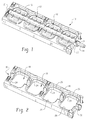
- Low-leakage air valve assembly 10 is intended for use preferably with a plastic air intake manifold with an active runner system.
- the air valve shortens the air flow path at high RPMs to optimize engine torque.
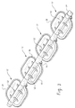
- Low-leakage air valve assembly 10 comprises a plurality of butterfly valves 12 selectively positioned on shaft 14. Shaft 14 and butterfly valves 12 are nestingly received within air valve manifold 16.
- Air valve manifold 16 includes a plurality of ports 18 corresponding to the spacing of the plurality of butterfly valves 12.
- Channel 20 in the air valve manifold 16 receives the shaft 14 and allows butterfly valves 12 to be seated within the ports 18.
- Channel 20 extends in axial alignment across valve manifold 16 as best shown in FIG. 2.
- valve manifold 16 includes a boss 22 which is an extension of channel 20 for receiving shaft 14.
- a bushing 21 made of oil impregnated bronze powdered metal or any other suitable material may be employed within boss 22 and at the opposite end of shaft 14 to better retain shaft 14 within channel 20.
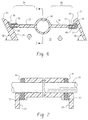
- ports 18 and side walls 24 of valve manifold 16 are at a slight angle, ⁇ , relative to normal (as shown in FIG. 6) of about 10° to about 65°, and preferably at 65°. This angle is provided for packaging or insertion in the assembly.
- ports 18 of the valve manifold 16 are substantially square or rectangular in shape and contoured radially about their upper edge to maximize air flow in the available space. Their sides are radiused and include a shelf 26 on one side or half of the port 18 and a shoulder 28 on the other side or half of the port as shown in FIGS. 2 and 6. Shelf 26 is situated at a depth of preferably approximately one-third to one-half the depth of the port 18 and is contoured around channel 20 where it terminates at a point about midway therein. Of course, any depth sufficient to seat the valve 12 may be employed.
- Valve manifold 16 is constructed to receive shaft 14 with preferably four butterfly valves therein and allows shaft to partially rotate therein.
- the valve assembly 10 in accordance with the present invention may use as few as one valve 12 or as many as desired.
- Shaft 14 is constructed to rotate sufficiently within channel 20 so that the port 18 is open to its fullest extent possible.
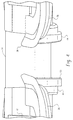
- Each butterfly valve 12 has a passage 30 axially situated therein for receiving shaft 14.
- Shaft 14 extending through passage 30 divides each butterfly valve 12 so as to define a first wing 32 and a second wing 34.
- First elastic sealing means 36 which is preferably a rubber material like silicone or HNBR (hydrogenated nitrile butadiene rubber) is mounted about the periphery of the first wing 32.
- the first elastic sealing means 36 includes a projecting lip 38 which is constructed to seal against contoured side wall 24 of port 18 in the valve manifold 16 when acted upon by a vacuum generally indicated as V to show the vacuum side produced in the ordinary course of an internal combustion engine's cycle. The vacuum assists the seal of the projecting lip 38 against side wall 24 when the vacuum draws the lip 38 down, as indicated by the arrow V, against shelf 26 as best seen in FIG. 6.
- the second wing 34 of the butterfly valve 12 has a second elastic sealing means 40 which is preferably a rubber material like silicone or HNBR mounted thereon about its periphery.
- the second elastic sealing means 40 includes a beam portion 42 which is constructed to press upward against the shoulder 28 of port 18 in the valve manifold 16. As vacuum V pulls downward on both wings, second wind 34 has a tendency to push upwards in the direction of arrow A due to angular rotation about shaft 14, but since the first wing has a larger area, then a net torque is created.
- Beam portion 42 is preferably a substantially flat portion so as to produce an increased sealing force when acted upon as previously described by the vacuum and applied torque.
- a third elastic sealing means 44 which is also preferably a rubber material like silicone or HNBR is axially positioned at each side of the passage 30 in the butterfly valve 12 on shaft 14.
- the third elastic sealing means 44 is positioned around approximately one-half of the lower side or underside of the shaft 14.
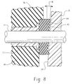
- the third elastic sealing means 44 includes an angled sealing surface 46 which provides a slight incline to generate decreasing compression of the sliding seal as the butterfly valve 12 rotates in the port 18 until a clearance ultimately exists.
- the angled sealing surface 46 is at a slight included angle as shown in FIG. 8 ranging from about 70° to about 89°, and more preferably at about 86° to the shaft. In this manner in the preferred embodiment, the sealing surface is not 90° to the shaft. This reduces friction and wear.
- the preferred embodiment of the butterfly valve 12 defines a first area 54 by the first sealing surface which is the first wing 32 and first elastic sealing means 36 including projecting lip 38 to be larger than a second area 56 defined by the second sealing surface which is the second wing 34 and second elastic sealing means 40, as illustrated in FIG. 5.
- This provides a net torque which increases the sealing force on the second sealing surface 56 or zone. While this torque does nothing for the first sealing surface 54 or zone as the rotation of the valve 12 is stopped, it does increase the sealing force in the second sealing zone 56.
- This provides the advantage of reducing the actuator torque requirement.
- the butterfly valve assembly 10 of the present invention cannot provide a shaft sealing surface through 360° rotation around the shaft. In other words, shaft 14 provides limited rotational movement, but sufficient to allow air to flow fully through ports 18.
- the present invention provides the advantage for a multiple valve application as well as allowing the valves to be assembled onto the shaft, and then assembled into the valve manifold 16 for a drop-in configuration.
- Additional apertures may be provided in the walls of the valve manifold 16 for receiving fasteners in accommodating the drop-in configuration to readily mount into an existing air intake assembly.
- a ridge 48 or even a plurality of ridges 48 of a rubber material or any other suitable elastomer are positioned on the substantially flat portion of the beam portion 42 of the second elastic sealing means 40.
- These ridges 48 may be progressively structured in height to reduce the pressure each bead must seal against shoulder 28.
- a ridge 50 or a plurality of ridges 50 may be positioned on the angled sealing surface 46 on each side of butterfly valve 12 to locally increase the sealing stresses. This results in a seal that works at lower torque, lower compression, and lower friction.
- valves 12 any number of valves or even a single valve may be either molded or assembled onto a shaft with keys and/or fasteners.
- the first, second, and third elastic sealing means can be applied thereafter.
- the elastic sealing means may be applied first to the butterfly valves 12 and then assembled on shaft 14 with fasteners or press-fit.
- the preferred embodiment of the present invention is particularly directed to plastic air intake manifolds with the valve manifold 16 being constructed of plastic and the butterfly valves 12 being of plastic with preferably rubber first, second, and third elastic sealing means, these items may be made from any material that provides the low-leakage feature of the present invention.
- reinforcement ribs 52 provided on both wings 32, 34 of the butterfly valve 12. Ribs 52 may be molded directly into the wings as the wings are formed. They may be formed by plastic injection molding, blow molding, or any other suitable manner.
- the first sealing zone is rather similar to any butterfly valve with the flexible projecting lip 38 providing a seal by contact with a wall of port 18 as illustrated in FIG. 6.
- Shelf 26 is an overtravel stop to assist in preventing damage to other seal 40. When acted upon with a vacuum, V, this increases the sealing force.
- the opposing or second wing 34 of butterfly valve 12 uses the smaller area and shorter second elastic sealing means 40 with its beam portion 42 to bend against shoulder 28 upon contact. This beam deflection compensates for any flatness issues and positional tolerances with respect to the valve manifold 16 and in particular the shoulder 28 therein.
- Ridge 48 on the beam portion 42 acts to concentrate the stress to achieve a seal with minimal applied torque since there is usually a limited quantity of torque available as actuation torque is often a function of cost.
- the torque is used to deflect the beam 42 and make up for the flatness and tolerance issues.
- the third sealing zone is between the butterfly valve 12 and the valve manifold 16 at the shaft 14 in channel 20.
- Other approaches in the past have used a bell-shaped, sliding seal, which increases friction and wear in this area.
- the design of the present invention does not employ a bell-shape nor does it require 360° sealing surfaces.
- the present invention employs a sliding seal with preferably a stress-concentrating bead 50 along the underside of the shaft only.
- the sealing surface is not 90° to the shaft, but rather at a slight included angle ⁇ (preferably around 86°).
- the slight angled sealing surface 46 of the present invention generates a decreasing compression of the sliding seal as the butterfly valve 12 rotates until a clearance ultimately exists. The only time the third sealing zone is in full compression is when the valve 12 is in the fully seated position or closed position. Thus, friction and wear are significantly reduced and the limited torque is not wasted on sliding friction.
- the preferred method is to insert mold plastic onto the shaft 14, then mold rubber onto the plastic.
- a suitable plastic material is a glass filled nylon with a 33% glass filled nylon 6 being preferred and the preferred rubber material has a durometer range from approximately 50 to 60 URO such as silicone with a 50 URO preferred.
- a fluorosilicone material is also preferable, but is more expensive.
- Suitable materials allow for an operable temperature range of about - 40°C to about 150°C, and include, without limitation, a thermosetting material for the plastic.
- An alternative process may include a two step molding process where the plastic is a thermoplastic elastomer (also a suitable plastic material) molded on the shaft to form the plastic butterfly valves.
- the plastic is a thermoplastic elastomer (also a suitable plastic material) molded on the shaft to form the plastic butterfly valves.
- the temperature limits, hardness limits, fluid compatibility limits of the rubber material should be compatible with the thermoplastic elastomer.
- Still another alternative process is to assemble individual butterfly valves on a D-shaped shaft. If the butterfly valves are allowed to "float" or move in a somewhat limited manner axially, this can help tolerance issues involving positioning of the butterfly valves over the passages. In this manner, the valves would be self-centering. This reduces the amount of rubber material necessary for accommodating dimensional issues.
- the plastic material and rubber material can connect all of the butterfly valves as a thin film along the shaft. This is to prevent plastic flash (or plastic leakage during the molding process) due to a bent shaft or differences in the size of the shaft, and rubber flash.
- the present invention provides a low-leakage air valve suitable for use in variable intake system plastic manifold assemblies or in any air intake manifold.
- the present invention comprises a manifold 16 with at least one port 18.
- Port 18 includes a shelf 26 and shoulder 28 similar to that depicted in FIG. 2 and described above.
- the sealing means are provided as a minimum on the shelf 26 and shoulder 28.
- the sealing means is a rubber material similar to that previously described.
- the sealing means may be provided to any extent desired on the side walls 24 of port 18 from shelf 26 up to and including the radiused uppermost portion 25 of port 18 and in a similar manner around the shoulder 28 to its uppermost portion 27 as best shown in FIG. 6.
Applications Claiming Priority (2)
| Application Number | Priority Date | Filing Date | Title |
|---|---|---|---|
| US247409 | 1999-02-10 | ||
| US09/247,409 US6135418A (en) | 1999-02-10 | 1999-02-10 | Low-leakage air valve for variable air intake system |
Publications (3)
| Publication Number | Publication Date |
|---|---|
| EP1028238A2 true EP1028238A2 (fr) | 2000-08-16 |
| EP1028238A3 EP1028238A3 (fr) | 2001-01-03 |
| EP1028238B1 EP1028238B1 (fr) | 2005-04-06 |
Family
ID=22934817
Family Applications (1)
| Application Number | Title | Priority Date | Filing Date |
|---|---|---|---|
| EP00102000A Revoked EP1028238B1 (fr) | 1999-02-10 | 2000-02-02 | Clapet d'air à faible fuite pour système d'admission d'air à géométrie variable |
Country Status (9)
| Country | Link |
|---|---|
| US (1) | US6135418A (fr) |
| EP (1) | EP1028238B1 (fr) |
| JP (1) | JP2000234522A (fr) |
| KR (1) | KR20000071334A (fr) |
| AT (1) | ATE292749T1 (fr) |
| BR (1) | BR0000623A (fr) |
| CA (1) | CA2298205C (fr) |
| DE (1) | DE60019179T2 (fr) |
| ES (1) | ES2238947T3 (fr) |
Cited By (11)
| Publication number | Priority date | Publication date | Assignee | Title |
|---|---|---|---|---|
| EP1291504A3 (fr) * | 2001-09-05 | 2004-06-09 | Pierburg GmbH | Dispositif de volets de commande |
| WO2004048066A1 (fr) * | 2002-11-27 | 2004-06-10 | Siemens Aktiengesellschaft | Procede de production d'un clapet d'etranglement |
| EP1431545A2 (fr) * | 2002-12-17 | 2004-06-23 | Pierburg GmbH | Ensemble volets de commande |
| EP1486655A2 (fr) * | 2003-06-10 | 2004-12-15 | Mark IV Systemes Moteurs (Société Anonyme) | Dispositif à clapet et ensemble de regulation multivoies comprenant plusiers tels dispositifs |
| EP1498595A2 (fr) * | 2003-07-15 | 2005-01-19 | Eaton Corporation | Communication par impulsion de pression dans un système d'admission d'un moteur à combustion interne |
| GB2428081A (en) * | 2005-07-07 | 2007-01-17 | Siemens Ag | Flap valve mechanism for i.c. engine intake manifolds |
| EP1847738A1 (fr) * | 2006-04-18 | 2007-10-24 | Delphi Technologies, Inc. | Vanne de recirculation de gaz d'échappement pour un moteur à combustion interne |
| FR2918145A1 (fr) * | 2007-06-29 | 2009-01-02 | Valeo Sys Controle Moteur Sas | Vanne a volet pourvu d'une surface peripherique d'appui |
| EP1748167A3 (fr) * | 2005-07-04 | 2012-04-25 | Keihin Corporation | Dispositif de commande d'admission d'un moteur |
| EP2840250A1 (fr) * | 2013-08-19 | 2015-02-25 | Aisin Seiki Kabushiki Kaisha | Dispositif d'admission |
| EP1764492B2 (fr) † | 2005-09-20 | 2016-01-27 | Mahle International GmbH | Système d'alimentation d'air frais pour un moteur à combustion interne |
Families Citing this family (43)
| Publication number | Priority date | Publication date | Assignee | Title |
|---|---|---|---|---|
| FR2797931B1 (fr) * | 1999-08-31 | 2001-10-05 | Mark Iv Systemes Moteurs Sa | Dispositif de regulation de l'ecoulement dans une portion de conduit ou un passage et collecteur comprenant un tel dispositif |
| JP4300340B2 (ja) * | 2000-02-14 | 2009-07-22 | 株式会社デンソー | 通風路切替用ドア |
| FR2805878B1 (fr) * | 2000-03-01 | 2002-11-29 | Mark Iv Systemes Moteurs Sa | Dispositif de vanne a clapet et ensemble de regulation comportant de tels dispositifs |
| DE10126063B4 (de) * | 2001-05-28 | 2004-07-15 | Montaplast Gmbh | Klappenvorrichtung |
| KR100398253B1 (ko) * | 2001-06-27 | 2003-09-19 | 현대자동차주식회사 | 차량용 흡기 매니폴드의 소음저감구조 |
| JP3967127B2 (ja) * | 2001-12-19 | 2007-08-29 | 愛三工業株式会社 | 絞り弁 |
| KR100455314B1 (ko) * | 2002-03-05 | 2004-11-06 | 지엠대우오토앤테크놀로지주식회사 | 자동차 내연기관용 흡기매니폴드의 밸브구조 |
| US6880572B2 (en) * | 2002-04-15 | 2005-04-19 | Jenara Enterprises Ltd. | Exhaust gas control valve, apparatus and method of controlling exhaust gas flow |
| DE10217468A1 (de) * | 2002-04-19 | 2003-11-13 | Daimler Chrysler Ag | Vorrichtung und Verfahren zum Verschließen eines Strömungskanals sowie schwenkbare Absperr- und/oder Drosselklappe |
| KR20030096592A (ko) * | 2002-06-17 | 2003-12-31 | 현대자동차주식회사 | 가변흡기 시스템의 가변밸브 구조 |
| JP2004068794A (ja) * | 2002-08-02 | 2004-03-04 | Aisan Ind Co Ltd | 可変吸気バルブ |
| DE10237864A1 (de) * | 2002-08-19 | 2004-03-04 | Siemens Ag | Verfahren zum Abschliessen eines Drosselklappenstutzens |
| DE10240624A1 (de) * | 2002-09-03 | 2004-03-11 | Siemens Ag | Verfahren zum Abschließen eines Drosselklappenstutzens |
| JP2004204792A (ja) * | 2002-12-26 | 2004-07-22 | Aisan Ind Co Ltd | 内燃機関の吸気装置 |
| US7047936B2 (en) * | 2003-11-25 | 2006-05-23 | Aisan Kogyo Kabushiki Kaisha | Throttle bodies and methods of manufacturing such throttle bodies |
| DE112006000248B9 (de) * | 2005-01-25 | 2013-01-24 | Aisan Kogyo K.K. | Butterflydrosselventil für einen Verbrennungsmotor |
| WO2007030933A1 (fr) * | 2005-09-15 | 2007-03-22 | Litens Automotive Partnership | Collecteur d'admission ou d'echappement comportant des tuyaux de section variable |
| KR100716371B1 (ko) * | 2005-10-07 | 2007-05-11 | 현대자동차주식회사 | 가변흡기시스템의 밸브축 고정용 리테이너 |
| US20070119961A1 (en) * | 2005-11-30 | 2007-05-31 | Energy Plus Technologies, Llc | Electromagnetic frequency-controlled zoning and dampering system |
| DE102006033786A1 (de) * | 2006-07-19 | 2008-04-10 | Behr Gmbh & Co. Kg | Verfahren zur Herstellung von Hohlraumklappen und entsprechend hergestellte Hohlraumklappe |
| JP4457115B2 (ja) * | 2007-01-16 | 2010-04-28 | 日立オートモティブシステムズ株式会社 | バタフライ式弁装置 |
| JP5529364B2 (ja) * | 2007-01-26 | 2014-06-25 | 三菱重工業株式会社 | ダンパ、空気調和ユニットおよび車両用空気調和装置 |
| US7997247B2 (en) | 2007-06-04 | 2011-08-16 | Honda Motor Co., Ltd. | Engine intake control system |
| JP4719716B2 (ja) * | 2007-06-04 | 2011-07-06 | 本田技研工業株式会社 | エンジンの吸気制御装置 |
| JP5255922B2 (ja) * | 2008-06-23 | 2013-08-07 | 株式会社マーレ フィルターシステムズ | 内燃機関の可変吸気装置 |
| US8028677B2 (en) * | 2008-09-09 | 2011-10-04 | Mark Iv Systemes Moteurs Usa, Inc. | Assembly and method for controlling an air intake runner |
| FR2940367B1 (fr) * | 2008-12-22 | 2015-07-17 | Valeo Sys Controle Moteur Sas | Dispositif d'obturation de conduits d'admission d'air d'un moteur |
| US9586625B2 (en) * | 2009-07-21 | 2017-03-07 | Magna International Inc. | Vehicle engine compartment louver carrier with integrated ducting |
| KR101252207B1 (ko) * | 2011-07-05 | 2013-04-05 | 기아자동차주식회사 | 차량용 에어벤트 |
| WO2013137349A1 (fr) * | 2012-03-13 | 2013-09-19 | 日産自動車株式会社 | Dispositif d'admission variable pour moteur à combustion interne |
| US20140027660A1 (en) * | 2012-07-24 | 2014-01-30 | Field Controls, Llc | Low leakage flue damper |
| JP6252026B2 (ja) * | 2013-08-08 | 2017-12-27 | アイシン精機株式会社 | 吸気装置および吸気制御弁 |
| CN103438228B (zh) * | 2013-08-20 | 2015-09-09 | 山东莱德机械有限公司 | 自密封中线蝶阀 |
| KR101397573B1 (ko) | 2013-11-15 | 2014-05-20 | 인지컨트롤스 주식회사 | 내부삽입식 지지구조의 가변흡기밸브를 구비한 흡기매니폴드 |
| JP6281295B2 (ja) | 2014-01-27 | 2018-02-21 | アイシン精機株式会社 | 気流制御弁構造および吸気装置 |
| DE102015108914B4 (de) * | 2015-06-05 | 2022-11-10 | Dietrich Denker | Vorrichtung zur Absenkung von Strömungsgeräuschen |
| JP6554949B2 (ja) * | 2015-07-07 | 2019-08-07 | アイシン精機株式会社 | 吸気装置および弁体 |
| DE102015112717B4 (de) | 2015-08-03 | 2021-01-14 | Dietrich Denker | Vorrichtung zur Absenkung von Strömungsgeräuschen |
| DE102016203517A1 (de) * | 2016-03-03 | 2017-09-07 | Mahle International Gmbh | Frischluftzuführungseinrichtung für eine Brennkraftmaschine eines Kraftfahrzeugs |
| JP6825310B2 (ja) * | 2016-11-07 | 2021-02-03 | アイシン精機株式会社 | 吸気装置および弁体の製造方法 |
| JP6881751B2 (ja) * | 2017-07-28 | 2021-06-02 | 株式会社テージーケー | バタフライバルブ |
| CN107606189A (zh) * | 2017-10-31 | 2018-01-19 | 普雷沃流体控制科技(芜湖)有限公司 | 一种环保火化机高温烟气处理用蝶阀 |
| FR3121966A1 (fr) * | 2021-04-16 | 2022-10-21 | Faurecia Systemes D'echappement | Vanne d’échappement silencieuse |
Citations (1)
| Publication number | Priority date | Publication date | Assignee | Title |
|---|---|---|---|---|
| US5454357A (en) | 1994-12-12 | 1995-10-03 | General Motors Corporation | Slide port valve for an internal combustion engine |
Family Cites Families (20)
| Publication number | Priority date | Publication date | Assignee | Title |
|---|---|---|---|---|
| US3693650A (en) * | 1970-08-12 | 1972-09-26 | Ferry Cap & Set Screw Co | Valve device and anti-pollution system employing the same |
| US3799132A (en) * | 1973-04-09 | 1974-03-26 | Ferry Cap Set Screw Co | Valve device and system employing the same |
| US3990676A (en) * | 1974-11-15 | 1976-11-09 | Brownstein Raymond G | Gasket and valve construction |
| US4253641A (en) * | 1978-12-07 | 1981-03-03 | Vanryck Theodore H | Butterfly valve and perimeter seal |
| FR2504638B1 (fr) * | 1981-04-27 | 1986-01-17 | Pont A Mousson | Vanne papillon a corps revetu |
| US4491106A (en) * | 1982-11-29 | 1985-01-01 | Morris George Q | Throttle configuration achieving high velocity channel at partial opening |
| FR2554539B1 (fr) * | 1983-11-07 | 1986-01-31 | Verdelet Alain | Vanne a papillon perfectionnee |
| JPS61103065A (ja) * | 1984-10-26 | 1986-05-21 | Akira Oshima | バタフライ形制水弁における弁体 |
| DE3643948A1 (de) * | 1986-12-22 | 1988-06-23 | Vdo Schindling | Drosselklappenstutzen fuer eine brennkraftmaschine |
| FR2621377B1 (fr) * | 1987-10-02 | 1989-12-01 | Abg Semca | Segment d'etancheite pour vanne a papillon |
| US5098064A (en) * | 1990-02-16 | 1992-03-24 | Siemens Automotive L.P. | Engine throttle blade sealing |
| EP0494344A1 (fr) * | 1991-01-09 | 1992-07-15 | Firma Carl Freudenberg | Système d'étanchéité pour la construction d'un papillon avec un axe massif |
| DE4329527A1 (de) * | 1993-09-02 | 1995-03-09 | Mann & Hummel Filter | Drosseleinrichtung |
| DE4402048A1 (de) * | 1994-01-25 | 1995-07-27 | Mann & Hummel Filter | Integriertes Ansaugsystem |
| DE4423370A1 (de) * | 1994-07-04 | 1996-01-11 | Bayerische Motoren Werke Ag | Drosselklappen-Stutzen für eine Brennkraftmaschine |
| GB9611484D0 (en) * | 1996-06-01 | 1996-08-07 | Wabco Automotive Uk | A butterfly valve |
| FR2767893B1 (fr) * | 1997-09-01 | 1999-10-29 | Gec Alsthom Sapag | Vanne papillon a manchette elastique d'etancheite |
| US5979870A (en) * | 1998-03-02 | 1999-11-09 | Tapco International, Inc. | Butterfly value with offset stem |
| US5979871A (en) * | 1998-03-30 | 1999-11-09 | Ford Motor Company | Clamshell throttle valve assembly |
| DE19819364B4 (de) * | 1998-04-30 | 2006-10-12 | Robert Bosch Gmbh | Drosselklappe |
-
1999
- 1999-02-10 US US09/247,409 patent/US6135418A/en not_active Expired - Fee Related
-
2000
- 2000-02-02 ES ES00102000T patent/ES2238947T3/es not_active Expired - Lifetime
- 2000-02-02 DE DE60019179T patent/DE60019179T2/de not_active Expired - Fee Related
- 2000-02-02 EP EP00102000A patent/EP1028238B1/fr not_active Revoked
- 2000-02-02 AT AT00102000T patent/ATE292749T1/de not_active IP Right Cessation
- 2000-02-07 KR KR1020000005608A patent/KR20000071334A/ko not_active Application Discontinuation
- 2000-02-08 CA CA002298205A patent/CA2298205C/fr not_active Expired - Fee Related
- 2000-02-09 BR BR0000623-8A patent/BR0000623A/pt not_active IP Right Cessation
- 2000-02-10 JP JP2000033187A patent/JP2000234522A/ja active Pending
Patent Citations (1)
| Publication number | Priority date | Publication date | Assignee | Title |
|---|---|---|---|---|
| US5454357A (en) | 1994-12-12 | 1995-10-03 | General Motors Corporation | Slide port valve for an internal combustion engine |
Cited By (18)
| Publication number | Priority date | Publication date | Assignee | Title |
|---|---|---|---|---|
| EP1291504A3 (fr) * | 2001-09-05 | 2004-06-09 | Pierburg GmbH | Dispositif de volets de commande |
| WO2004048066A1 (fr) * | 2002-11-27 | 2004-06-10 | Siemens Aktiengesellschaft | Procede de production d'un clapet d'etranglement |
| EP1431545A2 (fr) * | 2002-12-17 | 2004-06-23 | Pierburg GmbH | Ensemble volets de commande |
| EP1431545A3 (fr) * | 2002-12-17 | 2007-05-23 | Pierburg GmbH | Ensemble volets de commande |
| US7392826B2 (en) | 2003-06-10 | 2008-07-01 | Mark Iv Systems Moteurs Societe Anonyme | Valve device and multiport regulating assembly comprising a plurality of such devices |
| EP1486655A2 (fr) * | 2003-06-10 | 2004-12-15 | Mark IV Systemes Moteurs (Société Anonyme) | Dispositif à clapet et ensemble de regulation multivoies comprenant plusiers tels dispositifs |
| FR2856128A1 (fr) * | 2003-06-10 | 2004-12-17 | Mark Iv Systemes Moteurs Sa | Dispositif a clapet et ensemble de regulation multivoies comprenant plusieurs tels dispositifs |
| EP1486655A3 (fr) * | 2003-06-10 | 2005-07-06 | Mark IV Systemes Moteurs (Société Anonyme) | Dispositif à clapet et ensemble de regulation multivoies comprenant plusiers tels dispositifs |
| EP1498595A2 (fr) * | 2003-07-15 | 2005-01-19 | Eaton Corporation | Communication par impulsion de pression dans un système d'admission d'un moteur à combustion interne |
| EP1498595A3 (fr) * | 2003-07-15 | 2005-08-24 | Eaton Corporation | Communication par impulsion de pression dans un système d'admission d'un moteur à combustion interne |
| EP1748167A3 (fr) * | 2005-07-04 | 2012-04-25 | Keihin Corporation | Dispositif de commande d'admission d'un moteur |
| GB2428081A (en) * | 2005-07-07 | 2007-01-17 | Siemens Ag | Flap valve mechanism for i.c. engine intake manifolds |
| GB2428081B (en) * | 2005-07-07 | 2010-04-07 | Siemens Ag | Flap Mechanism For Intake Manifolds And Its Production |
| EP1764492B2 (fr) † | 2005-09-20 | 2016-01-27 | Mahle International GmbH | Système d'alimentation d'air frais pour un moteur à combustion interne |
| EP1847738A1 (fr) * | 2006-04-18 | 2007-10-24 | Delphi Technologies, Inc. | Vanne de recirculation de gaz d'échappement pour un moteur à combustion interne |
| FR2918145A1 (fr) * | 2007-06-29 | 2009-01-02 | Valeo Sys Controle Moteur Sas | Vanne a volet pourvu d'une surface peripherique d'appui |
| EP2840250A1 (fr) * | 2013-08-19 | 2015-02-25 | Aisin Seiki Kabushiki Kaisha | Dispositif d'admission |
| US9399973B2 (en) | 2013-08-19 | 2016-07-26 | Aisen Seiki Kabushiki Kaisha | Intake device |
Also Published As
| Publication number | Publication date |
|---|---|
| KR20000071334A (ko) | 2000-11-25 |
| CA2298205A1 (fr) | 2000-08-10 |
| ATE292749T1 (de) | 2005-04-15 |
| EP1028238B1 (fr) | 2005-04-06 |
| DE60019179D1 (de) | 2005-05-12 |
| DE60019179T2 (de) | 2006-03-09 |
| EP1028238A3 (fr) | 2001-01-03 |
| CA2298205C (fr) | 2006-09-26 |
| ES2238947T3 (es) | 2005-09-16 |
| JP2000234522A (ja) | 2000-08-29 |
| BR0000623A (pt) | 2000-09-05 |
| US6135418A (en) | 2000-10-24 |
Similar Documents
| Publication | Publication Date | Title |
|---|---|---|
| US6135418A (en) | Low-leakage air valve for variable air intake system | |
| US5696318A (en) | Air intake for an internal combustion engine | |
| JP2503140B2 (ja) | スロットル弁 | |
| EP2304284B1 (fr) | Vanne papillon, siège de vanne et dispositif de retenue de siège de vanne | |
| US20080223450A1 (en) | Flow control valves | |
| US6796280B2 (en) | Intake air control valve | |
| EP1486655B1 (fr) | Dispositif à clapet et ensemble de regulation multivoies comprenant plusiers tels dispositifs | |
| US11169549B2 (en) | Unit for the regulation or control of a fluid pressure | |
| US6742496B2 (en) | Butterfly valve | |
| JP2001520356A (ja) | シールエレメント | |
| CN106907278B (zh) | 充量运动控制阀密封件及其组装方法 | |
| US5329903A (en) | Pivotable joint | |
| US6478011B2 (en) | Air intake device for an internal combustion engine | |
| JP3089221B2 (ja) | バタフライ弁の軸封装置 | |
| KR100602749B1 (ko) | 스위치 요소를 갖는 흡입관 | |
| KR101114085B1 (ko) | 가변 흡기 매니폴드의 밸브 샤프트 지지구조 | |
| CA1047019A (fr) | Soupape de regulation de fluides | |
| US20040000657A1 (en) | Device and method for closing a flow duct and pivotable shut-off and/or throttle valve | |
| JP2003003920A (ja) | 内燃機関の吸気装置 | |
| JPH088248Y2 (ja) | 吸気制御バルブ装置 | |
| JP2536531Y2 (ja) | 摺動絞り弁型気化器 | |
| JPH061938U (ja) | バタフライバルブ | |
| JPH0942218A (ja) | シリンダ型アクチュエータ | |
| JPH0579362A (ja) | スロツトルボデイ |
Legal Events
| Date | Code | Title | Description |
|---|---|---|---|
| PUAI | Public reference made under article 153(3) epc to a published international application that has entered the european phase |
Free format text: ORIGINAL CODE: 0009012 |
|
| AK | Designated contracting states |
Kind code of ref document: A2 Designated state(s): AT BE CH CY DE DK ES FI FR GB GR IE IT LI LU MC NL PT SE |
|
| AX | Request for extension of the european patent |
Free format text: AL;LT;LV;MK;RO;SI |
|
| PUAL | Search report despatched |
Free format text: ORIGINAL CODE: 0009013 |
|
| AK | Designated contracting states |
Kind code of ref document: A3 Designated state(s): AT BE CH CY DE DK ES FI FR GB GR IE IT LI LU MC NL PT SE |
|
| AX | Request for extension of the european patent |
Free format text: AL;LT;LV;MK;RO;SI |
|
| 17P | Request for examination filed |
Effective date: 20001213 |
|
| AKX | Designation fees paid |
Free format text: AT BE CH CY DE DK ES FI FR GB GR IE IT LI LU MC NL PT SE |
|
| 17Q | First examination report despatched |
Effective date: 20031209 |
|
| GRAP | Despatch of communication of intention to grant a patent |
Free format text: ORIGINAL CODE: EPIDOSNIGR1 |
|
| GRAS | Grant fee paid |
Free format text: ORIGINAL CODE: EPIDOSNIGR3 |
|
| GRAA | (expected) grant |
Free format text: ORIGINAL CODE: 0009210 |
|
| AK | Designated contracting states |
Kind code of ref document: B1 Designated state(s): AT BE CH CY DE DK ES FI FR GB GR IE IT LI LU MC NL PT SE |
|
| PG25 | Lapsed in a contracting state [announced via postgrant information from national office to epo] |
Ref country code: LI Free format text: LAPSE BECAUSE OF FAILURE TO SUBMIT A TRANSLATION OF THE DESCRIPTION OR TO PAY THE FEE WITHIN THE PRESCRIBED TIME-LIMIT Effective date: 20050406 Ref country code: BE Free format text: LAPSE BECAUSE OF FAILURE TO SUBMIT A TRANSLATION OF THE DESCRIPTION OR TO PAY THE FEE WITHIN THE PRESCRIBED TIME-LIMIT Effective date: 20050406 Ref country code: FI Free format text: LAPSE BECAUSE OF FAILURE TO SUBMIT A TRANSLATION OF THE DESCRIPTION OR TO PAY THE FEE WITHIN THE PRESCRIBED TIME-LIMIT Effective date: 20050406 Ref country code: CH Free format text: LAPSE BECAUSE OF FAILURE TO SUBMIT A TRANSLATION OF THE DESCRIPTION OR TO PAY THE FEE WITHIN THE PRESCRIBED TIME-LIMIT Effective date: 20050406 Ref country code: AT Free format text: LAPSE BECAUSE OF FAILURE TO SUBMIT A TRANSLATION OF THE DESCRIPTION OR TO PAY THE FEE WITHIN THE PRESCRIBED TIME-LIMIT Effective date: 20050406 |
|
| REG | Reference to a national code |
Ref country code: GB Ref legal event code: FG4D |
|
| REG | Reference to a national code |
Ref country code: SE Ref legal event code: TRGR |
|
| REG | Reference to a national code |
Ref country code: CH Ref legal event code: EP |
|
| REG | Reference to a national code |
Ref country code: IE Ref legal event code: FG4D |
|
| REF | Corresponds to: |
Ref document number: 60019179 Country of ref document: DE Date of ref document: 20050512 Kind code of ref document: P |
|
| PG25 | Lapsed in a contracting state [announced via postgrant information from national office to epo] |
Ref country code: DK Free format text: LAPSE BECAUSE OF FAILURE TO SUBMIT A TRANSLATION OF THE DESCRIPTION OR TO PAY THE FEE WITHIN THE PRESCRIBED TIME-LIMIT Effective date: 20050706 Ref country code: GR Free format text: LAPSE BECAUSE OF FAILURE TO SUBMIT A TRANSLATION OF THE DESCRIPTION OR TO PAY THE FEE WITHIN THE PRESCRIBED TIME-LIMIT Effective date: 20050706 |
|
| PG25 | Lapsed in a contracting state [announced via postgrant information from national office to epo] |
Ref country code: PT Free format text: LAPSE BECAUSE OF FAILURE TO SUBMIT A TRANSLATION OF THE DESCRIPTION OR TO PAY THE FEE WITHIN THE PRESCRIBED TIME-LIMIT Effective date: 20050908 |
|
| REG | Reference to a national code |
Ref country code: ES Ref legal event code: FG2A Ref document number: 2238947 Country of ref document: ES Kind code of ref document: T3 |
|
| REG | Reference to a national code |
Ref country code: CH Ref legal event code: PL |
|
| PLBI | Opposition filed |
Free format text: ORIGINAL CODE: 0009260 |
|
| ET | Fr: translation filed | ||
| PGFP | Annual fee paid to national office [announced via postgrant information from national office to epo] |
Ref country code: NL Payment date: 20060109 Year of fee payment: 7 |
|
| PG25 | Lapsed in a contracting state [announced via postgrant information from national office to epo] |
Ref country code: IE Free format text: LAPSE BECAUSE OF NON-PAYMENT OF DUE FEES Effective date: 20060202 |
|
| PGFP | Annual fee paid to national office [announced via postgrant information from national office to epo] |
Ref country code: FR Payment date: 20060202 Year of fee payment: 7 |
|
| PGFP | Annual fee paid to national office [announced via postgrant information from national office to epo] |
Ref country code: SE Payment date: 20060203 Year of fee payment: 7 |
|
| 26 | Opposition filed |
Opponent name: PIERBURG GMBH PATENTABTEILUNG Effective date: 20051210 |
|
| PLAX | Notice of opposition and request to file observation + time limit sent |
Free format text: ORIGINAL CODE: EPIDOSNOBS2 |
|
| PG25 | Lapsed in a contracting state [announced via postgrant information from national office to epo] |
Ref country code: MC Free format text: LAPSE BECAUSE OF NON-PAYMENT OF DUE FEES Effective date: 20060228 Ref country code: LU Free format text: LAPSE BECAUSE OF NON-PAYMENT OF DUE FEES Effective date: 20060228 |
|
| PGFP | Annual fee paid to national office [announced via postgrant information from national office to epo] |
Ref country code: DE Payment date: 20060228 Year of fee payment: 7 Ref country code: IT Payment date: 20060228 Year of fee payment: 7 |
|
| NLR1 | Nl: opposition has been filed with the epo |
Opponent name: PIERBURG GMBH PATENTABTEILUNG |
|
| PLAF | Information modified related to communication of a notice of opposition and request to file observations + time limit |
Free format text: ORIGINAL CODE: EPIDOSCOBS2 |
|
| PLBB | Reply of patent proprietor to notice(s) of opposition received |
Free format text: ORIGINAL CODE: EPIDOSNOBS3 |
|
| REG | Reference to a national code |
Ref country code: IE Ref legal event code: MM4A |
|
| PG25 | Lapsed in a contracting state [announced via postgrant information from national office to epo] |
Ref country code: SE Free format text: LAPSE BECAUSE OF NON-PAYMENT OF DUE FEES Effective date: 20070203 |
|
| EUG | Se: european patent has lapsed | ||
| GBPC | Gb: european patent ceased through non-payment of renewal fee |
Effective date: 20070202 |
|
| NLV4 | Nl: lapsed or anulled due to non-payment of the annual fee |
Effective date: 20070901 |
|
| REG | Reference to a national code |
Ref country code: FR Ref legal event code: ST Effective date: 20071030 |
|
| RDAF | Communication despatched that patent is revoked |
Free format text: ORIGINAL CODE: EPIDOSNREV1 |
|
| PG25 | Lapsed in a contracting state [announced via postgrant information from national office to epo] |
Ref country code: DE Free format text: LAPSE BECAUSE OF NON-PAYMENT OF DUE FEES Effective date: 20070901 Ref country code: NL Free format text: LAPSE BECAUSE OF NON-PAYMENT OF DUE FEES Effective date: 20070901 |
|
| PG25 | Lapsed in a contracting state [announced via postgrant information from national office to epo] |
Ref country code: GB Free format text: LAPSE BECAUSE OF NON-PAYMENT OF DUE FEES Effective date: 20070202 Ref country code: FR Free format text: LAPSE BECAUSE OF NON-PAYMENT OF DUE FEES Effective date: 20070228 |
|
| RDAG | Patent revoked |
Free format text: ORIGINAL CODE: 0009271 |
|
| REG | Reference to a national code |
Ref country code: ES Ref legal event code: FD2A Effective date: 20070203 |
|
| STAA | Information on the status of an ep patent application or granted ep patent |
Free format text: STATUS: PATENT REVOKED |
|
| 27W | Patent revoked |
Effective date: 20080210 |
|
| PGFP | Annual fee paid to national office [announced via postgrant information from national office to epo] |
Ref country code: GB Payment date: 20060109 Year of fee payment: 7 |
|
| PG25 | Lapsed in a contracting state [announced via postgrant information from national office to epo] |
Ref country code: CY Free format text: LAPSE BECAUSE OF FAILURE TO SUBMIT A TRANSLATION OF THE DESCRIPTION OR TO PAY THE FEE WITHIN THE PRESCRIBED TIME-LIMIT Effective date: 20050406 |
|
| PG25 | Lapsed in a contracting state [announced via postgrant information from national office to epo] |
Ref country code: IT Free format text: LAPSE BECAUSE OF NON-PAYMENT OF DUE FEES Effective date: 20070202 |
|
| PG25 | Lapsed in a contracting state [announced via postgrant information from national office to epo] |
Ref country code: ES Free format text: LAPSE BECAUSE OF NON-PAYMENT OF DUE FEES Effective date: 20070203 |