EP1486655A2 - Dispositif à clapet et ensemble de regulation multivoies comprenant plusiers tels dispositifs - Google Patents
Dispositif à clapet et ensemble de regulation multivoies comprenant plusiers tels dispositifs Download PDFInfo
- Publication number
- EP1486655A2 EP1486655A2 EP04102626A EP04102626A EP1486655A2 EP 1486655 A2 EP1486655 A2 EP 1486655A2 EP 04102626 A EP04102626 A EP 04102626A EP 04102626 A EP04102626 A EP 04102626A EP 1486655 A2 EP1486655 A2 EP 1486655A2
- Authority
- EP
- European Patent Office
- Prior art keywords
- valve body
- support spindle
- conduit portion
- valve
- spindle
- Prior art date
- Legal status (The legal status is an assumption and is not a legal conclusion. Google has not performed a legal analysis and makes no representation as to the accuracy of the status listed.)
- Granted
Links
Images


Classifications
-
- F—MECHANICAL ENGINEERING; LIGHTING; HEATING; WEAPONS; BLASTING
- F02—COMBUSTION ENGINES; HOT-GAS OR COMBUSTION-PRODUCT ENGINE PLANTS
- F02M—SUPPLYING COMBUSTION ENGINES IN GENERAL WITH COMBUSTIBLE MIXTURES OR CONSTITUENTS THEREOF
- F02M35/00—Combustion-air cleaners, air intakes, intake silencers, or induction systems specially adapted for, or arranged on, internal-combustion engines
- F02M35/10—Air intakes; Induction systems
- F02M35/104—Intake manifolds
- F02M35/112—Intake manifolds for engines with cylinders all in one line
-
- F—MECHANICAL ENGINEERING; LIGHTING; HEATING; WEAPONS; BLASTING
- F02—COMBUSTION ENGINES; HOT-GAS OR COMBUSTION-PRODUCT ENGINE PLANTS
- F02D—CONTROLLING COMBUSTION ENGINES
- F02D9/00—Controlling engines by throttling air or fuel-and-air induction conduits or exhaust conduits
- F02D9/08—Throttle valves specially adapted therefor; Arrangements of such valves in conduits
- F02D9/10—Throttle valves specially adapted therefor; Arrangements of such valves in conduits having pivotally-mounted flaps
- F02D9/1005—Details of the flap
- F02D9/101—Special flap shapes, ribs, bores or the like
- F02D9/1015—Details of the edge of the flap, e.g. for lowering flow noise or improving flow sealing in closed flap position
-
- F—MECHANICAL ENGINEERING; LIGHTING; HEATING; WEAPONS; BLASTING
- F02—COMBUSTION ENGINES; HOT-GAS OR COMBUSTION-PRODUCT ENGINE PLANTS
- F02D—CONTROLLING COMBUSTION ENGINES
- F02D9/00—Controlling engines by throttling air or fuel-and-air induction conduits or exhaust conduits
- F02D9/08—Throttle valves specially adapted therefor; Arrangements of such valves in conduits
- F02D9/10—Throttle valves specially adapted therefor; Arrangements of such valves in conduits having pivotally-mounted flaps
- F02D9/1035—Details of the valve housing
- F02D9/104—Shaping of the flow path in the vicinity of the flap, e.g. having inserts in the housing
- F02D9/1045—Shaping of the flow path in the vicinity of the flap, e.g. having inserts in the housing for sealing of the flow in closed flap position, e.g. the housing forming a valve seat
-
- F—MECHANICAL ENGINEERING; LIGHTING; HEATING; WEAPONS; BLASTING
- F02—COMBUSTION ENGINES; HOT-GAS OR COMBUSTION-PRODUCT ENGINE PLANTS
- F02D—CONTROLLING COMBUSTION ENGINES
- F02D9/00—Controlling engines by throttling air or fuel-and-air induction conduits or exhaust conduits
- F02D9/08—Throttle valves specially adapted therefor; Arrangements of such valves in conduits
- F02D9/10—Throttle valves specially adapted therefor; Arrangements of such valves in conduits having pivotally-mounted flaps
- F02D9/109—Throttle valves specially adapted therefor; Arrangements of such valves in conduits having pivotally-mounted flaps having two or more flaps
-
- F—MECHANICAL ENGINEERING; LIGHTING; HEATING; WEAPONS; BLASTING
- F02—COMBUSTION ENGINES; HOT-GAS OR COMBUSTION-PRODUCT ENGINE PLANTS
- F02M—SUPPLYING COMBUSTION ENGINES IN GENERAL WITH COMBUSTIBLE MIXTURES OR CONSTITUENTS THEREOF
- F02M35/00—Combustion-air cleaners, air intakes, intake silencers, or induction systems specially adapted for, or arranged on, internal-combustion engines
- F02M35/10—Air intakes; Induction systems
- F02M35/10242—Devices or means connected to or integrated into air intakes; Air intakes combined with other engine or vehicle parts
- F02M35/10255—Arrangements of valves; Multi-way valves
-
- Y—GENERAL TAGGING OF NEW TECHNOLOGICAL DEVELOPMENTS; GENERAL TAGGING OF CROSS-SECTIONAL TECHNOLOGIES SPANNING OVER SEVERAL SECTIONS OF THE IPC; TECHNICAL SUBJECTS COVERED BY FORMER USPC CROSS-REFERENCE ART COLLECTIONS [XRACs] AND DIGESTS
- Y10—TECHNICAL SUBJECTS COVERED BY FORMER USPC
- Y10T—TECHNICAL SUBJECTS COVERED BY FORMER US CLASSIFICATION
- Y10T137/00—Fluid handling
- Y10T137/8593—Systems
- Y10T137/87265—Dividing into parallel flow paths with recombining
- Y10T137/8741—With common operator
- Y10T137/87442—Rotary valve
- Y10T137/87467—Axes of rotation parallel
- Y10T137/87475—Adjacent plate valves always parallel
-
- Y—GENERAL TAGGING OF NEW TECHNOLOGICAL DEVELOPMENTS; GENERAL TAGGING OF CROSS-SECTIONAL TECHNOLOGIES SPANNING OVER SEVERAL SECTIONS OF THE IPC; TECHNICAL SUBJECTS COVERED BY FORMER USPC CROSS-REFERENCE ART COLLECTIONS [XRACs] AND DIGESTS
- Y10—TECHNICAL SUBJECTS COVERED BY FORMER USPC
- Y10T—TECHNICAL SUBJECTS COVERED BY FORMER US CLASSIFICATION
- Y10T137/00—Fluid handling
- Y10T137/8593—Systems
- Y10T137/87265—Dividing into parallel flow paths with recombining
- Y10T137/87523—Rotary valve
- Y10T137/87531—Butterfly valve
Definitions
- the present invention relates to the field of the control and regulation of the flow of fluids, particularly gaseous fluids, and in particular within the scope of air intake systems for internal combustion engines, for example with regard to intake manifolds or distributors.
- the subject of the present invention is a valve-type regulating device, a multiport regulating assembly comprising a plurality of such devices and a method of producing an intake manifold comprising such an assembly.
- valve devices are already known for regulating the flow rate or varying the flow of a fluid in a conduit, tube or the like.
- valve device in which the valve body, in the closure position, is supported on internal steps in the region of the passage receiving said device and the passage from the open state to the closed state of said device being obtained by limited pivoting of said valve body.
- the object of the present invention in particular is to overcome the aforementioned limitation.
- valve device for regulating a fluid, particularly gaseous fluids, in a conduit portion, comprising a valve body fixed to a support spindle extending transversely into said portion and mounted with the ability to rotate therein, said conduit portion comprising, on either side of said spindle, opposing internal steps forming two bearing surface portions for corresponding edge parts of said valve body in the closure position thereof, each step extending substantially over approximately half of the internal circumference of the conduit portion in the region of the mounting position of the support spindle and said steps advantageously being offset on either side of the plane perpendicular to the direction of circulation of fluid in said portion and containing said support spindle, in such a manner that the pivot angle of the valve body between its maximum open position and its closure position is less than 90°, the device being characterised in that the opposing edge parts of the plate-shaped valve body comprise deformable sealing means, for operation thereof in the closure position of said valve body, in the form of two flexible lips extending from said edge parts asymmetrically on either
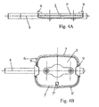
- valve device 1 for regulating a fluid, particularly a gaseous fluid, in a conduit portion 2, comprising a valve body 3 attached to a support spindle 4 extending transversely into said portion and mounted with the ability to rotate therein, said conduit portion 2 comprising, on either side of said spindle 4, opposing internal steps 5, 5' forming two bearing surface portions for corresponding edge parts 6, 6' of said valve body 3, in the closure position thereof, each step 5, 5' substantially extending over approximately half of the internal circumference of the conduit portion 2 in the region of the mounting position of the support spindle 4.
- said steps 5 and 5' are offset on either side of the perpendicular plane P in the direction D of circulation of the fluid in said portion 2 and containing said support spindle 4 in such a manner that the pivot angle of the valve body 3 between its maximum open position (minimal pressure loss caused by the valve body 3 - positioned along its edge in the direction D) and its closure position (stopper of the passage passing through the conduit portion 3) is less than 90°.
- the opposing edge parts 6, 6' of the plate-shaped valve body 3 comprise flexible sealing means 7, 7' for operation thereof in the closure position of said valve body 3, in the form of two flexible lips extending from said edge parts 6, 6' asymmetrically on either side of said valve body 3 and at an inclination to the plane of the valve body 3, a first lip 7 toward the exterior and the second lip 7' toward the interior.
- the two planar bearing surface portions 5 and 5' are contained in respective parallel planes, offset relative to one another in the direction D of circulation of the fluid and inclined relative to the plane P.
- the first lip 7 is elastically deformed by bending toward the exterior and the second lip 7' is elastically deformed by bending toward the interior, in the direction of the corresponding face of the valve body 3 by each being supported on a corresponding surface portion 5, 5' a continuation of the pivoting movement of the valve body 3, after a first contact of the lips 7, 7' with the bearing surface portions 5, 5', leading to an increase in the areas of said lips 7, 7' in contact with said portions and in the contact pressure.
- the valve body 3 consists of a plate 3' made of a rigid material covered, by overmoulding, with a flexible and elastic material 3" from which the two lips 7, 7' are also formed in one piece in the form of edges, one of which 7 extends laterally in an inclined manner toward the exterior from one of the faces of one of the edge parts 6 and the other of which 7' extends laterally in an inclined manner toward the interior from the opposite face of the other of the edge parts 6'.
- the flexible material 3" can form, in the region of the support spindle portions 4 situated between the lateral edges of the plate 3' and the areas of the internal wall opposite the conduit portion 2, sealing flanges 9 which take part in the stopper of the passage through said conduit portion 2, at least in the closure position of the valve body 3.
- the sealing flanges 9 only extend over half of the periphery of the aforementioned support spindle portions 4, their visible surfaces in the direction D of circulation of the fluid being at their greatest in the closure position of the valve body 3.
- Said sealing flanges 9 will produce, in particular, in the closure position of the valve body 3, a sealing of the passages defined by the lateral edges of said body 3, the steps 5 and 5' and the internal wall parts of the conduit portion 2, and in which the aforementioned support spindle portions 4 are situated.
- the device advantageously comprises an abutment means 8 preferably formed in one piece with the conduit portion 2, limiting the pivoting movement of the valve body 3 in the direction of sealing and defining a maximum closure position therefor, so as to avoid excessive deformation of the lips 7, 7'.
- This abutment means 8 can for example consist of a protruding pin or nose formed in the region of one of the steps 5, 5' (see in particular Figs. 2 and 5A) on which a local excess thickness 7" in the layer of flexible material 3" (see in particular Figs. 1, 3A, 3B and 4B) or possibly a localised deformation of the plate 3' is supported.
- At least one means 10, 10' can be provided to limit the pivoting of said body 3 in the opposite direction, advantageously in a rotational position located slightly beyond the maximum open position, for example in the form of a step or two opposing steps formed on the internal wall of said conduit portion 3, on which the lateral edges of the valve body 3 can be supported in the region of their faces opposite the faces carrying the lips 7 and 7'.
- the support spindle 4 can consist of a metal rod portion equipped with a flattened region 4' onto which is fixed, for example by riveting, by snap riveting or welding, the plate 3 in the form of a small metal plate, the flexible material 3" consisting of a silicone-based elastomer, for example of the type known by the name...
- the passage section of the conduit portion 2, at least in the region of the position for mounting the valve body 3/support spindle 4 assembly and the valve body 3 have a rectangular form with rounded corners.
- the valve device 1 consists of a module to be inserted or a preassembled cassette comprising, in addition to the valve body 3/support spindle 4 assembly, a structural body comprising a part 12 forming a stopper, equipped with at least one fixing flange 13 and extended by a perforated part 14 of a generally annular structure, providing at least the internal wall of a conduit portion 2 in the region of the mounting position of the valve body 3/support spindle 4 assembly and the steps forming seats 5, 5' for the edge parts 6, 6' of said valve body 3, said perforated part 14 comprising opposing guide bearings 15, 15' for the support spindle 4, one of said guide bearings also extending through the part 12 forming a stopper and the support spindle part 4 extending beyond the latter being fixed to a rotary-drive part or member 16, such as for example a small connecting rod (Fig. 1).
- the guide bearing situated in the part 12 forming a stopper could in particular comprise a seal with annular lips 12' creating an axial seal around the support spindle 4.
- the part 12 forming a stopper could comprise, in addition to two fixing flanges 13 in the form of lugs provided with apertures for the passage of fixing screws, also an abutment means 12" for the small connecting rod 16 in two extreme positions of rotation of the support spindle 4 (Figs. 1 and 5).
- the external faces of the parts 12 and 14 are preferably supported by a cylindrical surface with a slightly truncated extension, from the part 12 in the form of a stopper, sealing means 17, 18 being attached to said faces to ensure a circumferential peripheral seal in the region of said part 12 in the form of a stopper and on the external periphery of the annular part 14.
- sealing means 17, 18 consist of double-lipped seals attached by overmoulding and adjoining one another.
- the sealing means 17 and 18 can be provided with recesses forming special anchoring sites for said seals 17, 18.
- the present invention also relates, as shown in Fig. 6, to a multiport regulating assembly to control the circulation of a gaseous fluid in a plurality of conduits simultaneously, in particular in a plurality of tubes of an intake manifold in an internal combustion engine, characterised in that it consists of a plurality of valve devices 1 such as described above and shown in the accompanying figures, of which the respective valve body 3/support spindle 4 assemblies are controlled in position by a single control rod 19, functionally attached to an actuator 20, said devices 1 being mounted in an indexed manner in a sealed manner in transverse housings 21 produced in said conduits 22 with the support spindles 4 situated in a plane perpendicular to the directions of flow of the fluid in said conduits 22 and with the internal walls of the perforated parts 14 of the different devices 1 flush-mounted and adjoining the internal walls of the respective conduits receiving them.
- a multiport regulating assembly to control the circulation of a gaseous fluid in a plurality of conduits simultaneously, in particular in a plurality of tubes of
- the control rod 19 comprises a plurality of drive points 19', such as lugs, recesses, protuberances or the like, spaced along said rod and each engaging with a rotary-drive part 16 on a control spindle 4.
- control rod 19, the drive points 19', the actuator 20 and the parts 12 in the form of a stopper of the valve devices 1 could for example be produced in the manner described and shown in the French Patent No. 2 793 539 in the name of the applicant.
- the invention also relates to a method of producing an intake manifold comprising at least two tubes of which the circulation flow is controlled and equipped with a multiport regulating assembly such as described above (cf Fig. 6).
- This method essentially consists in producing at least one, and preferably a plurality of, manifold(s) provided with transverse housings 21 for receiving and mounting valve devices 1 of the aforementioned assembly, by means of the production method for mass-producing these manifolds, in measuring the deformations and play affecting the manifolds thus produced, in particular in the region of said transverse housings 21, in mass-producing the manifolds, the valve devices and control rods, the latter by taking into account the results of the aforementioned measures for the location of drive points 19' and finally, in mounting on each manifold the valve devices 1 and a corresponding control rod 19.
Applications Claiming Priority (2)
| Application Number | Priority Date | Filing Date | Title |
|---|---|---|---|
| FR0306930A FR2856128B1 (fr) | 2003-06-10 | 2003-06-10 | Dispositif a clapet et ensemble de regulation multivoies comprenant plusieurs tels dispositifs |
| FR0306930 | 2003-06-10 |
Publications (3)
| Publication Number | Publication Date |
|---|---|
| EP1486655A2 true EP1486655A2 (fr) | 2004-12-15 |
| EP1486655A3 EP1486655A3 (fr) | 2005-07-06 |
| EP1486655B1 EP1486655B1 (fr) | 2010-12-15 |
Family
ID=33186455
Family Applications (1)
| Application Number | Title | Priority Date | Filing Date |
|---|---|---|---|
| EP20040102626 Active EP1486655B1 (fr) | 2003-06-10 | 2004-06-09 | Dispositif à clapet et ensemble de regulation multivoies comprenant plusiers tels dispositifs |
Country Status (5)
| Country | Link |
|---|---|
| US (1) | US7392826B2 (fr) |
| EP (1) | EP1486655B1 (fr) |
| AT (1) | ATE491877T1 (fr) |
| DE (1) | DE602004030510D1 (fr) |
| FR (1) | FR2856128B1 (fr) |
Cited By (1)
| Publication number | Priority date | Publication date | Assignee | Title |
|---|---|---|---|---|
| FR2909744A1 (fr) * | 2006-12-06 | 2008-06-13 | Joint Francais | Clapet d'admission de gaz et conduite equipee d'un tel clapet. |
Families Citing this family (16)
| Publication number | Priority date | Publication date | Assignee | Title |
|---|---|---|---|---|
| FR2891886B1 (fr) | 2005-10-07 | 2010-04-02 | Mark Iv Systemes Moteurs Sa | Dispositif de regulation a clapet et collecteur d'admission comprenant au moins un tel dispositif |
| FR2905159B1 (fr) | 2007-09-14 | 2012-04-27 | Mark Iv Systemes Moteurs Sa | Dispositif de regulation a clapet et collecteur d'admission comprenant au moins un tel dispositif. |
| DE602008004647D1 (de) * | 2008-07-24 | 2011-03-03 | Magneti Marelli Spa | Saugrohr mit einem Drallsystems für einen Verbrennungsmotor |
| US9109708B2 (en) | 2009-08-04 | 2015-08-18 | Borgwarner Inc. | Engine breathing system valve and products including the same |
| JP5610201B2 (ja) * | 2010-06-17 | 2014-10-22 | アイシン精機株式会社 | 流体制御弁 |
| US20140027660A1 (en) * | 2012-07-24 | 2014-01-30 | Field Controls, Llc | Low leakage flue damper |
| DE102012110763B4 (de) * | 2012-11-09 | 2015-02-05 | Pierburg Gmbh | Klappenvorrichtung für eine Verbrennungskraftmaschine oder ein Elektrofahrzeug |
| DE102014112398B4 (de) * | 2014-08-28 | 2021-01-21 | BorgWarner Esslingen GmbH | Ventil für einen Abgasstrang einer Brennkraftmaschine |
| DE102015104287B4 (de) * | 2015-03-23 | 2018-02-01 | BorgWarner Esslingen GmbH | Ventil für einen Abgasstrang einer Brennkraftmaschine |
| US10012187B1 (en) * | 2017-01-05 | 2018-07-03 | Ford Global Technologies, Llc | Charge motion control valve |
| US10768031B2 (en) | 2018-01-17 | 2020-09-08 | Johnson Controls, Inc. | Air duct airflow sensor |
| US11448420B2 (en) | 2018-01-17 | 2022-09-20 | Johnson Controls, Inc. | Air duct damper |
| USD1014731S1 (en) | 2019-01-17 | 2024-02-13 | Johnson Controls Tyco IP Holdings LLP | Damper |
| NZ787344A (en) * | 2019-10-16 | 2022-07-29 | Creative Cosmetic Concepts Llc | Device for selectively storing and mixing first and second liquids |
| FR3121966A1 (fr) * | 2021-04-16 | 2022-10-21 | Faurecia Systemes D'echappement | Vanne d’échappement silencieuse |
| CN116105937B (zh) * | 2023-02-15 | 2024-04-30 | 东台市鑫航船用配件有限公司 | 一种用于阀体加工生产线的检测装置 |
Citations (5)
| Publication number | Priority date | Publication date | Assignee | Title |
|---|---|---|---|---|
| US5098064A (en) * | 1990-02-16 | 1992-03-24 | Siemens Automotive L.P. | Engine throttle blade sealing |
| JPH07279696A (ja) * | 1994-04-12 | 1995-10-27 | Mikuni Corp | スロットル弁 |
| DE19819364A1 (de) * | 1998-04-30 | 1999-11-04 | Bosch Gmbh Robert | Drosselklappe |
| EP1028238A2 (fr) * | 1999-02-10 | 2000-08-16 | Eaton Corporation | Clapet d'air à faible fuite pour système d'admission d'air à géométrie variable |
| WO2001020180A1 (fr) * | 1999-09-16 | 2001-03-22 | Montaplast Gmbh | Dispositif a paliers |
Family Cites Families (13)
| Publication number | Priority date | Publication date | Assignee | Title |
|---|---|---|---|---|
| US2816729A (en) * | 1953-02-26 | 1957-12-17 | Garrett Corp | Shut-off valve of the butterfly type |
| EP0494344A1 (fr) * | 1991-01-09 | 1992-07-15 | Firma Carl Freudenberg | Système d'étanchéité pour la construction d'un papillon avec un axe massif |
| US5681025A (en) * | 1995-01-20 | 1997-10-28 | Kohler Co. | Motor operated butterfly valve with a multi-function seal |
| DE19724549A1 (de) * | 1997-06-11 | 1998-12-17 | Xomox Int Gmbh | Armatur, insbesondere Regel- und Absperrklappe |
| US5979871A (en) * | 1998-03-30 | 1999-11-09 | Ford Motor Company | Clamshell throttle valve assembly |
| JP3712533B2 (ja) * | 1998-06-30 | 2005-11-02 | 愛三工業株式会社 | 内燃機関の吸気制御バルブ装置 |
| DE19848440A1 (de) * | 1998-10-21 | 2000-04-27 | Mann & Hummel Filter | Klappenmechanismus |
| DE19936456A1 (de) * | 1999-08-03 | 2001-02-08 | Mann & Hummel Filter | Ventil |
| HUP0202827A2 (en) * | 1999-08-24 | 2002-12-28 | Siemens Ag | Suction intake device for an internal combustion machine |
| FR2805878B1 (fr) * | 2000-03-01 | 2002-11-29 | Mark Iv Systemes Moteurs Sa | Dispositif de vanne a clapet et ensemble de regulation comportant de tels dispositifs |
| US6354267B1 (en) * | 2000-03-28 | 2002-03-12 | Borgwarner Inc. | Injection molded throttle body |
| JP3967127B2 (ja) * | 2001-12-19 | 2007-08-29 | 愛三工業株式会社 | 絞り弁 |
| US6793197B2 (en) * | 2003-01-30 | 2004-09-21 | Fisher Controls International, Inc. | Butterfly valve |
-
2003
- 2003-06-10 FR FR0306930A patent/FR2856128B1/fr not_active Expired - Fee Related
-
2004
- 2004-06-09 AT AT04102626T patent/ATE491877T1/de not_active IP Right Cessation
- 2004-06-09 EP EP20040102626 patent/EP1486655B1/fr active Active
- 2004-06-09 DE DE200460030510 patent/DE602004030510D1/de active Active
- 2004-06-10 US US10/865,396 patent/US7392826B2/en active Active
Patent Citations (5)
| Publication number | Priority date | Publication date | Assignee | Title |
|---|---|---|---|---|
| US5098064A (en) * | 1990-02-16 | 1992-03-24 | Siemens Automotive L.P. | Engine throttle blade sealing |
| JPH07279696A (ja) * | 1994-04-12 | 1995-10-27 | Mikuni Corp | スロットル弁 |
| DE19819364A1 (de) * | 1998-04-30 | 1999-11-04 | Bosch Gmbh Robert | Drosselklappe |
| EP1028238A2 (fr) * | 1999-02-10 | 2000-08-16 | Eaton Corporation | Clapet d'air à faible fuite pour système d'admission d'air à géométrie variable |
| WO2001020180A1 (fr) * | 1999-09-16 | 2001-03-22 | Montaplast Gmbh | Dispositif a paliers |
Non-Patent Citations (1)
| Title |
|---|
| PATENT ABSTRACTS OF JAPAN vol. 1996, no. 02, 29 February 1996 (1996-02-29) & JP 07 279696 A (MIKUNI CORP), 27 October 1995 (1995-10-27) * |
Cited By (1)
| Publication number | Priority date | Publication date | Assignee | Title |
|---|---|---|---|---|
| FR2909744A1 (fr) * | 2006-12-06 | 2008-06-13 | Joint Francais | Clapet d'admission de gaz et conduite equipee d'un tel clapet. |
Also Published As
| Publication number | Publication date |
|---|---|
| DE602004030510D1 (de) | 2011-01-27 |
| EP1486655A3 (fr) | 2005-07-06 |
| US7392826B2 (en) | 2008-07-01 |
| ATE491877T1 (de) | 2011-01-15 |
| US20050016602A1 (en) | 2005-01-27 |
| EP1486655B1 (fr) | 2010-12-15 |
| FR2856128B1 (fr) | 2006-12-29 |
| FR2856128A1 (fr) | 2004-12-17 |
Similar Documents
| Publication | Publication Date | Title |
|---|---|---|
| US7392826B2 (en) | Valve device and multiport regulating assembly comprising a plurality of such devices | |
| US6135418A (en) | Low-leakage air valve for variable air intake system | |
| US6763802B1 (en) | Intake manifold valve system | |
| US5696318A (en) | Air intake for an internal combustion engine | |
| JPWO2006080273A1 (ja) | 内燃機関の蝶弁式絞り弁 | |
| JPH04308332A (ja) | スロットル弁 | |
| US20200182358A1 (en) | Valve assembly | |
| US20030209682A1 (en) | Valve | |
| US6908072B2 (en) | Variable flow control valves | |
| JP2000018055A (ja) | 内燃機関の吸気制御バルブ装置 | |
| EP1243775A2 (fr) | Coin pour un papillon | |
| JP7150624B2 (ja) | Egrバルブ | |
| US11781666B2 (en) | Control valve | |
| JP2006070720A (ja) | 流路制御弁装置 | |
| JP4539369B2 (ja) | 吸気制御装置 | |
| US20100108011A1 (en) | Intake device for internal combustion engines | |
| US6880807B2 (en) | Flap valve | |
| JP6273768B2 (ja) | 吸気制御弁および吸気装置 | |
| JP5063582B2 (ja) | 吸気モジュール | |
| JPH0674348A (ja) | 絞弁体 | |
| JPH0579362A (ja) | スロツトルボデイ | |
| JP3017495U (ja) | クロスジョイントシール | |
| JPH0798065A (ja) | 機関の補助空気制御弁 | |
| JPH0336755Y2 (fr) | ||
| JP2572973Y2 (ja) | 板状摺動絞り弁型気化器 |
Legal Events
| Date | Code | Title | Description |
|---|---|---|---|
| PUAI | Public reference made under article 153(3) epc to a published international application that has entered the european phase |
Free format text: ORIGINAL CODE: 0009012 |
|
| AK | Designated contracting states |
Kind code of ref document: A2 Designated state(s): AT BE BG CH CY CZ DE DK EE ES FI FR GB GR HU IE IT LI LU MC NL PL PT RO SE SI SK TR |
|
| AX | Request for extension of the european patent |
Extension state: AL HR LT LV MK |
|
| PUAL | Search report despatched |
Free format text: ORIGINAL CODE: 0009013 |
|
| AK | Designated contracting states |
Kind code of ref document: A3 Designated state(s): AT BE BG CH CY CZ DE DK EE ES FI FR GB GR HU IE IT LI LU MC NL PL PT RO SE SI SK TR |
|
| AX | Request for extension of the european patent |
Extension state: AL HR LT LV MK |
|
| 17P | Request for examination filed |
Effective date: 20060104 |
|
| AKX | Designation fees paid |
Designated state(s): AT BE BG CH CY CZ DE DK EE ES FI FR GB GR HU IE IT LI LU MC NL PL PT RO SE SI SK TR |
|
| GRAP | Despatch of communication of intention to grant a patent |
Free format text: ORIGINAL CODE: EPIDOSNIGR1 |
|
| GRAS | Grant fee paid |
Free format text: ORIGINAL CODE: EPIDOSNIGR3 |
|
| GRAA | (expected) grant |
Free format text: ORIGINAL CODE: 0009210 |
|
| RAP1 | Party data changed (applicant data changed or rights of an application transferred) |
Owner name: MARK IV SYSTEMES MOTEURS |
|
| AK | Designated contracting states |
Kind code of ref document: B1 Designated state(s): AT BE BG CH CY CZ DE DK EE ES FI FR GB GR HU IE IT LI LU MC NL PL PT RO SE SI SK TR |
|
| REG | Reference to a national code |
Ref country code: CH Ref legal event code: EP Ref country code: GB Ref legal event code: FG4D |
|
| REG | Reference to a national code |
Ref country code: IE Ref legal event code: FG4D |
|
| REF | Corresponds to: |
Ref document number: 602004030510 Country of ref document: DE Date of ref document: 20110127 Kind code of ref document: P |
|
| REG | Reference to a national code |
Ref country code: NL Ref legal event code: VDEP Effective date: 20101215 |
|
| PG25 | Lapsed in a contracting state [announced via postgrant information from national office to epo] |
Ref country code: SI Free format text: LAPSE BECAUSE OF FAILURE TO SUBMIT A TRANSLATION OF THE DESCRIPTION OR TO PAY THE FEE WITHIN THE PRESCRIBED TIME-LIMIT Effective date: 20101215 Ref country code: SE Free format text: LAPSE BECAUSE OF FAILURE TO SUBMIT A TRANSLATION OF THE DESCRIPTION OR TO PAY THE FEE WITHIN THE PRESCRIBED TIME-LIMIT Effective date: 20101215 Ref country code: AT Free format text: LAPSE BECAUSE OF FAILURE TO SUBMIT A TRANSLATION OF THE DESCRIPTION OR TO PAY THE FEE WITHIN THE PRESCRIBED TIME-LIMIT Effective date: 20101215 Ref country code: CY Free format text: LAPSE BECAUSE OF FAILURE TO SUBMIT A TRANSLATION OF THE DESCRIPTION OR TO PAY THE FEE WITHIN THE PRESCRIBED TIME-LIMIT Effective date: 20101215 Ref country code: BG Free format text: LAPSE BECAUSE OF FAILURE TO SUBMIT A TRANSLATION OF THE DESCRIPTION OR TO PAY THE FEE WITHIN THE PRESCRIBED TIME-LIMIT Effective date: 20110315 Ref country code: NL Free format text: LAPSE BECAUSE OF FAILURE TO SUBMIT A TRANSLATION OF THE DESCRIPTION OR TO PAY THE FEE WITHIN THE PRESCRIBED TIME-LIMIT Effective date: 20101215 Ref country code: FI Free format text: LAPSE BECAUSE OF FAILURE TO SUBMIT A TRANSLATION OF THE DESCRIPTION OR TO PAY THE FEE WITHIN THE PRESCRIBED TIME-LIMIT Effective date: 20101215 |
|
| PG25 | Lapsed in a contracting state [announced via postgrant information from national office to epo] |
Ref country code: PT Free format text: LAPSE BECAUSE OF FAILURE TO SUBMIT A TRANSLATION OF THE DESCRIPTION OR TO PAY THE FEE WITHIN THE PRESCRIBED TIME-LIMIT Effective date: 20110415 Ref country code: EE Free format text: LAPSE BECAUSE OF FAILURE TO SUBMIT A TRANSLATION OF THE DESCRIPTION OR TO PAY THE FEE WITHIN THE PRESCRIBED TIME-LIMIT Effective date: 20101215 Ref country code: CZ Free format text: LAPSE BECAUSE OF FAILURE TO SUBMIT A TRANSLATION OF THE DESCRIPTION OR TO PAY THE FEE WITHIN THE PRESCRIBED TIME-LIMIT Effective date: 20101215 Ref country code: BE Free format text: LAPSE BECAUSE OF FAILURE TO SUBMIT A TRANSLATION OF THE DESCRIPTION OR TO PAY THE FEE WITHIN THE PRESCRIBED TIME-LIMIT Effective date: 20101215 Ref country code: GR Free format text: LAPSE BECAUSE OF FAILURE TO SUBMIT A TRANSLATION OF THE DESCRIPTION OR TO PAY THE FEE WITHIN THE PRESCRIBED TIME-LIMIT Effective date: 20110316 Ref country code: ES Free format text: LAPSE BECAUSE OF FAILURE TO SUBMIT A TRANSLATION OF THE DESCRIPTION OR TO PAY THE FEE WITHIN THE PRESCRIBED TIME-LIMIT Effective date: 20110326 |
|
| PG25 | Lapsed in a contracting state [announced via postgrant information from national office to epo] |
Ref country code: SK Free format text: LAPSE BECAUSE OF FAILURE TO SUBMIT A TRANSLATION OF THE DESCRIPTION OR TO PAY THE FEE WITHIN THE PRESCRIBED TIME-LIMIT Effective date: 20101215 Ref country code: PL Free format text: LAPSE BECAUSE OF FAILURE TO SUBMIT A TRANSLATION OF THE DESCRIPTION OR TO PAY THE FEE WITHIN THE PRESCRIBED TIME-LIMIT Effective date: 20101215 Ref country code: RO Free format text: LAPSE BECAUSE OF FAILURE TO SUBMIT A TRANSLATION OF THE DESCRIPTION OR TO PAY THE FEE WITHIN THE PRESCRIBED TIME-LIMIT Effective date: 20101215 |
|
| PLBE | No opposition filed within time limit |
Free format text: ORIGINAL CODE: 0009261 |
|
| STAA | Information on the status of an ep patent application or granted ep patent |
Free format text: STATUS: NO OPPOSITION FILED WITHIN TIME LIMIT |
|
| PG25 | Lapsed in a contracting state [announced via postgrant information from national office to epo] |
Ref country code: DK Free format text: LAPSE BECAUSE OF FAILURE TO SUBMIT A TRANSLATION OF THE DESCRIPTION OR TO PAY THE FEE WITHIN THE PRESCRIBED TIME-LIMIT Effective date: 20101215 |
|
| 26N | No opposition filed |
Effective date: 20110916 |
|
| PG25 | Lapsed in a contracting state [announced via postgrant information from national office to epo] |
Ref country code: IT Free format text: LAPSE BECAUSE OF FAILURE TO SUBMIT A TRANSLATION OF THE DESCRIPTION OR TO PAY THE FEE WITHIN THE PRESCRIBED TIME-LIMIT Effective date: 20101215 |
|
| REG | Reference to a national code |
Ref country code: DE Ref legal event code: R097 Ref document number: 602004030510 Country of ref document: DE Effective date: 20110916 |
|
| REG | Reference to a national code |
Ref country code: CH Ref legal event code: PL |
|
| GBPC | Gb: european patent ceased through non-payment of renewal fee |
Effective date: 20110609 |
|
| REG | Reference to a national code |
Ref country code: IE Ref legal event code: MM4A |
|
| PG25 | Lapsed in a contracting state [announced via postgrant information from national office to epo] |
Ref country code: LI Free format text: LAPSE BECAUSE OF NON-PAYMENT OF DUE FEES Effective date: 20110630 Ref country code: IE Free format text: LAPSE BECAUSE OF NON-PAYMENT OF DUE FEES Effective date: 20110609 Ref country code: CH Free format text: LAPSE BECAUSE OF NON-PAYMENT OF DUE FEES Effective date: 20110630 |
|
| PG25 | Lapsed in a contracting state [announced via postgrant information from national office to epo] |
Ref country code: GB Free format text: LAPSE BECAUSE OF NON-PAYMENT OF DUE FEES Effective date: 20110609 |
|
| PGFP | Annual fee paid to national office [announced via postgrant information from national office to epo] |
Ref country code: FR Payment date: 20120511 Year of fee payment: 9 |
|
| PG25 | Lapsed in a contracting state [announced via postgrant information from national office to epo] |
Ref country code: MC Free format text: LAPSE BECAUSE OF NON-PAYMENT OF DUE FEES Effective date: 20110630 |
|
| PG25 | Lapsed in a contracting state [announced via postgrant information from national office to epo] |
Ref country code: LU Free format text: LAPSE BECAUSE OF NON-PAYMENT OF DUE FEES Effective date: 20110609 |
|
| PG25 | Lapsed in a contracting state [announced via postgrant information from national office to epo] |
Ref country code: TR Free format text: LAPSE BECAUSE OF FAILURE TO SUBMIT A TRANSLATION OF THE DESCRIPTION OR TO PAY THE FEE WITHIN THE PRESCRIBED TIME-LIMIT Effective date: 20101215 |
|
| PG25 | Lapsed in a contracting state [announced via postgrant information from national office to epo] |
Ref country code: HU Free format text: LAPSE BECAUSE OF FAILURE TO SUBMIT A TRANSLATION OF THE DESCRIPTION OR TO PAY THE FEE WITHIN THE PRESCRIBED TIME-LIMIT Effective date: 20101215 |
|
| REG | Reference to a national code |
Ref country code: FR Ref legal event code: ST Effective date: 20140228 |
|
| PG25 | Lapsed in a contracting state [announced via postgrant information from national office to epo] |
Ref country code: FR Free format text: LAPSE BECAUSE OF NON-PAYMENT OF DUE FEES Effective date: 20130701 |
|
| REG | Reference to a national code |
Ref country code: DE Ref legal event code: R082 Ref document number: 602004030510 Country of ref document: DE Representative=s name: GEITZ TRUCKENMUELLER LUCHT CHRIST PATENTANWAEL, DE Ref country code: DE Ref legal event code: R082 Ref document number: 602004030510 Country of ref document: DE Representative=s name: BRP RENAUD UND PARTNER MBB, DE Ref country code: DE Ref legal event code: R082 Ref document number: 602004030510 Country of ref document: DE Representative=s name: GEITZ TRUCKENMUELLER LUCHT, PATENTANWAELTE, DE Ref country code: DE Ref legal event code: R081 Ref document number: 602004030510 Country of ref document: DE Owner name: SYSTEMES MOTEURS, FR Free format text: FORMER OWNER: MARK IV SYSTEMES MOTEURS, LEVALLOIS PERRET, FR |
|
| REG | Reference to a national code |
Ref country code: DE Ref legal event code: R082 Ref document number: 602004030510 Country of ref document: DE Representative=s name: GEITZ TRUCKENMUELLER LUCHT CHRIST PATENTANWAEL, DE Ref country code: DE Ref legal event code: R082 Ref document number: 602004030510 Country of ref document: DE Representative=s name: GEITZ TRUCKENMUELLER LUCHT, PATENTANWAELTE, DE |
|
| PGFP | Annual fee paid to national office [announced via postgrant information from national office to epo] |
Ref country code: DE Payment date: 20230523 Year of fee payment: 20 |