EP1027511B1 - Dispositif de reglage d'inclinaison de surface de construction sur plot - Google Patents
Dispositif de reglage d'inclinaison de surface de construction sur plot Download PDFInfo
- Publication number
- EP1027511B1 EP1027511B1 EP19980952446 EP98952446A EP1027511B1 EP 1027511 B1 EP1027511 B1 EP 1027511B1 EP 19980952446 EP19980952446 EP 19980952446 EP 98952446 A EP98952446 A EP 98952446A EP 1027511 B1 EP1027511 B1 EP 1027511B1
- Authority
- EP
- European Patent Office
- Prior art keywords
- disc
- angle
- adjustment
- adjusting
- adjusting element
- Prior art date
- Legal status (The legal status is an assumption and is not a legal conclusion. Google has not performed a legal analysis and makes no representation as to the accuracy of the status listed.)
- Expired - Lifetime
Links
- 230000002093 peripheral effect Effects 0.000 claims description 10
- 230000000007 visual effect Effects 0.000 claims description 2
- 125000006850 spacer group Chemical group 0.000 description 35
- 238000010276 construction Methods 0.000 description 14
- 238000009434 installation Methods 0.000 description 8
- 239000000463 material Substances 0.000 description 6
- -1 polypropylene Polymers 0.000 description 4
- 239000004743 Polypropylene Substances 0.000 description 3
- HCHKCACWOHOZIP-UHFFFAOYSA-N Zinc Chemical compound [Zn] HCHKCACWOHOZIP-UHFFFAOYSA-N 0.000 description 3
- 239000004567 concrete Substances 0.000 description 3
- 229920001155 polypropylene Polymers 0.000 description 3
- 239000000126 substance Substances 0.000 description 3
- 239000011701 zinc Substances 0.000 description 3
- 229910052725 zinc Inorganic materials 0.000 description 3
- XEEYBQQBJWHFJM-UHFFFAOYSA-N Iron Chemical compound [Fe] XEEYBQQBJWHFJM-UHFFFAOYSA-N 0.000 description 2
- 229910000831 Steel Inorganic materials 0.000 description 2
- 230000000903 blocking effect Effects 0.000 description 2
- 239000003365 glass fiber Substances 0.000 description 2
- 238000002347 injection Methods 0.000 description 2
- 239000007924 injection Substances 0.000 description 2
- 239000007788 liquid Substances 0.000 description 2
- 238000000034 method Methods 0.000 description 2
- 239000004033 plastic Substances 0.000 description 2
- 229920003023 plastic Polymers 0.000 description 2
- 229920000728 polyester Polymers 0.000 description 2
- 238000009418 renovation Methods 0.000 description 2
- 229910001220 stainless steel Inorganic materials 0.000 description 2
- 239000010935 stainless steel Substances 0.000 description 2
- 239000010959 steel Substances 0.000 description 2
- XLYOFNOQVPJJNP-UHFFFAOYSA-N water Substances O XLYOFNOQVPJJNP-UHFFFAOYSA-N 0.000 description 2
- 229920002943 EPDM rubber Polymers 0.000 description 1
- 241001415961 Gaviidae Species 0.000 description 1
- 239000004793 Polystyrene Substances 0.000 description 1
- 239000000654 additive Substances 0.000 description 1
- 230000000996 additive effect Effects 0.000 description 1
- XAGFODPZIPBFFR-UHFFFAOYSA-N aluminium Chemical compound [Al] XAGFODPZIPBFFR-UHFFFAOYSA-N 0.000 description 1
- 229910052782 aluminium Inorganic materials 0.000 description 1
- 238000005266 casting Methods 0.000 description 1
- 235000019994 cava Nutrition 0.000 description 1
- 229920001577 copolymer Polymers 0.000 description 1
- 230000001419 dependent effect Effects 0.000 description 1
- 230000008030 elimination Effects 0.000 description 1
- 238000003379 elimination reaction Methods 0.000 description 1
- 239000003063 flame retardant Substances 0.000 description 1
- 229920001903 high density polyethylene Polymers 0.000 description 1
- 239000004700 high-density polyethylene Substances 0.000 description 1
- 229910052742 iron Inorganic materials 0.000 description 1
- 238000012423 maintenance Methods 0.000 description 1
- 230000014759 maintenance of location Effects 0.000 description 1
- 238000004519 manufacturing process Methods 0.000 description 1
- 239000000203 mixture Substances 0.000 description 1
- 239000003208 petroleum Substances 0.000 description 1
- 229920000515 polycarbonate Polymers 0.000 description 1
- 239000004417 polycarbonate Substances 0.000 description 1
- 229920002223 polystyrene Polymers 0.000 description 1
- 230000000750 progressive effect Effects 0.000 description 1
- 230000002787 reinforcement Effects 0.000 description 1
- 230000003014 reinforcing effect Effects 0.000 description 1
- 239000002689 soil Substances 0.000 description 1
- 238000009987 spinning Methods 0.000 description 1
- 239000000454 talc Substances 0.000 description 1
- 229910052623 talc Inorganic materials 0.000 description 1
- 239000002023 wood Substances 0.000 description 1
Images


Classifications
-
- E—FIXED CONSTRUCTIONS
- E04—BUILDING
- E04D—ROOF COVERINGS; SKY-LIGHTS; GUTTERS; ROOF-WORKING TOOLS
- E04D11/00—Roof covering, as far as not restricted to features covered by only one of groups E04D1/00 - E04D9/00; Roof covering in ways not provided for by groups E04D1/00 - E04D9/00, e.g. built-up roofs, elevated load-supporting roof coverings
- E04D11/005—Supports for elevated load-supporting roof coverings
- E04D11/007—Height-adjustable spacers
-
- E—FIXED CONSTRUCTIONS
- E04—BUILDING
- E04F—FINISHING WORK ON BUILDINGS, e.g. STAIRS, FLOORS
- E04F15/00—Flooring
- E04F15/02—Flooring or floor layers composed of a number of similar elements
- E04F15/02177—Floor elements for use at a specific location
- E04F15/02183—Floor elements for use at a specific location for outdoor use, e.g. in decks, patios, terraces, verandas or the like
-
- E—FIXED CONSTRUCTIONS
- E04—BUILDING
- E04F—FINISHING WORK ON BUILDINGS, e.g. STAIRS, FLOORS
- E04F15/00—Flooring
- E04F15/02—Flooring or floor layers composed of a number of similar elements
- E04F15/024—Sectional false floors, e.g. computer floors
- E04F15/02447—Supporting structures
- E04F15/02464—Height adjustable elements for supporting the panels or a panel-supporting framework
- E04F15/0247—Screw jacks
- E04F15/02482—Screw jacks with a variable angle between panel and support
-
- E—FIXED CONSTRUCTIONS
- E04—BUILDING
- E04F—FINISHING WORK ON BUILDINGS, e.g. STAIRS, FLOORS
- E04F15/00—Flooring
- E04F15/02—Flooring or floor layers composed of a number of similar elements
- E04F15/02044—Separate elements for fastening to an underlayer
- E04F2015/0205—Separate elements for fastening to an underlayer with load-supporting elongated furring elements between the flooring elements and the underlayer
- E04F2015/02055—Separate elements for fastening to an underlayer with load-supporting elongated furring elements between the flooring elements and the underlayer with additional supporting elements between furring elements and underlayer
- E04F2015/02061—Separate elements for fastening to an underlayer with load-supporting elongated furring elements between the flooring elements and the underlayer with additional supporting elements between furring elements and underlayer adjustable perpendicular to the underlayer
-
- E—FIXED CONSTRUCTIONS
- E04—BUILDING
- E04F—FINISHING WORK ON BUILDINGS, e.g. STAIRS, FLOORS
- E04F15/00—Flooring
- E04F15/02—Flooring or floor layers composed of a number of similar elements
- E04F15/02044—Separate elements for fastening to an underlayer
- E04F2015/02105—Separate elements for fastening to an underlayer without load-supporting elongated furring elements between the flooring elements and the underlayer
- E04F2015/02127—Separate elements for fastening to an underlayer without load-supporting elongated furring elements between the flooring elements and the underlayer adjustable perpendicular to the underlayer
Definitions
- the present invention relates to an adjustment device the inclination of a building surface.
- pads To obtain raised floors, it is known to use pads. However, when raised building surfaces are arranged for example on a terrace, these are arranged according to a plan horizontal, while the base soil, meanwhile, has a certain slope to allow the evacuation of rainwater and / or maintenance, etc.
- Document DE-A-37 09 017 discloses an adjustment device the inclination of a construction surface comprising slabs, the device comprising a stud head provided with a platform on which the tiles are laid. The rotation of the base relative to the head of the stud allows the height of the stud to be adjusted.
- the first problem with this device is that it has no indication of the value of the inclination nor of its direction and it is therefore necessary use a level to adjust the tilt value of the device and also for adjusting the direction of the inclination of said device.
- DE-A-37 09 017 Another problem with the device described in DE-A-37 09 017 is that it can no longer be adjusted in height after installation under slabs. Indeed, if you want to rotate the head of the stud, you must remove the tiles because these rest on the platform of the stud. If we rotate the base of DE-A-37 09 017, the height of the stud will be changed but also the inclination of the device since a first piece forming an integral part of the base rotates at the same time as the latter.
- GB-A-1 238 463 describes an adjustment device of a building surface in which the parts provided to adjust the tilt of the device are movable one relative to the other by pivoting. It is not possible to rotate continues these pieces. Pivoting does not allow adjustment end since the positions of the parts with respect to each other are predetermined and do not allow any other choice.
- the object of the present invention is to remedy these problems.
- a device is proposed as defined in independent claim 1 or 17.
- the device according to the present invention has indications of value and direction of the tilt. This allows fast and trouble-free work have to use a level.
- the parts allowing the adjustment of the height and tilt of the device performing a continuous rotation one with respect to the other and this independently of the stud on which they are arranged, the adjustment obtained is very fine, the use of shims becomes unnecessary and the setting can be changed even after installation slabs on the studs without having to dismantle everything.
- the head of the stud is adjustable horizontally by a very simple system without having to resort to imprecise shims while by ensuring a gain in labor.
- the invention consists in that, starting from a horizontal floor, one can create a sloping floor and thus create a new sloping roof on a existing roof.
- the device according to the present invention makes it possible to support and level horizontally slabs or raised floors or any other system installed on sloping ground in construction.
- This device placed on a sloping floor is adjustable in height and the head of the device is adjustable horizontally to straighten slopes going up to 5%, from 0 to 5cm / m, and even beyond.
- the possibility is offered of creating floors with slopes of up to 5 cm per meter and even beyond.
- the straightening of the stud horizontally is done at means of shims under the base of the block and shims on the head of the block.
- the spacer is placed on the head of the stud 13 and the horizontal adjustment is simplified.
- Radial and circular bars advantageously allow adjustment progressive angle by continuous mutual rotation of the two discs.
- the slope can be modified by simple rotation of the upper part without having to lift or remove the two spacer pieces and even without having to remove the stud under the slab.
- Yet another advantage of the device results the fact that we can position the stud in the direction of the slope and that we can thus immediately find the horizontality of the raised surface, thus providing a means of adjustment that is both reliable and rapid. Thanks to device, we know directly the value to be rectified, without one must seek, thereby providing immediate guidance.
- composition of the device depends on its use and it is manufactured by injection in black plastic material in polypropylene or polystyrene or high density polyethylene, or polycarbonate or polyester with or without glass fibers, with or without fire-retardant and self-extinguishing additive, and / or other materials synthetic. It can also be made by aluminum casting or made of steel and / or stainless steel.
- the values of the slope are indicated in the crown piece thus giving great convenience of use since it suffices to read the values indicated.
- the following device the invention can be adapted on a cylinder the upper part of which is plane.
- the device clips onto the stud and the assembly does not does not come off, which is very convenient on site. The two pieces upper and lower of the device are clipped and are therefore secured.
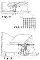
- Figure 1 illustrates a schematic plan view of a surface paved on studs.
- Figures 2A, 2B and 3 show perspective views schematics of a device according to the invention in its application General.
- FIGS 4 and 5 illustrate schematic views of the device according to the invention in applications respectively specific.
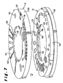
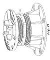
- Figure 6 shows a perspective view of a first mode for producing the device according to the invention.
- Figure 7 illustrates an exploded view of the two parts according to the figure 6.
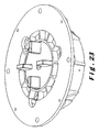
- Figure 8 illustrates a top view of the upper part of the device according to FIG. 7.
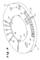
- Figure 9 illustrates a perspective view from below of the upper part according to the previous figure.
- Figure 10 illustrates a perspective view from above of the lower part of the device according to FIG. 7.
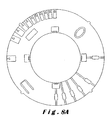
- Figure 11 illustrates a bottom view of the lower part of the device according to the previous figure.
- Figures 12 and 13 show enlarged views of two variants of a locking part of the above-mentioned assembly.
- Figures 14 to 17 each illustrate an overview of the device according to the invention associated with a pad according to an alternative embodiment respectively.
- Figures 18 to 21 illustrate different views of a variant of execution of the device according to FIGS. 15 to 17.
- Figures 22 to 24 illustrate different views of a variant additional execution of the device according to the invention.
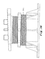
- Figure 2A illustrates a view of a set of several slabs placed on a double spacer 10 clipped onto cylinders 23 to fixed height serving as a support for slabs and placed on sloping ground 5.
- the surface 2 of the slabs 3 is horizontal thanks to the adjustment device double spacer 10.
- Figure 2B illustrates a view similar to Figure 2A with however arrangement of the double spacer 10 on an adjustable pad in height 1.
- FIG. 3 illustrates another view, similar to the previous ones, of the spacer 10 on an adjustable stud 1 supporting a slab 3 on a floor.
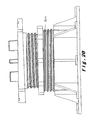
- Figures 4 and 5 each illustrate a view of the spacer 10 on adjustable studs 1 supporting beams 9 arranged in a chevron pattern a sloping floor 6 allowing the production of a floor 8 and respectively on a horizontal floor 6 allowing the realization of a roof in slope 7.
- Figure 6 illustrates a view of the assembly 10 consisting of two spacers 11, 12 clipped into each other in a position respective creating a certain slope, and more particularly in the example illustrated here at 5%, namely 5 cm / m in horizontal view from left to right in the drawing.
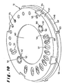
- Figure 8 shows marked locations consisting of rectangles 115 on which are written the various values ranging from 0 to 5 cm / m giving the direction of the slope to straighten or the slope to follow the arrow.
- a blocking hole 115 is provided on the part upper 11 to lock the lower part 12 by means of a pin 122.
- An oval window 114 in the upper part 11 is used to search on the lower part 12 the prescribed value of the initial slope given by rotation of the upper part 11 on the lower part 12.
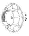
- lugs 117 are provided on the periphery of the central opening 179 of the upper part 11 for clipping the part 11 on the lower part.
- Figure 9 shows sixteen radial 118 bars of thickness different with regular growth between minimum and maximum thickness corresponding respectively to a setting of 0 to 5% or 0 to 5 cm / m by rotation of the upper disc 11 on the surface of the lower disc 12.
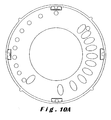
- Figure 10 shows reserved spaces 121 of reading which are provided on the lower disc 12, on which are written the prescribed values of the slope to be straightened ranging from 0 to 5 cm / m in the example described here.
- Two locking pins 122 are advantageously incorporated in the lower spacer part 12 as shown on the figure 11. They are detachable by rupture of the connecting bars 163.
- sixteen radial bars 126 of thickness different are provided here for the adjustment from 0 to 5% allowing the adjustment of the lower disc 12 by rotation on a cylindrical support 23 or a head cylindrical stud 13.
- the radial bars 116 have the same thicknesses respective that each of the radial bars 126 of FIG. 10.
- Clipping lugs 124 are provided around the periphery of the flange 147 of the skirt 141 for fixing the lower disc 12 on a cylindrical support 23 or on a cylindrical head of an adjustable stud 13.
- Eleven 125 receiving holes are provided in the room lower 12 for mutual locking of the two discs 11 and 12 from the stud to by means of one of the aforementioned pins 122.
- Outer bosses 123 are also provided on the periphery of said outer peripheral skirt thus ensuring a secure grip for the 360 ° lateral rotation of the assembly of the two integral parts on the cylindrical support 23 or on the head of the adjustable stud 13.
- Inclined guide elements 108 are provided on the inner periphery of the flange 147 of the skirt 141 of the lower part 12 to facilitate the installation of the spacer assembly 10 on a cylindrical support 23 or an adjustable stud head 13.
- the device when placed on a fixed cylindrical support or adjustable in height, allows to support and level horizontally raised slabs or floors or any other system laid on a slope especially in the field of construction.
- This device allows also to create, from a horizontal floor, a sloping surface by placing this device on a fixed or adjustable cylindrical support height.
- the tilt adjustment device of a construction surface 2 on stud 1 comprises an elevation element 1 of said construction surface 2 provided with a base surface 91 and vertex 92 forming a support surface for said construction surface. he comprises at least one adjustment and / or presetting element 11, respectively 12, which are intended to cooperate with each other.
- the first element 12 allows the establishment of the initial angle ⁇ of the inclination above while the second aforementioned second adjusting element 11 can be moved between an initial rest position and an operational position chosen by the user according to the slope to be imparted to said surface of construction.
- the second adjustment element 11 is orientable selectively with respect to the aforementioned first adjusting element 12, by so as to create a desired slope for the abovementioned construction surface 2, by positioning the aforementioned second adjustment element 11 relative to said first adjusting element 12 by rotation of said second element 11 by compared to the first 12.
- at least the second aforementioned element 11, 12 has adjustment means 119; 129 doing correspond, to each position of it relative to the first element supra 120, an adjustment angle.
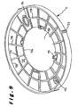
- Each aforementioned adjustment element 11; 12 consists of a disc with peripheral rim 131, 141 forming a skirt allowing a mutual interlocking of said adjustment parts 11, 12, advantageously by clipping.
- the aforementioned adjustment means 119, 129 include bars 118, 128 extending substantially radially over the surface inner 132, 142 of disc 11, 12.
- the radial bars 118, 128 have, so remarkable, a height varying almost linearly between a minimum value corresponding to the reference angle and a value maximum angle adjustment. In addition, they have a spacing substantially constant mutual.
- the aforementioned adjustment means 119, 129 include at minus one circular rib 139, 149 extending concentrically on the inner surface 132, 142 of the disc 11, 12.
- the circular rib mentioned above 139, 149 is provided midway between the outer edges 133, 143 and interiors 134, 144 of the discs.
- the height varies from practically linear between a minimum value corresponding to the reference angle and a maximum angle adjustment value.
- Each circular rib 139, 149 crosses the radial bars 118, 128 at almost right angles and at equal height, so that allow continuous rotation of one part 11 on the other 12.
- the double cylindrical spacer device 10 is formed of two discs 11, 12 which by rotation G of one relative to the other on a cylindrical support 1 of the same diameter makes it possible to obtain, thanks to a spacer height gradient in a specific direction, ⁇ slopes from 0 to 5% and / or straightening ⁇ slopes from 0 to 5% each corresponding to a value between 0 and 5 cm / m.
- the device offers spacers of dimensions and different thicknesses for higher slopes.
- an additional circular rib 219, 249 can be provided as visible in FIGS. 9A and 11A thus providing additional reinforcement.
- Each disc 11, 12 has a reserved track having a predetermined number of locations 111, 121 extending successively on a part of the disc 11, 12, each location 111, 121 corresponding to a determined adjustment angle ⁇ .
- Each location 111, 121 has an identification element 136, 146 to identify the adjustment angle ⁇ to be expected.
- the slots 111 of the observation adjustment disc 11 have an element additional identification 137 to indicate the slope direction real present on the ground.
- Each of the aforementioned reserved areas extends over less than half of disc 11, 12.
- the primary locations 111 of the primary disc 11 are supplemented by secondary locations 105 provided on the side diametrically opposite of the disc 11, substantially in alignment with these 111, according to a secondary reserved range, so as to allow a additional visual alignment for the user when adjusting at time of installation.
- the secondary locations 138 extend from edge 133 to the other 134 of the disc 11 substantially radially, in each having 18 identifying elements 136 'corresponding to those 136 of the primary range.
- the aforementioned identification elements 136, 136 ′; 146 are formed by reference figures of the angle ⁇ to be expected.
- the primary area is arranged at the level of the outer edge 133 of disk 11, the additional identification elements 137 being formed by arrows located in the immediate vicinity of said outer edge and pointing outward.
- the spinning disc 11 is provided with an observation light 114 arranged opposite the locations of the reserved area of the disc for viewing the angle given ⁇ on the secondary disc 12 by rotation of the primary disc 11 on the secondary disc 12.
- the primary disk 11 has a corresponding orifice 115 intended to cooperate with them 125 receiving a locking member 122 intended to secure the two discs 11, 12 in the required angular position after the selection of the angle ⁇ by the corresponding positioning of the light 114 of the primary disc 11 opposite the required location 121 on the secondary disc 12.
- the locking member 122 can be formed for example by a removable pin as shown in Figure 10.
- This 122 can be made in one piece with one of the discs 11, 12 in an opening 161 provided for this purpose, at the edge 162 of which the pin 122 is attached by bars 163 of low resistance visible in FIG. 11.
- the pin 122 advantageously has a certain number of fins 152 extending radially over a substantial part of the pin from the head 151 of the latter 122, as illustrated in FIGS. 12 and 13.
- FIGS. 8A and 10A show a variant in which the locking member is formed by a simple locking pin 222 offering the advantage of being a simpler and more efficient means providing an appreciable gain in labor for the installer by construction site.
- the secondary disc 12 has a skirt 141 with flange 147 extending outwardly therefrom so as to form a shoulder 148 support for the primary disc 11.
- the outer peripheral skirt 158, 141 of at least one of discs 11, 12 has peripheral ribs 113, 123 extending transversely over at least a substantial part of the skirt 158, 141.
- At least the primary disc 11, 12 has an opening central 157, 167.
- Interlocking lugs 117 are provided at the height of the periphery of the central opening 157 of the primary disc 11, so as to extend from the inner face with adjustment spacer 119 towards the secondary disc 12. This allows mutual clipping of the discs 11, 12, which thus together form an assembly 10 with an adjustment spacer 119, 129.
- the rim 147 of the skirt 141 of the secondary disc 12 has on its inner face peripheral lugs 124 allowing a clipping of the secondary disc on a pad 13 for surface elevation of construction 2.
- the stud 13 has a crown surface 33 projecting from relative to the main body 32. Said apex surface 33 forms a plate of substantially circular support adapted to allow adjusted fitting of assembly 10 with spacer 119, 129 on the latter 33 by the peripheral lugs 124 of nesting.
- Peripheral guide elements 188 are provided on the inner periphery of the flange 147, preferably over practically the entire width of the aforementioned shoulder 128, so as to have a surface of inclined guide 108 facilitating nesting.
- the assembly 10 with adjustable angle ⁇ spacer is advantageously arranged on a height adjustable stud 13 which comprises a threaded cylinder 31 cooperating with a base 14 forming a base, as shown in figure 14.
- the height of the stud 13 is adjusted after installing the assembly 10 with a spacer thereon 13, by rotating the base 14 while keeping the cylindrical body 31 of the latter stationary.
- the top surface 33 of the pad has spacers 32, preferably arranged radially in fours, so as to adapt with little play against the edge of the aforementioned central opening 157, 167 of each disc 11, 12.
- the spacers 32 advantageously serve as an element director of the aforementioned additional identification element 137.
- the secondary disc 12 ′ is made in one piece with the pad 13.
- the spacers 32 are arranged on a removable support 130, which is provided with a fixing element 39 extending on the opposite face of said support 130. This is intended to cooperate with a central passage 38 provided in the secondary disc 12 '.
- the pin 122 and / or the fixing element 39 has fins 152 or respectively slightly elastic tabs 36 allowing a easily removable fixing.
- the base 14 of the pad is provided with peripheral holes 45 on the base plate 43 thereof, as shown in FIGS. 14 and 15, so as to allow stable fixing of the stud in the ground 6 to be straightened.
- the proposed spacer has an outside diameter of 160 mm, a internal diameter of 155 mm and a total thickness of 25 mm. It is provided to be placed on an adjustable jack or stud 13.
- the stud is adjustable in height from 50 to 600 mm and includes, an adjustable head, for example from 0 to 5%. Increased height variability of the device can be obtained by incorporating an intermediate element additional 301, which is threaded. This 301 can be engaged in the base 314 of the stud and cooperates with the head 313 of the latter. This variant is illustrated in Figures 18 to 21.
- the device is advantageously produced by injection in plastic material. It is made of polypropylene or polyester reinforced with glass fibers so as to make it self-extinguishing in accordance with standards in the field of construction.
- the spacer arrangement 10 consists of two parts 11, 12 made of copolymer materials and polypropylene loaded with talc, black color, UV, weather and product resistant chemical.
- the reading window 114 indicating the value at find the slope of 4 cm / m is positioned, by rotation by turning the upper part 11 on the lower part 12 and on the number indicating the given slope, namely 4 in the example given which is printed on the corresponding location n ° 4 of the lower spacer 12. Then the pin 122 is released and placed in the corresponding hole 125 so as to ensure mutual locking of the two spacer pieces 11 and 12. Account is taken of locations 111 indicating the direction and the value the slope to straighten from 0 to 5 cm / m.
- the adjustable device 10 is clipped onto the stud 13 by its part lower, while being free over 360 ° by its upper part 11.
- the spacer device 10 is thus adjusted by rotation on the value of the slope, here 4 cm, by blocking the two pieces 11, 12 with spacer with the pin 122.
- the spacer device is then clipped onto the stud 13.
- By rotation position the spacer device 10 with the value desired 4 cm and we position opposite a fin 32 of the stud 13.
- the spacer device 10 is positioned under the slab 3 with the value 4 cm and the corresponding arrow 137 oriented in the direction of the slope at rectify that a person skilled in the art observes on the site of the construction site as and as it goes.
- the stud 13 is further adjusted in height by rotating the base 14 of the pad, the head 33 of the pad remaining immobilized under the slab 3.
- the support surface 99 of the entire elevation device 1 constituted by the stud 23 surmounted by the device spacer adjustment 10 is horizontal in all directions thereby obtaining a building surface 2 completely flat and horizontal.
- the advantages of the system according to the invention lie essentially in gain in labor with elimination of shims under the stud.
- a very stable stud is obtained with perfect support on the support surface 6 to be raised which may be of any material such as concrete, wood, iron, roofing, PVC or EPDM.
- the double spacer device 10 allows an adjustment of slope in all directions of a given plane.
- this device makes it possible to produce from a ground in slope of 0 to 5 cm / m, a floor or paving or any other raised surface perfectly horizontal, and vice versa, from a horizontal floor, raised floor or sloping steel roof stainless or zinc, on a wooden frame, and or an access floor in slope of 0 to 5 cm / m in any direction.
- the stud itself is reversed.
- the head of the stud with the tilt adjustment system serves as a base on the floor to be raised, while the part 414 described above as the base of the stud is now used for supporting the raised floor slabs.
- it is the base of the original stud which receives, in this case, the moving part 33 with spacers 432.
- reinforcing bars 401 are arranged radially in a rosette around the receiving orifice 402 of the moving part 433. This particular arrangement provides the advantage that very large slabs can thus be supported.
- holes 450 are advantageously provided in the support surface of the stud so as to allow the evacuation of water. Thus, in the event of frost, the breakage of the stud can be avoided.
Landscapes
- Engineering & Computer Science (AREA)
- Architecture (AREA)
- Civil Engineering (AREA)
- Structural Engineering (AREA)
- General Engineering & Computer Science (AREA)
- Floor Finish (AREA)
- Conveying And Assembling Of Building Elements In Situ (AREA)
- Soil Working Implements (AREA)
- Vehicle Body Suspensions (AREA)
- Lifting Devices For Agricultural Implements (AREA)
- Road Paving Structures (AREA)
- Polarising Elements (AREA)
- Body Structure For Vehicles (AREA)
- Spinning Or Twisting Of Yarns (AREA)
- Workshop Equipment, Work Benches, Supports, Or Storage Means (AREA)
- Steps, Ramps, And Handrails (AREA)
- Air-Flow Control Members (AREA)
Applications Claiming Priority (3)
| Application Number | Priority Date | Filing Date | Title |
|---|---|---|---|
| BE9700878A BE1013067A4 (fr) | 1997-10-31 | 1997-10-31 | Dispositif de reglage d'inclinaison de surface de construction sur plot. |
| BE9700878 | 1997-10-31 | ||
| PCT/BE1998/000165 WO1999023327A1 (fr) | 1997-10-31 | 1998-10-30 | Dispositif de reglage d'inclinaison de surface de construction sur plot |
Publications (2)
| Publication Number | Publication Date |
|---|---|
| EP1027511A1 EP1027511A1 (fr) | 2000-08-16 |
| EP1027511B1 true EP1027511B1 (fr) | 2004-10-27 |
Family
ID=3890812
Family Applications (1)
| Application Number | Title | Priority Date | Filing Date |
|---|---|---|---|
| EP19980952446 Expired - Lifetime EP1027511B1 (fr) | 1997-10-31 | 1998-10-30 | Dispositif de reglage d'inclinaison de surface de construction sur plot |
Country Status (14)
| Country | Link |
|---|---|
| US (1) | US6332292B1 (enExample) |
| EP (1) | EP1027511B1 (enExample) |
| JP (1) | JP3851085B2 (enExample) |
| AT (1) | ATE280873T1 (enExample) |
| AU (1) | AU1014699A (enExample) |
| BE (1) | BE1013067A4 (enExample) |
| CA (1) | CA2307755C (enExample) |
| CZ (1) | CZ297765B6 (enExample) |
| DE (1) | DE69827290T2 (enExample) |
| ES (1) | ES2229544T3 (enExample) |
| PL (1) | PL202910B1 (enExample) |
| PT (1) | PT1027511E (enExample) |
| TR (1) | TR200001177T2 (enExample) |
| WO (1) | WO1999023327A1 (enExample) |
Families Citing this family (76)
| Publication number | Priority date | Publication date | Assignee | Title |
|---|---|---|---|---|
| US6669163B2 (en) * | 2000-01-20 | 2003-12-30 | Universal Support Systems Llc | Support apparatus and grounded equipment frame |
| US20040035064A1 (en) * | 2000-05-19 | 2004-02-26 | Kugler William E. | Non-threaded apparatus for selectively adjusting the elevation of a building surface |
| US20040261329A1 (en) * | 2000-05-19 | 2004-12-30 | Kugler William E. | Apparatus for adjusting the elevation of a planar surface with threaded and non-threaded components |
| ITPD20010246A1 (it) * | 2001-10-17 | 2003-04-17 | Eterno Ivica Spa | Supporto per pavimentazioni sopraelevate regolabile in altezza con sistema basculante. |
| JP3588097B2 (ja) * | 2003-02-06 | 2004-11-10 | 有限会社泰成電機工業 | 遮音性床構造 |
| BE1015672A3 (fr) * | 2003-09-05 | 2005-07-05 | Buzon Pedestal Internat S A | Plancher. |
| KR100666589B1 (ko) | 2004-09-01 | 2007-01-09 | 한국건설기술연구원 | 초단열 및 다중방수기능을 갖는 옥상 구조물의 바닥시스템 및 그의 시공방법 |
| US8112947B2 (en) | 2005-02-08 | 2012-02-14 | Kingspan Holdings (Irl) Limited | Pedestal head |
| AU2006308433B2 (en) * | 2005-10-28 | 2012-02-16 | Alan Sian Ghee Lee | Slope compensator for pedestal for elevated floors |
| EP1948885B1 (en) * | 2005-10-28 | 2012-04-18 | Lee, Alan Sian Ghee | Slope compensator for pedestal for elevated floors |
| US8186902B2 (en) * | 2006-04-26 | 2012-05-29 | Alan Sian Ghee Lee | Means for disabling a safety catch on a screw-threaded component |
| US20080105172A1 (en) * | 2006-11-02 | 2008-05-08 | John Repasky | Pedestal for Ballast Block Decking |
| US8381461B2 (en) * | 2006-11-02 | 2013-02-26 | John Repasky | Stabilizing systems for deck pedestals |
| US7386955B1 (en) * | 2006-11-13 | 2008-06-17 | John Repasky | Stackable pedestal for supporting decking elements |
| AU2008215184B2 (en) * | 2007-02-16 | 2013-05-30 | Lee, Alan Sian Ghee | Bearer holder |
| US20090188178A1 (en) * | 2008-01-28 | 2009-07-30 | Latham International | Adjustable Footing Assembly For Pool Steps |
| GB2458894B (en) * | 2008-03-31 | 2011-07-13 | Event Floor Ltd | Platform assembly |
| US7610728B1 (en) * | 2008-05-20 | 2009-11-03 | Manocchia Louis E | Molded plastic system for use in constructing footings or supports for structures |
| US8122612B2 (en) * | 2008-08-31 | 2012-02-28 | United Construction Products, Inc. | System for indicating the engagement depth of threadably engaged surfaces |
| WO2010104372A1 (en) * | 2009-03-09 | 2010-09-16 | J. Van Walraven Holding B.V. | Roof support system |
| DE102009019709A1 (de) * | 2009-05-05 | 2010-11-11 | Wobben, Aloys | Verfahren zum Errichten eines Turmes und Turm |
| ITMI20090938A1 (it) * | 2009-05-27 | 2010-11-28 | Massimo Veggian | Supporto ad inclinazione variabile per pavimenti sopraelevati o galleggianti. |
| KR100952131B1 (ko) | 2009-07-16 | 2010-04-09 | 공지은 | 녹지조성용 저배수조립체 |
| US8429860B2 (en) * | 2009-07-17 | 2013-04-30 | United Construction Products, Inc. | Stability bracing of a support structure for elevating a building surface |
| US8181399B2 (en) * | 2009-07-17 | 2012-05-22 | United Construction Products, Inc. | Stability bracing of a support structure for elevating a building structure |
| US20120291369A1 (en) * | 2009-07-17 | 2012-11-22 | United Construction Products, Inc. | Support pedestal assembly including a stabilizing collar for stabilizing a support structure |
| US8156694B2 (en) * | 2009-07-31 | 2012-04-17 | United Construction Products, Inc. | Support pedestal for supporting an elevated building surface |
| USD649434S1 (en) | 2010-02-08 | 2011-11-29 | Thomas & Betts International, Inc. | Multi-purpose roof-top support |
| US9677690B2 (en) * | 2010-02-08 | 2017-06-13 | Thomas & Betts International, Llc | Multi-purpose roof-top support |
| US8717317B2 (en) * | 2010-02-22 | 2014-05-06 | Canon Kabushiki Kaisha | Display control device and method for controlling display on touch panel, and storage medium |
| US8453391B2 (en) * | 2010-03-26 | 2013-06-04 | Ramin Tabibnia | Apparatus for establishing a paver over a subsurface |
| US9284693B2 (en) * | 2010-03-26 | 2016-03-15 | Ramin Tabibnia | Apparatus and related methods of paving a subsurface |
| US9879385B2 (en) | 2010-03-26 | 2018-01-30 | Ramin Tabibnia | Apparatus and related methods of paving a subsurface |
| US8850753B2 (en) * | 2010-03-26 | 2014-10-07 | Ramin Tabibnia | Apparatus for establishing a paver surface over a subsurface |
| DE202010004904U1 (de) * | 2010-04-12 | 2010-07-29 | Wilhelm Layher Verwaltungs-Gmbh | Lagerausgleichsplatteneinrichtung für den Lagerbereich einer Gerüstkonstruktion, eines Gerüststiels oder einer Fußspindel |
| AU331054S (en) * | 2010-05-12 | 2010-05-28 | Base for adjustable pedestal | |
| US8671635B2 (en) * | 2011-01-04 | 2014-03-18 | Nigel Jones | Perimeter pedestals |
| KR101243872B1 (ko) * | 2011-07-14 | 2013-03-20 | 주식회사 수주엔지니어링 | 뒤틀림 현상을 방지한 건축용 페데스탈 |
| KR101133198B1 (ko) * | 2011-07-14 | 2012-05-03 | 주식회사 수주엔지니어링 | 경사 조절이 향상된 건축용 페데스탈 |
| KR101243873B1 (ko) | 2011-07-14 | 2013-03-20 | 주식회사 수주엔지니어링 | 다양한 형태의 마감재를 지지하는 건축용 페데스탈 |
| FR2981964B1 (fr) * | 2011-10-27 | 2013-11-15 | Orsol | Procede de mise en place d'une terrasse en materiau composite, lame en materiau composite et systeme de pose de terrasse correspondant |
| US8578674B2 (en) * | 2011-10-30 | 2013-11-12 | Frankie Laine Ross | Bracer spacer |
| EP2610416A1 (en) | 2011-12-27 | 2013-07-03 | Solidor Rubber & Products | Support stand for supporting an item at a distance from an underlying surface |
| AU342985S (en) * | 2012-05-10 | 2012-06-18 | Elmich Pte Ltd | Spacer for pavers |
| USD728185S1 (en) * | 2013-03-15 | 2015-04-28 | The Ipe Clip Fastener Co., Llc | Tiltable lockable elevating pedestal |
| US9302798B2 (en) * | 2013-05-24 | 2016-04-05 | L'Air Liquide Société Anonyme Pour L'Étude Et L'Exploitation Des Procedes Georges Claude | Method for building air separating units in a remote manufacturing yard |
| FR3012692B1 (fr) * | 2013-10-29 | 2017-09-15 | Alstom Technology Ltd | Structure de support comportant un pilier amortisseur de vibrations |
| US8898999B1 (en) | 2013-11-27 | 2014-12-02 | United Construction Products, Inc. | Restraint system for elevated surface tiles |
| EP2933396B1 (en) | 2014-04-15 | 2019-09-18 | Ramin Tabibnia | Elevated paver support system |
| US9441366B2 (en) | 2014-12-11 | 2016-09-13 | Jeremy James Anseth | Joist subframing systems and methods |
| USD760069S1 (en) | 2015-03-19 | 2016-06-28 | Keith W. Pierce | Set of stabilizer pads |
| US9841137B1 (en) | 2015-03-26 | 2017-12-12 | Keith W. Pierce | Stabilizer pad |
| US9487965B2 (en) | 2015-04-03 | 2016-11-08 | Dee Volin | Automatic-water-shedding height-adjustable three-dimensionally-adjustable post-base system |
| ITUB20153977A1 (it) * | 2015-09-28 | 2017-03-28 | Eterno Ivica Srl | Supporto regolabile per pavimentazioni sopraelevate |
| BE1023695B1 (fr) * | 2015-12-14 | 2017-06-16 | Buzon Pedestal International S.A. | Dispositif de compensation de l'inclinaison d'une surface de construction |
| KR101718101B1 (ko) * | 2016-07-05 | 2017-03-20 | 보현석재 주식회사 | 데크 타일 설치장치 |
| BE1024825B1 (fr) * | 2016-12-15 | 2018-07-17 | Buzon Pedestal International S.A. | Elément porteur de pièces d'écartement |
| CN108501845B (zh) | 2017-02-27 | 2023-06-30 | 福特环球技术公司 | 调整支架和调整支架组件 |
| CA3057459C (en) * | 2017-03-21 | 2024-01-09 | Hubbell Incorporated | Non-conductive support stands |
| AT16212U1 (de) * | 2018-04-05 | 2019-03-15 | H B Steiner Gmbh | Höhenverstellbares Stelzlager |
| IT201800006024A1 (it) * | 2018-06-05 | 2019-12-05 | Supporto per pavimenti sopraelevati | |
| WO2019239222A1 (en) * | 2018-06-15 | 2019-12-19 | Profilitec S.P.A. Socio Unico | A support for raised floors |
| ES2951991T3 (es) * | 2018-06-15 | 2023-10-26 | Profilitec S P A Socio Unico | Cabeza para soporte de suelos elevados |
| FR3084434B1 (fr) * | 2018-07-25 | 2020-11-27 | Avon Polymeres France | Support de fixation ajustable pour le montage d'un article tubulaire sur un organe externe |
| BE1026914B1 (fr) | 2018-12-20 | 2020-07-22 | Buzon Pedestal Int S A | Elément de support d'un élément de revêtement de sol et ensemble d'un élément de support et d'une patte de connexion |
| USD895163S1 (en) | 2019-01-15 | 2020-09-01 | Hanover Prest-Paving Company | Paver grid support |
| USD898233S1 (en) | 2019-01-15 | 2020-10-06 | Hanover Prest-Paving Company | Paver pedestal |
| USD898234S1 (en) | 2019-03-05 | 2020-10-06 | Hanover Prest-Paving Company | Paver pedestal |
| US10844613B2 (en) | 2019-03-19 | 2020-11-24 | Hanover Prest-Paving Company | Paver supporting apparatus |
| US11168447B2 (en) | 2019-03-19 | 2021-11-09 | Hanover Prest-Paving Company | Paver supporting apparatus |
| IT201900005204A1 (it) * | 2019-04-05 | 2020-10-05 | Geoplast Spa | Elemento modulare di appoggio e sostegno per la realizzazione di solai in calcestruzzo armato sopraelevati e/o aereati |
| MX2019011425A (es) * | 2019-09-25 | 2021-03-26 | Nafex Constructora S A De C V | Pedestal reforzado y estructura reticular que sustenta superficies sobrepuestas y su método de contrucción. |
| JP7599651B2 (ja) | 2020-02-28 | 2024-12-16 | フクビ化学工業株式会社 | 支持脚補助具及びそれを用いた支持脚 |
| IL276140B (en) * | 2020-07-19 | 2021-08-31 | Ron Zauderer | Modular floor system and modules for it |
| US20240044150A1 (en) * | 2020-12-21 | 2024-02-08 | Dakota Group S.A.S. Di Zeno Cipriani & C. | Support system for raised floors |
| CN113417429A (zh) * | 2021-07-16 | 2021-09-21 | 浙江亚厦装饰股份有限公司 | 一种装配式墙板的多级调平结构及使用方法 |
Family Cites Families (11)
| Publication number | Priority date | Publication date | Assignee | Title |
|---|---|---|---|---|
| GB985148A (en) * | 1963-01-23 | 1965-03-03 | H H Robertson Holdings Ltd | Improvements in or relating to corner supports for modular floors |
| US3318057A (en) * | 1964-03-24 | 1967-05-09 | Robertson Co H H | Pedestal floor construction |
| GB1238463A (enExample) * | 1967-10-20 | 1971-07-07 | ||
| CH606701A5 (en) * | 1976-09-29 | 1978-11-15 | Clivesa Lufttechnik Ag | Height-adjusting support element for building plates |
| US4439961A (en) * | 1981-11-03 | 1984-04-03 | Witte Donald H | Leveling and locating device and method of using |
| US4558544A (en) * | 1983-03-30 | 1985-12-17 | H. H. Robertson Company | Adjustable pedestal for elevated floors |
| DE3709017A1 (de) * | 1987-03-19 | 1988-10-06 | Lindner Ag Decken Boden Trennw | Hoehenverstellbares stuetzelement |
| BR9406169A (pt) * | 1993-03-31 | 1996-01-09 | Maurice Belbenoit | Pavimento elevado com lajes modulares |
| US5442882A (en) | 1994-04-20 | 1995-08-22 | Repasky; John | Universal slope compensator for use in constructing a flat surface |
| DE4420807C2 (de) * | 1994-06-16 | 1999-02-18 | Mero Werke Kg | Höhenverstellbares Stützelement |
| US5970665A (en) * | 1996-10-02 | 1999-10-26 | Oudman; Jack A. | System and method for maintaining a building a structure in a level condition |
-
1997
- 1997-10-31 BE BE9700878A patent/BE1013067A4/fr not_active IP Right Cessation
-
1998
- 1998-10-30 JP JP2000519171A patent/JP3851085B2/ja not_active Expired - Fee Related
- 1998-10-30 DE DE69827290T patent/DE69827290T2/de not_active Expired - Lifetime
- 1998-10-30 AT AT98952446T patent/ATE280873T1/de not_active IP Right Cessation
- 1998-10-30 CZ CZ20001559A patent/CZ297765B6/cs not_active IP Right Cessation
- 1998-10-30 WO PCT/BE1998/000165 patent/WO1999023327A1/fr not_active Ceased
- 1998-10-30 ES ES98952446T patent/ES2229544T3/es not_active Expired - Lifetime
- 1998-10-30 PT PT98952446T patent/PT1027511E/pt unknown
- 1998-10-30 US US09/529,975 patent/US6332292B1/en not_active Expired - Lifetime
- 1998-10-30 EP EP19980952446 patent/EP1027511B1/fr not_active Expired - Lifetime
- 1998-10-30 PL PL340093A patent/PL202910B1/pl not_active IP Right Cessation
- 1998-10-30 TR TR2000/01177T patent/TR200001177T2/xx unknown
- 1998-10-30 CA CA002307755A patent/CA2307755C/fr not_active Expired - Lifetime
- 1998-10-30 AU AU10146/99A patent/AU1014699A/en not_active Abandoned
Also Published As
| Publication number | Publication date |
|---|---|
| WO1999023327A1 (fr) | 1999-05-14 |
| TR200001177T2 (tr) | 2001-07-23 |
| ES2229544T3 (es) | 2005-04-16 |
| DE69827290T2 (de) | 2005-12-01 |
| JP2001522009A (ja) | 2001-11-13 |
| CA2307755A1 (fr) | 1999-05-14 |
| US6332292B1 (en) | 2001-12-25 |
| ATE280873T1 (de) | 2004-11-15 |
| AU1014699A (en) | 1999-05-24 |
| PL340093A1 (en) | 2001-01-15 |
| CZ20001559A3 (cs) | 2000-12-13 |
| BE1013067A4 (fr) | 2001-09-04 |
| CA2307755C (fr) | 2009-08-11 |
| PL202910B1 (pl) | 2009-08-31 |
| PT1027511E (pt) | 2005-02-28 |
| CZ297765B6 (cs) | 2007-03-21 |
| DE69827290D1 (de) | 2004-12-02 |
| JP3851085B2 (ja) | 2006-11-29 |
| HK1032613A1 (en) | 2001-07-27 |
| EP1027511A1 (fr) | 2000-08-16 |
Similar Documents
| Publication | Publication Date | Title |
|---|---|---|
| EP1027511B1 (fr) | Dispositif de reglage d'inclinaison de surface de construction sur plot | |
| EP3161215B1 (fr) | Patte de fixation pour element de construction | |
| EP0133839A2 (fr) | Plot de support de dalles | |
| CA2950539C (fr) | Dispositif de compensation de l'inclinaison d'une surface de construction | |
| FR2524515A1 (fr) | Plot support de dalles de revetement de sol | |
| EP3321446A1 (fr) | Plot d'aide à la pose d'éléments de plancher tels que des dalles, système de plancher surélevé le comprenant et procédé de mise en oeuvre de celui-ci | |
| EP0449732B1 (fr) | Profilé destiné à être utilisé lors de la pose de carrelages ou autres revêtements de surfaces | |
| WO2004035954A2 (fr) | Dispositif de fixation de panneaux solaires | |
| FR2761096A1 (fr) | Organes de maintien d'une grille de securite pour chantier, principalement pour charpentiers ou couvreurs | |
| FR2517714A1 (fr) | Procede et dispositif pour la realisation d'une aire de circulation ou plate-forme, sensiblement plane | |
| FR2665920A1 (fr) | Escalier prefabrique en beton pour sous-sol. | |
| FR2522045A1 (fr) | Dispositif de support notamment pour dalles de circulation | |
| FR2766223A1 (fr) | Dispositif permettant d'assurer la protection du personnel travaillant sur les toitures | |
| EP3034712B1 (fr) | Support de plaque sous-tuile isolant | |
| LU101676B1 (fr) | Elément de couverture d'une surface | |
| FR2924446A1 (fr) | Dispositif et procede de soutenement d'une bouche a clef sur une chaussee | |
| FR2705113A1 (fr) | Procédé de réalisation d'un plancher surélevé; dalle, vis de vérin et outil pour la mise en Óoeuvre de ce procédé; plancher obtenu par la mise en Óoeuvre de ce procédé. | |
| EP3492667A1 (fr) | Système d'aide à la pose d'un élement de plancher tel qu'une dalle et procédés de pose d'un élement de plancher à l'aide de ce système | |
| EP4317629A1 (fr) | Fourreau d' accroche d' accessoire intégré à une paroi de coffrage | |
| HK1032613B (en) | Device for adjusting inclination when building on blocks | |
| FR2601715A1 (fr) | Perfectionnement aux poteaux d'angle pour la construction de murs en parpaing ou analogues | |
| FR3061922A1 (fr) | Systeme de fixation pour poteau | |
| EP1277893A1 (fr) | Tuiles de débord pour bord inférieur de toiture | |
| FR2891565A1 (fr) | Garde-corps rigide a fixations reglables | |
| EP0444371A1 (fr) | Elément de support et de répartition de charges pour toit en tuiles plates et toit le comportant |
Legal Events
| Date | Code | Title | Description |
|---|---|---|---|
| PUAI | Public reference made under article 153(3) epc to a published international application that has entered the european phase |
Free format text: ORIGINAL CODE: 0009012 |
|
| 17P | Request for examination filed |
Effective date: 20000602 |
|
| AK | Designated contracting states |
Kind code of ref document: A1 Designated state(s): AT BE CH CY DE DK ES FI FR GB GR IE IT LI LU MC NL PT SE |
|
| R17P | Request for examination filed (corrected) |
Effective date: 20000530 |
|
| RAP1 | Party data changed (applicant data changed or rights of an application transferred) |
Owner name: BUZON PEDESTRAL INTERNATIONAL |
|
| 17Q | First examination report despatched |
Effective date: 20021025 |
|
| GRAP | Despatch of communication of intention to grant a patent |
Free format text: ORIGINAL CODE: EPIDOSNIGR1 |
|
| GRAS | Grant fee paid |
Free format text: ORIGINAL CODE: EPIDOSNIGR3 |
|
| GRAA | (expected) grant |
Free format text: ORIGINAL CODE: 0009210 |
|
| AK | Designated contracting states |
Kind code of ref document: B1 Designated state(s): AT BE CH CY DE DK ES FI FR GB GR IE IT LI LU MC NL PT SE |
|
| PG25 | Lapsed in a contracting state [announced via postgrant information from national office to epo] |
Ref country code: SE Free format text: LAPSE BECAUSE OF FAILURE TO SUBMIT A TRANSLATION OF THE DESCRIPTION OR TO PAY THE FEE WITHIN THE PRESCRIBED TIME-LIMIT Effective date: 20041027 Ref country code: FI Free format text: LAPSE BECAUSE OF FAILURE TO SUBMIT A TRANSLATION OF THE DESCRIPTION OR TO PAY THE FEE WITHIN THE PRESCRIBED TIME-LIMIT Effective date: 20041027 Ref country code: CY Free format text: LAPSE BECAUSE OF FAILURE TO SUBMIT A TRANSLATION OF THE DESCRIPTION OR TO PAY THE FEE WITHIN THE PRESCRIBED TIME-LIMIT Effective date: 20041027 Ref country code: AT Free format text: LAPSE BECAUSE OF FAILURE TO SUBMIT A TRANSLATION OF THE DESCRIPTION OR TO PAY THE FEE WITHIN THE PRESCRIBED TIME-LIMIT Effective date: 20041027 |
|
| REG | Reference to a national code |
Ref country code: GB Ref legal event code: FG4D Free format text: NOT ENGLISH |
|
| REG | Reference to a national code |
Ref country code: CH Ref legal event code: EP |
|
| PG25 | Lapsed in a contracting state [announced via postgrant information from national office to epo] |
Ref country code: LU Free format text: LAPSE BECAUSE OF NON-PAYMENT OF DUE FEES Effective date: 20041030 |
|
| PG25 | Lapsed in a contracting state [announced via postgrant information from national office to epo] |
Ref country code: MC Free format text: LAPSE BECAUSE OF NON-PAYMENT OF DUE FEES Effective date: 20041031 |
|
| REG | Reference to a national code |
Ref country code: IE Ref legal event code: FG4D Free format text: FRENCH |
|
| REF | Corresponds to: |
Ref document number: 69827290 Country of ref document: DE Date of ref document: 20041202 Kind code of ref document: P |
|
| REG | Reference to a national code |
Ref country code: CH Ref legal event code: NV Representative=s name: DR. LUSUARDI AG |
|
| REG | Reference to a national code |
Ref country code: GR Ref legal event code: EP Ref document number: 20040404110 Country of ref document: GR |
|
| PG25 | Lapsed in a contracting state [announced via postgrant information from national office to epo] |
Ref country code: DK Free format text: LAPSE BECAUSE OF FAILURE TO SUBMIT A TRANSLATION OF THE DESCRIPTION OR TO PAY THE FEE WITHIN THE PRESCRIBED TIME-LIMIT Effective date: 20050127 |
|
| GBT | Gb: translation of ep patent filed (gb section 77(6)(a)/1977) |
Effective date: 20050112 |
|
| REG | Reference to a national code |
Ref country code: PT Ref legal event code: SC4A Free format text: AVAILABILITY OF NATIONAL TRANSLATION Effective date: 20041215 |
|
| REG | Reference to a national code |
Ref country code: ES Ref legal event code: FG2A Ref document number: 2229544 Country of ref document: ES Kind code of ref document: T3 |
|
| REG | Reference to a national code |
Ref country code: HK Ref legal event code: GR Ref document number: 1032613 Country of ref document: HK |
|
| PLBE | No opposition filed within time limit |
Free format text: ORIGINAL CODE: 0009261 |
|
| STAA | Information on the status of an ep patent application or granted ep patent |
Free format text: STATUS: NO OPPOSITION FILED WITHIN TIME LIMIT |
|
| 26N | No opposition filed |
Effective date: 20050728 |
|
| PGFP | Annual fee paid to national office [announced via postgrant information from national office to epo] |
Ref country code: IE Payment date: 20091028 Year of fee payment: 12 Ref country code: CH Payment date: 20091026 Year of fee payment: 12 |
|
| PGFP | Annual fee paid to national office [announced via postgrant information from national office to epo] |
Ref country code: NL Payment date: 20090827 Year of fee payment: 12 |
|
| PGFP | Annual fee paid to national office [announced via postgrant information from national office to epo] |
Ref country code: PT Payment date: 20091016 Year of fee payment: 12 |
|
| PGFP | Annual fee paid to national office [announced via postgrant information from national office to epo] |
Ref country code: GR Payment date: 20091015 Year of fee payment: 12 |
|
| REG | Reference to a national code |
Ref country code: PT Ref legal event code: MM4A Free format text: LAPSE DUE TO NON-PAYMENT OF FEES Effective date: 20110502 |
|
| REG | Reference to a national code |
Ref country code: NL Ref legal event code: V1 Effective date: 20110501 |
|
| REG | Reference to a national code |
Ref country code: CH Ref legal event code: PL |
|
| PG25 | Lapsed in a contracting state [announced via postgrant information from national office to epo] |
Ref country code: LI Free format text: LAPSE BECAUSE OF NON-PAYMENT OF DUE FEES Effective date: 20101031 Ref country code: PT Free format text: LAPSE BECAUSE OF NON-PAYMENT OF DUE FEES Effective date: 20110502 Ref country code: CH Free format text: LAPSE BECAUSE OF NON-PAYMENT OF DUE FEES Effective date: 20101031 Ref country code: GR Free format text: LAPSE BECAUSE OF NON-PAYMENT OF DUE FEES Effective date: 20110503 |
|
| REG | Reference to a national code |
Ref country code: IE Ref legal event code: MM4A |
|
| PG25 | Lapsed in a contracting state [announced via postgrant information from national office to epo] |
Ref country code: NL Free format text: LAPSE BECAUSE OF NON-PAYMENT OF DUE FEES Effective date: 20110501 |
|
| PG25 | Lapsed in a contracting state [announced via postgrant information from national office to epo] |
Ref country code: IE Free format text: LAPSE BECAUSE OF NON-PAYMENT OF DUE FEES Effective date: 20101030 |
|
| PGFP | Annual fee paid to national office [announced via postgrant information from national office to epo] |
Ref country code: ES Payment date: 20131029 Year of fee payment: 16 Ref country code: IT Payment date: 20131024 Year of fee payment: 16 |
|
| PG25 | Lapsed in a contracting state [announced via postgrant information from national office to epo] |
Ref country code: IT Free format text: LAPSE BECAUSE OF NON-PAYMENT OF DUE FEES Effective date: 20141030 |
|
| REG | Reference to a national code |
Ref country code: FR Ref legal event code: PLFP Year of fee payment: 18 |
|
| REG | Reference to a national code |
Ref country code: ES Ref legal event code: FD2A Effective date: 20151127 |
|
| PG25 | Lapsed in a contracting state [announced via postgrant information from national office to epo] |
Ref country code: ES Free format text: LAPSE BECAUSE OF NON-PAYMENT OF DUE FEES Effective date: 20141031 |
|
| REG | Reference to a national code |
Ref country code: FR Ref legal event code: PLFP Year of fee payment: 19 |
|
| REG | Reference to a national code |
Ref country code: FR Ref legal event code: PLFP Year of fee payment: 20 |
|
| PGFP | Annual fee paid to national office [announced via postgrant information from national office to epo] |
Ref country code: DE Payment date: 20171025 Year of fee payment: 20 Ref country code: FR Payment date: 20171025 Year of fee payment: 20 |
|
| PGFP | Annual fee paid to national office [announced via postgrant information from national office to epo] |
Ref country code: BE Payment date: 20171025 Year of fee payment: 20 Ref country code: GB Payment date: 20171030 Year of fee payment: 20 |
|
| REG | Reference to a national code |
Ref country code: DE Ref legal event code: R071 Ref document number: 69827290 Country of ref document: DE |
|
| REG | Reference to a national code |
Ref country code: GB Ref legal event code: PE20 Expiry date: 20181029 |
|
| REG | Reference to a national code |
Ref country code: BE Ref legal event code: MK Effective date: 20181030 |
|
| PG25 | Lapsed in a contracting state [announced via postgrant information from national office to epo] |
Ref country code: GB Free format text: LAPSE BECAUSE OF EXPIRATION OF PROTECTION Effective date: 20181029 |