EP1948885B1 - Slope compensator for pedestal for elevated floors - Google Patents
Slope compensator for pedestal for elevated floors Download PDFInfo
- Publication number
- EP1948885B1 EP1948885B1 EP06790440A EP06790440A EP1948885B1 EP 1948885 B1 EP1948885 B1 EP 1948885B1 EP 06790440 A EP06790440 A EP 06790440A EP 06790440 A EP06790440 A EP 06790440A EP 1948885 B1 EP1948885 B1 EP 1948885B1
- Authority
- EP
- European Patent Office
- Prior art keywords
- slope
- head
- pedestal
- base
- adjustable
- Prior art date
- Legal status (The legal status is an assumption and is not a legal conclusion. Google has not performed a legal analysis and makes no representation as to the accuracy of the status listed.)
- Not-in-force
Links
Images


Classifications
-
- E—FIXED CONSTRUCTIONS
- E04—BUILDING
- E04F—FINISHING WORK ON BUILDINGS, e.g. STAIRS, FLOORS
- E04F15/00—Flooring
- E04F15/02—Flooring or floor layers composed of a number of similar elements
- E04F15/024—Sectional false floors, e.g. computer floors
-
- E—FIXED CONSTRUCTIONS
- E04—BUILDING
- E04F—FINISHING WORK ON BUILDINGS, e.g. STAIRS, FLOORS
- E04F15/00—Flooring
- E04F15/02—Flooring or floor layers composed of a number of similar elements
- E04F15/024—Sectional false floors, e.g. computer floors
- E04F15/02447—Supporting structures
- E04F15/02464—Height adjustable elements for supporting the panels or a panel-supporting framework
- E04F15/0247—Screw jacks
- E04F15/02482—Screw jacks with a variable angle between panel and support
-
- E—FIXED CONSTRUCTIONS
- E04—BUILDING
- E04B—GENERAL BUILDING CONSTRUCTIONS; WALLS, e.g. PARTITIONS; ROOFS; FLOORS; CEILINGS; INSULATION OR OTHER PROTECTION OF BUILDINGS
- E04B5/00—Floors; Floor construction with regard to insulation; Connections specially adapted therefor
-
- E—FIXED CONSTRUCTIONS
- E04—BUILDING
- E04F—FINISHING WORK ON BUILDINGS, e.g. STAIRS, FLOORS
- E04F15/00—Flooring
-
- E—FIXED CONSTRUCTIONS
- E04—BUILDING
- E04F—FINISHING WORK ON BUILDINGS, e.g. STAIRS, FLOORS
- E04F15/00—Flooring
- E04F15/02—Flooring or floor layers composed of a number of similar elements
- E04F15/024—Sectional false floors, e.g. computer floors
- E04F15/02447—Supporting structures
- E04F15/02464—Height adjustable elements for supporting the panels or a panel-supporting framework
- E04F15/0247—Screw jacks
- E04F15/02476—Screw jacks height-adjustable from the upper side of the floor
-
- E—FIXED CONSTRUCTIONS
- E04—BUILDING
- E04F—FINISHING WORK ON BUILDINGS, e.g. STAIRS, FLOORS
- E04F15/00—Flooring
- E04F15/02—Flooring or floor layers composed of a number of similar elements
- E04F15/024—Sectional false floors, e.g. computer floors
- E04F15/02447—Supporting structures
- E04F15/02464—Height adjustable elements for supporting the panels or a panel-supporting framework
- E04F15/02488—Height adjustable elements for supporting the panels or a panel-supporting framework filled with material hardening after application
-
- E—FIXED CONSTRUCTIONS
- E04—BUILDING
- E04G—SCAFFOLDING; FORMS; SHUTTERING; BUILDING IMPLEMENTS OR AIDS, OR THEIR USE; HANDLING BUILDING MATERIALS ON THE SITE; REPAIRING, BREAKING-UP OR OTHER WORK ON EXISTING BUILDINGS
- E04G27/00—Temporary arrangements for giving access from one level to another for men or vehicles, e.g. steps, ramps
Definitions
- This invention relates to a slope compensator for a pedestal for elevated floors.
- Elevated flooring incorporates a number of height adjustable pedestals which are uniformly distributed over a subsurface/sub floor such as a concrete floor of a multi-story building, a roof, terrace, or any other surface on top of which it is desired to locate an elevated floor.
- a subsurface/sub floor such as a concrete floor of a multi-story building, a roof, terrace, or any other surface on top of which it is desired to locate an elevated floor.
- Other non-exhaustive applications of pedestal floors include technical floors for laboratories, fitting out old buildings, patios, balconies, swimming pool surrounds and decking.
- the pedestals cooperate in supporting floor panels, such as pavers, or other floor surfaces.
- the panel members provide a relatively flat high strength floor.
- DE 37 09 017 discloses a support for raised floors with adjustable height comprising an internally threaded base element, and intermediate extension element and a top element having a concave top on which rests a convex swinging cap with diaphragms on which the flat elements of the floor can rest.
- EP 0309 399 discloses a slope adjustable head on a pedestal defining a head with a convex surface and a plate having a concave surface which includes a screw for fixing the plate relative to the concave surface.
- a slope adjustable head for an adjustable pedestal adapted to support panel members of an elevated floor structure, the head comprising:
- the use of two part-spherical surfaces to provide slope compensation allows for a relatively straightforward adjustment of the slope of the adjustment plate by rotation of the adjustment plate about the centre of curvature of its part-spherical surface.
- the holes are not equidistant from the centre of the head member but rather are located on a gentle spiral curve to account for relative movement of the adjustment plate on the head member.
- a relatively large circular aperture is defined in the centre of the head member and a semi-circular skirt portion depends from the circumference of the aperture.
- a relatively smaller circular aperture may also be defined in the centre of the adjustment plate.
- a larger diameter circular skirt portion may depend down from the convex (underside) of the slope adjustment plate encompassing the aperture and whose centre is offset from the centre of the aperture in the plate.
- a projecting tab may extend outwardly from the base of the circular skirt.
- the apertures in the adjustment plate allows an installer of a pedestal floor to adjust the relative orientation of plate and head member by inserting their finger or thumb in the aperture, raising, rotating and lowering the plate.
- the projecting tab and semi-circular skirt assist in preventing mis-assembly and maladjustment of the head assembly.
- both the head member and the slope adjustment plate define further part spherical surfaces which bear against each other in use to distribute loads.
- the edge area of the head member may define a further part spherical surface which extends in a ring around the perimeter of the head member.
- the further part-spherical surface may be concentric with the centre of curvature of the first concave part-spherical surface but may have a larger radius of curvature.
- edge area of the slope adjustment plate may define a part spherical convex surface which extends in a ring around the perimeter of the plate, which is concentric with the centre of curvature of the second convex part-spherical surface but may have a larger radius of curvature.
- This arrangement provides a second load bearing at the outer edges of the plate and head member, in addition to the first and second concave and convex surfaces which share any load carried by the pedestal.
- An annular flange and a series of radially extending support ribs may extend between the first concave surface of the head member and the concave outer ring and a series of through holes may be defined in the flange to prevent the build up of water in the head member.
- the adjustment plate is typically generally circular in plan view.
- the top of the adjustment plate is marked with a cross passing through the centre of the plate, typically in the form of a relatively shallow groove.
- a short arm may be defined which protrudes beyond the circumference of the top surface of the adjustment plate.
- the arm may define a hole for tying wire, string or the like to the pedestal.
- One line/arm of the cross is preferably clearly marked with an arrow and "UP SLOPE” or the like to indicate that, in use, the arrow/arm should point in the upward direction of the slope of the sub floor.
- a series of apertures typically six, are defined in the slope adjustment plate.
- the apertures may have particular shape, e.g. triangular, and a correspondingly shaped protrusion may project up from the head member and slot through into one of the six apertures.
- the degree of slope compensation typically 0% to 5%, in one per cent increments
- the protrusion is most preferably in a contrasting colour to the colour of the slope compensation plate.
- the numbers zero to five are typically defined on the adjustment plate adjacent the aperture providing that percentage of slope compensation.
- the pedestal is typically injection moulded in a plastics material such as polypropylene, however other suitable materials or manufacturing methods could be used.
- an adjustable pedestal as claimed in claim 15.
- an adjustable pedestal as claimed in claim 16.
- the locking elements have the advantage of considerably increasing the stability of the pedestal.
- an adjustable pedestal as claimed in claim 17.
- the adjustable pedestal may be filled with ballast at least some of which has a diameter of 8mm or more, or 1cm or more, or 2cm or more or larger up to the narrowest part of the internal diameter of the spacer portion which is about 80mm.
- the adjustable pedestal may be filled with concrete to create a concrete pillar enclosed by the pedestal for improved strength and durability.
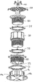
- FIG 1 shows a height adjustable pedestal 10 incorporating slope adjustment, embodying the present invention comprising a number of components which can also be seen in the exploded views 2a and 2b.
- the height adjustable pedestal comprises a base element 12 comprising a circular planar base plate 14 defining a plane on which the pedestal stand in use, and an annular cylindrical portion 16 extending upwards from the base.
- the base is rimless to minimise collection of water.
- a series of holes 17 are defined in the base for bolting, or otherwise fixing, the base to a substrate.
- the cylindrical portion 16 is internally threaded.
- a series of generally triangular buttresses/webs 18 extend from the base plate 14 to the outer face of the cylindrical portion 16.
- Drainage holes 19a are also provided for drainage between the vertical webs to prevent build up of water, particularly when the base is inclined.
- Figure 2b also shows drainage channels 19b which extend from the holes 19a to the rim so that any water which collects on the underside of the base can run out.
- first spacer element 20 is threadably engaged in the base element.
- first spacer element has an annular cross section and a generally open base 22. The upper part of the interior of the spacer element is threaded.
- an external flange 24 is threadably engaged on the external threading of first spacer element 20 and can be rotated to move up and down the threading.
- the locking ring 21 defines a number of protruding lugs 21a which can be grasped to turn the locking ring.
- a locking ring 28 is provided to prevent unintentional rotation of the first spacer element relative to a further cylindrical spacer element 30 which is threadably engaged in the first spacer element 20.
- the locking ring defines projecting lugs 28a which define holes through which wires or the like may be threaded, if desired.
- the locking ring may be rotated to move it up or down the external threading of the spacer element 30. When it is moved down so that it abuts the flange 24 of the spacer element 20, the contact/interference between the two create stability and prevent wobble of the spacer element 30 within the spacer element 20.
- the further spacer element 30 has a generally annular cross section comprising a lower portion 32 which is externally threaded and configured to locate inside the spacer element 20 and an upper, larger diameter portion 34, which is internally threaded.
- the base of the spacer element is substantially open.
- a further locking ring 28 is disposed between a head portion 50 which will be described in more detail below but includes an upper portion 52 and a depending externally threaded cylindrical portion 54 which is threadably engaged inside the threaded portion 34.
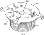
- a slope compensator plate 100 locates on top of the upper portion of the head portion 50 which again will be described in greater detail below.
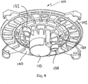
- a cruciform paver separator 150 snap fits into an aperture 108 in the upper portion of the slope adjuster plate.
- the further spacer element 30 is omitted and the head member is threaded directly into the first spacer element 20. Height adjustment is obtained by relative rotation of the head member 50 inside the first spacer element and of the first spacer element 20 inside the base.
- spacer member 30 When greater height is required the spacer member 30 is used as shown in Figure 1 . Two or more spacer elements 30 could be used where yet further height is required.
- a grid of intersecting parallel string lines may be set out on top of a subsurface/sub floor on which a pedestal floor is to be located.
- the spacing between the string lines will correspond to the width of the floor panel members, such as pavers allowing for any slight gaps between the panel members.
- a pedestal is placed at each intersection.
- the height of the pedestals is adjusted to compensate for any slope on the underlying sub floor so that the pedestal floor may be horizontal, if desired.
- the head of the pedestal were perpendicular to the vertical axis of the pedestal, i.e. parallel to the base the pavers will not sit evenly on the pedestals. Accordingly, it is necessary to provide slope compensation as well as height adjustment for the pedestal to account for those circumstances in which the sub-floor is not horizontal but is sloping.
- Figures 3 to 11 illustrate the features of the slope compensating head assembly of an embodiment of the present invention.
- the assembly comprises two components, a slope compensation plate 100 shown in Figures 3 and 4 and a head member 50 shown in Figure 5 .
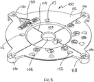
- the head member comprises a head portion 52 from which depends an annular externally threaded cylindrical portion 54. In the centre of the head portion 52 there is a circular aperture 56. Extending around the circular aperture 56 is a first part spherical surface 58 which extends between the perimeter/circumference of the circular aperture 56 and a concentric circle 60. A flange 62 extends from the perimeter of the convex surface to a circular inside perimeter of a further or outer part spherical concave surface 64 in the form of a band which extends in a band/ring around the head member. The flange is recessed slightly relative to the outer edge of the first part spherical surface 58.
- a series of radially aligned strengthening ribs 66 extend across the flange from the perimeter/circumference of the circular aperture 56 to the further part spherical surface 64.
- a series of drainage holes 67 are formed in the flange between adjacent pairs of ribs to prevent build up of water.
- a semi-circular skirt portion 68 (also seen in Figure 9 ) depends from the circumference of the aperture 56.
- a post 70 having a generally triangular cross-section extends up from the head member approximately where the flange and outer part spherical surface meet.
- a series of twelve generally circular holes 72 extend through the first part spherical surface 58.
- the apertures may receive one of two diametrically opposed pegs which depend from the slope adjuster plate described in more detail below.
- the circular holes are superficially similar in appearance, in fact the axes of the circular holes are slightly different and apart from a 0% compensation pair of opposed circular holes are offset relative to the vertical axis of the pedestal, to compensate for the different orientations of the slope adjuster plate on the head member.
- There are two pegs and the apertures are located so that diametrically opposed pairs are aligned at the same angle.
- the centre of the circular holes are not arranged equidistantly from the centre of the head member but are arranged on two part spiral curves each extending through 180°, to account for the differences in position of the slope adjuster plate on the head member.
- the holes corresponding to a particular percentage compensation is further from the centre of the aperture 56, than the holes corresponding to a lesser degree of slope compensation.
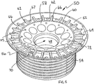
- the slope adjuster plate is best shown in Figures 3 and 4 . It is generally circular in plan view.
- the top surface 102 includes a central circular portion 104 which is recessed relative to an outer ring 106.
- a circular aperture 108 is defined in the centre of the adjustment plate.
- a larger diameter circular skirt portion 110 depends down from the convex underside of the slope adjustment plate encompassing the aperture.
- the centre of the skirt portion is offset from the centre of the aperture in the plate.
- a tab 112 projects radially outwardly from the base of the circular skirt.
- screw holes 113 are provided in the top of the plate through which "tek" screws or the like may pass into receiving/pilot holes 115 in the head 50 (see Figure 5 ). Alternatively the screws may simply be screwed into the head portion 52.
- the top surface of the adjustment plate is marked with a cross 114 passing through the centre of the plate and defined by intersecting relatively shallow grooves.
- a short arm 116 is defined which protrudes beyond the circumference of the top surface of the adjustment plate and defines a hole 118 for tying wire, string or the like to the pedestal.
- the arms can also be used to lift the adjustment plate for adjusting the degree of slope compensation.
- One arm of the cross is marked with an arrow 120 and "UP SLOPE".
- the arrow/arm should point in the upward direction of the slope of the sub floor.
- a series of six spaced apertures 122 are defined in the top surface of the slope adjustment plate.
- the apertures are triangular, and are shaped to receive the triangular post 70 which projects up from the head member 50 and slots into one of the six apertures depending on the relative orientation of the plate 100 and head member 50.
- the degree of slope compensation is from 0% to 5%, in one per cent increments and the apertures are numbered 0 to 5 to indicate the selected degree of slope compensation.
- the post 70 is most preferably in a contrasting colour to the colour of the slope compensation plate.
- the underside of the slope compensation plate defines a convex part spherical surface 130 extending in a band outside the skirt 110.
- the surface is not continuous but is defined by the lower edges of an array of intersecting circular rings and radial ribs. This allows for drainage and for simpler manufacture.
- a flange 140 extends from the outer edge of the convex surface to a further part spherical convex surface 142 defined at the outer edge of the underside of the plate 100.
- the centre of curvature of the further convex surface is the same at that of the convex surface, although its radius of curvature in greater.
- Two diametrically opposed cylindrical pegs 132 and 134 depend down from the convex surface spaced, one peg 134 being relatively wider than the other 132.
- Figures 6 to 11 show the assembled head assembly and illustrate its use.
- the depending skirt 110 of the slope compensator plate 100 passes through the aperture 56 in the centre of the head member.
- the tab 112 and the semicircular skirt 68 ensure that the device can only be assembled in the correct orientation allowing for 180° rotation of the slope compensator relative to the head member, as the tab 112 moves in a semicircular path between the ends of the skirt 68.
- the tab 112 moves in a semicircular path between the ends of the skirt 68.
- the head assembly may be positioned in six different orientations corresponding to the degree of slope compensation from 0% ( Figure 7 ) to 5% ( Figure 8 ), in one per cent increments.
- the degree of slope compensation is determined by which pair of opposed holes 72 the depending pegs 132 and 134 are inserted in. As discussed above, the angle of the central axis of each pair of opposed holes relative to the vertical axis of the pedestal is slightly divergent from the axis to provide the required degree of slope compensation. One peg being wider than the other also helps prevent mis-assembly.
- the triangular apertures 122 indicate which degree of slope compensation is being provided as the protrusion 70 appears in the relevant aperture.
- Figure 7 illustrates 0% slope compensation.
- Figure 8 illustrates 5% slope compensation.
- the UP SLOPE arrow 120 is always pointed in the counter direction of the slope.
- the pedestal as described above is particularly suited to use on sloping sub floors and subsurfaces to create a level pedestal floor, it will be appreciated that it may also be used to create a level raised floor on a level/horizontal sub floor, in which case the slope adjustment plate is set to 0% slope compensation. Alternatively it could also be used to create a sloping pedestal floor on top of a horizontal sub floor/subsurface.
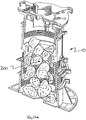
- Figure 12 shows a section through the adjustable pedestal.
- the pedestal is substantially hollow with a substantially free path for material to pass into the pedestal from its open top to the base 14. This is made possible in part by the fact that the interior of the spacer portion is open and at its narrowest in still about 80mm diameter.
- ballast such as gravel, hard core rocks or other suitable materials. This is particularly advantageous where there is a need to increase the weight of the pedestals, for example where they are or may be immersed in water. It also allows for the possibility of filling the pedestal with concrete to increase the strength weight and durability of the pedestal.
- Figure 12a shows the pedestal containing ballast in the form of rocks 200.
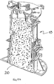
- a concrete 210 filled pedestal 10 is shown in Figure 12b .
Abstract
Description
- This invention relates to a slope compensator for a pedestal for elevated floors.
- It is known to provide elevated or raised floors, also known as pedestal floors. Elevated flooring incorporates a number of height adjustable pedestals which are uniformly distributed over a subsurface/sub floor such as a concrete floor of a multi-story building, a roof, terrace, or any other surface on top of which it is desired to locate an elevated floor. Other non-exhaustive applications of pedestal floors include technical floors for laboratories, fitting out old buildings, patios, balconies, swimming pool surrounds and decking. The pedestals cooperate in supporting floor panels, such as pavers, or other floor surfaces. The panel members provide a relatively flat high strength floor.
- Problems arise when forming a raised surface on a sub floor/subsurface which is not itself horizontal such as roof terrace which will typically slope at an angle of up to 5% in order to allow water run off.
- Although height adjustable pedestals with means for compensating for slope, are known to address the problem of slope, existing pedestals incorporating slope adjustment tend to be rather awkward to use and adjust. One common problem with existing systems is that where slope compensation is provided, it may not always be immediately apparent which direction the head of the pedestal should face, relative to the slope of the subsurface.
- One further problem with existing pedestal jacks is stability of the pedestals and this is a problem which is currently and somewhat unsatisfactorily addressed by tying wire to the pedestals which is awkward messy and does not work well.
-
DE 37 09 017 discloses a support for raised floors with adjustable height comprising an internally threaded base element, and intermediate extension element and a top element having a concave top on which rests a convex swinging cap with diaphragms on which the flat elements of the floor can rest. -
EP 0309 399 discloses a slope adjustable head on a pedestal defining a head with a convex surface and a plate having a concave surface which includes a screw for fixing the plate relative to the concave surface. -
EP 1 304 426 andUS 3,318,057 both disclose pedestals including interfacing convex and concave surfaces, although neither discloses fixing means for fixing the surfaces. - Any discussion of documents, acts, materials, devices, articles or the like which has been included in the present specification is solely for the purpose of providing a context for the present invention. It is not to be taken as an admission that any or all of these matters form part of the prior art base or were common general knowledge in the field relevant to the present invention as it existed before the priority date of each claim of this application.
- According to one aspect of the present invention, there is provided a slope adjustable head for an adjustable pedestal adapted to support panel members of an elevated floor structure, the head comprising:
- a head member; and
- a slope adjustment plate,
- wherein the head member defines a first part-spherical surface having a first radius of curvature, and the slope adjustment plate has a first face defining a planar area and an opposite face defining a second part-spherical surface having substantially the same radius of curvature as the first part-spherical surface, and wherein the second part spherical surface may be supported on the first part spherical surface, with relative movement of the second part-spherical surface on the first part spherical surface adjusting the angle of the planar portion of the adjustment plate relative to the plane of the base, characterised in that the slope adjustment plate defines at least one depending peg and the head member defines an array of holes which extend about the centre of the top surface of the head member and which are adapted to receive said peg for fixing the slope adjustment plate relative to the head member in two or more different relative orientations.
- The use of two part-spherical surfaces to provide slope compensation, allows for a relatively straightforward adjustment of the slope of the adjustment plate by rotation of the adjustment plate about the centre of curvature of its part-spherical surface.
In a preferred embodiment, the holes are not equidistant from the centre of the head member but rather are located on a gentle spiral curve to account for relative movement of the adjustment plate on the head member. - Most preferably, a relatively large circular aperture is defined in the centre of the head member and a semi-circular skirt portion depends from the circumference of the aperture. A relatively smaller circular aperture may also be defined in the centre of the adjustment plate. A larger diameter circular skirt portion may depend down from the convex (underside) of the slope adjustment plate encompassing the aperture and whose centre is offset from the centre of the aperture in the plate. A projecting tab may extend outwardly from the base of the circular skirt.
- The apertures in the adjustment plate allows an installer of a pedestal floor to adjust the relative orientation of plate and head member by inserting their finger or thumb in the aperture, raising, rotating and lowering the plate. The projecting tab and semi-circular skirt assist in preventing mis-assembly and maladjustment of the head assembly.
- In order to provide a pedestal having sufficient strength and load bearing area, it is preferred that both the head member and the slope adjustment plate define further part spherical surfaces which bear against each other in use to distribute loads. In particular the edge area of the head member may define a further part spherical surface which extends in a ring around the perimeter of the head member. The further part-spherical surface may be concentric with the centre of curvature of the first concave part-spherical surface but may have a larger radius of curvature. Similarly the edge area of the slope adjustment plate may define a part spherical convex surface which extends in a ring around the perimeter of the plate, which is concentric with the centre of curvature of the second convex part-spherical surface but may have a larger radius of curvature. This arrangement provides a second load bearing at the outer edges of the plate and head member, in addition to the first and second concave and convex surfaces which share any load carried by the pedestal.
- An annular flange and a series of radially extending support ribs may extend between the first concave surface of the head member and the concave outer ring and a series of through holes may be defined in the flange to prevent the build up of water in the head member.
- The adjustment plate is typically generally circular in plan view. Preferably, the top of the adjustment plate is marked with a cross passing through the centre of the plate, typically in the form of a relatively shallow groove. At each end of the cross a short arm may be defined which protrudes beyond the circumference of the top surface of the adjustment plate. The arm may define a hole for tying wire, string or the like to the pedestal.
- One line/arm of the cross is preferably clearly marked with an arrow and "UP SLOPE" or the like to indicate that, in use, the arrow/arm should point in the upward direction of the slope of the sub floor.
- In a preferred embodiment, a series of apertures typically six, are defined in the slope adjustment plate. The apertures may have particular shape, e.g. triangular, and a correspondingly shaped protrusion may project up from the head member and slot through into one of the six apertures. The degree of slope compensation (typically 0% to 5%, in one per cent increments) provided by the head assembly may be indicated by which aperture the protrusion is located in. The protrusion is most preferably in a contrasting colour to the colour of the slope compensation plate. The numbers zero to five are typically defined on the adjustment plate adjacent the aperture providing that percentage of slope compensation.
- To provide a combination of light weight and sufficient strength, the pedestal is typically injection moulded in a plastics material such as polypropylene, however other suitable materials or manufacturing methods could be used.
- In another aspect of the invention there is provided an adjustable pedestal as claimed in claim 15.
- In another aspect of the invention there is provided an adjustable pedestal as claimed in
claim 16. - The locking elements have the advantage of considerably increasing the stability of the pedestal.
- In another aspect of the invention there is provided an adjustable pedestal as claimed in
claim 17. - The adjustable pedestal may be filled with ballast at least some of which has a diameter of 8mm or more, or 1cm or more, or 2cm or more or larger up to the narrowest part of the internal diameter of the spacer portion which is about 80mm.
- The adjustable pedestal may be filled with concrete to create a concrete pillar enclosed by the pedestal for improved strength and durability.
- Throughout this specification the word "comprise", or variations such as "comprises" or "comprising", will be understood to imply the inclusion of a stated element, integer or step, or group of elements, integers or steps, but not the exclusion of any other element, integer or step, or group of elements, integers or steps.
- A specific embodiment of the present invention will now be described, by way of example only, and with reference to the accompanying drawings in which:
-
Figure 1 shows a view of a height adjustable pedestal embodying the present invention; -
Figure 2a is an exploded view seen from one side and above of the height adjustable pedestal ofFigure 1 ; - Figure 2b is an exploded view seen from one side and below of the height adjustable pedestal shown in
Figure 1 ; -
Figure 3 is a isometric view of the top of a slope adjustment plate of the height adjustable pedestal; -
Figure 4 is an isometric view of the underside of slope adjustment plate ofFigure 3 ; -
Figure 5 is a isometric view of the top of a head member of the pedestal shown inFigure 1 ; -
Figure 6 is an isometric view seen from above of an assembly of the slope compensator plate ofFigure 3 and the head member ofFigure 5 ; -
Figure 7 is a side view of the assembly ofFigure 6 showing 0% compensation; -
Figure 8 is a side view of the assembly ofFigure 6 showing 5% slope compensation; -
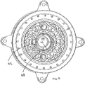
Figure 9 is an underneath plan view of the assembly shown inFigures 6 to 8 ; -
Figure 10 is a cross section through the assembly also showing a paver spacer; -
Figure 11 is an exploded isometric sectional view of the slope adjustment plate and head member ofFigure 10 ; -
Figure 12 is a section through a pedestal embodying the invention; -
Figure 12a shows the sectioned pedestal containing ballast; and -
Figure 12b shows the sectioned pedestal containing concrete. - Referring to the drawings,
Figure 1 shows a heightadjustable pedestal 10 incorporating slope adjustment, embodying the present invention comprising a number of components which can also be seen in the exploded views 2a and 2b. The height adjustable pedestal comprises abase element 12 comprising a circularplanar base plate 14 defining a plane on which the pedestal stand in use, and an annularcylindrical portion 16 extending upwards from the base. The base is rimless to minimise collection of water. A series ofholes 17 are defined in the base for bolting, or otherwise fixing, the base to a substrate. Thecylindrical portion 16 is internally threaded. A series of generally triangular buttresses/webs 18 extend from thebase plate 14 to the outer face of thecylindrical portion 16.Drainage holes 19a are also provided for drainage between the vertical webs to prevent build up of water, particularly when the base is inclined. Figure 2b also shows drainage channels 19b which extend from theholes 19a to the rim so that any water which collects on the underside of the base can run out. - As shown in
Figure 1 an externally threaded cylindricalfirst spacer element 20 is threadably engaged in the base element. As is best seen inFigures 2a and 2b, the first spacer element has an annular cross section and a generallyopen base 22. The upper part of the interior of the spacer element is threaded. At the top of the spacer element there is anexternal flange 24 from which extend a series of projecting lugs 26 which define apertures to enable wire to be threaded therethrough. Anannular locking ring 21 is threadably engaged on the external threading offirst spacer element 20 and can be rotated to move up and down the threading. The lockingring 21 defines a number ofprotruding lugs 21a which can be grasped to turn the locking ring. When the locking is moved down so that it abuts the top of thebase element 12, the contact/interference between the two create stability and prevent wobble of thefirst spacer element 20 within thebase element 12. - A locking
ring 28 is provided to prevent unintentional rotation of the first spacer element relative to a furthercylindrical spacer element 30 which is threadably engaged in thefirst spacer element 20. The locking ring defines projectinglugs 28a which define holes through which wires or the like may be threaded, if desired. The locking ring may be rotated to move it up or down the external threading of thespacer element 30. When it is moved down so that it abuts theflange 24 of thespacer element 20, the contact/interference between the two create stability and prevent wobble of thespacer element 30 within thespacer element 20. - The
further spacer element 30 has a generally annular cross section comprising alower portion 32 which is externally threaded and configured to locate inside thespacer element 20 and an upper, larger diameter portion 34, which is internally threaded. The base of the spacer element is substantially open. - A further locking
ring 28 is disposed between ahead portion 50 which will be described in more detail below but includes anupper portion 52 and a depending externally threadedcylindrical portion 54 which is threadably engaged inside the threaded portion 34. Aslope compensator plate 100 locates on top of the upper portion of thehead portion 50 which again will be described in greater detail below. Acruciform paver separator 150 snap fits into an aperture 108 in the upper portion of the slope adjuster plate. - The pieces together form a telescopic height adjustable jack which can range in height from a minimum of around 60 mm up to approximately 1050 mm. For a pedestal having the lowest possible height the
further spacer element 30 is omitted and the head member is threaded directly into thefirst spacer element 20. Height adjustment is obtained by relative rotation of thehead member 50 inside the first spacer element and of thefirst spacer element 20 inside the base. - When greater height is required the
spacer member 30 is used as shown inFigure 1 . Two or morespacer elements 30 could be used where yet further height is required. - In use, a grid of intersecting parallel string lines may be set out on top of a subsurface/sub floor on which a pedestal floor is to be located. The spacing between the string lines will correspond to the width of the floor panel members, such as pavers allowing for any slight gaps between the panel members. A pedestal is placed at each intersection. The height of the pedestals is adjusted to compensate for any slope on the underlying sub floor so that the pedestal floor may be horizontal, if desired. However, it will be appreciated that if the head of the pedestal were perpendicular to the vertical axis of the pedestal, i.e. parallel to the base the pavers will not sit evenly on the pedestals. Accordingly, it is necessary to provide slope compensation as well as height adjustment for the pedestal to account for those circumstances in which the sub-floor is not horizontal but is sloping.
-
Figures 3 to 11 illustrate the features of the slope compensating head assembly of an embodiment of the present invention. As discussed above, the assembly comprises two components, aslope compensation plate 100 shown inFigures 3 and4 and ahead member 50 shown inFigure 5 . - The head member, best seen in
Figure 5 , comprises ahead portion 52 from which depends an annular externally threadedcylindrical portion 54. In the centre of thehead portion 52 there is a circular aperture 56. Extending around the circular aperture 56 is a first partspherical surface 58 which extends between the perimeter/circumference of the circular aperture 56 and aconcentric circle 60. Aflange 62 extends from the perimeter of the convex surface to a circular inside perimeter of a further or outer part sphericalconcave surface 64 in the form of a band which extends in a band/ring around the head member. The flange is recessed slightly relative to the outer edge of the first partspherical surface 58. A series of radially aligned strengtheningribs 66 extend across the flange from the perimeter/circumference of the circular aperture 56 to the further partspherical surface 64. A series of drainage holes 67 are formed in the flange between adjacent pairs of ribs to prevent build up of water. - A semi-circular skirt portion 68 (also seen in
Figure 9 ) depends from the circumference of the aperture 56. - A
post 70 having a generally triangular cross-section extends up from the head member approximately where the flange and outer part spherical surface meet. - A series of twelve generally circular holes 72 extend through the first part
spherical surface 58. In use the apertures may receive one of two diametrically opposed pegs which depend from the slope adjuster plate described in more detail below. Although the circular holes are superficially similar in appearance, in fact the axes of the circular holes are slightly different and apart from a 0% compensation pair of opposed circular holes are offset relative to the vertical axis of the pedestal, to compensate for the different orientations of the slope adjuster plate on the head member. There are two pegs and the apertures are located so that diametrically opposed pairs are aligned at the same angle. Also the centre of the circular holes are not arranged equidistantly from the centre of the head member but are arranged on two part spiral curves each extending through 180°, to account for the differences in position of the slope adjuster plate on the head member. The holes corresponding to a particular percentage compensation is further from the centre of the aperture 56, than the holes corresponding to a lesser degree of slope compensation. - The slope adjuster plate is best shown in
Figures 3 and4 . It is generally circular in plan view. Thetop surface 102 includes a centralcircular portion 104 which is recessed relative to an outer ring 106. A circular aperture 108 is defined in the centre of the adjustment plate. As is best seen inFigure 4 , a larger diametercircular skirt portion 110 depends down from the convex underside of the slope adjustment plate encompassing the aperture. As is best seen inFigure 9 , the centre of the skirt portion is offset from the centre of the aperture in the plate. Atab 112 projects radially outwardly from the base of the circular skirt. - In order to fix the slope compensation plate relative to the
head 50 and prevent accidental dislodgement of the same due to wind, an impact or the like, screwholes 113 are provided in the top of the plate through which "tek" screws or the like may pass into receiving/pilot holes 115 in the head 50 (seeFigure 5 ). Alternatively the screws may simply be screwed into thehead portion 52. - The top surface of the adjustment plate is marked with a
cross 114 passing through the centre of the plate and defined by intersecting relatively shallow grooves. At each end of the cross ashort arm 116 is defined which protrudes beyond the circumference of the top surface of the adjustment plate and defines ahole 118 for tying wire, string or the like to the pedestal. The arms can also be used to lift the adjustment plate for adjusting the degree of slope compensation. - One arm of the cross is marked with an
arrow 120 and "UP SLOPE". In use, the arrow/arm should point in the upward direction of the slope of the sub floor. - A series of six spaced
apertures 122 are defined in the top surface of the slope adjustment plate. The apertures are triangular, and are shaped to receive thetriangular post 70 which projects up from thehead member 50 and slots into one of the six apertures depending on the relative orientation of theplate 100 andhead member 50. In the described embodiment the degree of slope compensation is from 0% to 5%, in one per cent increments and the apertures are numbered 0 to 5 to indicate the selected degree of slope compensation. Thepost 70 is most preferably in a contrasting colour to the colour of the slope compensation plate. - The underside of the slope compensation plate defines a convex part
spherical surface 130 extending in a band outside theskirt 110. The surface is not continuous but is defined by the lower edges of an array of intersecting circular rings and radial ribs. This allows for drainage and for simpler manufacture. Aflange 140 extends from the outer edge of the convex surface to a further part sphericalconvex surface 142 defined at the outer edge of the underside of theplate 100. The centre of curvature of the further convex surface is the same at that of the convex surface, although its radius of curvature in greater. - Two diametrically opposed
cylindrical pegs peg 134 being relatively wider than the other 132. -
Figures 6 to 11 show the assembled head assembly and illustrate its use. With reference toFigures 10 and11 in particular, the dependingskirt 110 of theslope compensator plate 100, passes through the aperture 56 in the centre of the head member. Thetab 112 and thesemicircular skirt 68 ensure that the device can only be assembled in the correct orientation allowing for 180° rotation of the slope compensator relative to the head member, as thetab 112 moves in a semicircular path between the ends of theskirt 68. When the tab reaches the skirt, further rotation is prevented by thetab 112 abutting theskirt 68. This is best seen inFigure 9 . - In the described embodiment the head assembly may be positioned in six different orientations corresponding to the degree of slope compensation from 0% (
Figure 7 ) to 5% (Figure 8 ), in one per cent increments. The degree of slope compensation is determined by which pair of opposed holes 72 the dependingpegs triangular apertures 122 indicate which degree of slope compensation is being provided as theprotrusion 70 appears in the relevant aperture.Figure 7 illustrates 0% slope compensation.Figure 8 illustrates 5% slope compensation. To adjust the degree of slope compensation an operator inserts their finger or thumb in the aperture 108 in the plate, or lifts theshort arms 116, with the tab preventing accidental removal, and simply rotates the plate until the protrusion is located below therelevant aperture 122 indicating the desired degree of slope compensation, and lowers the plate at which time thepegs UP SLOPE arrow 120 is always pointed in the counter direction of the slope. - Numerous variations to the described embodiment are possible. For example although 0 to 5% slope compensation is provided in the described example, it will be appreciated that it would be possible to create
say 0 to 6% compensation, in whichcase 14 holes will be provided in the central concave area of the head member, or greater degrees of compensation such as 0 to 10% or more. - Although the pedestal as described above is particularly suited to use on sloping sub floors and subsurfaces to create a level pedestal floor, it will be appreciated that it may also be used to create a level raised floor on a level/horizontal sub floor, in which case the slope adjustment plate is set to 0% slope compensation. Alternatively it could also be used to create a sloping pedestal floor on top of a horizontal sub floor/subsurface.
-
Figure 12 shows a section through the adjustable pedestal. With reference to that figure, it can be seen that if theslope compensator plate 100 and optionally also thehead portion 50 are removed the pedestal is substantially hollow with a substantially free path for material to pass into the pedestal from its open top to thebase 14. This is made possible in part by the fact that the interior of the spacer portion is open and at its narrowest in still about 80mm diameter. This allows the filling of the pedestal with ballast such as gravel, hard core rocks or other suitable materials. This is particularly advantageous where there is a need to increase the weight of the pedestals, for example where they are or may be immersed in water. It also allows for the possibility of filling the pedestal with concrete to increase the strength weight and durability of the pedestal.Figure 12a shows the pedestal containing ballast in the form ofrocks 200. A concrete 210 filledpedestal 10 is shown inFigure 12b . - It will be appreciated by persons skilled in the art that numerous variations and/or modifications may be made to the specific embodiments without departing from the scope of the invention as broadly defined by the appended claims. The present embodiments are, therefore, to be considered in all respects as illustrative and not restrictive.
Claims (17)
- A slope adjustable head for an adjustable pedestal adapted to support panel members of an elevated floor structure, the head comprising:a head member (50) ; anda slope adjustment plate (100) ,wherein the head member (50) defines a first part-spherical surface (58) having a first radius of curvature, and the slope adjustment plate has a first face (102) defining a planar area and an opposite face defining a second part-spherical surface (130) having substantially the same radius of curvature as the first part-spherical surface, and wherein the second part spherical surface (130) may be supported on the first part spherical surface (58), with relative movement of the second part-spherical surface on the first part spherical surface adjusting the angle of the planar portion of the adjustment plate relative to the plane of the base,characterised in that the slope adjustment plate (100) defines at least one depending peg (132,134) and the head member defines an array of holes (72) which extend about the centre of the top surface of the head member and which are adapted to receive the peg for fixing the slope adjustment plate relative to the head member in two or more different relative orientations.
- A slope adjustable head as claimed in claim 1 wherein the first part-spherical surface is concave and the second part spherical surface is convex.
- A slope adjustable head as claimed in claim 1 or claim 2 wherein adjustment of the slope of the slope adjustment plate (100) is by rotation of the slope adjustment plate about the centre of curvature of the second part spherical surface.
- A slope adjustable head as claimed in any one of claims 1 to 3 wherein the array of holes (72) are located on a spiral curve.
- A slope adjustable head as claimed in any one of claims 1 to 4 wherein a circular aperture (56) is defined in the centre of the head member and a semi-circular skirt portion (68) depends from the circumference of that aperture.
- A slope adjustable head as claimed in claim 5 wherein a circular aperture (108) which is relatively smaller than the circular aperture in the centre of the head member is also defined in the centre of the adjustment plate and wherein a circular skirt portion (110) depends down from the underside of the slope adjustment plate encompassing the aperture and wherein the centre of the skirt portion is offset from the centre of the aperture in the plate.
- A slope adjustable head as claimed in claim 6 wherein a projecting tab (112) extends outwardly from the base of the circular skirt portion of the plate (100).
- A slope adjustable head as claimed in any one of claims 1 to 7 wherein a further part spherical surface (64) extends in a ring around the perimeter of the head member which is concentric with the centre of curvature of the first part-spherical surface but has a larger radius of curvature and defines a concave outer ring.
- A slope adjustable head as claimed in claim 8 wherein the slope adjustment plate defines a yet further part spherical surface (142) which extends in a ring around the perimeter of the plate, which is concentric with the centre of curvature of the second part-spherical surface but has a larger radius of curvature.
- A slope adjustable head as claimed in claim 8 or 9 wherein an annular flange (62) and a series of radially extending support ribs (66) extend between the first part spherical surface (58) of the head member and the concave outer ring (64) and a series of through holes (67) are defined in the flange to prevent the build up of water in the head member.
- A slope adjustable head as claimed in any one of claims 1 to 10 wherein the adjustment plate is generally circular in plan.
- A slope adjustable head as claimed in claim 11 wherein the top of the adjustment plate is marked with a cross (114) passing through the centre of the plate, and at each end of the cross an arm (116) is defined which protrudes beyond the circumference of the top surface of the adjustment plate and which defines a hole (118) for tying wire, string or the like to the pedestal.
- A slope adjustable head as claimed in claim 12 wherein one arm of the cross is marked with an arrow which indicates in use, the correct direction of the slope of the floor on which the pedestal sits.
- A slope adjustable head as claimed in any one of claims 1 to 13 wherein a series of apertures (112) having a particular shape are defined in the slope adjustment plate and a correspondingly shaped protrusion (70) projects up from the head member and slots through into one of the apertures and wherein the degree of slope compensation provided by the head assembly is indicated by which aperture the protrusion is located in.
- An adjustable pedestal (10) adapted to support panel members of an elevated floor structure including a slope adjustable head as claimed in any one of claims 1 to 14, the pedestal further comprising:a height adjustable support structure including a base (12) and a head assembly (50,100), the base (12) defining a plane on which the support structure stands in use, said head assembly including: the slope adjustable head as claimed in any one of claims 1 to 14.
- An adjustable pedestal (10) adapted to support panel members of an elevated floor structure including a slope adjustable head as claimed in any one of claims 1 to 14 , the pedestal further comprising:a height adjustable support structure including a base (12) and a head assembly (50,100), the base (12) defining a plane on which the support structure stands in use, and at least one spacer element (20, 30) located between the base and the head assembly (50, 100), and wherein the base defines an open top and is internally threaded to receive a lower part of the spacer element (20, 30), which is externally threaded to engage with the internally threaded portion of the base such that relative rotation of the two adjust the height of the pedestal anda locking ring (28) which is located on the externally threaded portion of the spacer element which may be rotated to move it into contact with the top of the base or another spacer element if more than one are present, to reduce or prevent relative movement of the base and spacer elements.
- An adjustable pedestal adapted to support panel members of an elevated floor structure including a slope adjustable head as claimed in any one of claims 1 to 14 , the pedestal further comprising:a height adjustable support structure including a base (12) and a head assembly (50,100) incorporating the slope adjustable head, the base (12) defining a plane on which the support structure stands in use, and at least one spacer element (20, 30), located between the base and the head assembly (50, 100), and wherein the base (12) defines an open top and is internally threaded to receive a lower part of the spacer element (20, 30)" which is externally threaded to engage with the internally threaded portion of the base such that relative rotation of the two adjust the height of the pedestal, the base and interior of the spacer element (20, 30), being substantially open thereby allowing relatively large materials of a diameter of around 8mm, typically 10mm or 20mm or more to pass unhindered from the top of the spacer element (20, 30), to its bottom and thereby allowing such materials to pass down the pedestal with the head assembly removed, to the base of the pedestal.
Applications Claiming Priority (2)
| Application Number | Priority Date | Filing Date | Title |
|---|---|---|---|
| AU2005905990A AU2005905990A0 (en) | 2005-10-28 | Slope compensator for pedestal for elevated floors | |
| PCT/AU2006/001613 WO2007048204A1 (en) | 2005-10-28 | 2006-10-27 | Slope compensator for pedestal for elevated floors |
Publications (3)
| Publication Number | Publication Date |
|---|---|
| EP1948885A1 EP1948885A1 (en) | 2008-07-30 |
| EP1948885A4 EP1948885A4 (en) | 2010-03-24 |
| EP1948885B1 true EP1948885B1 (en) | 2012-04-18 |
Family
ID=37967356
Family Applications (1)
| Application Number | Title | Priority Date | Filing Date |
|---|---|---|---|
| EP06790440A Not-in-force EP1948885B1 (en) | 2005-10-28 | 2006-10-27 | Slope compensator for pedestal for elevated floors |
Country Status (7)
| Country | Link |
|---|---|
| US (1) | US7866096B2 (en) |
| EP (1) | EP1948885B1 (en) |
| JP (1) | JP5147705B2 (en) |
| KR (1) | KR101319511B1 (en) |
| AT (1) | ATE554245T1 (en) |
| ES (1) | ES2386260T3 (en) |
| WO (1) | WO2007048204A1 (en) |
Cited By (1)
| Publication number | Priority date | Publication date | Assignee | Title |
|---|---|---|---|---|
| EP2115240B1 (en) | 2007-02-16 | 2017-10-11 | Lee, Alan Sian Ghee | Improved batten/joist support |
Families Citing this family (96)
| Publication number | Priority date | Publication date | Assignee | Title |
|---|---|---|---|---|
| US5205290A (en) | 1991-04-05 | 1993-04-27 | Unger Evan C | Low density microspheres and their use as contrast agents for computed tomography |
| CA2422750C (en) * | 2003-03-12 | 2012-05-01 | Simon Walker | Rail and railing system |
| CA2460983C (en) * | 2004-03-26 | 2012-05-15 | Simon Walker | Picket for a railing system |
| CA2462360C (en) * | 2004-04-01 | 2010-08-03 | Simon Walker | Post system for a railing |
| US9004439B2 (en) * | 2006-04-04 | 2015-04-14 | Peak Innovations Inc. | Post anchor |
| US8056288B2 (en) * | 2006-04-28 | 2011-11-15 | Albini & Fontanot S.P.A. | Step for modular staircases and relative staircase |
| US20080105172A1 (en) * | 2006-11-02 | 2008-05-08 | John Repasky | Pedestal for Ballast Block Decking |
| US8381461B2 (en) * | 2006-11-02 | 2013-02-26 | John Repasky | Stabilizing systems for deck pedestals |
| US20090188178A1 (en) * | 2008-01-28 | 2009-07-30 | Latham International | Adjustable Footing Assembly For Pool Steps |
| US20100005739A1 (en) * | 2008-07-14 | 2010-01-14 | Frank Pendergast Incorporated | Non-magentic access floor system for use in electronic imaging rooms |
| US7921612B2 (en) * | 2008-08-31 | 2011-04-12 | United Construction Products, Inc. | Method and device for supporting a structure |
| ITPG20090001A1 (en) * | 2009-01-12 | 2010-07-13 | Stefano Lenoci | BASE - OUTDOOR FLOOR SUPPORT FOR DOGHE |
| DE202009001392U1 (en) * | 2009-02-05 | 2010-06-24 | Gutjahr, Walter | Support device for a deployable floor covering |
| US9404264B2 (en) | 2009-03-09 | 2016-08-02 | J. Van Walraven Holding B.V. | Roof support system |
| ITMI20090938A1 (en) * | 2009-05-27 | 2010-11-28 | Massimo Veggian | SUPPORT FOR VARIABLE INCLINATION FOR RAISED OR FLOATING FLOORS. |
| US20120291369A1 (en) * | 2009-07-17 | 2012-11-22 | United Construction Products, Inc. | Support pedestal assembly including a stabilizing collar for stabilizing a support structure |
| US8429860B2 (en) * | 2009-07-17 | 2013-04-30 | United Construction Products, Inc. | Stability bracing of a support structure for elevating a building surface |
| US8181399B2 (en) * | 2009-07-17 | 2012-05-22 | United Construction Products, Inc. | Stability bracing of a support structure for elevating a building structure |
| JP2011052430A (en) * | 2009-09-01 | 2011-03-17 | Sanyo Industries Ltd | Floor supporting device |
| US9677690B2 (en) * | 2010-02-08 | 2017-06-13 | Thomas & Betts International, Llc | Multi-purpose roof-top support |
| US8717317B2 (en) * | 2010-02-22 | 2014-05-06 | Canon Kabushiki Kaisha | Display control device and method for controlling display on touch panel, and storage medium |
| IT1398177B1 (en) * | 2010-02-25 | 2013-02-14 | Eterno Ivica Srl | SUPPORT FOR RAISED FLOORS |
| US8453391B2 (en) * | 2010-03-26 | 2013-06-04 | Ramin Tabibnia | Apparatus for establishing a paver over a subsurface |
| US9879385B2 (en) | 2010-03-26 | 2018-01-30 | Ramin Tabibnia | Apparatus and related methods of paving a subsurface |
| US9284693B2 (en) * | 2010-03-26 | 2016-03-15 | Ramin Tabibnia | Apparatus and related methods of paving a subsurface |
| US8850753B2 (en) * | 2010-03-26 | 2014-10-07 | Ramin Tabibnia | Apparatus for establishing a paver surface over a subsurface |
| FR2958114B1 (en) * | 2010-03-31 | 2013-04-26 | Fournier | SUPPORT ELEMENT FOR A FLOOR OF A PORCHERIE BASED ON BEAMS |
| AU2011202121B2 (en) * | 2010-05-12 | 2012-08-23 | Alan Sian Ghee Lee | Adjustable pedestal |
| GB201013937D0 (en) * | 2010-08-20 | 2010-10-06 | Ellis Gordon & Co | Height adjustment apparatus |
| US8671635B2 (en) * | 2011-01-04 | 2014-03-18 | Nigel Jones | Perimeter pedestals |
| KR101243873B1 (en) * | 2011-07-14 | 2013-03-20 | 주식회사 수주엔지니어링 | Structural pedestal supporting many types of finishing materials |
| KR101243872B1 (en) * | 2011-07-14 | 2013-03-20 | 주식회사 수주엔지니어링 | Structural pedestal preventing distortion |
| KR101133198B1 (en) * | 2011-07-14 | 2012-05-03 | 주식회사 수주엔지니어링 | Structural pedestal improved adjusting slope |
| US8690109B2 (en) | 2011-08-03 | 2014-04-08 | Haworth, Inc. | Automatic gap adjustor |
| EP2610416A1 (en) | 2011-12-27 | 2013-07-03 | Solidor Rubber & Products | Support stand for supporting an item at a distance from an underlying surface |
| US8955276B2 (en) * | 2012-01-25 | 2015-02-17 | Steven James Wall | Raised flooring apparatus and system |
| AU342985S (en) * | 2012-05-10 | 2012-06-18 | Elmich Pte Ltd | Spacer for pavers |
| US8733031B2 (en) * | 2012-05-29 | 2014-05-27 | United Construction Products, Inc. | Attachment member and support structure for supporting a structural building component |
| AU2013207651B2 (en) * | 2012-08-01 | 2018-01-18 | Tabibnia Ramin | Improved Apparatus for Establishing a Paver Surface Over a Substrate |
| CN104029797B (en) * | 2013-03-05 | 2016-07-06 | 中集海洋工程研究院有限公司 | The deck of a kind of drilling platforms is hung pedestal and is added strong method |
| US9803377B2 (en) * | 2013-03-13 | 2017-10-31 | The Ipe Clip Fastener Company, Llc | Height and slope adjustable pedestal |
| CA2902929C (en) * | 2013-03-13 | 2021-03-30 | The Ipe Clip Fastener Company, Llc | Pedestal elevation system |
| USD728185S1 (en) * | 2013-03-15 | 2015-04-28 | The Ipe Clip Fastener Co., Llc | Tiltable lockable elevating pedestal |
| TWI513993B (en) | 2013-03-26 | 2015-12-21 | Ind Tech Res Inst | 3-axis magnetic field sensor, fabrication method of magnetic sensing structure and magnetic field sensing circuit |
| US8769893B1 (en) * | 2013-04-12 | 2014-07-08 | Kwikspace Guam | Twist lock portable building footing |
| US9637257B2 (en) * | 2013-05-24 | 2017-05-02 | L'Air Liquide Société Anonyme Pour L'Étude Et L'Exploitation Des Procedes Georges Claude | Weather shelter for use in a remote manufacturing yard |
| US10815678B2 (en) * | 2013-06-14 | 2020-10-27 | Phillip Busby | Flooring support system |
| US10815673B2 (en) * | 2013-06-14 | 2020-10-27 | Phillip Busby | Flooring support system |
| US10829941B2 (en) * | 2013-06-14 | 2020-11-10 | Phillip Busby | Flooring support system |
| US11002023B2 (en) * | 2013-06-14 | 2021-05-11 | Phillip Busby | Flooring support system |
| US10947739B2 (en) * | 2013-06-14 | 2021-03-16 | Phillip Busby | Flooring support system |
| FR3007052B1 (en) * | 2013-06-18 | 2015-10-16 | Wilfried Andres | PLOT TYPE SUPPORT DEVICE FOR THE CONSTRUCTION OF TERRACES. |
| US8898999B1 (en) | 2013-11-27 | 2014-12-02 | United Construction Products, Inc. | Restraint system for elevated surface tiles |
| EP2933396B1 (en) | 2014-04-15 | 2019-09-18 | Ramin Tabibnia | Elevated paver support system |
| ITMI20140159U1 (en) * | 2014-05-02 | 2015-11-02 | Terry Store Age S P A | MODULAR SHELVING WITH HIGH FLEXIBILITY OF USE |
| US9487965B2 (en) | 2015-04-03 | 2016-11-08 | Dee Volin | Automatic-water-shedding height-adjustable three-dimensionally-adjustable post-base system |
| US10106991B2 (en) | 2015-06-01 | 2018-10-23 | Wausau Tile, Inc. | Paver pedestal and method of installing same |
| BE1023695B1 (en) * | 2015-12-14 | 2017-06-16 | Buzon Pedestal International S.A. | DEVICE FOR COMPENSATING THE INCLINATION OF A BUILDING SURFACE |
| AU367851S (en) * | 2016-02-05 | 2016-03-23 | Elmich Pte Ltd | Pedestal adaptor |
| CN106049768B (en) * | 2016-05-31 | 2019-05-31 | 江苏南通三建集团股份有限公司 | A kind of overhead heat insulation supporting member and its construction method keeping the temperature pitched roof |
| DE102016110212B4 (en) * | 2016-06-02 | 2018-02-22 | Achim Stiehler Gmbh & Co. Kg | Support device for the construction of elevated accessible surfaces, for example, terraces or other floors |
| IT201600131200A1 (en) * | 2016-12-27 | 2018-06-27 | Andrea Marana | IMPROVED SUPPORT SYSTEM FOR RAISED FLOORS. |
| KR101826467B1 (en) * | 2017-03-13 | 2018-02-08 | 박호관 | Block post |
| US10480611B2 (en) * | 2017-03-28 | 2019-11-19 | SK Commercial Construction, Inc. | Method for improved semiconductor processing equipment tool pedestal / pad vibration isolation and reduction |
| US10060501B1 (en) * | 2017-03-28 | 2018-08-28 | SK Commercial Construction, Inc. | Method for improved semiconductor processing equipment tool pedestal/pad vibration isolation and reduction |
| US9995365B1 (en) * | 2017-03-28 | 2018-06-12 | SK Commercial Construction, Inc. | Method and system for improved semiconductor processing equipment vibration isolation and reduction |
| US10113610B2 (en) * | 2017-03-28 | 2018-10-30 | SK Commercial Construction, Inc. | Method for improved semiconductor processing equipment tool pedestal / pad vibration isolation and reduction |
| US10827830B2 (en) | 2017-05-23 | 2020-11-10 | Siso A/S | Method of adjusting the inclination of a furniture leg and a mounting set |
| JP2019011638A (en) * | 2017-06-30 | 2019-01-24 | 株式会社トムス | Floor bundle |
| CN109496255A (en) * | 2017-07-02 | 2019-03-19 | Sk商业建筑公司 | Improved semiconductor processing equipment tool base/liner vibration isolation and vibration damping method |
| JP2019082086A (en) * | 2017-10-31 | 2019-05-30 | フクビ化学工業株式会社 | Prefabricated room support leg, curable material filling prefabricated room support leg, and method of adjusting installation height of prefabricated room |
| US10113320B1 (en) * | 2017-11-03 | 2018-10-30 | United Construction Products, Inc. | Restraint system for elevated flooring tiles |
| WO2020046227A2 (en) * | 2018-04-25 | 2020-03-05 | Armada Yalitim Sanayi Ve Ticaret Limited Sirketi | A new floating floor pedestal |
| KR200489051Y1 (en) * | 2018-05-23 | 2019-04-23 | 보현석재 주식회사 | Apparatus for Control Slope of Deck Tiles Installation Apparatus |
| TWI695127B (en) * | 2018-05-31 | 2020-06-01 | 維堤 淑K 金 | Method for improved semiconductor processing equipment tool pedestal/pad vibration isolation and reduction |
| IT201800006024A1 (en) * | 2018-06-05 | 2019-12-05 | SUPPORT FOR RAISED FLOORS | |
| US11486148B2 (en) * | 2018-06-15 | 2022-11-01 | Profilitec S.P.A. Socio Unico | Support for raised floors |
| EP3807478B1 (en) * | 2018-06-15 | 2023-07-12 | Profilitec S.p.A. Socio Unico | An head for a support of raised floors |
| EP3807477B1 (en) * | 2018-06-15 | 2022-09-07 | Profilitec S.p.A. Socio Unico | A support for raised floors |
| US20200039801A1 (en) * | 2018-08-06 | 2020-02-06 | Miro Industries, Inc. | Support |
| US10801215B2 (en) * | 2018-12-12 | 2020-10-13 | Phillip Busby | Flooring support system |
| US10900706B2 (en) * | 2018-12-19 | 2021-01-26 | Electrolux Home Products, Inc. | Double-telescoping leg leveler |
| BE1026914B1 (en) * | 2018-12-20 | 2020-07-22 | Buzon Pedestal Int S A | Support element of a floor covering element and assembly of a support element and a connecting lug |
| USD895163S1 (en) | 2019-01-15 | 2020-09-01 | Hanover Prest-Paving Company | Paver grid support |
| USD898233S1 (en) | 2019-01-15 | 2020-10-06 | Hanover Prest-Paving Company | Paver pedestal |
| US11214972B2 (en) * | 2019-01-24 | 2022-01-04 | Afs Newco, Llc | Floor support |
| USD898234S1 (en) | 2019-03-05 | 2020-10-06 | Hanover Prest-Paving Company | Paver pedestal |
| US10844613B2 (en) | 2019-03-19 | 2020-11-24 | Hanover Prest-Paving Company | Paver supporting apparatus |
| US11168447B2 (en) | 2019-03-19 | 2021-11-09 | Hanover Prest-Paving Company | Paver supporting apparatus |
| IT201900005204A1 (en) * | 2019-04-05 | 2020-10-05 | Geoplast Spa | MODULAR SUPPORT AND SUPPORT ELEMENT FOR THE CONSTRUCTION OF RAISED AND / OR AERATED REINFORCED CONCRETE FLOORS |
| USD913081S1 (en) | 2019-05-29 | 2021-03-16 | The Boeing Company | Structural spacer member |
| US11059586B2 (en) * | 2019-05-29 | 2021-07-13 | The Boeing Company | Structural spacer members |
| DE102019135419A1 (en) * | 2019-12-20 | 2021-06-24 | Novo-Tech Gmbh & Co. Kg | Substructure for a floor covering |
| US11457715B2 (en) * | 2020-03-13 | 2022-10-04 | The Gillette Company Llc | Stand for a shaving razor |
| KR102420470B1 (en) * | 2021-04-09 | 2022-07-13 | 강철 | Pedestal for supporting both square pipes and tiles |
| KR102322133B1 (en) * | 2021-04-14 | 2021-11-04 | 신행철 | Construction pedestal |
Family Cites Families (16)
| Publication number | Priority date | Publication date | Assignee | Title |
|---|---|---|---|---|
| GB985148A (en) * | 1963-01-23 | 1965-03-03 | H H Robertson Holdings Ltd | Improvements in or relating to corner supports for modular floors |
| US3318057A (en) * | 1964-03-24 | 1967-05-09 | Robertson Co H H | Pedestal floor construction |
| US3398933A (en) * | 1966-06-29 | 1968-08-27 | Victor G. Haroldson | Adjustable pedestal for elevated flooring |
| JPS5111862B1 (en) * | 1971-06-08 | 1976-04-14 | ||
| US4558544A (en) * | 1983-03-30 | 1985-12-17 | H. H. Robertson Company | Adjustable pedestal for elevated floors |
| DE3709017A1 (en) * | 1987-03-19 | 1988-10-06 | Lindner Ag Decken Boden Trennw | Vertically adjustable supporting element |
| EP0309399A1 (en) * | 1987-09-23 | 1989-03-29 | Zurecon Ag | Support for a raised floor |
| DE3833875A1 (en) * | 1988-10-05 | 1990-04-12 | Mero Werke Kg | GRID FOR DOUBLE FLOORS |
| US5333423A (en) * | 1992-12-23 | 1994-08-02 | Propst Robert L | Floor system |
| US5588264A (en) * | 1995-02-17 | 1996-12-31 | Buzon; Claude | Method and apparatus for supporting a building surface |
| GB2317903A (en) * | 1996-10-02 | 1998-04-08 | Tate Access Floors Systems Lim | Angularly adjustable access floor support |
| BE1013067A4 (en) * | 1997-10-31 | 2001-09-04 | Buzon Scril Atel | Adjusting device tilt surface construction on plot. |
| US6155015A (en) * | 1999-09-09 | 2000-12-05 | Kirby; Mark E. | Method for making a sloped floor |
| US6363685B1 (en) * | 2000-05-19 | 2002-04-02 | William E. Kugler | Method and apparatus for selectively adjusting the elevation of an undulating or plannar surface |
| KR200233522Y1 (en) | 2001-03-07 | 2001-09-28 | 주식회사 한미파슨스건축사사무소 | Sustaining support facing concrete form |
| ITPD20010246A1 (en) * | 2001-10-17 | 2003-04-17 | Eterno Ivica Spa | SUPPORT FOR RAISED HEIGHT ADJUSTABLE FLOORS WITH TILTING SYSTEM. |
-
2006
- 2006-10-27 ES ES06790440T patent/ES2386260T3/en active Active
- 2006-10-27 WO PCT/AU2006/001613 patent/WO2007048204A1/en active Application Filing
- 2006-10-27 AT AT06790440T patent/ATE554245T1/en active
- 2006-10-27 KR KR1020087012510A patent/KR101319511B1/en not_active IP Right Cessation
- 2006-10-27 EP EP06790440A patent/EP1948885B1/en not_active Not-in-force
- 2006-10-27 JP JP2008536882A patent/JP5147705B2/en not_active Expired - Fee Related
-
2008
- 2008-04-24 US US12/109,233 patent/US7866096B2/en not_active Expired - Fee Related
Cited By (1)
| Publication number | Priority date | Publication date | Assignee | Title |
|---|---|---|---|---|
| EP2115240B1 (en) | 2007-02-16 | 2017-10-11 | Lee, Alan Sian Ghee | Improved batten/joist support |
Also Published As
| Publication number | Publication date |
|---|---|
| JP5147705B2 (en) | 2013-02-20 |
| EP1948885A4 (en) | 2010-03-24 |
| EP1948885A1 (en) | 2008-07-30 |
| KR20080068725A (en) | 2008-07-23 |
| JP2009513848A (en) | 2009-04-02 |
| US7866096B2 (en) | 2011-01-11 |
| ES2386260T3 (en) | 2012-08-14 |
| US20080222973A1 (en) | 2008-09-18 |
| ATE554245T1 (en) | 2012-05-15 |
| WO2007048204A1 (en) | 2007-05-03 |
| KR101319511B1 (en) | 2013-10-17 |
Similar Documents
| Publication | Publication Date | Title |
|---|---|---|
| EP1948885B1 (en) | Slope compensator for pedestal for elevated floors | |
| CA2682119C (en) | Pedestal for ballast block decking | |
| US8453391B2 (en) | Apparatus for establishing a paver over a subsurface | |
| US5513926A (en) | Manhole head assembly | |
| US6520471B2 (en) | Pedestal support for an elevated paver deck assembly | |
| US6332292B1 (en) | Device for adjusting inclination when building on blocks | |
| US5442882A (en) | Universal slope compensator for use in constructing a flat surface | |
| US10106991B2 (en) | Paver pedestal and method of installing same | |
| US20030070372A1 (en) | Support for raised floors with adjustable height and a swing system | |
| AU2006308433B2 (en) | Slope compensator for pedestal for elevated floors | |
| EP3578733A1 (en) | Support for raised floors | |
| US8671635B2 (en) | Perimeter pedestals | |
| KR100772555B1 (en) | Screwjack pedestal | |
| KR101243873B1 (en) | Structural pedestal supporting many types of finishing materials | |
| KR101243872B1 (en) | Structural pedestal preventing distortion | |
| DK2434071T3 (en) | Height adjustable floor support | |
| AU2012101683A4 (en) | Adjustable pedestal | |
| AU2011202121B2 (en) | Adjustable pedestal | |
| CN202969845U (en) | Gradient compensator and adjustable base thereof | |
| EP1911904B1 (en) | Tiled floor with at least three tiles and a tile support | |
| EP4249703A1 (en) | Device for supporting a raised floor | |
| EP3347547B1 (en) | Support element for elevated surfaces | |
| NZ752525A (en) | Support for raised floors |
Legal Events
| Date | Code | Title | Description |
|---|---|---|---|
| PUAI | Public reference made under article 153(3) epc to a published international application that has entered the european phase |
Free format text: ORIGINAL CODE: 0009012 |
|
| 17P | Request for examination filed |
Effective date: 20080502 |
|
| AK | Designated contracting states |
Kind code of ref document: A1 Designated state(s): AT BE BG CH CY CZ DE DK EE ES FI FR GB GR HU IE IS IT LI LT LU LV MC NL PL PT RO SE SI SK TR |
|
| A4 | Supplementary search report drawn up and despatched |
Effective date: 20100219 |
|
| RIC1 | Information provided on ipc code assigned before grant |
Ipc: E04F 15/024 20060101AFI20070622BHEP |
|
| 17Q | First examination report despatched |
Effective date: 20100614 |
|
| GRAP | Despatch of communication of intention to grant a patent |
Free format text: ORIGINAL CODE: EPIDOSNIGR1 |
|
| DAX | Request for extension of the european patent (deleted) | ||
| GRAS | Grant fee paid |
Free format text: ORIGINAL CODE: EPIDOSNIGR3 |
|
| GRAA | (expected) grant |
Free format text: ORIGINAL CODE: 0009210 |
|
| AK | Designated contracting states |
Kind code of ref document: B1 Designated state(s): AT BE BG CH CY CZ DE DK EE ES FI FR GB GR HU IE IS IT LI LT LU LV MC NL PL PT RO SE SI SK TR |
|
| REG | Reference to a national code |
Ref country code: GB Ref legal event code: FG4D |
|
| REG | Reference to a national code |
Ref country code: CH Ref legal event code: EP |
|
| REG | Reference to a national code |
Ref country code: IE Ref legal event code: FG4D |
|
| REG | Reference to a national code |
Ref country code: AT Ref legal event code: REF Ref document number: 554245 Country of ref document: AT Kind code of ref document: T Effective date: 20120515 |
|
| REG | Reference to a national code |
Ref country code: DE Ref legal event code: R096 Ref document number: 602006028964 Country of ref document: DE Effective date: 20120614 |
|
| REG | Reference to a national code |
Ref country code: NL Ref legal event code: T3 |
|
| REG | Reference to a national code |
Ref country code: ES Ref legal event code: FG2A Ref document number: 2386260 Country of ref document: ES Kind code of ref document: T3 Effective date: 20120814 |
|
| LTIE | Lt: invalidation of european patent or patent extension |
Effective date: 20120418 |
|
| PG25 | Lapsed in a contracting state [announced via postgrant information from national office to epo] |
Ref country code: PL Free format text: LAPSE BECAUSE OF FAILURE TO SUBMIT A TRANSLATION OF THE DESCRIPTION OR TO PAY THE FEE WITHIN THE PRESCRIBED TIME-LIMIT Effective date: 20120418 Ref country code: IS Free format text: LAPSE BECAUSE OF FAILURE TO SUBMIT A TRANSLATION OF THE DESCRIPTION OR TO PAY THE FEE WITHIN THE PRESCRIBED TIME-LIMIT Effective date: 20120818 Ref country code: CY Free format text: LAPSE BECAUSE OF FAILURE TO SUBMIT A TRANSLATION OF THE DESCRIPTION OR TO PAY THE FEE WITHIN THE PRESCRIBED TIME-LIMIT Effective date: 20120418 Ref country code: LT Free format text: LAPSE BECAUSE OF FAILURE TO SUBMIT A TRANSLATION OF THE DESCRIPTION OR TO PAY THE FEE WITHIN THE PRESCRIBED TIME-LIMIT Effective date: 20120418 Ref country code: SE Free format text: LAPSE BECAUSE OF FAILURE TO SUBMIT A TRANSLATION OF THE DESCRIPTION OR TO PAY THE FEE WITHIN THE PRESCRIBED TIME-LIMIT Effective date: 20120418 Ref country code: FI Free format text: LAPSE BECAUSE OF FAILURE TO SUBMIT A TRANSLATION OF THE DESCRIPTION OR TO PAY THE FEE WITHIN THE PRESCRIBED TIME-LIMIT Effective date: 20120418 |
|
| PG25 | Lapsed in a contracting state [announced via postgrant information from national office to epo] |
Ref country code: PT Free format text: LAPSE BECAUSE OF FAILURE TO SUBMIT A TRANSLATION OF THE DESCRIPTION OR TO PAY THE FEE WITHIN THE PRESCRIBED TIME-LIMIT Effective date: 20120820 Ref country code: LV Free format text: LAPSE BECAUSE OF FAILURE TO SUBMIT A TRANSLATION OF THE DESCRIPTION OR TO PAY THE FEE WITHIN THE PRESCRIBED TIME-LIMIT Effective date: 20120418 Ref country code: GR Free format text: LAPSE BECAUSE OF FAILURE TO SUBMIT A TRANSLATION OF THE DESCRIPTION OR TO PAY THE FEE WITHIN THE PRESCRIBED TIME-LIMIT Effective date: 20120719 Ref country code: SI Free format text: LAPSE BECAUSE OF FAILURE TO SUBMIT A TRANSLATION OF THE DESCRIPTION OR TO PAY THE FEE WITHIN THE PRESCRIBED TIME-LIMIT Effective date: 20120418 |
|
| PG25 | Lapsed in a contracting state [announced via postgrant information from national office to epo] |
Ref country code: RO Free format text: LAPSE BECAUSE OF FAILURE TO SUBMIT A TRANSLATION OF THE DESCRIPTION OR TO PAY THE FEE WITHIN THE PRESCRIBED TIME-LIMIT Effective date: 20120418 Ref country code: SK Free format text: LAPSE BECAUSE OF FAILURE TO SUBMIT A TRANSLATION OF THE DESCRIPTION OR TO PAY THE FEE WITHIN THE PRESCRIBED TIME-LIMIT Effective date: 20120418 Ref country code: EE Free format text: LAPSE BECAUSE OF FAILURE TO SUBMIT A TRANSLATION OF THE DESCRIPTION OR TO PAY THE FEE WITHIN THE PRESCRIBED TIME-LIMIT Effective date: 20120418 Ref country code: DK Free format text: LAPSE BECAUSE OF FAILURE TO SUBMIT A TRANSLATION OF THE DESCRIPTION OR TO PAY THE FEE WITHIN THE PRESCRIBED TIME-LIMIT Effective date: 20120418 |
|
| PLBE | No opposition filed within time limit |
Free format text: ORIGINAL CODE: 0009261 |
|
| STAA | Information on the status of an ep patent application or granted ep patent |
Free format text: STATUS: NO OPPOSITION FILED WITHIN TIME LIMIT |
|
| 26N | No opposition filed |
Effective date: 20130121 |
|
| REG | Reference to a national code |
Ref country code: DE Ref legal event code: R097 Ref document number: 602006028964 Country of ref document: DE Effective date: 20130121 |
|
| PG25 | Lapsed in a contracting state [announced via postgrant information from national office to epo] |
Ref country code: MC Free format text: LAPSE BECAUSE OF NON-PAYMENT OF DUE FEES Effective date: 20121031 |
|
| REG | Reference to a national code |
Ref country code: CH Ref legal event code: PL |
|
| PG25 | Lapsed in a contracting state [announced via postgrant information from national office to epo] |
Ref country code: BG Free format text: LAPSE BECAUSE OF FAILURE TO SUBMIT A TRANSLATION OF THE DESCRIPTION OR TO PAY THE FEE WITHIN THE PRESCRIBED TIME-LIMIT Effective date: 20120718 Ref country code: CH Free format text: LAPSE BECAUSE OF NON-PAYMENT OF DUE FEES Effective date: 20121031 Ref country code: LI Free format text: LAPSE BECAUSE OF NON-PAYMENT OF DUE FEES Effective date: 20121031 |
|
| REG | Reference to a national code |
Ref country code: IE Ref legal event code: MM4A |
|
| PG25 | Lapsed in a contracting state [announced via postgrant information from national office to epo] |
Ref country code: IE Free format text: LAPSE BECAUSE OF NON-PAYMENT OF DUE FEES Effective date: 20121027 |
|
| PG25 | Lapsed in a contracting state [announced via postgrant information from national office to epo] |
Ref country code: TR Free format text: LAPSE BECAUSE OF FAILURE TO SUBMIT A TRANSLATION OF THE DESCRIPTION OR TO PAY THE FEE WITHIN THE PRESCRIBED TIME-LIMIT Effective date: 20120418 |
|
| PG25 | Lapsed in a contracting state [announced via postgrant information from national office to epo] |
Ref country code: LU Free format text: LAPSE BECAUSE OF NON-PAYMENT OF DUE FEES Effective date: 20121027 |
|
| PG25 | Lapsed in a contracting state [announced via postgrant information from national office to epo] |
Ref country code: HU Free format text: LAPSE BECAUSE OF FAILURE TO SUBMIT A TRANSLATION OF THE DESCRIPTION OR TO PAY THE FEE WITHIN THE PRESCRIBED TIME-LIMIT Effective date: 20061027 |
|
| PGFP | Annual fee paid to national office [announced via postgrant information from national office to epo] |
Ref country code: NL Payment date: 20141016 Year of fee payment: 9 Ref country code: AT Payment date: 20141023 Year of fee payment: 9 |
|
| REG | Reference to a national code |
Ref country code: FR Ref legal event code: PLFP Year of fee payment: 10 |
|
| REG | Reference to a national code |
Ref country code: AT Ref legal event code: MM01 Ref document number: 554245 Country of ref document: AT Kind code of ref document: T Effective date: 20151027 |
|
| REG | Reference to a national code |
Ref country code: NL Ref legal event code: MM Effective date: 20151101 |
|
| PG25 | Lapsed in a contracting state [announced via postgrant information from national office to epo] |
Ref country code: NL Free format text: LAPSE BECAUSE OF NON-PAYMENT OF DUE FEES Effective date: 20151101 Ref country code: AT Free format text: LAPSE BECAUSE OF NON-PAYMENT OF DUE FEES Effective date: 20151027 |
|
| REG | Reference to a national code |
Ref country code: FR Ref legal event code: PLFP Year of fee payment: 11 |
|
| REG | Reference to a national code |
Ref country code: FR Ref legal event code: PLFP Year of fee payment: 12 |
|
| REG | Reference to a national code |
Ref country code: FR Ref legal event code: PLFP Year of fee payment: 13 |
|
| PGFP | Annual fee paid to national office [announced via postgrant information from national office to epo] |
Ref country code: DE Payment date: 20181010 Year of fee payment: 13 Ref country code: CZ Payment date: 20181015 Year of fee payment: 13 |
|
| PGFP | Annual fee paid to national office [announced via postgrant information from national office to epo] |
Ref country code: BE Payment date: 20181016 Year of fee payment: 13 Ref country code: IT Payment date: 20181029 Year of fee payment: 13 Ref country code: ES Payment date: 20181102 Year of fee payment: 13 Ref country code: FR Payment date: 20181015 Year of fee payment: 13 Ref country code: GB Payment date: 20181029 Year of fee payment: 13 |
|
| REG | Reference to a national code |
Ref country code: DE Ref legal event code: R119 Ref document number: 602006028964 Country of ref document: DE |
|
| PG25 | Lapsed in a contracting state [announced via postgrant information from national office to epo] |
Ref country code: DE Free format text: LAPSE BECAUSE OF NON-PAYMENT OF DUE FEES Effective date: 20200501 Ref country code: CZ Free format text: LAPSE BECAUSE OF NON-PAYMENT OF DUE FEES Effective date: 20191027 |
|
| REG | Reference to a national code |
Ref country code: BE Ref legal event code: MM Effective date: 20191031 |
|
| PG25 | Lapsed in a contracting state [announced via postgrant information from national office to epo] |
Ref country code: BE Free format text: LAPSE BECAUSE OF NON-PAYMENT OF DUE FEES Effective date: 20191031 |
|
| GBPC | Gb: european patent ceased through non-payment of renewal fee |
Effective date: 20191027 |
|
| PG25 | Lapsed in a contracting state [announced via postgrant information from national office to epo] |
Ref country code: IT Free format text: LAPSE BECAUSE OF NON-PAYMENT OF DUE FEES Effective date: 20191027 Ref country code: FR Free format text: LAPSE BECAUSE OF NON-PAYMENT OF DUE FEES Effective date: 20191031 Ref country code: GB Free format text: LAPSE BECAUSE OF NON-PAYMENT OF DUE FEES Effective date: 20191027 |
|
| REG | Reference to a national code |
Ref country code: ES Ref legal event code: FD2A Effective date: 20210303 |
|
| PG25 | Lapsed in a contracting state [announced via postgrant information from national office to epo] |
Ref country code: ES Free format text: LAPSE BECAUSE OF NON-PAYMENT OF DUE FEES Effective date: 20191028 |