EP1026307A2 - Bügeleisen - Google Patents
Bügeleisen Download PDFInfo
- Publication number
- EP1026307A2 EP1026307A2 EP00102333A EP00102333A EP1026307A2 EP 1026307 A2 EP1026307 A2 EP 1026307A2 EP 00102333 A EP00102333 A EP 00102333A EP 00102333 A EP00102333 A EP 00102333A EP 1026307 A2 EP1026307 A2 EP 1026307A2
- Authority
- EP
- European Patent Office
- Prior art keywords
- temperature
- residual heat
- iron
- warning device
- soleplate
- Prior art date
- Legal status (The legal status is an assumption and is not a legal conclusion. Google has not performed a legal analysis and makes no representation as to the accuracy of the status listed.)
- Granted
Links
- XEEYBQQBJWHFJM-UHFFFAOYSA-N Iron Chemical compound [Fe] XEEYBQQBJWHFJM-UHFFFAOYSA-N 0.000 title claims abstract description 156
- 229910052742 iron Inorganic materials 0.000 title claims abstract description 77
- 239000003990 capacitor Substances 0.000 claims abstract description 16
- 238000010438 heat treatment Methods 0.000 claims description 19
- 238000001816 cooling Methods 0.000 claims description 17
- 230000003287 optical effect Effects 0.000 claims description 11
- 235000000396 iron Nutrition 0.000 claims description 6
- 230000033001 locomotion Effects 0.000 claims description 6
- 239000000463 material Substances 0.000 claims description 6
- 230000008859 change Effects 0.000 claims description 5
- 238000001514 detection method Methods 0.000 claims description 5
- 230000001419 dependent effect Effects 0.000 claims description 4
- 230000017525 heat dissipation Effects 0.000 claims description 2
- 238000012544 monitoring process Methods 0.000 claims description 2
- 230000036962 time dependent Effects 0.000 claims description 2
- 239000003973 paint Substances 0.000 claims 1
- 238000004146 energy storage Methods 0.000 description 7
- 230000006378 damage Effects 0.000 description 5
- 238000010409 ironing Methods 0.000 description 4
- 230000004397 blinking Effects 0.000 description 3
- 238000010586 diagram Methods 0.000 description 3
- 230000006870 function Effects 0.000 description 3
- 208000027418 Wounds and injury Diseases 0.000 description 2
- 230000001133 acceleration Effects 0.000 description 2
- 238000010276 construction Methods 0.000 description 2
- 230000005611 electricity Effects 0.000 description 2
- 238000005265 energy consumption Methods 0.000 description 2
- 239000012530 fluid Substances 0.000 description 2
- 208000014674 injury Diseases 0.000 description 2
- 238000004519 manufacturing process Methods 0.000 description 2
- XLYOFNOQVPJJNP-UHFFFAOYSA-N water Substances O XLYOFNOQVPJJNP-UHFFFAOYSA-N 0.000 description 2
- 230000033228 biological regulation Effects 0.000 description 1
- 238000009529 body temperature measurement Methods 0.000 description 1
- 239000003086 colorant Substances 0.000 description 1
- 238000002485 combustion reaction Methods 0.000 description 1
- 238000011161 development Methods 0.000 description 1
- 230000018109 developmental process Effects 0.000 description 1
- 230000000694 effects Effects 0.000 description 1
- 238000002474 experimental method Methods 0.000 description 1
- 238000005338 heat storage Methods 0.000 description 1
- 239000002184 metal Substances 0.000 description 1
- 229910052751 metal Inorganic materials 0.000 description 1
- 238000000034 method Methods 0.000 description 1
- 238000012986 modification Methods 0.000 description 1
- 230000004048 modification Effects 0.000 description 1
- 238000012856 packing Methods 0.000 description 1
- 230000008569 process Effects 0.000 description 1
- 230000005855 radiation Effects 0.000 description 1
- 239000004065 semiconductor Substances 0.000 description 1
- 239000007921 spray Substances 0.000 description 1
- 238000005507 spraying Methods 0.000 description 1
- 239000003381 stabilizer Substances 0.000 description 1
- 229910001220 stainless steel Inorganic materials 0.000 description 1
- 239000010935 stainless steel Substances 0.000 description 1
- 230000007704 transition Effects 0.000 description 1
- 235000012773 waffles Nutrition 0.000 description 1
Images
Classifications
-
- D—TEXTILES; PAPER
- D06—TREATMENT OF TEXTILES OR THE LIKE; LAUNDERING; FLEXIBLE MATERIALS NOT OTHERWISE PROVIDED FOR
- D06F—LAUNDERING, DRYING, IRONING, PRESSING OR FOLDING TEXTILE ARTICLES
- D06F75/00—Hand irons
- D06F75/08—Hand irons internally heated by electricity
- D06F75/26—Temperature control or indicating arrangements
Definitions
- the invention relates to an iron, in particular a steam iron, with an electric heated soleplate.
- the invention has for its object a particularly easy-to-use iron to accomplish.
- the invention proposes an iron with the features of Claim 1 before. Preferred further developments are specified in the subclaims Wording is made by reference to the content of the claims.
- an iron designed in particular as a steam iron has a residual heat warning device with a preferably electrically heated iron soleplate which is designed in such a way that when there is a temperature above a threshold lying temperature of the soleplate one or more by a user gives easily perceptible warning signals.
- the residual heat warning device that is independent works from a possibly existing heating signal of a thermostat device and for a user immediately perceptible optical and / or acoustic without additional aids Warning signals can be given at temperatures above the threshold temperature activated and can switch to a state when the temperature falls below the threshold, in which it is either deactivated or one or more clearly from the warning signal signals to be distinguished. This is immediate for a user at all times recognizable when caution is required when handling the device.
- the residual heat warning device can be operated independently of the mains, so that e.g. an electrical device equipped in this way also then Can give warning signals when the power supply is switched off or the device is unplugged is. Especially for electrical devices where it is easy to see that they are unplugged are otherwise easily overlooked the danger that may still be called by the Device can run out.
- the network-independent functionality of a residual heat warning device is particularly important for Iron useful, which usually do not have a power switch, but by plugging in the power plug is ready for operation or by unplugging it Operation.
- the residual heat warning device can be operated electrically, particularly advantageously achieved by that at least one storage device for supplying energy to the residual heat warning device is provided for storing electrical energy. It can be e.g. act on a battery or similar storage element that is independent was charged by the electrical device.
- the storage device is preferably an integral one Part of the residual heat warning device and is designed such that it is connected to the mains of the electrical device, in particular the iron, can be charged. This can ensure that every time the device is used, even after long periods of non-use, there is sufficient energy to operate the residual heat warning device.
- the storage unit has at least a capacitor, which is preferably a high-capacity capacitor with a Has a capacity of more than 0.05 farads, in particular between approximately 0.08 and approximately 1.2 farads.
- the capacitive storage of electrical energy that is possible in this way is more conventional Storage by means of batteries, among other things, the advantages that a capacitor with regard to the number of its charging cycles can in principle be used indefinitely and the saved one Energy remains essentially constant over the entire service life. In addition very low loading times can be achieved. Capacitors can also be inexpensive be producible and the circuitry effort to use charging capacities can be small, so that overall low manufacturing costs can be achieved.
- the energy required to operate the warning device can also, for example, if necessary can be stored mechanically by means of a spring element or the like or it energy can be obtained using temperature differences in the device be, for example by means of Peltier cells or the like.
- the residual heat warning device can only be operated mechanically.
- the residual heat warning device for recording the temperature of the heat emission body to be monitored or the soleplate have at least one mechanical temperature sensor, for example with a bimetal element that is in the range of the threshold temperature goes through defined changes in shape. It can also be a fluid expansion or a thermally induced phase transition of a sensor material used for temperature detection become.
- the mechanical temperature sensor can, preferably mechanically, with be coupled to a signal output device.
- This can be optomechanical, for example work, for example using a temperature-dependent movable, in particular slidable or pivotable, e.g. flag-like color element, for example visible through a window at temperatures above the threshold temperature becomes.
- Hybrid systems with e.g. electronic temperature measurement and mechanical Signal delivery or vice versa are possible.
- the residual heat warning device has at least one optical signal transmitter, which in addition to one responsible for thermostat settings Signal generator can be provided, but in a preferred embodiment with this is identical.
- it can be at least one light-emitting diode act that with low energy consumption in a cost-effective manner a bright, good and also emits a warning signal that is recognizable in the dark.
- the optical Signal transmitter can be operated intermittently, in particular flashing, which makes it particularly noticeable Warning signals are possible.
- pulsating or otherwise alternating signal for residual heat display can advantageously the same signal device be used, which indicates the heating state of the thermostat via permanent lights, because these signals are clearly distinguishable.
- At least one optical signal transmitter on the top of the iron may be arranged on or within the handle.
- at least one optical signal transmitter on the underside of the iron for example be arranged in the area immediately next to the soleplate.
- Lateral optical signal transmitters are also possible.
- the signal transmitters are advantageously mounted in such a way that regardless of the position of the iron and any usual direction of access at least one signal generator is visible.
- the residual heat warning device for at least one temperature sensor Monitoring of the temperature of the soleplate of the iron serving as a heat emission element and that the residual heat warning device as a function of a temperature signal the temperature sensor is controllable or controlled.
- Temperature detectors with negative or positive temperature coefficient for example Temperature detectors with negative or positive temperature coefficient, Thermocouples, suitable temperature-sensitive semiconductor elements, infrared detectors, bimetal elements, Metal or fluid expansion elements or reacting to phase changes Temperature sensors or the like can be used.
- Embodiments are particularly preferred in which the residual heat warning device is designed in such a way that it emits a warning signal after the heating element or the soleplate has been heated for a predeterminable time interval, preferably independently of the actual sole temperature.
- a cooling process is essentially predictable and repeatable can be used, a cooling curve essentially depending on conditions such as the heat capacity of the heat-emitting element, the original temperature, the surface properties of the heat-emitting element, such as size and heat-dissipation ability, and the ambient temperature . If cooling curves are determined empirically for a given device, taking these parameters into account, a maximum cooling time can be specified with relative accuracy, after which the device has reached the safe operating temperature, starting from the highest operating temperature, below a threshold temperature.
- This cooling time can be used via a correspondingly switched timer element to maintain and subsequently switch off the warning signal.
- This makes it possible to set up a residual heat warning device which has no temperature detection device for detecting the temperature of the heat emission element.
- the storage device is designed / dimensioned in such a way that it stores an amount of energy which is sufficient to supply a signal transmitter below a non-dangerous threshold value over the entire time until the sole cools down. For example, an LED flashes about 1 hour after the power plug is removed, provided that it is not reconnected to the power supply beforehand.
- the residual heat warning device has at least one signal element made of a thermally sensitive material that is connected in a heat-conducting manner to the heat-emitting element or the soleplate, in particular directly attached to it, and is made of a thermally sensitive material, which exceeds or falls below the threshold temperature range undergoes a preferably optically perceptible change in properties, in particular a change in color.
- the signal element can in particular be formed by a color layer of temperature-sensitive color, which is preferably attached laterally to the area of the soleplate. It is also possible to provide parts made of temperature-sensitive plastic in the area of the iron soleplate, the appearance of which changes significantly regardless of the temperature in the area of the threshold temperature.
- Irons are known in which at least one condition sensor device for detection the position and / or movement of the iron is provided.
- a corresponding one Status signal is normally used to switch off the heating to cause and / or trigger an alarm signal when the device is parked in the vertical position or if it is in a horizontal position and not for a long time was moved.
- the residual heat warning device can be operated as a function of the status signal, which is based on an embodiment is explained below.
- the residual heat warning device In a variant of the residual heat warning device, it is designed such that it is in in such cases where the soleplate is higher than the one in use Threshold temperature has exceeded the critical temperature threshold, also at a warning signal if the temperature falls below the threshold.
- the warning signal is independent of the actual sole temperature and shows indicates that the previous heating may be dangerous for the user Temperature problem has arisen, for example, too large a control deviation higher temperatures.
- Such a display also increases handling safety because the warning signal alerts a user to any temperature problems that may occur and appropriate precautionary measures to eliminate them can hit.
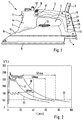
- FIG. 1 shows an embodiment of an electrically operated steam iron 1, which in the rear part of the top of its plastic housing 2 attached electrical connection line 3 can be connected to the household electricity network.
- the bow-shaped housing 2 forms a handle provided with a hollow interior 4, which forms a handle opening 5 via an internally hollow front foot 6 and a likewise hollow rear foot 7 is connected to the device base 8.
- the flat rear of the rear foot with profiling ribs is used for parking the iron in a vertical position.
- At the bottom of the apron-like down expanded base 8 is a provided with steam outlet openings, on its underside in essentially flat stainless steel soleplate 9 attached, the electric not shown Heating elements can be heated to temperatures in the range of approx. 250 ° C. Above the base there is a u.
- U. removable water tank 10 its content alternatively to generate steam escaping from the soleplate 9 or for spraying of the ironing material can be used by means of a spray nozzle 11 which is connected to a Pump operable via a depressible actuator 12 is connected.
- a thermostat is provided, the Desired temperature via an attached to the top of the water tank 10 Adjusting wheel 13 can be selected according to the type of material to be ironed.
- an essentially upright board 15 with electronic components for an electrically operable residual heat warning device 16 installed, which comprises a controllable by the circuit 15 LED 17, below a translucent plastic window 18 inside the handle 4 in front of it is defined by the grip opening 5 grip area.
- an electrically operable residual heat warning device 16 installed, which comprises a controllable by the circuit 15 LED 17, below a translucent plastic window 18 inside the handle 4 in front of it is defined by the grip opening 5 grip area.
- optical signal elements such as light-emitting diodes, also be located on other visually advantageous Places of the iron may be arranged, for example at the points marked with (*) at the rear end of the handle, at the end of the rear foot near the base or at the bottom of the iron in the area of a rear iron sole recess.
- the steam iron which is designed without a separate on / off switch, is used by inserting the plug located at the end of line 3 into a socket connected to the household electricity network and the desired temperature is determined using the setting wheel 13 set.
- the LED 17 shows, among other things, the on / off heating state of the devices, by continuous lighting or darkness.
- Sole temperature extinguishes the light emitting diode 17, which during the heating lights up evenly.
- the set temperature is, with small control deviations (Fig. 2) maintained until either the thermostat is reset or the Device is unplugged from the mains. Thereafter, the one serving as a heat-emitting element cools Soleplate exponentially, as shown schematically in the cooling curves 20, 21, 22 in Fig. 2 is shown.
- the course of the cooling curves is essential for every iron reproducible and is essentially dependent on when the heating is switched off existing starting temperature, the surface properties of the radiating iron soleplate 9, especially their size and radiation ability, the heat storage ability determining soleplate mass and the ambient temperature.
- the for a typical room temperature of 20 ° C. empirically determined cooling curves from FIG. 2 show that at a maximum position of the thermostat dial 13 corresponding output temperature of approx. 230 ° C after a cooling time of approx. 52 minutes the sole temperature to a threshold temperature indicated by the horizontal dashed line 23 has decayed from approx. 60 ° C.
- the soleplate At temperatures close to or below the threshold temperature 23 can touch the soleplate safely for a short time or with heat-sensitive ones Objects, such as plastic parts or the like, without damage in Be brought into contact.
- the corresponding cooling time is approx. 48 minutes, while at an initial temperature of approx. 100 ° C (cooling curve 22) only maximum Is 40 minutes.
- the ones with common irons and those that usually prevail Experiments carried out under ambient conditions have shown that generally at the latest After a cooling time of approx. 1 hour, the soleplate has cooled down enough no longer poses a danger.
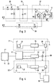
- Power supply module 25 an energy storage module 26 connected thereto and a driver module or blinking module 27 connected to this, via which the module shown in FIG. 3 LED 17 is controllable.
- One between connector AC2 and driver module 27 inserted plug-in detector module 28 causes the blinking module to be switched off 27 with plug inserted.
- the power supply 25 provides the electrical power for all components of the circuit ready.
- the resistor R1 connected to the thermostat T limits the current through the diode D2 connected between the thermostat and connection AC1, which acts as a voltage stabilizer works.
- the diode D1 connected in series with the resistor R1 leaves only that positive half-waves of the connected AC voltage.
- the between power supply facility 25 and energy storage device 26 switched diode D3 prevents the energy storage unit 26 from being discharged by the components of the power supply 25th
- the electrical energy storage device 26 essentially consists of a parallel to the terminals T and AC1 switched electrolytic capacitor HC, which acts as a high-capacity capacitor can have a capacity of approximately 0.1 farads. This can, as long as the circuit is connected to AC voltage, enough electrical energy be saved to the device for operating the light-emitting diode explained below 17 operate safely and independently of the network for periods of well over an hour to be able to.
- the storage energy is in any case dimensioned such that even with unfavorable ones Cooling conditions and highest start temperatures an operation of the warning light 17 until the iron has cooled sufficiently.
- Capacitance as an energy store enables a very simple construction in terms of circuitry of the energy store 26, since devices for charging current limitation or the like, such as they may be necessary for accumulators that are also possible, are not necessary.
- capacitors can in principle be charged any number of times without their storage capacity to change significantly, so that the life of the residual heat warning device 16 in any case can be as long as that of the iron.
- the Capacitor C1 and the resistors R2, R3 the time interval in which the LED 17 is turned off while dimensioning the capacitor C2 and the resistor R4 define the duration of the switch-on time.
- the transistors T1, T2 are used for switching between the on state and the off state.
- the resistor R5 serves to limit the current through the LED 17.
- the circuit works in such a way that when the plug is inserted or the mains voltage is switched on and closed thermostat the capacitor HC of the energy storage device 26 is charged, the light emitting diode 17 being lit. A heating up phase is thus completed Continuous lighting of the LED 17 is displayed. With the device still plugged in and open Thermostat keeps the energy storage 26 stable during the charge LED 17 is turned off. When the plug-in detector module 28 disconnects the Electrical device detected by the network takes place regardless of the position of the thermostat a discharge of the capacitor HC by the flashing device 27, which the light-emitting diode 17th operates intermittently or flashing.
- the duration of the time in which the flashing warning signal is emitted can be agreed the capacity of the memory element HC and the consumption of the light emitting diode 17th as well as the flashing device 27 provided for controlling it, for example 60 to 70 minutes to be predetermined. It is also possible to provide a time element (not shown) that causes the warning signal to be switched off after a predefinable time.
- the only time-dependent control of the warning signal can be particularly low Output temperatures mean that the warning signal is still active, although the Threshold temperature has been signed for a while. This offers additional safety margins. In any case, it is guaranteed that above the threshold temperature Warning signals are given. It is also possible to use the network-independent one Residual heat warning device with a temperature monitor of the soleplate To couple thermocouple or the like, so that a shutdown of the warning device can take place when the measured temperature falls below the threshold temperature.
- FIG. 4 is a highly schematic block diagram of another residual heat warning device 30 shown with a vertical module 31 and a horizontal module 32 of a state sensor device of the iron cooperates to deliver one of the Position and / or the movement or acceleration of the iron dependent state signal is formed, the status signal being a shutdown of the heating and / or can emit an acoustic alarm signal, for example.
- the Vertical module has a vertical sensor that can be connected to the positive pole of a DC voltage source 33, which emits a vertical signal when the iron is in a vertical position is brought, for example, where it is parked on the flat back of the rear foot 7 becomes.
- the vertical signal starts a vertical timer 34, which is predeterminable Time of 5 minutes, for example, controls a driver 35 such that the driver the power control 36 connected to the driver, the iron heating even when the plug is inserted Plug is switched off.
- the horizontal module 32 has a ground connected combined horizontal and motion sensor 37 connected to a horizontal timer 38 is connected, which also controls the power via a driver 39 36 can control.
- the circuit can be designed so that when the iron about 30 seconds unmoved in the horizontal position, via the driver 39 a switch-off signal for the heating is brought about, for example the combustion or To prevent ironing from being scorched by a carelessly forgotten iron.
- the Motion or acceleration sensor causes a reset signal as soon as that The iron is moved again, so that short breaks during ironing do not lead to a shutdown the heating.
- the residual heat warning device 30 can be constructed similarly, with suitable modifications be like the warning device 16 according to FIG. 3. It can be connected to the power supply 40 connected storage device 41 with a storage capacitor, the one connected flashing device 42 with LED 43 even when the device is unplugged or can switch off the heater with electrical energy. In contrast to the residual heat warning device 16 of FIG. 3, the residual heat warning device 30 carries the signal connected to the timers 34 and 38 of the vertical and horizontal modules, respectively.
- the circuit can be designed such that the light emitting diode 43 flashes when in the vertical position or horizontal position the corresponding module emits an alarm signal. In addition to this, the Already described alarm function can be perceived in which the light emitting diode 43 switched off heating or unplugged device is flashing as long as the Sole temperature is or could be above the threshold temperature.
- network-independent residual heat warning devices described or a corresponding type can not only be used with irons, but in general with any suitable electrical device, preferably an electrically heated one Has heat emitting body, which may damage during its cooling or could cause injury.
- any suitable electrical device preferably an electrically heated one Has heat emitting body, which may damage during its cooling or could cause injury.
- a residual heating device in particular with a capacitor as an energy store, in one Table grill, a waffle iron, an electrically operated pan or other such To provide facilities.
Landscapes
- Engineering & Computer Science (AREA)
- Textile Engineering (AREA)
- Irons (AREA)
- Soft Magnetic Materials (AREA)
- Pretreatment Of Seeds And Plants (AREA)
- Helmets And Other Head Coverings (AREA)
Abstract
Description
Eine andere, kostengünstige Möglichkeit einer netzunabhängigen Restwärmewarneinrichtung kann dadurch geschaffen werden, daß die Restwärmewarneinrichtung mindestens ein wärmeleitend mit dem Wärmeabgabeelement bzw. der Bügeleisensohle verbundenes, insbesondere direkt an diesem angebrachtes Signalelement aus einem thermisch sensitiven Material aufweist, das bei Überschreiten oder Unterschreiten des Bereichs der Schwellentemperatur eine vorzugsweise optisch wahrnehmbare Eigenschaftsänderung, insbesondere eine Farbänderung durchläuft. Das Signalelement kann insbesondere durch eine Farbschicht aus temperatursensitiver Farbe gebildet sein, die vorzugsweise seitlich am Bereich der Bügeleisensohle angebracht ist. Es ist auch möglich, im Bereich der Bügeleisensohle aus temperatursensitivem Kunststoff bestehende Teile vorzusehen, deren Aussehen sich temperaturunabhängig im Bereich der Schwellentemperatur deutlich ändert.
- Fig. 1
- eine Seitenansicht einer Ausführungsform eines erfindungsgemäßen Dampfbügeleisens mit einer Restwärmewarneinrichtung,
- Fig. 2
- drei typische Abkühlkurven für ein Bügeleisen der in Fig. 1 gezeigten Art,
- Fig. 3
- ein vereinfachtes Schaltbild einer elektronischen Schaltung der Restwärmewarneinrichtung und
- Fig. 4
- ein Blockschaltbild einer Restwärmewarneinrichtung, die mit Sensoreinrichtungen für Bügeleisenposition und -bewegung zusammenarbeitet.
Claims (23)
- Bügeleisen, insbesondere Dampfbügeleisen, mit einer elektrisch beheizbaren Bügeleisensohle, gekennzeichnet durch eine Restwärmewarneinrichtung (16; 30) zur Abgabe mindestens eines Warnsignals bei Vorliegen einer über einer Schwellentemperatur (23) liegenden Temperatur der Bügeleisensohle (9).
- Bügeleisen nach Anspruch 1, dadurch gekennzeichnet, daß die Restwärmewarneinrichtung netzunabhängig betreibbar ist.
- Bügeleisen nach Anspruch 1 oder 2, dadurch gekennzeichnet, daß an einem Gehäuse (2) eine elektrische Anschlußleitung (3) befestigt ist.
- Bügeleisen nach Anspruch 1 oder 2, dadurch gekennzeichnet, daß die Restwärmewarneinrichtung (16; 30) elektrisch betreibbar ist und daß zur Energieversorgung der Restwärmewarneinrichtung mindestens eine Speichereinrichtung (26) zur Speicherung elektrischer Energie vorgesehen ist.
- Bügeleisen nach Anspruch 4, dadurch gekennzeichnet, daß die Speichereinrichtung (26) derart geschaltet ist, daß sie bei Anschluß des Bügeleisens an eine Netzspannung aufladbar ist.
- Bügeleisen nach einem der Ansprüche 4 oder 5, dadurch gekennzeichnet, daß die Speichereinrichtung (26) mindestens einen Kondensator (HC) aufweist, vorzugsweise mindestens einen Hochkapazitätskondensator mit einer Kapazität von mehr als 0,05 Farad, insbesondere zwischen ca. 0,08 und ca. 1,2 Farad.
- Bügeleisen nach Anspruch 1 oder 2, dadurch gekennzeichnet, daß die Restwärmewarneinrichtung ausschließlich mechanisch betreibbar ist.
- Bügeleisen nach einem der vorhergehenden Ansprüche, dadurch gekennzeichnet, daß die Restwärmewarneinrichtung zur Erfassung der Temperatur der Bügeleisensohle mindestens einen mechanischen Temperatursensor aufweist, insbesondere mit mindestens einem Bimetallelement.
- Bügeleisen nach einem der vorhergehenden Ansprüche, dadurch gekennzeichnet, daß die Restwärmewarneinrichtung mindestens ein optomechanisches Signalelement aufweist, insbesondere mit mindestens einem vorzugsweise farbigen Flaggenelement.
- Bügeleisen nach einem der vorhergehenden Ansprüche, dadurch gekennzeichnet, daß der Restwärmewarneinrichtung mindestens ein Temperatursensor zur Überwachung der Temperatur der Bügeleisensohle zugeordnet ist und daß die Restwärmewarneinrichtung in Abhängigkeit eines Temperatursignals des Temperatursensor steuerbar oder gesteuert ist.
- Bügeleisen nach einem der vorhergehenden Ansprüche, dadurch gekennzeichnet, daß die Restwärmewarneinrichtung mindestens einen optischen Signalgeber aufweist, insbesondere mit mindestens einer Leuchtdiode (17), wobei vorzugsweise der optische Signalgeber intermittierend, insbesondere blinkend betreibbar ist.
- Bügeleisen nach einem der vorhergehenden Ansprüche, dadurch gekennzeichnet, daß die Restwärmewarneinrichtung derart ausgebildet ist, daß sie nach Beendigung der Beheizung der Bügeleisensohle über ein vorbestimmtes Zeitintervall ein Warnsignal abgibt wobei das vorbestimmte Zeitintervall mit einer empirisch ermittelten Abkühlzeit der Bügeleisensohle bis zu einer unkritischen, kühleren Temperatur übereinstimmt.
- Bügeleisen nach Anspruch 12, dadurch gekennzeichnet, daß die fest vorbestimmten Zeitintervalle, in denen die Restwärmewarneinrichtung das Warnsignal abgibt, abhängig von der vor Beendigung der Beheizung der Bügeleisensohle an einem Stellrad (13) zur Temperatureinstellung eingestellten Temperatur oder von einer maximal möglichen Temperatur der Bügeleisensohle sind.
- Bügeleisen nach Anspruch 12 oder 13, dadurch gekennzeichnet, daß die Restwärmewarneinrichtung ein Zeitelement aufweist, durch das die Warnsignalabgabe zeitabhängig gesteuert ist und das das vorbestimmte Zeitintervall festlegt.
- Bügeleisen nach einem der vorhergehenden Ansprüche, insbesondere nach Anspruch 12 oder 13, dadurch gekennzeichnet, daß die Restwärmewarneinrichtung keine Temperaturerfassungseinrichtung zur Erfassung der Temperatur der Bügeleisensohle aufweist, sodaß die Restwärmewarneinrichtung unabhängig von der momentanen Temperatur der Bügeleisensohle ein zu dieser Temperatur korrelierendes Warnsignal abgibt.
- Bügeleisen nach einem der vorhergehenden Ansprüche, dadurch gekennzeichnet, daß die Restwärmewarneinrichtung mindestens ein wärmeleitend mit der Bügeleisensohle verbundenes, insbesondere direkt an der Bügeleisensohle angebrachtes Signalelement aus einem thermisch sensitiven Material aufweist, das bei Überschreiten oder Unterschreiten des Bereichs der Schwellentemperatur eine vorzugsweise optisch wahrnehmbare Eigenschaftsänderung, insbesondere eine Farbänderung, durchläuft.
- Bügeleisen nach Anspruch 16, dadurch gekennzeichnet, daß das Signalelement durch eine Farbschicht gebildet ist.
- Bügeleisen nach einem der vorhergehenden Ansprüche, dadurch gekennzeichnet, daß es mindestens eine Zustandssensoreinrichtung (31, 32) aufweist, die zur Abgabe eines von der Position und/oder der Bewegung des Bügeleisens abhängigen Zustandssignals ausgebildet ist und daß die Restwärmewarneinrichtung (30) in Abhängigkeit von dem Zustandssignal betreibbar ist.
- Bügeleisen nach einem der vorhergehenden Ansprüche, dadurch gekennzeichnet, daß die Restwärmewarneinrichtung derart ausgebildet ist, daß sie nach Überschreitung einer höher als die Schwellentemperatur liegenden kritischen Temperaturschwelte auch bei nachfolgendem Unterschreiten der Schwellentemperatur ein Warnsignal abgibt.
- Bügeleisen nach einem der vorhergehenden Ansprüche, dadurch gekennzeichnet, daß die Restwärmewarneinrichtung (16) mindestens einen optischen Signalgeber (17) aufweist, der im Bereich der Oberseite des Bügeleisens (1), insbesondere an oder innerhalb eines Handgriffs (4) des Bügeleisens angeordnet ist und/oder daß mindestens ein optischer Signalgeber an der Unterseite des Bügeleisens, insbesondere neben der Bügeleisensohle (9) angeordnet ist.
- Restwärmewarneinrichtung zur Abgabe mindestens eines Warnsignal bei Vorliegen einer über einer Schwellentemperatur (23) liegenden Temperatur eines vorzugsweise elektrisch beheizbaren Wärmeabgabekörpers (9) eines Elektrogerätes, insbesondere eines Bügeleisens (1), gekennzeichnet durch die Merkmale des kennzeichnenden Teils von mindestens einem der Ansprüche 2 bis 20.
- Elektrogerät (1) mit mindestens einem vorzugsweise elektrisch beheizbaren Wärmeabgabekörper (9), gekennzeichnet durch eine netzunabhängig betreibbare Restwärmewarneinrichtung (16; 30) zur Abgabe mindestens eines Warnsignals bei Vorliegen einer über einer Schwellentemperatur liegenden Temperatur des Wärmeabgabekörpers.
- Elektrogerät nach Anspruch 21, gekennzeichnet durch die Merkmale des kennzeichnenden Teils von mindestens einem der Ansprüche 3 bis 20.
Applications Claiming Priority (2)
| Application Number | Priority Date | Filing Date | Title |
|---|---|---|---|
| DE19904815A DE19904815A1 (de) | 1999-02-05 | 1999-02-05 | Bügeleisen |
| DE19904815 | 1999-02-05 |
Publications (3)
| Publication Number | Publication Date |
|---|---|
| EP1026307A2 true EP1026307A2 (de) | 2000-08-09 |
| EP1026307A3 EP1026307A3 (de) | 2000-08-16 |
| EP1026307B1 EP1026307B1 (de) | 2004-03-31 |
Family
ID=7896611
Family Applications (1)
| Application Number | Title | Priority Date | Filing Date |
|---|---|---|---|
| EP00102333A Expired - Lifetime EP1026307B1 (de) | 1999-02-05 | 2000-02-03 | Bügeleisen |
Country Status (5)
| Country | Link |
|---|---|
| US (1) | US6548785B1 (de) |
| EP (1) | EP1026307B1 (de) |
| AT (1) | ATE263266T1 (de) |
| DE (2) | DE19904815A1 (de) |
| ES (1) | ES2218007T3 (de) |
Cited By (2)
| Publication number | Priority date | Publication date | Assignee | Title |
|---|---|---|---|---|
| US6399919B1 (en) * | 2001-07-31 | 2002-06-04 | Tsann Kuen Usa Inc. | Pressing iron capable of continued temperature status indication after power interruption |
| WO2007071517A1 (de) * | 2005-12-15 | 2007-06-28 | BSH Bosch und Siemens Hausgeräte GmbH | Schaltungsanordnung für ein peltiermodul |
Families Citing this family (11)
| Publication number | Priority date | Publication date | Assignee | Title |
|---|---|---|---|---|
| US20060076341A1 (en) * | 2004-10-08 | 2006-04-13 | Lozinski Gerald J | Pop-up auto-shutoff indicator for electric pressing irons |
| DE102006011901A1 (de) * | 2006-03-09 | 2007-09-13 | E.G.O. Elektro-Gerätebau GmbH | Restwärmeanzeige für ein Kochfeld sowie Verfahren zur Restwärmeanzeige für ein Kochfeld und Kochfeld |
| US7561058B2 (en) * | 2006-06-14 | 2009-07-14 | Fluke Corporation | Warning system and method for electrical devices |
| US20090084770A1 (en) * | 2007-09-27 | 2009-04-02 | Mei-Yueh Huang | Device to detect the position of an iron |
| US8091257B2 (en) * | 2009-03-31 | 2012-01-10 | Freescale Semiconductor, Inc. | Steam iron with acceleration and tilt detection |
| US20100257761A1 (en) * | 2009-04-08 | 2010-10-14 | Lung Wai Choi | Electric iron with a synchronizing temperature display |
| US8397406B2 (en) * | 2010-03-22 | 2013-03-19 | Sears Brands, L.L.C. | System and method for using color to indicate a state of a home appliance, such as an iron |
| TWI430094B (zh) * | 2011-09-22 | 2014-03-11 | Phison Electronics Corp | 記憶體儲存裝置、記憶體控制器與溫度管理方法 |
| US10081905B2 (en) * | 2014-01-09 | 2018-09-25 | Modiron, LLC | Ironing device |
| CN107513853A (zh) * | 2016-06-17 | 2017-12-26 | 佛山市顺德区美的电热电器制造有限公司 | 一种具有关机温度提示挂烫机及其控制方法 |
| EP3282051A1 (de) * | 2016-08-12 | 2018-02-14 | Laurastar S.A. | Bügelsystem mit assistenz |
Family Cites Families (33)
| Publication number | Priority date | Publication date | Assignee | Title |
|---|---|---|---|---|
| US204637A (en) * | 1878-06-04 | Improvement in thermometer attachments for sad-irons | ||
| US448066A (en) * | 1891-03-10 | August nicolaus | ||
| US884973A (en) * | 1907-05-16 | 1908-04-14 | Simplex Electric Heating Co | Automatic indicator or thermoscopic signal for heated tools and vessels. |
| US1280709A (en) * | 1918-01-12 | 1918-10-08 | Edward L Glass | Indicating means for electrically heating flat-irons. |
| US1403432A (en) * | 1921-04-09 | 1922-01-10 | John W Mcgilvray | Iron |
| US1491580A (en) * | 1923-04-06 | 1924-04-22 | Bognar Sandor | Temperature gauge for sadirons |
| US1577127A (en) * | 1923-10-24 | 1926-03-16 | Joseph D Kaltenback | Attachment for sadirons |
| US1625014A (en) * | 1925-04-15 | 1927-04-19 | Harry C D Annunzio | Heat indicator for heated tools |
| US1718403A (en) * | 1927-08-11 | 1929-06-25 | Bolf Joseph | Heat indicator for electric irons |
| US2201745A (en) * | 1939-03-20 | 1940-05-21 | Birtman Electric Co | Electric iron with heat indicator |
| GB566512A (en) * | 1943-04-26 | 1945-01-02 | Leonard Oswald Meyer | Improvements in or relating to temperature indicators |
| US2569259A (en) * | 1945-04-21 | 1951-09-25 | August C Purpura | Electric flatiron |
| US3827301A (en) * | 1972-09-18 | 1974-08-06 | Parker Research Robert | Fin cooled temperature sensor employing liquid crystals |
| GB2064595A (en) * | 1979-11-30 | 1981-06-17 | Bimak Srl | Adjustable temperature electric iron |
| WO1982003520A1 (en) * | 1981-04-07 | 1982-10-14 | Robert C Franklin | Appliance non-use detection safety power shut-off system |
| JPS5914898A (ja) * | 1982-07-19 | 1984-01-25 | 松下電器産業株式会社 | アイロン |
| JPS59214500A (ja) * | 1983-05-20 | 1984-12-04 | 松下電器産業株式会社 | アイロン |
| JPS61154600A (ja) * | 1984-12-26 | 1986-07-14 | 三洋電機株式会社 | アイロン |
| IT210802Z2 (it) * | 1985-12-05 | 1989-01-11 | Elettrodomus Spa | Ferro da stiro elettrico a resistenza del tipo cosiddetto senza cordone |
| JPH0632757B2 (ja) * | 1985-12-17 | 1994-05-02 | 松下電器産業株式会社 | アイロン |
| JPS6452500A (en) * | 1987-08-24 | 1989-02-28 | Matsushita Electric Industrial Co Ltd | Codeless iron |
| GB2221925A (en) * | 1988-08-16 | 1990-02-21 | Morphy Ltd Richards | Cordless iron |
| US5117092A (en) * | 1989-07-20 | 1992-05-26 | Matsushita Electric Industrial Co., Ltd. | Cordless iron |
| JPH03173600A (ja) * | 1989-12-04 | 1991-07-26 | Matsushita Electric Ind Co Ltd | 電気アイロン |
| JPH04259500A (ja) * | 1991-02-12 | 1992-09-16 | Mitsubishi Materials Corp | アイロン |
| KR100298104B1 (ko) * | 1992-12-22 | 2001-10-22 | 요트.게.아. 롤페즈 | 온도표시기를구비한열효과장치 |
| JPH07163798A (ja) * | 1993-12-15 | 1995-06-27 | Toshiba Home Technol Corp | コードレスアイロン |
| GB2289899A (en) * | 1994-05-12 | 1995-12-06 | Nicola Barry | Temperature displaying Iron |
| JP2640085B2 (ja) * | 1994-07-11 | 1997-08-13 | 三洋電機株式会社 | コードレスアイロン |
| FR2726727B1 (fr) * | 1994-11-07 | 1998-04-24 | Bosch Siemens Hausgeraete | Dispositif indicateur pour un appareil electromenager |
| KR970701812A (ko) * | 1995-01-23 | 1997-04-12 | 제이.지.에이. 롤페스 | 급냉 증기 다리미(Fast cooling steam iron) |
| JPH09168700A (ja) * | 1996-12-06 | 1997-06-30 | Sanyo Electric Co Ltd | コードレスアイロン |
| US6399919B1 (en) * | 2001-07-31 | 2002-06-04 | Tsann Kuen Usa Inc. | Pressing iron capable of continued temperature status indication after power interruption |
-
1999
- 1999-02-05 DE DE19904815A patent/DE19904815A1/de not_active Ceased
-
2000
- 2000-02-03 EP EP00102333A patent/EP1026307B1/de not_active Expired - Lifetime
- 2000-02-03 DE DE50005834T patent/DE50005834D1/de not_active Expired - Lifetime
- 2000-02-03 AT AT00102333T patent/ATE263266T1/de not_active IP Right Cessation
- 2000-02-03 ES ES00102333T patent/ES2218007T3/es not_active Expired - Lifetime
- 2000-02-04 US US09/498,548 patent/US6548785B1/en not_active Expired - Fee Related
Cited By (2)
| Publication number | Priority date | Publication date | Assignee | Title |
|---|---|---|---|---|
| US6399919B1 (en) * | 2001-07-31 | 2002-06-04 | Tsann Kuen Usa Inc. | Pressing iron capable of continued temperature status indication after power interruption |
| WO2007071517A1 (de) * | 2005-12-15 | 2007-06-28 | BSH Bosch und Siemens Hausgeräte GmbH | Schaltungsanordnung für ein peltiermodul |
Also Published As
| Publication number | Publication date |
|---|---|
| ATE263266T1 (de) | 2004-04-15 |
| US6548785B1 (en) | 2003-04-15 |
| EP1026307A3 (de) | 2000-08-16 |
| EP1026307B1 (de) | 2004-03-31 |
| DE19904815A1 (de) | 2000-08-10 |
| DE50005834D1 (de) | 2004-05-06 |
| ES2218007T3 (es) | 2004-11-16 |
Similar Documents
| Publication | Publication Date | Title |
|---|---|---|
| EP1026307B1 (de) | Bügeleisen | |
| US6756567B1 (en) | Paraffin wax warmer bath | |
| EP2505923B1 (de) | Verwendung einer sicherheitsvorrichtung bei einem elektrokochgerät | |
| NZ242552A (en) | Heat sensitive chemical dispenser; variable separation between heater and dispenser | |
| DE69423008T2 (de) | Automatische stromabschaltevorrichtung für ein elektrisches gerät | |
| DE102015101880A1 (de) | Laserbestrahlungsvorrichtung | |
| EP2347631B1 (de) | Elektrische bügelvorrichtung mit automatischem an-/abschaltungssystem | |
| CA2043482A1 (en) | Doubly-controlled aquarium safety heater | |
| US20060081589A1 (en) | Electric pressing iron with ready light and pop-up power switch | |
| DE102010012078A1 (de) | Verfahren und Anordnung zur Stabilisierung des von einer Halbleiterlichtquelle emittierten Lichtes | |
| CN201508250U (zh) | 过热检测及报警装置 | |
| DE102020134895A1 (de) | Vorrichtung zum Aussenden von elektromagnetischer Strahlung und/oder von Schallwellen | |
| EP0225298A2 (de) | Schnurloses elektrisches Bügeleisen | |
| US6399919B1 (en) | Pressing iron capable of continued temperature status indication after power interruption | |
| JP5399584B1 (ja) | 香炉用ヒーター制御装置、電気香炉及び香炉用ヒーターの制御方法 | |
| CN209562822U (zh) | 加热器 | |
| CN213273012U (zh) | 一种温控组件及加湿器 | |
| DE10200974A1 (de) | Heizvorrichtung mit flexiblem Heizkörper | |
| CN108716641B (zh) | 一种灯光控制组件和点火枪 | |
| EP1819200A2 (de) | Wärmegerät mit einem schmiegsamen Heizkörper | |
| JPS55164867A (en) | Temperature control unit | |
| CN108089614A (zh) | 一种电气控制器 | |
| DE3823636A1 (de) | Elektrische sensorschaltung | |
| GB2077958A (en) | Temperature control apparatus for animal houses | |
| DE202008002485U1 (de) | Samowar |
Legal Events
| Date | Code | Title | Description |
|---|---|---|---|
| PUAI | Public reference made under article 153(3) epc to a published international application that has entered the european phase |
Free format text: ORIGINAL CODE: 0009012 |
|
| PUAL | Search report despatched |
Free format text: ORIGINAL CODE: 0009013 |
|
| 17P | Request for examination filed |
Effective date: 20000203 |
|
| AK | Designated contracting states |
Kind code of ref document: A2 Designated state(s): AT BE CH CY DE DK ES FI FR GB GR IE IT LI LU MC NL PT SE |
|
| AX | Request for extension of the european patent |
Free format text: AL;LT;LV;MK;RO;SI |
|
| AK | Designated contracting states |
Kind code of ref document: A3 Designated state(s): AT BE CH CY DE DK ES FI FR GB GR IE IT LI LU MC NL PT SE |
|
| AX | Request for extension of the european patent |
Free format text: AL;LT;LV;MK;RO;SI |
|
| AKX | Designation fees paid |
Free format text: AT BE CH CY DE DK ES FI FR GB GR IE IT LI LU MC NL PT SE |
|
| 17Q | First examination report despatched |
Effective date: 20020910 |
|
| GRAP | Despatch of communication of intention to grant a patent |
Free format text: ORIGINAL CODE: EPIDOSNIGR1 |
|
| GRAS | Grant fee paid |
Free format text: ORIGINAL CODE: EPIDOSNIGR3 |
|
| GRAA | (expected) grant |
Free format text: ORIGINAL CODE: 0009210 |
|
| AK | Designated contracting states |
Kind code of ref document: B1 Designated state(s): AT BE CH CY DE DK ES FI FR GB GR IE IT LI LU MC NL PT SE |
|
| PG25 | Lapsed in a contracting state [announced via postgrant information from national office to epo] |
Ref country code: IE Free format text: LAPSE BECAUSE OF FAILURE TO SUBMIT A TRANSLATION OF THE DESCRIPTION OR TO PAY THE FEE WITHIN THE PRESCRIBED TIME-LIMIT Effective date: 20040331 Ref country code: FI Free format text: LAPSE BECAUSE OF FAILURE TO SUBMIT A TRANSLATION OF THE DESCRIPTION OR TO PAY THE FEE WITHIN THE PRESCRIBED TIME-LIMIT Effective date: 20040331 Ref country code: NL Free format text: LAPSE BECAUSE OF FAILURE TO SUBMIT A TRANSLATION OF THE DESCRIPTION OR TO PAY THE FEE WITHIN THE PRESCRIBED TIME-LIMIT Effective date: 20040331 |
|
| REG | Reference to a national code |
Ref country code: GB Ref legal event code: FG4D Free format text: NOT ENGLISH Ref country code: CH Ref legal event code: EP |
|
| RIN1 | Information on inventor provided before grant (corrected) |
Inventor name: CORANADO-SANZ, JUAN CARLOS Inventor name: REBORDOSA-RUIS, ANTONIO Inventor name: MARTINEZ LOPEZ, CANDELARIO Inventor name: POZO-MARIN, REMEDIOS Inventor name: VAZQUEZ, MIGUEL |
|
| GBT | Gb: translation of ep patent filed (gb section 77(6)(a)/1977) | ||
| REG | Reference to a national code |
Ref country code: IE Ref legal event code: FG4D Free format text: GERMAN |
|
| REF | Corresponds to: |
Ref document number: 50005834 Country of ref document: DE Date of ref document: 20040506 Kind code of ref document: P |
|
| REG | Reference to a national code |
Ref country code: CH Ref legal event code: NV Representative=s name: OK PAT AG PATENTE MARKEN LIZENZEN |
|
| PG25 | Lapsed in a contracting state [announced via postgrant information from national office to epo] |
Ref country code: DK Free format text: LAPSE BECAUSE OF FAILURE TO SUBMIT A TRANSLATION OF THE DESCRIPTION OR TO PAY THE FEE WITHIN THE PRESCRIBED TIME-LIMIT Effective date: 20040630 Ref country code: SE Free format text: LAPSE BECAUSE OF FAILURE TO SUBMIT A TRANSLATION OF THE DESCRIPTION OR TO PAY THE FEE WITHIN THE PRESCRIBED TIME-LIMIT Effective date: 20040630 Ref country code: GR Free format text: LAPSE BECAUSE OF FAILURE TO SUBMIT A TRANSLATION OF THE DESCRIPTION OR TO PAY THE FEE WITHIN THE PRESCRIBED TIME-LIMIT Effective date: 20040630 |
|
| NLV1 | Nl: lapsed or annulled due to failure to fulfill the requirements of art. 29p and 29m of the patents act | ||
| REG | Reference to a national code |
Ref country code: ES Ref legal event code: FG2A Ref document number: 2218007 Country of ref document: ES Kind code of ref document: T3 |
|
| REG | Reference to a national code |
Ref country code: IE Ref legal event code: FD4D |
|
| ET | Fr: translation filed | ||
| PG25 | Lapsed in a contracting state [announced via postgrant information from national office to epo] |
Ref country code: LU Free format text: LAPSE BECAUSE OF NON-PAYMENT OF DUE FEES Effective date: 20050203 Ref country code: CY Free format text: LAPSE BECAUSE OF FAILURE TO SUBMIT A TRANSLATION OF THE DESCRIPTION OR TO PAY THE FEE WITHIN THE PRESCRIBED TIME-LIMIT Effective date: 20050203 |
|
| PLBE | No opposition filed within time limit |
Free format text: ORIGINAL CODE: 0009261 |
|
| STAA | Information on the status of an ep patent application or granted ep patent |
Free format text: STATUS: NO OPPOSITION FILED WITHIN TIME LIMIT |
|
| PG25 | Lapsed in a contracting state [announced via postgrant information from national office to epo] |
Ref country code: BE Free format text: LAPSE BECAUSE OF NON-PAYMENT OF DUE FEES Effective date: 20050228 Ref country code: MC Free format text: LAPSE BECAUSE OF NON-PAYMENT OF DUE FEES Effective date: 20050228 |
|
| 26N | No opposition filed |
Effective date: 20050104 |
|
| BERE | Be: lapsed |
Owner name: *BRAUN G.M.B.H. Effective date: 20050228 |
|
| PGFP | Annual fee paid to national office [announced via postgrant information from national office to epo] |
Ref country code: AT Payment date: 20060221 Year of fee payment: 7 |
|
| PG25 | Lapsed in a contracting state [announced via postgrant information from national office to epo] |
Ref country code: AT Free format text: LAPSE BECAUSE OF NON-PAYMENT OF DUE FEES Effective date: 20070203 |
|
| BERE | Be: lapsed |
Owner name: *BRAUN G.M.B.H. Effective date: 20050228 |
|
| PG25 | Lapsed in a contracting state [announced via postgrant information from national office to epo] |
Ref country code: PT Free format text: LAPSE BECAUSE OF NON-PAYMENT OF DUE FEES Effective date: 20040831 |
|
| PGFP | Annual fee paid to national office [announced via postgrant information from national office to epo] |
Ref country code: CH Payment date: 20090226 Year of fee payment: 10 |
|
| REG | Reference to a national code |
Ref country code: CH Ref legal event code: PL |
|
| PG25 | Lapsed in a contracting state [announced via postgrant information from national office to epo] |
Ref country code: CH Free format text: LAPSE BECAUSE OF NON-PAYMENT OF DUE FEES Effective date: 20100228 Ref country code: LI Free format text: LAPSE BECAUSE OF NON-PAYMENT OF DUE FEES Effective date: 20100228 |
|
| REG | Reference to a national code |
Ref country code: FR Ref legal event code: PLFP Year of fee payment: 17 |
|
| REG | Reference to a national code |
Ref country code: FR Ref legal event code: PLFP Year of fee payment: 18 |
|
| PGFP | Annual fee paid to national office [announced via postgrant information from national office to epo] |
Ref country code: FR Payment date: 20170118 Year of fee payment: 18 |
|
| PGFP | Annual fee paid to national office [announced via postgrant information from national office to epo] |
Ref country code: GB Payment date: 20170126 Year of fee payment: 18 |
|
| PGFP | Annual fee paid to national office [announced via postgrant information from national office to epo] |
Ref country code: IT Payment date: 20170210 Year of fee payment: 18 Ref country code: ES Payment date: 20170216 Year of fee payment: 18 |
|
| PGFP | Annual fee paid to national office [announced via postgrant information from national office to epo] |
Ref country code: DE Payment date: 20180123 Year of fee payment: 19 |
|
| GBPC | Gb: european patent ceased through non-payment of renewal fee |
Effective date: 20180203 |
|
| REG | Reference to a national code |
Ref country code: FR Ref legal event code: ST Effective date: 20181031 |
|
| PG25 | Lapsed in a contracting state [announced via postgrant information from national office to epo] |
Ref country code: GB Free format text: LAPSE BECAUSE OF NON-PAYMENT OF DUE FEES Effective date: 20180203 Ref country code: FR Free format text: LAPSE BECAUSE OF NON-PAYMENT OF DUE FEES Effective date: 20180228 Ref country code: IT Free format text: LAPSE BECAUSE OF NON-PAYMENT OF DUE FEES Effective date: 20180203 |
|
| REG | Reference to a national code |
Ref country code: ES Ref legal event code: FD2A Effective date: 20190801 |
|
| REG | Reference to a national code |
Ref country code: DE Ref legal event code: R119 Ref document number: 50005834 Country of ref document: DE |
|
| PG25 | Lapsed in a contracting state [announced via postgrant information from national office to epo] |
Ref country code: ES Free format text: LAPSE BECAUSE OF NON-PAYMENT OF DUE FEES Effective date: 20180204 |
|
| PG25 | Lapsed in a contracting state [announced via postgrant information from national office to epo] |
Ref country code: DE Free format text: LAPSE BECAUSE OF NON-PAYMENT OF DUE FEES Effective date: 20190903 |