EP1024688B1 - Verfahren zum fällen von bäumen und forstwesensystem - Google Patents
Verfahren zum fällen von bäumen und forstwesensystem Download PDFInfo
- Publication number
- EP1024688B1 EP1024688B1 EP98920803A EP98920803A EP1024688B1 EP 1024688 B1 EP1024688 B1 EP 1024688B1 EP 98920803 A EP98920803 A EP 98920803A EP 98920803 A EP98920803 A EP 98920803A EP 1024688 B1 EP1024688 B1 EP 1024688B1
- Authority
- EP
- European Patent Office
- Prior art keywords
- timber
- marking
- piece
- harvesting
- information
- Prior art date
- Legal status (The legal status is an assumption and is not a legal conclusion. Google has not performed a legal analysis and makes no representation as to the accuracy of the status listed.)
- Expired - Lifetime
Links
Images


Classifications
-
- A—HUMAN NECESSITIES
- A01—AGRICULTURE; FORESTRY; ANIMAL HUSBANDRY; HUNTING; TRAPPING; FISHING
- A01G—HORTICULTURE; CULTIVATION OF VEGETABLES, FLOWERS, RICE, FRUIT, VINES, HOPS OR SEAWEED; FORESTRY; WATERING
- A01G23/00—Forestry
- A01G23/02—Transplanting, uprooting, felling or delimbing trees
- A01G23/08—Felling trees
-
- A—HUMAN NECESSITIES
- A01—AGRICULTURE; FORESTRY; ANIMAL HUSBANDRY; HUNTING; TRAPPING; FISHING
- A01G—HORTICULTURE; CULTIVATION OF VEGETABLES, FLOWERS, RICE, FRUIT, VINES, HOPS OR SEAWEED; FORESTRY; WATERING
- A01G23/00—Forestry
- A01G23/02—Transplanting, uprooting, felling or delimbing trees
- A01G23/099—Auxiliary devices, e.g. felling wedges
-
- G—PHYSICS
- G01—MEASURING; TESTING
- G01S—RADIO DIRECTION-FINDING; RADIO NAVIGATION; DETERMINING DISTANCE OR VELOCITY BY USE OF RADIO WAVES; LOCATING OR PRESENCE-DETECTING BY USE OF THE REFLECTION OR RERADIATION OF RADIO WAVES; ANALOGOUS ARRANGEMENTS USING OTHER WAVES
- G01S19/00—Satellite radio beacon positioning systems; Determining position, velocity or attitude using signals transmitted by such systems
- G01S19/01—Satellite radio beacon positioning systems transmitting time-stamped messages, e.g. GPS [Global Positioning System], GLONASS [Global Orbiting Navigation Satellite System] or GALILEO
- G01S19/13—Receivers
- G01S19/14—Receivers specially adapted for specific applications
Definitions
- the present invention relates to a method and a system for timber harvesting and forestry according to the preamble of the appended claims 1 and 15.
- EP 0535919 A2 discloses a method for identifying a penetrable member, such as a tree which is to be harvested at a future date. According to this method, a tree is provided with a passive transponder, which may accumulate information throughout the harvesting, treatment, manufacture, and installation processes that the tree would undergo in its transformation from a standing tree to an in-place pole.
- the object of the present invention is primarily to create conditions for rationalisation of forest harvesting.
- the invention aims at creating conditions to handle the wood raw material not as an anonymous bulk product but as products having an identity of origin.
- the present invention delivers the solution that in a method for forest harvesting by means of a harvesting machine comprising a vehicle and a harvesting arrangement mounted thereon the position of the harvesting machine is determined in connection to felling a tree and at least one piece of timber obtained from the tree is marked with this position information or a code by means of which the piece of timber may be associated to actual position information stored in a data base.
- the piece of timber so obtained will by this become an individual connectable to the location of growth in question, which means that the individual forest owner with certainty is able to determine if the piece of timber in question belongs to him or some other person after the transport of the piece of timber away from the very harvesting place.
- the conversion of the timber raw material from a bulk product into individuals able to be identified described above means also that not only a plurality of sellers may be comfortably kept apart with respect to their products, but a plurality of buyers may also be handled on one and the same location of harvesting.
- position information marked on a piece of timber is intended to be that exact that it shall be possible to state from exactly which tree the piece of timber emanates.
- the analysis of the timber stand taken place before the harvesting is also intended to be carried out through the remote analysis technique discussed below that precisely that the individual tree may be unambiguously determined with respect to position and also be forecasted with a rather high accuracy with respect to timber quality and volume.
- Such an accurate analysis in advance means conditions for a very accurate calculation of the yield of a certain harvesting in advance.
- the very harvesting may be very targetedly controlled so that exactly the trees to be harvested for an optimum result also really get harvested.
- a computer arrangement arranged on the harvesting machine may be adapted to control the harvesting machine on the basis of data emanating from the pre-analysis of the forest region and harvesting instructions determined on the basis thereof to only harvest exactly the trees determined in advance to be harvested.
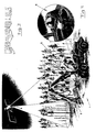
- Such a high resolution i.e. at the level of a single tree, may be achieved if an accurate registration of the forest is carried out by means of a photographical and other registration technique and these registrations are accurately co-ordinated to geographically correct conditions.
- the individual tree may also be determined with respect to position at a very high accuracy, namely in the order of centimetres or at least decimetres. It is indicated in fig. 2c how there is a tendency to apprehend the individual trees as inclining away from the centre of the picture in central projection with respect to the reproduction technique.
- a good evaluation of standing forest timber may be carried out while considering shadow effects, conicities of silhouettes of trees, diameters of leaf and needle masses, colours thereof etc. This evaluation may form a basis for very careful and exact decisions with respect to harvesting strategy.
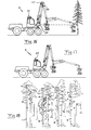
- a harvesting machine generally denominated by 1 comprising a base vehicle denominated by 2 and a harvesting arrangement 3 mounted thereon is illustrated in fig. 4.
- the harvesting arrangement 3 is in the example carried with respect to the base vehicle 2 by means of a crane 4.
- the harvesting arrangement 3 is here a so-called one grip harvesting arrangement, i.e an arrangement adapted to grip a standing tree, cut it, lay the tree down to the position according to fig. 4 and then by means of feeding means drive the log through the arrangement while simultaneously branching the log.
- the log may be cross-cut into individual pieces of timber by means of the cutting means. It is emphasised that the present invention is in this respect just as well applicable to cases in which there is a desire to abandon branching of the log, i.e.
- the invention is also applicable to so-called full log handling, i.e. where the harvesting arrangement is utilised so as to cut the tree off and fell it, but after which no cross-cutting of the log into smaller pieces is carried out.
- piece of timber used in the claims is in such a case intended to also cover the log as a whole.
- the harvesting arrangement may if desired be provided with branching means so as to relieve the log from branches by driving the log through the arrangement also in full log handling.
- a positioning determining device generally denominated by 5 is arranged on the harvesting machine and capable of determining the position of the harvesting machine by means of external signals received wirelessly.
- GPS Global Positioning System
- the satellite signals are in the reality disturbed.
- the disturbances are in the practice corrected by means of signals emitted from a ground station. These signals are received by the position determining device and may together with the satellite signals result in the very high position determining accuracy aimed at.
- a GPS-satellite is indicated by 6 in fig. 4, while an aerial of the position determining device 5 is indicated by 7.
- a computer arrangement 8 with a displaying screen which is connected to the position determining device.
- This computer may in the reality be the cross-cutting computer of the harvesting machine, provided with software and possibly hardware for the position determining treatment.
- a marking device is arranged on the harvesting machine 1.
- This device is in one embodiment illustrated in fig. 9 and is there generally indicated by 9.
- This marking device 9 is adapted to apply markings on pieces of timber obtained from trees.
- the marking device 9 is by means of the computer arrangement 8 controlled to mark the piece of timber (see for example the one indicated by 10 in fig. 8) with position information, i.e. with information about the location of growth of the tree or a code, by means of which this position information may be associated to the piece of timber in question, by means of position information received from the position determining device 5.
- position information i.e. with information about the location of growth of the tree or a code
- This code has the purpose to serve for being able to track other information, such as quality and/or size of the piece of timber, stored in the computer arrangement.
- the code in question could for instance be formed by a number in a number series, of a time information sufficiently accurate to be able to distinguish between different harvested pieces of timber etc.
- the code could also be formed by a combination of a time information and a number in a number series, in which case the number for instance could be formed by the number of the piece of timber in a tree.
- the code may serve as a basis for associating a certain piece of timber to other stored data with respect to the piece of timber, such as a position information with respect to the place of growth of the piece of timber, quality and/or size regarding the piece of timber, silvicultural or geological conditions concerning the place of growth, altitude regarding the place of growth etc.
- the altitude last mentioned concerning the place of growth may be achieved with assistance of the GPS-equipment.
- position information regarding the place of growth of the piece of timber so that, accordingly, by reading the marking the tree may be associated to the place of growth without other data having to be extracted from a data base.
- position information regarding the place of growth In case full stems are not intended to be handled, it is desirable to supplement position information regarding the place of growth with a number regarding the location of the piece of timber in question in the tree.
- the piece of timber could also be provided with further in itself readable information regarding for instance quality, size etc.
- the discharging end of the harvesting arrangement 3 is indicated in fig. 7, i.e. the end where pieces of timber are discharged by means of feeding means 11 of the arrangement.
- the arrangement has at this discharging end a cutting means 12 intended to cut off the pieces of timber fed thereto.
- the cutting means 12 is in the example a saw sword being pivotally arranged and having a chain running around. Other cutting means may of course also be possible.
- the marking device according to the invention is preferably arranged at the outlet end of the harvesting arrangement, so that a piece of timber fed thereto according to an embodiment is intended to be marked immediately after cutting it off from the rest of the log.
- the marking may be applied on the end of a piece of timber falling freely, which puts rather high demands on the velocity.
- the marking device may be adapted to apply the marking on the mantle surface of the piece of timber, possibly after relieving a portion of this mantle surface from bark.
- a possibility to carry out the marking of the piece of timber is to combine the marking device and the cutting means 12, for example by providing the cutting means 12 with marking means suitable for the purpose. These may be of contacting as well as non-contacting type.
- the marking means may according to a possible embodiment have the character of spray nozzles adapted to spray a marking having an information content already discussed above on the piece of timber just being cut. A condition for this is a comparatively large number of spray nozzles. It would in principle be possible to apply a marking having a considerable information content over the entire end of the piece of timber. A more restricted information content is of course also conceivable in particular when only a code is intended.
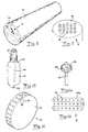
- a piece of timber 10 schematically indicated has been provided with a marking indicated by 13 and consisting of a matrix of holes punched into the end of the piece of timber.
- the marking has suitably also a reference mark 14 for enabling an adequate reading of the matrix.
- the number of possible holes in the matrix may be very large, for example 100 or more depending upon on the volume of information required. It is advantageous to apply the marking in the end surface of a piece of timber, since this would normally facilitate the following reading of the marking information.
- the marking device 9 comprises a body indicated by 15, in which a number of marking means 16 are arranged.
- These have in the example the character of punching means, which are selectively moveable between active marking positions and inactive rest positions.
- the punching means are in the example intended to be in their active positions when they are projected and in their inactive positions when they are retracted.
- these punching means are intended to be pressed against the end of the piece of timber so that the marking means active for the moment, i.e. projected, are projected into the end surface of the piece of timber.
- the harvesting organisation may be connected together to an operating centre 17, which may communicate with different units in the harvesting organisation through telephone and radio technique etc.
- the harvesting machine is indicated at 1.
- Information about the forest harvested is sent from the computer 8 thereof to the operating centre 17 and signals appropriate for controlling the harvesting work of the harvesting machine 1, for example so that the harvesting is focused upon an assortment asked for for the time being, are sent from the operating centre 17 to the harvesting machine 1.
- the operating centre 17 is for the rest in contact with other units in the harvesting organisation such as transporting vehicles and forest raw material consumers, for example sawmills and pulp industries.
- the operating centre 17 may through the GPS-system efficiently keep record of the location of the different harvesting units and efficiently plan the harvesting work.
- the operating centre 17 will at each point of time have data telling where volumes of timber are available and may be made available through harvesting, respectively, and which are the qualities and volumes considered, so that business agreements may be closed very quickly by means of the operating centre. Expressed in another way, the operating centre may function as an "electronic" timber exchange.
- the sawing intake is schematically indicated by 18.
- a reproducing device 19 is arranged in connection to the sawing intake and adapted to reproduce an end surface of the piece of timber before the sawing and register and store information in this picture with respect to shape, for example diameter and thickness of bark, and/or growth, for example annual ring widths.
- equipment included in the system may produce analyses and prognoses with respect to forest growth over the time relating to the forest region from which the pieces of timber emanate. Correction of harvesting plans may also occur.
- a condition for this is of course that a reading device 20 is present and arranged at the sawing intake to read the marking of an individual piece of timber and store the marking information.
- a computer arrangement associated with the sawmill is adapted to control an additional marking device in the sawmill to provide boards deriving from the piece of timber 10 in question with a marking in the form of a code associatable to at least information about the original location of growth of the tree. Boards may in this way be obtained, which may be checked with respect to location of growth, so that buyers having an environment consciousness may ensure that they buy boards coming from sources being acceptable from the environmental point of view.
- the reproducing device 19 and the reading device 20 may of course in the reality consist of one and the same unit.
- the marking of the piece of timber 10 and the reading of this marking makes it possible to correlate the marking with information about the real economical yield of the piece of timber after the sawing.
- Data concerning this yield and the location of growth of the piece of timber may then be compared with information already present in the forest data base, namely information initially obtained within the frame of the evaluation of standing forest timber and then information applied on the piece of timber in connection to the harvesting by means of the marking device combined with the harvesting arrangement.
- the marking means 16 has suitably a tube-like front end, which upon pressing into the wood material of the piece of timber will receive a piece of wood.
- the punching means 16 has a lateral opening 21 through which wood material entering into the tube-like end of the punching means may exit.
- the punching means 16 is rotatably arranged about an axis in parallel with the punching direction, so that accordingly the wood material entering into the punching end of the punching means may be broken apart from the piece of timber and may be brought to exit through the opening 21.
- a cam-like projecting means 22 is arranged for projecting the punching means 16 to the active position thereof, and this means is adapted to both project the punching means and make it turn.
- the projecting means 22 turns at the return movement thereof the punching means back to the starting position thereof.
- the projecting means 22 may then also be arranged to forcedly retract the punching means or as an alternative (or as a complement) a spring 23 indicated in fig. 10 may serve for the returning movement.
- the punching means 16 in fig. 10 with an ink marking, suitably by providing the punching means with an ink channel 24, through which marking ink is supplied from a source to the region of the front mouth of the punching means.
- the intention is that the hole resulting in the end of the piece of timber after punching shall be provided with ink so that this appears clearly.
- the marking means 16 consist here of a number of comparatively small drills arranged in a matrix and accordingly rotatably arranged. Each of these drills may for example be adapted to be received in a centre opening 25 of a gear denominated by 26, which on the outer side thereof has a toothing intended to engage with a cam belt 26a.
- the drills 16 and the hole 25 in the gear have engaging means preventing relative rotation of the drills with respect to the gear.
- the cam belt 27 is running in the path shown in fig. 11b, the cam belt is accordingly intended to be engaged with the different gears 26, which accordingly are rotated and the drills 16 are at the same time brought to rotate.
- the drills 16 are displaceable axially with respect to the gears 26, so that accordingly the drills desired may be brought into active marking positions by axial displacing means not illustrated in fig. 11.
- the function is then similar to that already described by means of fig. 9, i.e. the drill-like marking means 16 to be active for the moment are projected, while the other are kept retracted.
- the body 15 of the marking device has the character of a rotatable wheel.
- the marking means 16 are here radially movable, so that they may be brought to project through peripheral openings in the wheel. Accordingly actuating means are arranged inside the wheel so that the marking means 16 may selectively be brought to protrude and by that give the piece of timber in question the marking aimed at.
- the marking device according to fig. 12 could be utilised so as to mark the mantle surface of the piece of timber, possibly on a portion relieved from bark or otherwise through or on the very bark, but it would also be possible to adapt the wheel principle when marking the end surface of a piece of timber.
- a beneficial marking technique is based on the use of means emitting laser jets, which apply the marking aimed at on the log, for example in the form of a bar code or in another way.
- a number of laser marking means could be arranged in matrix form in the way already described with respect to the mechanical embodiments. Other radiant energy besides the laser technique may of course be utilised for marking purposes.
- marking device it applies the marking information required on a separate carrier, which in its turn is applied on the piece of timber.
- marking information required on a separate carrier, which in its turn is applied on the piece of timber.
- This could for example be a strip provided with marking information in the form of a bar code or another code.
- a particular cleaning equipment may be arranged at the intake to a sawmill for relieving a piece of timber from contaminations, snow or ice, which otherwise would tend to render the reading of the marking information more difficult.
- the cleaning device may for example have the character of a steam shower. In the case that marking information is only applied on the end of the wood unit it is of course sufficient to carry out the cleaning operation there.
- reading devices such as those indicated by 19 and 20 in fig. 6 may of course not only be arranged in connection to a sawmill or the like. Such reading devices could be arranged on other locations, where there is a need to assort pieces of timber depending upon the marking present thereon.
- the marking technique means in general that each individual piece of timber may be handled individually in the harvesting system described by means of fig. 5, so that a buyer accordingly has substantially better prospects of really arriving to a possession of pieces of timber best suited for his fields of use.
- a harvesting machine as before having a position determining device 5 is illustrated in fig. 14.
- the crane utilised in fig. 14 has somewhat other construction than the one illustrated in fig. 4.
- the position determining device 5 is as in the embodiment according to fig. 4 in the embodiment according to fig. 14 so designed that it has a position determining unit 27 on the vehicle, for example on the cabin being turnable in this example, while the position determining device also comprises means for determining the position of the harvesting arrangement 3 with respect to the position determining unit 27. Since the position of the unit 27 is known and the relative position of the unit 27 and the arrangement 3 may also be determined, a tree present in the arrangement 3 will accordingly also in the reality be determined with respect to position.
- the means for determining the position of the harvesting arrangement 3 with respect to the unit 27 comprise in fig. 14 a distance meter indicated by 28, for example of laser type, which is capable of measuring the distance therefrom to the log of a tree held in the arrangement 3. If this distance meter 28 is combined with angle sensors in each hinge between two mutually moveable arm parts in the crane and also a direction sensor (compass) on the crane 4 or the cabin, the distance and direction of the arrangement 3 from the unit 27 could be very accurately determined.
- the position of the arrangement 3 may then be compared with data in the computer of the harvesting machine, so that the driver could compare the actual position of the harvesting arrangement 3 with the desired position according to the harvesting instruction. The driver could by this much easier find the trees, which he has to eliminate according to the harvesting instruction.
- the very vehicle is also here intended to have a position determining unit 27 and a distance meter indicated by 28.
- the meter serves for measuring the distance between the log and a part 29 of the crane solely turnably moveable with respect to the vehicle.
- the part 29 and the vehicle cabin i.e. the part where the unit 27 is mounted
- the part 29 and the vehicle cabin are not mutually turnable but turn as a unit around a vertical axis only one sensor is required besides that, i.e a compass, for turning adjustment of the cabin/part 29.
- the part 29 would be turnable around a vertical axis with respect to the cabin an additional angle sensor would be needed between this part 29 and the rest of the vehicle.
- the position determining device 5 comprises two position determining units 27 and 27', respectively, is illustrated in fig. 16. It appears that the unit 27 is arranged on the vehicle cabin, while the unit 27' is located on the crane.
- the presence of two such position determining units, which are suitably connected to the computer arrangement 8, which is present in the harvesting machine, and capable of evaluating signals from the units for position determining purposes, means that the direction of the crane may always be determined, also during movement.
- This embodiment has as in the previous embodiment a distance meter 28.
- the only further sensing device required for unambiguously determining the position of a log present in the harvesting arrangement is an angle sensor indicated by 30 between the two outermost arm parts of the crane.
- the second position determining unit 27' should suitably not be placed too close to the harvesting arrangement since it will then be a risk that it is damaged and for the rest will be hidden by branches, needle and leaf systems.
- the alternative illustrated in fig. 17 has again a position determining device 5 with a position determining unit 27 on the vehicle cabin.
- the embodiment is in the alternative according to fig. 17 intended to be such that at each hinge connection in the crane there is an angle sensor. This is also valid for the connection between the crane and the vehicle.
- the arrangement has to be completed by a direction sensor, i.e. a compass for determining the crane direction with respect to the position determining unit 27.
- fig. 18 It is diagrammatically illustrated in fig. 18 how the distance meters 28 present in figs. 14, 15 and 16 could be brought to fulfil an additional function, namely as scanner for scanning trees to be harvested before felling the tree in question.
- a scanner for example of the laser type, is suitably connected to the control unit in the harvesting machine for supplying scanning information thereto, which is utilised by the control unit for determining cross-cutting or making a cross-cutting prognosis.
- picture information with respect to adjacent trees created by the scanner 28 may be utilised as basis for giving cross-cutting suggestions after suitable signal treatment in the computer beside the trees in question (the columns provided with numerals beside the trees in fig. 18), quality classes also being possible to state.
- the prognosis of cross-cutting determined by the scanner 28 could be compensated or adjusted by an adequate comparison with the measuring result given rise to by the previous evaluation of standing forest timber with respect to the individual tree, Thus, this means that the driver of the harvesting machine could through the computer 8 in the harvesting machine receive a substantially more refined cross-cutting suggestion from the control unit.
- the application of the invention is of course not restricted to the type of harvesting machines illustrated in the drawings. Accordingly, the invention is also applicable to such harvesting machines in which in the crane only a so called felling head is arranged, i.e a unit capable to cut off and lay down a tree, which then by means of the crane is laid into a processing machine arranged on the vehicle chassis, which normally includes both branching means and cutting means.
- a processing machine arranged on the vehicle chassis, which normally includes both branching means and cutting means.
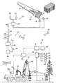
- Fig. 19 illustrates diagrammatically a possible embodiment of the invention.
- the cross-cutting computer previously described is denoted 8.
- the computer arrangement as a whole on the harvesting machine 1 is denoted 31.
- the computer arrangement comprises, apart from the cross-cutting computer 8, a further computer 32 adapted to obtain a position information corresponding to the actual position of the harvesting machine from one or two occurring GPS-units 27, 27'.
- 28 denotes one or more scanners or similar to determine the distance to and scan respectively a part of the forest stand present in front of the driver of the harvesting machine.
- 30 represents diagrammatically angle determining means etc previously discussed.
- the cross-cutting computer 8 registers quality and size regarding the pieces of timber.
- the further computer 32 establishes by means of information received from the components 27-30 the position of the harvesting arrangement.
- the computer 32 may now by means of the marking device 9 apply the previously discussed marking on the piece of timber, preferably in the form of a code.
- This code is by means of the computer 32 related to data characteristic for the piece of timber and established by the cross-cutting computer 8. These data are stored by the computer 32.
- the GPS-units 27, 27' obtain signals required for position determination from a satellite 33 or the like and additional signals required for position determination.
- the computer 32 and possibly also the cross-cutting computer 8 are adapted to communicate wirelessly, via a transmitter/receiver 34 coupled to an antenna 34a, with a transmitter/receiver 35, which also comprises an antenna 36 and is coupled to a base computer 38 included in a second computer arrangement 37.
- a transmitter/receiver 35 which also comprises an antenna 36 and is coupled to a base computer 38 included in a second computer arrangement 37.
- data are wirelessly transferable to the base computer 38 from the computer 32 on the harvesting machine.
- Data received by the base computer 38 are stored in one or more data bases belonging to one or more second computer arrangements 37. Such second computer arrangements 37 may be distributed in a suitable number over the country.
- the operating centre 17 discussed with assistance of fig. 5 is indicated as coupled to the base computer 38.
- the operating centre 17 may receive, from the base computer, data required for evaluation and control purposes.
- a forest planning unit i.e. a unit intended to feed, to the base computer 38, forest maps, harvesting plans etc. These may then be delivered to the harvesting machine wirelessly and may be used for guiding the driver of the harvesting machine, for instance via a picture screen 40 or so that the harvesting machine is automatically controlled depending upon data received.
- these data should be so accurate that the harvesting machine with guidance thereof may be moved automatically in the terrain and be caused to automatically harvest trees, which in the harvesting plan have been decided to be harvested.
- Fig. 19 also indicates that a satellite 41 may be used for providing communication between the base computer 38 and the computer arrangement 31 on the harvesting machine.
- Fig. 19 also illustrates diagrammatically a sawmill 42 having its previously discussed reproduction devices 19, 20
- the sawmill 42 is intended to comprise a third computer arrangement 43 having a computer 44.
- This receives information obtained from the reproduction devices 19, 20 and transmits this information further to the base computer 38, possibly via a wireless connection 45.
- the base computer 38 obtains from the sawmill 42 information about the timber receiving the sawmill and the properties thereof so that data stored in the base computer 38 may be supplemented and corrected respectively. This means that there are possibilities to, for instance, compare the harvesting plan with the timber gain really obtained in the sawmill so that weak links in the production chain may be identified.
- the computer 44 in the sawmill 42 may be coupled to a marking device 46 and a sorting device 47.
- Boards or groups of boards resulting in the sawmill may be provided with a marking, by means of the marking device 46, in the form a code which is associatable to data regarding place of growth for trees, from which the boards derive, quality and size information etc.
- the sorting device 47 connected to the computer 44 is intended to be controlled by the computer 44 so that boards deriving from a certain tree or a certain group of trees are brought together to a package or other board gathering so that conditions are provided to mark this gathering with a code as just described.
- the system described in fig. 19 enables continues and automatical data exchange between the computer arrangements included.
- the computer 32 on the harvesting machine besides could be able to store information regarding the place where pieces of timber have been discharged by the harvesting machine so that on subsequent fetching of those pieces of timber the driver of a forwarder via wireless transmission from the computer 32 or, if data have been transmitted to the base computer 38, from the latter may be obtained and form a basis for directing the forwarder to the place where pieces of timber are present for fetching
- the system described according to fig. 19 enables a continues harvesting direction from the operating centre 17, i.e. that the harvesting work may be directed at a very large distance from the centre.
Landscapes
- Life Sciences & Earth Sciences (AREA)
- Biodiversity & Conservation Biology (AREA)
- Ecology (AREA)
- Forests & Forestry (AREA)
- Environmental Sciences (AREA)
- Management, Administration, Business Operations System, And Electronic Commerce (AREA)
- Chemical And Physical Treatments For Wood And The Like (AREA)
- Control Of Position, Course, Altitude, Or Attitude Of Moving Bodies (AREA)
- Working Measures On Existing Buildindgs (AREA)
- Vehicle Body Suspensions (AREA)
- Guiding Agricultural Machines (AREA)
- Indicating And Signalling Devices For Elevators (AREA)
- Position Fixing By Use Of Radio Waves (AREA)
- Communication Control (AREA)
- Processing Of Stones Or Stones Resemblance Materials (AREA)
- Harvester Elements (AREA)
- Drying Of Solid Materials (AREA)
- Arrangements For Transmission Of Measured Signals (AREA)
- Combines (AREA)
- Breeding Of Plants And Reproduction By Means Of Culturing (AREA)
- Diaphragms For Electromechanical Transducers (AREA)
- Catching Or Destruction (AREA)
- Load-Engaging Elements For Cranes (AREA)
- Operation Control Of Excavators (AREA)
- Investigation Of Foundation Soil And Reinforcement Of Foundation Soil By Compacting Or Drainage (AREA)
Claims (39)
- Verfahren zur Holzernte mit Hilfe einer Erntemaschine mit einem Fahrzeug (2), einer daran angebrachten Ernteanordnung (3), einer Computeranordnung (31), die an dem Fahrzeug zur Feststellung von Qualität und/oder Größe der geernteten Holzstücke vorgesehen ist, und einer an dem Fahrzeug angebrachten Markierungsvorrichtung (9) zum Aufbringen einer Markierung (13) auf von Bäumen gewonnenen Holzstücken (10), dadurch gekennzeichnet, daß die Position der Erntemaschine mit Hilfe von mindestens einer an der Erntemaschine angeordneten Positionsbestimmungsvorrichtung bestimmt wird, wobei die Positionsbestimmungsvorrichtung (5) die Position der Erntemaschine in Zusammenhang mit dem Fällen eines Baums mit Hilfe von externen, drahtlos empfangbaren Signalen bestimmen kann, und daß mindestens ein von dem Baum gewonnenes Holzstück mit Hilfe der Markierungsvorrichtung (9, 10) mit dieser Positionsinformation oder einem Code gekennzeichnet wird, durch den das Holzstück mit Positionsinformationen zuordnenbar ist, wobei Positionsinformationen oder der Code zur Zuordnung von Daten zur Qualität und/oder Größe des betreffenden Holzstücks verwendet wird.
- Verfahren nach Anspruch 1, dadurch gekennzeichnet, daß das Holzstück auch mit Information hinsichtlich Qualität und/oder Größe versehen wird.
- Verfahren nach Anspruch 2, dadurch gekennzeichnet, daß in dem Falle, daß eine Vielzahl von Holzstücken von einem Baum gewonnen wird, jedes laufende Holzstück mit Information hinsichtlich seiner Lage an dem Holzstamm versehen wird.
- Verfahren nach einem der Ansprüche 1 bis 3, dadurch gekennzeichnet, daß Informationen hinsichtlich des Käufers und/oder Verkäufers eines einzelnen Holzstücks gespeichert sind, und daß das Holzstück mit der Information über den Käufer und/oder Verkäufer über die Positionsinformation oder den Code zugeordnet ist.
- Verfahren nach einem der Ansprüche 1 bis 4, dadurch gekennzeichnet, daß das Markieren mit Hilfe eines das Holzstück berührenden Markierungsverfahrens ausgeführt wird, beispielsweise durch Einstanzen, Schneiden, Bohren, Aufprägen etc.
- Verfahren nach einem der Ansprüche 1 bis 5, dadurch gekennzeichnet, daß das Markieren mit Hilfe eines berührungslosen Markierungsverfahrens ausgeführt wird, beispielsweise mit Strahlungsenergie, Aufsprühen von Farbe etc.
- Verfahren nach einem der Ansprüche 1 bis 6, dadurch gekennzeichnet, daß die Positionsinformation zur Erntemaschine die Position der Ernteanordnung der Erntemaschine betrifft.
- Verfahren nach einem der Ansprüche 1 bis 7, dadurch gekennzeichnet, daß das Markieren des Holzstücks an einem Ende desselben ausgeführt wird.
- Verfahren nach einem der Ansprüche 1 bis 7, dadurch gekennzeichnet, daß das Markieren an einem Abschnitt der Mantelfläche des Holzstücks ausgeführt wird, möglicherweise nachdem der Abschnitt von der Rinde befreit ist.
- Verfahren nach einem der vorangehenden Ansprüche 1 bis 9, dadurch gekennzeichnet, daß bei der Ernte festgestellte und Wachsstellen, Qualität, Größen und mögliche Lagestellen der Holzstücke in dem Raum betreffende Daten zu Auswertungszwecken gespeichert werden und mit Voraussagen hinsichtlich des Ergebnisses der Ernte verglichen werden, wobei die Voraussagen vor der Ernte gemacht wurden.
- Verfahren nach einem der vorangehenden Ansprüche, dadurch gekennzeichnet, daß eine Auswertung des stehenden Waldholzes mit Hilfe von Fernanalysen, beispielsweise durch Flugzeuge vor der Ernte hinsichtlich von einzelnen Bäumen oder relativ kleinen bewaldeten Flächen innerhalb eines Bereichs, der abgeerntet oder gelichtet werden soll, vorgenommen wird.
- Verfahren nach Anspruch 11, dadurch gekennzeichnet, daß die Ernte mit Hilfe der Bewertung des stehenden Waldholzes über von an die Erntemaschine gelieferten Daten gesteuert wird, so daß der Ernte von momentan verlangten Holzqualitäten und -größen während der Ernte Vorrang gegeben wird.
- Verfahren nach einem der Ansprüche 1 bis 12, wobei Holzstücke in einem Sägewerk zu Brettern zersägt werden, dadurch gekennzeichnet, daß in dem Sägewerk die Markierung an einem einzelnen Holzstück gelesen und gespeichert wird zusammen mit der Information über das Holzstück, so daß die Qualität und/oder Größe und/oder weitere Eigenschaften von diesem und/oder der Ertrag von dem Holzstück durch das Sägen, und daß diese Daten zur Auswertung/Korrektur der gemachten Ernteprognose verwendet werden.
- Verfahren nach einem der Ansprüche 1 bis 13, dadurch gekennzeichnet, daß mit Hilfe der Erntemaschine zu erntende Bäume vor dem Fällen des Baumes durch einen an der Erntemaschine angeordneten Scanner abgetastet werden, und daß die Abtastinformationen als Führungsmittel für die Anpassung oder eine Anpassungsvoraussage genutzt wird.
- System für die Forstwirtschaft mit Holzernte mit Hilfe einer Erntemaschine (1) mit einem Fahrzeug (2), einer an diesem angebrachten Ernteanordnung, einer an der Erntemaschine angebrachten Markierungsvorrichtung (9), wobei die Markierungsvorrichtung zum Aufbringen einer Markierung (13) auf mindestens ein Holzstück (10) angeordnet ist, und einer an der Erntemaschine angeordnete Computeranordnung (31), wobei die Computeranordnung die Markierungsvorrichtung steuern kann, um das Holzstück zu markieren, dadurch gekennzeichnet, daß an der Erntemaschine mindestens eine Positionsbestimmungsvorrichtung (5) angeordnet ist, wobei die Positionsbestimmungsvorrichtung die Position der Erntemaschine mit Hilfe von externen, drahtlos empfangbaren Signalen bestimmen kann, und daß die Computeranordnung (31) die Markierungsvorrichtung (9) steuern kann, um das Holzstück mit einer Positionsinformation oder einem Code zu versehen, durch die das Holzstück in einer Datenbank gespeicherten Positionsinformationen zugeordnet werden kann auf Grundlage von über das Positionsbestimmungsgerät (5) empfangene Positionsinformationen.
- System nach Anspruch 15, dadurch gekennzeichnet, daß die Erntemaschine Mittel zum Bestimmen/Eingeben von Information hinsichtlich der Qualität und/oder Größe des Holzstücks aufweist, und daß die Computereinrichtung (31) die Markierungsvorrichtung steuern kann, um das Holzstück mit Informationen zu Qualität und Größe versehen kann oder diese Informationen als dem Holzstück zuordbare Informationen mit Hilfe des Codes registrieren kann.
- System nach einem der Ansprüche 15 und 16, dadurch gekennzeichnet, daß die Erntemaschine Mittel zum automatischen Bestimmen/manuellen Eingeben von Informationen hinsichtlich der Lagestelle eines laufenden Holzstücks in dem Baumstamm aufweist, und daß die Computeranordnung die Markierungsvorrichtung steuern kann, um mit dieser Lageinformation zu versehen oder durch den Code diese Lageinformation als dem Holzstück zuordbar abzulegen.
- System nach einem der Ansprüche 15 bis 17, dadurch gekennzeichnet, daß die Computeranordnung Mittel zum Empfangen von Informationen hinsichtlich des Käufers und/oder des Verkäufers eines einzelnen Holzstücks aufweist, und daß die Computeranordnung die Markierungsvorrichtung steuern kann, um das Holzstück mit dieser Information zu Käufer und/oder Verkäufer zu versehen oder mit Hilfe des Codes diese Information als dem Holzstück zuordbar zu registrieren.
- System nach einem der Ansprüche 15 bis 18, dadurch gekennzeichnet, daß die Computereinrichtung vorgesehen ist, um die Position der Ernteanordnung zum Zeitpunkt des Abladens von bearbeiteten Holzstücken von der Ernteanordnung zu bestimmen und zu registrieren, und daß diese Positionsinformation in einer Datenbank oder einem Datenträger zur Verwendung bei einem nachfolgenden Aufnehmen des Holzstücks durch einen Weiterleiter zu bestimmen und zu registrieren.
- System nach einem der Ansprüche 15 bis 19, dadurch gekennzeichnet, daß die Positionsbestimmungsvorrichtung gemäß dem GPS-System (GPS = Global Positioning System) arbeitet.
- System nach einem der Ansprüche 15 bis 20, dadurch gekennzeichnet, daß die Markierungsvorrichtung (9) auf die Ernteanordnung (3) aufgebracht wird, um Holzstücke in Zusammenhang mit dem in der Ernteanordnung in Bearbeitung befindlichen Holzstamm zu markieren.
- System nach einem der Ansprüche 15 bis 21, dadurch gekennzeichnet, daß die Markierungsvorrichtung mit einem berührenden Markierungsverfahren arbeiten kann, beispielsweise mit Einstanzen, Schneiden, Bohren, Aufprägen etc.
- System nach einem der Ansprüche 15 bis 21, dadurch gekennzeichnet, daß die Markierungsvorrichtung die Holzstücke mit einem berührungslosen Markierungsverfahren markieren kann, beispielsweise mit Strahlungsenergie, beispielsweise eines Lasers, oder mit Aufsprühen von Farbe etc.
- System nach Anspruch 22, dadurch gekennzeichnet, daß die Markierungsvorrichtung eine Vielzahl von zum Berühren des Holzstücks bestimmten Markierungsmitteln (16) aufweist, wobei die Markierungsmittel wahlweise zwischen aktiven Markierungspositionen und inaktiven Ruhepositionen bewegbar sind, wodurch die beabsichtigte Markierungsinformation für das Holzstück von der Computereinrichtung abhängig von der gewünschten Markierungsinformation zusammengesetzt wird.
- System nach Anspruch 24, dadurch gekennzeichnet, daß die Markierungsmittel (16) als Einstanzmittel, Aufprägemittel oder Bohrmittel ausgebildet sind.
- System nach Anspruch 25, dadurch gekennzeichnet, daß die Markierungsvorrichtung (24) zum Zuführen von Markierungsfarbe zu den Markierungsmitteln aufweist.
- System nach Anspruch 22, dadurch gekennzeichnet, daß die Markierungsvorrichtung einen mit der Markierungsinformation versehenen Träger generieren und den Träger auf das Holzstück aufbringen kann.
- System nach Anspruch 27, dadurch gekennzeichnet, daß der Träger aus einem Klebestreifen mit der Markierungsinformation besteht, beispielsweise in Form eines Strichcodes.
- System nach Anspruch 23, dadurch gekennzeichnet, daß die Markierungsvorrichtung einen oder mehrere Laser aufweist, um die Markierungsinformation auf das Holzstück aufzubringen.
- System nach Anspruch 22, dadurch gekennzeichnet, daß die Markierungsvorrichtung einen Träger mit darauf befindlichen Markierungsmitteln umfaßt, wobei der Träger als ein sich drehendes Mittel (15) ausgebildet ist.
- Verfahren nach einem der Ansprüche 15 bis 30, dadurch gekennzeichnet, daß die Markierungsvorrichtung die Markierung an einem Ende des Holzstücks anbringen kann.
- Verfahren nach einem der Ansprüche 15 bis 30, dadurch gekennzeichnet, daß die Markierungsvorrichtung die Markierung auf einen Abschnitt der Mantelfläche des Holzstücks aufbringen kann, möglicherweise nachdem dieser Abschnitt von Rinde befreit wurde.
- Verfahren nach einem der Ansprüche 15 bis 32, dadurch gekennzeichnet, daß die zuerst genannte Computeranordnung (31) zur drahtlosen Übertragung von Daten während der Ernte an eine Datenbank (38) in einer zweiten Computeranordnung (37) übertragen kann, wobei die Daten hinsichtlich Wachsstellen, Qualität, Größe und möglicherweise Lagestellen in dem Baum der Holzstücke anschließend mit Voraussagen hinsichtlich des Ergebnisses der Ernte verglichen werden, die vor der Emte getroffen wurden.
- System nach einem der Ansprüche 15 bis 33, wobei das System eine Sägemaschine (42) zum Zersägen der Holzstücke zu Brettern aufweist, dadurch gekennzeichnet, daß ein Lesegerät (19, 20) die Markierung an einem einzelnen Holzstück vor dem Zersägen lesen und die Markierungsinformationen speichem kann, und daß eine mit der Sägemaschine verbundene dritte Computeranordnung (43) eine weitere Markierungsvorrichtung (46) steuern kann, um Bretter oder Gruppen von Brettern von dem betreffenden Holzstück mit einer Markierung zu versehen, die mindestens Informationen über die Wachsstelle des ursprünglichen Baumes enthält oder einen Code durch den diese Informationen den Brettern zugeordnet werden kann.
- System nach Anspruch 34, dadurch gekennzeichnet, daß eine Reproduktionsvorrichtung (19, 20) eine Endfläche des Holzstücks vor dem Zersägen reproduzieren kann und in dieser Reproduktion Informationen hinsichtlich der Form, beispielsweise dem Durchmesser und der Rindendicke und/oder hinsichtlich dem Wachstum, beispielsweise der Breite der Jahresringe, verzeichnen und speichern kann.
- System nach Anspruch 35, dadurch gekennzeichnet, daß es Ausrüstungen umfaßt, um mit Hilfe der Informationen hinsichtlich Form und/oder Wachstum Analysen und Voraussagen zu dem Waldwachstum über einen Zeitraum für des Waldbereichs zu generieren, aus dem die Holzstücke stammen.
- Verfahren nach einem der Ansprüche 15 bis 36, dadurch gekennzeichnet, daß an der Erntemaschine ein Scanner (28) angeordnet ist, um einen zu ernteten Baum vor dem Fällen desselben abzutasten, und daß der Scanner mit der ersten Computereinrichtung (38) verbunden ist, um die Abtastinformationen an diese zu übermitteln, wobei die Abtastinformationen als Führungsmittel für die Anpassung oder für eine Anpassungsvoraussage genutzt wird.
- System nach einem der Ansprüche 15 bis 37, dadurch gekennzeichnet, daß die Positionsbestimmungsvorrichtung (5) an der Erntemaschine mindestens eine Positionsbestimmungsvorrichtung (27) an dem Vehikel der Erntemaschine und auch auf die Erntemaschine aufgebrachte Mittel aufweist, um die Position der Ernteanordnung im Bezug auf die Positionsbestimmungseinheit zu bestimmen.
- System nach Anspruch 38, dadurch gekennzeichnet, daß die Mittel zum Bestimmen der Position der Erntemaschine im Bezug auf die Positionsbestimmungseinheit Abstandsmesser, Winkelbestimmungsmittel, Richtungsanzeiger (Kompasse) und/oder videophotogrammetrische Ausrüstungen und/oder weitere Positionsbestimmungseinheiten (27') umfaßt.
Applications Claiming Priority (4)
| Application Number | Priority Date | Filing Date | Title |
|---|---|---|---|
| SE9603880A SE9603880D0 (sv) | 1996-10-23 | 1996-10-23 | Förfarande och anordning för skoglig planering |
| WOPCT/SE97/01782 | 1997-10-23 | ||
| PCT/SE1997/001782 WO1998017099A1 (en) | 1996-10-23 | 1997-10-23 | Method for timber harvesting and system for forestry |
| PCT/SE1998/000788 WO1999023873A1 (en) | 1996-10-23 | 1998-04-28 | Method for timber harvesting and system for forestry |
Publications (2)
| Publication Number | Publication Date |
|---|---|
| EP1024688A1 EP1024688A1 (de) | 2000-08-09 |
| EP1024688B1 true EP1024688B1 (de) | 2003-04-16 |
Family
ID=20404350
Family Applications (2)
| Application Number | Title | Priority Date | Filing Date |
|---|---|---|---|
| EP97910685A Expired - Lifetime EP0957674B1 (de) | 1996-10-23 | 1997-10-23 | Holzernteverfahren und system für die forstwirtschaft |
| EP98920803A Expired - Lifetime EP1024688B1 (de) | 1996-10-23 | 1998-04-28 | Verfahren zum fällen von bäumen und forstwesensystem |
Family Applications Before (1)
| Application Number | Title | Priority Date | Filing Date |
|---|---|---|---|
| EP97910685A Expired - Lifetime EP0957674B1 (de) | 1996-10-23 | 1997-10-23 | Holzernteverfahren und system für die forstwirtschaft |
Country Status (22)
| Country | Link |
|---|---|
| US (2) | US6182725B1 (de) |
| EP (2) | EP0957674B1 (de) |
| JP (1) | JP4580100B2 (de) |
| CN (1) | CN1317941C (de) |
| AT (2) | ATE230559T1 (de) |
| AU (2) | AU727698B2 (de) |
| BR (1) | BR9814101A (de) |
| CA (2) | CA2269732C (de) |
| DE (2) | DE69718349T2 (de) |
| DK (1) | DK1024688T3 (de) |
| EA (1) | EA002229B1 (de) |
| EE (1) | EE04255B1 (de) |
| HU (1) | HUP0004041A3 (de) |
| ID (1) | ID25496A (de) |
| NO (2) | NO315921B1 (de) |
| NZ (2) | NZ335923A (de) |
| RU (1) | RU2208307C2 (de) |
| SE (1) | SE9603880D0 (de) |
| SK (1) | SK287210B6 (de) |
| TR (1) | TR200001914T2 (de) |
| UA (1) | UA59421C2 (de) |
| WO (2) | WO1998017099A1 (de) |
Cited By (1)
| Publication number | Priority date | Publication date | Assignee | Title |
|---|---|---|---|---|
| US9235334B2 (en) | 2008-05-09 | 2016-01-12 | Genesis Industries, Llc | Managing landbases and machine operations performed thereon |
Families Citing this family (109)
| Publication number | Priority date | Publication date | Assignee | Title |
|---|---|---|---|---|
| SE9603880D0 (sv) * | 1996-10-23 | 1996-10-23 | Bengt Soervik | Förfarande och anordning för skoglig planering |
| CA2287033A1 (en) * | 1999-10-21 | 2001-04-21 | Geoid Exploration Ltd. | Land-marking device and a method of land surveying and marking |
| ID28584A (id) * | 1999-12-03 | 2001-06-07 | Green Earth Ltd | Metode penebangan kayu gelondongan di hutan dan mesin untuk menjalankan metode tersebut |
| DE60104341T2 (de) * | 2000-02-23 | 2005-07-21 | Meinan Machinery Works, Inc., Ohbushi | Vorrichtung zum Erkennen von Markierungen auf gegenüberliegenden Enden eines Holzklotzes |
| SE520298C2 (sv) * | 2000-08-15 | 2003-06-24 | Bengt Soervik | Förfarande och aggregat för avverkning av skog samt system för skogsskötsel |
| SE520299C2 (sv) * | 2000-08-23 | 2003-06-24 | Bengt Soervik | Förfarande och system för hantering av virkesbitar |
| DE10123045A1 (de) * | 2001-05-11 | 2002-11-21 | Tenovis Gmbh & Co Kg | Verfahren zur Eingabe einer Rufnummer in ein Telekommunikationsgerät sowie Telekommunikationsgerät |
| SE0102772D0 (sv) * | 2001-08-21 | 2001-08-21 | Fiberpac Ab | Skogsmaskin |
| SE522906C2 (sv) | 2001-09-28 | 2004-03-16 | Telenvironment Ab | Förfarande och system för att kontrollera köttprodukters kvalitet och ursprung |
| CA2368523A1 (en) * | 2002-01-18 | 2003-07-18 | Genus Resource Management Technologies Inc. | Method and system for integrated natural resource management |
| WO2003090519A2 (en) * | 2002-04-26 | 2003-11-06 | Murcia Philippe R | Tree girding with a water jet cutter |
| US6888458B2 (en) | 2002-05-21 | 2005-05-03 | Weyerhaeuser Company | Methods for tracking silvicultural information |
| WO2004020938A1 (en) * | 2002-08-27 | 2004-03-11 | Dralle Aps | A method and a system for automatic measurement and tracking of logs, industrial wood and boards |
| US7100817B2 (en) * | 2002-09-09 | 2006-09-05 | B. R. Close | System and method of forestry management using radio frequency identification tags |
| US20040250908A1 (en) * | 2002-12-19 | 2004-12-16 | Hicks Keith B. | Method and system configured to manage a tree harvesting process |
| US20060266817A1 (en) * | 2003-08-26 | 2006-11-30 | Brad Close | System and method of forestry management using radio frequency identification tags |
| US7320349B2 (en) * | 2003-12-18 | 2008-01-22 | Caterpillar Inc. | Tree harvester |
| CA2526292C (en) * | 2004-11-09 | 2013-03-12 | Lyle Baker | Integrated mill |
| ITMI20051925A1 (it) * | 2005-10-12 | 2007-04-13 | Metapontum Agrobios S R L | Metodo per la tracciabiita' di piante |
| US20080015711A1 (en) * | 2006-06-27 | 2008-01-17 | Normand Charland | Systems and methods for forest harvest management |
| FI119962B (fi) * | 2006-08-31 | 2009-05-29 | Ponsse Oyj | Menetelmä ja sovitelma puukappaleen mittaamiseksi puunkäsittelykoneessa |
| US20080147519A1 (en) * | 2006-12-15 | 2008-06-19 | Scott Reigel | Method and System for Conducting Inventories and Appraisals |
| US20090076741A1 (en) * | 2007-09-19 | 2009-03-19 | Eb Associates, Inc. | Distributed system for measuring lumber in a sawmill |
| SE532295C2 (sv) * | 2008-04-30 | 2009-12-01 | Marie Soervik | Skördaraggregat för skogsavverkning |
| SE532659C2 (sv) * | 2008-06-11 | 2010-03-16 | Marie Soervik | Märkningsanordning och skördeaggregat |
| US20090327104A1 (en) * | 2008-06-25 | 2009-12-31 | Sanders Craig C | System for tracking and providing visibility of origin of food elements |
| RU2400971C2 (ru) * | 2008-10-29 | 2010-10-10 | Учреждение Российской академии наук Институт лесоведения РАН | Способ оценки объемного запаса круглых лесоматериалов на лесосеке по категориям крупности и расположению в стволе дерева |
| US20100332294A1 (en) * | 2009-06-29 | 2010-12-30 | Genesis Industries Llc | Method and systems for monitoring machine and operator productivity and profitability |
| DE102009051960A1 (de) * | 2009-11-04 | 2011-05-05 | Eifelwerk Heinrich Stein Gmbh & Co Kg | Erntesystem für Erntegut |
| FI20090447L (fi) * | 2009-11-26 | 2011-05-27 | Ponsse Oyj | Menetelmä ja laite metsäkoneen yhteydessä |
| RU2517863C2 (ru) * | 2010-01-12 | 2014-06-10 | СЕРВИК Мари | Маркировочное устройство и лесозаготовительный агрегат для заготовки деревьев |
| FI123208B (fi) | 2010-05-20 | 2012-12-31 | Upm Kymmene Corp | Menetelmä sekä tietojärjestelmä leimikon korjuu- ja kuljetuskelpoisuuden määrittämiseksi |
| SE534916C2 (sv) * | 2010-06-18 | 2012-02-14 | Bengt Soervik | Märkningsanordning och skördaraggregat |
| RU2468573C2 (ru) * | 2010-11-18 | 2012-12-10 | Лев Николаевич Шобанов | Способ наведения рабочего органа манипулятора лесной машины на объект |
| ITMI20110423A1 (it) * | 2011-03-16 | 2012-09-17 | Giancarlo Spezia | Procedimento e dispositivo di marcatura di coltivazioni arboree e simili |
| US8531300B2 (en) * | 2011-06-16 | 2013-09-10 | Cnh America Llc | System and method for tracking a cotton module |
| RU2478281C2 (ru) * | 2011-07-01 | 2013-04-10 | Федеральное государственное образовательное учреждение высшего профессионального образования Дальневосточный государственный аграрный университет | Пилорама ленточная самоходная |
| US20130144568A1 (en) | 2011-08-31 | 2013-06-06 | Rodrigo A. Palma-Amestoy | System and Method for Variable Detection in Objects |
| CN102506707B (zh) * | 2011-10-18 | 2013-12-25 | 北京华力兴科技发展有限责任公司 | 材积分析方法 |
| PL2584418T3 (pl) | 2011-10-21 | 2014-11-28 | Siemens Ag | Sposób i urządzenie do lokalizacji punktu zaczepienia obiektu w instalacji |
| US20130269537A1 (en) | 2012-04-16 | 2013-10-17 | Eugenio Minvielle | Conditioning system for nutritional substances |
| US8490862B1 (en) | 2012-04-16 | 2013-07-23 | Eugenio Minvielle | Transformation system for nutritional substances |
| US20130269538A1 (en) | 2012-04-16 | 2013-10-17 | Eugenio Minvielle | Transformation system for nutritional substances |
| US10219531B2 (en) | 2012-04-16 | 2019-03-05 | Iceberg Luxembourg S.A.R.L. | Preservation system for nutritional substances |
| US9541536B2 (en) | 2012-04-16 | 2017-01-10 | Eugenio Minvielle | Preservation system for nutritional substances |
| DE102012007340B4 (de) | 2012-04-13 | 2014-10-09 | Jörg Föller | Ernteanordnung sowie Verfahren zur Holzernte |
| US9460633B2 (en) | 2012-04-16 | 2016-10-04 | Eugenio Minvielle | Conditioner with sensors for nutritional substances |
| US9121840B2 (en) | 2012-04-16 | 2015-09-01 | Eugenio Minvielle | Logistic transport system for nutritional substances |
| US9069340B2 (en) | 2012-04-16 | 2015-06-30 | Eugenio Minvielle | Multi-conditioner control for conditioning nutritional substances |
| US8550365B1 (en) | 2012-04-16 | 2013-10-08 | Eugenio Minvielle | System for managing the nutritional content for nutritional substances |
| US9080997B2 (en) | 2012-04-16 | 2015-07-14 | Eugenio Minvielle | Local storage and conditioning systems for nutritional substances |
| US9016193B2 (en) | 2012-04-16 | 2015-04-28 | Eugenio Minvielle | Logistic transport system for nutritional substances |
| US9436170B2 (en) | 2012-04-16 | 2016-09-06 | Eugenio Minvielle | Appliances with weight sensors for nutritional substances |
| US9702858B1 (en) | 2012-04-16 | 2017-07-11 | Iceberg Luxembourg S.A.R.L. | Dynamic recipe control |
| US9528972B2 (en) | 2012-04-16 | 2016-12-27 | Eugenio Minvielle | Dynamic recipe control |
| US8851365B2 (en) | 2012-04-16 | 2014-10-07 | Eugenio Minvielle | Adaptive storage and conditioning systems for nutritional substances |
| US9429920B2 (en) | 2012-04-16 | 2016-08-30 | Eugenio Minvielle | Instructions for conditioning nutritional substances |
| US9072317B2 (en) | 2012-04-16 | 2015-07-07 | Eugenio Minvielle | Transformation system for nutritional substances |
| US8733631B2 (en) | 2012-04-16 | 2014-05-27 | Eugenio Minvielle | Local storage and conditioning systems for nutritional substances |
| US20140069838A1 (en) | 2012-04-16 | 2014-03-13 | Eugenio Minvielle | Nutritional Substance Label System For Adaptive Conditioning |
| US9171061B2 (en) | 2012-04-16 | 2015-10-27 | Eugenio Minvielle | Local storage and conditioning systems for nutritional substances |
| US9414623B2 (en) | 2012-04-16 | 2016-08-16 | Eugenio Minvielle | Transformation and dynamic identification system for nutritional substances |
| US9564064B2 (en) | 2012-04-16 | 2017-02-07 | Eugenio Minvielle | Conditioner with weight sensors for nutritional substances |
| RU2496303C1 (ru) * | 2012-05-03 | 2013-10-27 | Лев Николаевич Шобанов | Способ управления машиной |
| US9117185B2 (en) * | 2012-09-19 | 2015-08-25 | The Boeing Company | Forestry management system |
| AU2013203666B2 (en) * | 2012-10-10 | 2015-05-28 | Waratah Nz Limited | Method, apparatus, and system for controlling a timber-working device |
| FI20135625A7 (fi) * | 2013-06-05 | 2014-12-22 | Ponsse Oyj | Menetelmä ja sovitelma puukappaleen mittaamiseksi |
| RU2533022C1 (ru) * | 2013-06-11 | 2014-11-20 | Федеральное государственное бюджетное образовательное учреждение высшего профессионального образования "Воронежская государственная лесотехническая академия" | Способ определения запаса древостоя |
| US10790062B2 (en) | 2013-10-08 | 2020-09-29 | Eugenio Minvielle | System for tracking and optimizing health indices |
| CN103552452A (zh) * | 2013-11-08 | 2014-02-05 | 桂林福冈新材料有限公司 | 一种多功能联合采伐机 |
| RU2556070C1 (ru) * | 2013-12-24 | 2015-07-10 | Федеральное государственное бюджетное образовательное учреждение высшего профессионального образования "Поволжский государственный технологический университет" | Способ автоматизированного принятия решений по назначению деревьев в рубку при их обработке лесозаготовительной машиной |
| USD762081S1 (en) | 2014-07-29 | 2016-07-26 | Eugenio Minvielle | Device for food preservation and preparation |
| CN104122836B (zh) * | 2014-08-13 | 2017-01-11 | 北京林业大学 | 林木联合采育机作业轨迹规划与控制半实物仿真系统 |
| US10217188B2 (en) * | 2014-11-12 | 2019-02-26 | SlantRange, Inc. | Systems and methods for aggregating and facilitating the display of spatially variable geographic data acquired by airborne vehicles |
| CN104620935A (zh) * | 2015-01-26 | 2015-05-20 | 甘肃省林业科学研究院 | 一种骟树伐木方法 |
| CN104782445B (zh) * | 2015-02-13 | 2017-03-22 | 李建尧 | 一种带有报警器且通过导向槽导向的林业用伐木锯装置及其使用方法 |
| US9877437B2 (en) * | 2015-09-30 | 2018-01-30 | Deere & Company | Felled tree lean control system and method |
| JP6982571B2 (ja) * | 2016-07-15 | 2021-12-17 | 良三 松本 | 林業用ハーベスター |
| EP3296467B2 (de) * | 2016-09-20 | 2025-12-17 | BAUER Spezialtiefbau GmbH | Tiefbaugerät und tiefbauverfahren |
| CN106358983B (zh) * | 2016-10-08 | 2019-06-28 | 安徽理工大学 | 一种用于山区树木移植上的前混合磨料射流设备 |
| JP2018062069A (ja) * | 2016-10-11 | 2018-04-19 | 尾州木材工業株式会社 | 木材管理方法 |
| SE543160C2 (en) * | 2017-01-16 | 2020-10-13 | Tracy Of Sweden Ab | A method for determining and managing origin identifation of logs |
| RU2663280C1 (ru) * | 2017-06-20 | 2018-08-03 | Федеральное государственное автономное образовательное учреждение высшего образования "Северный (Арктический) федеральный университет имени М.В. Ломоносова" | Способ отвода лесосек |
| PL3424302T3 (pl) * | 2017-07-04 | 2024-03-11 | Andreas Stihl Ag & Co. Kg | Sposób ustalania orientacji co najmniej jednego odcinka ściętego drzewa oraz układ gospodarki leśnej do ustalania orientacji co najmniej jednego odcinka ściętego drzewa |
| EP3424305B1 (de) * | 2017-07-04 | 2021-05-26 | Andreas Stihl AG & Co. KG | Verfahren zum assistieren beim fällen eines baums und system zum assistieren beim fällen eines baums |
| SE542511C2 (en) * | 2017-07-07 | 2020-05-26 | Soervik Bengt | Method for handling logs and log marking tool for use in such a method |
| EP3488686A1 (de) * | 2017-11-22 | 2019-05-29 | Deere & Company | Forstmaschinenbetriebsverfahren und betriebsprozessor mit durchführung dieses verfahrens |
| CN108633533B (zh) * | 2018-04-11 | 2024-06-04 | 北京木业邦科技有限公司 | 树木自动抚育方法、装置、电子设备及存储介质 |
| US10785913B2 (en) * | 2018-04-30 | 2020-09-29 | Orchard-Rite Ltd., Inc. | Two-piece harvester having a shaker and a receiver for harvesting tree fruits or nuts |
| AT520253A3 (de) * | 2018-07-16 | 2019-04-15 | Umweltdata G M B H | Verfahren zur selektiven Holzernte |
| FI128122B (fi) * | 2018-08-29 | 2019-10-15 | Ponsse Oyj | Ohjausjärjestely ja menetelmä metsäkoneen ohjaamiseksi |
| FI20185718A1 (fi) | 2018-08-30 | 2020-03-01 | Ponsse Oyj | Menetelmä voimansiirtolaitteen ohjaamiseksi, järjestelmä ja metsäkone |
| US10905054B2 (en) * | 2018-11-13 | 2021-02-02 | Deere & Company | Controlling the operation of forestry machines based on data acquisition |
| CN109726937B (zh) * | 2019-01-25 | 2022-05-10 | 福州大学 | 基于形状测度的土地利用规划调整数据质量退化评价方法 |
| JP7135975B2 (ja) * | 2019-03-28 | 2022-09-13 | トヨタ自動車株式会社 | 伐採システムおよび伐採方法 |
| SE543307C2 (en) * | 2019-06-28 | 2020-11-24 | Deep Forestry Ab | A method for preparing for harvesting of forest using an un-manned vehicle and un-manned vehicle and system using said method |
| US11785900B2 (en) * | 2019-09-04 | 2023-10-17 | Timberpro, Inc. | Forestry machine |
| WO2021069438A1 (de) * | 2019-10-07 | 2021-04-15 | Andreas Zaglacher | Laufwagen |
| CN110956096B (zh) * | 2019-11-13 | 2024-02-23 | 北京农业智能装备技术研究中心 | 一种林业感染疫木清除管理方法及系统 |
| SE544160C2 (en) | 2020-06-15 | 2022-02-08 | Soervik Bengt | Log marking device with a setting unit for the striking head |
| JP7218941B2 (ja) * | 2020-08-07 | 2023-02-07 | 株式会社藤興業 | 間伐材等の伐倒方向の仮想空間形成方法 |
| RU2752365C1 (ru) * | 2020-11-19 | 2021-07-26 | Федеральное государственное бюджетное образовательное учреждение высшего образования "Поволжский государственный технологический университет" | Способ выборочных рубок и рубок ухода в посадках с двухрядным размещением лесных культур |
| JP7771870B2 (ja) * | 2022-05-19 | 2025-11-18 | 横河電機株式会社 | 判定装置、判定方法、および、判定プログラム |
| AT525540B1 (de) * | 2022-06-03 | 2023-05-15 | Beetle Fortech Gmbh | Markier-Vorrichtung |
| PL244049B1 (pl) * | 2023-01-06 | 2023-11-20 | Deeplai Prosta Spolka Akcyjna | Urządzenie i sposób kodowania informacji z użyciem wytłaczanych identyfikatorów |
| IT202300002823A1 (it) * | 2023-02-20 | 2024-08-20 | Sarner Sortec Srl | Metodo per il controllo e la verifica della provenienza di legno in particolare identificazione univoca dell’albero/tronco di provenienza |
| CN117237824B (zh) * | 2023-11-14 | 2024-02-02 | 吉林省林业科学研究院(吉林省林业生物防治中心站) | 一种基于遥感图像技术的林区采伐检测设备 |
| SE2430022A1 (en) * | 2024-01-21 | 2025-07-22 | Nfa Forestry Automation Ab | Improved Forest Harvester |
| JP7685307B1 (ja) * | 2024-05-21 | 2025-05-29 | 株式会社和田電業社 | 間伐システム及び間伐方法 |
Family Cites Families (19)
| Publication number | Priority date | Publication date | Assignee | Title |
|---|---|---|---|---|
| US3787700A (en) | 1971-07-27 | 1974-01-22 | Atmospheric Sciences Inc | Automatic system for measuring selected dimensions |
| FI71013C (fi) * | 1983-01-06 | 1986-10-27 | Schauman Wilh Oy | Foerfarande och anordning foer bestaemmande av en oenskad centrallinje foer cylinderlika kroppar saosom traestockar |
| DE3563887D1 (en) | 1985-05-15 | 1988-08-25 | Kajetan Latschbacher | Portable data logger |
| SE454727C (sv) * | 1986-09-30 | 1998-12-07 | Hans Dutina Research & Develop | Förfarande för bestämning av främst form och/eller läge hos långsträckta virkesstycken samt anordning för utförande av förfarandet |
| SE8702957L (sv) | 1987-07-24 | 1989-01-25 | Oesa Ab | Foerfarande vid hantering och transport av stockar fraan avverkningspldts till avnaemare jaemte landsvaegsfordon foer genomfoerande av foerfarandet |
| GB2211103A (en) * | 1987-12-18 | 1989-06-28 | Flaxman Binns Frances Julia | Toy or games equipment |
| US4947909A (en) | 1989-02-14 | 1990-08-14 | Cae Machinery Ltd. | Process and apparatus for optimizing volume of boards cut from a log |
| JPH02257280A (ja) * | 1989-03-30 | 1990-10-18 | Sumitomo Ringyo Kk | 森林データ管理方式 |
| FI86949C (fi) * | 1990-02-23 | 1992-11-10 | E P Elektroniikka Oy | Foerfarande foer maerkning av traestycken |
| CA2079517A1 (en) | 1991-10-01 | 1993-04-02 | Michael C. Ryan | Method for identifying a penetrable member |
| DE4134790A1 (de) * | 1991-10-22 | 1993-04-29 | Dietrich Gerhard Ellsaesser | Autonomes durchforstungssystem |
| DE4232412A1 (de) * | 1992-09-28 | 1994-03-31 | Dietrich Gerhard Ellsaeser | Integriertes Holzaufnahmemeßsystem |
| NZ245399A (en) * | 1993-01-14 | 1995-05-26 | Interpine Export Nz Ltd | Portable computerised log measurer |
| JP3179254B2 (ja) * | 1993-08-03 | 2001-06-25 | 日本電気株式会社 | 接近樹木離隔検出装置 |
| DE4332412C1 (de) | 1993-09-23 | 1994-12-01 | Siemens Ag | Verfahren und Schaltungsanordnung zum Schutz eines beheizten temperaturabhängigen Sensorwiderstands vor Überhitzung |
| FI952028A0 (fi) * | 1995-04-28 | 1995-04-28 | Jorma Reponen | Automatisk maetnings- och kvalifeceringsstation |
| JPH09224499A (ja) * | 1996-02-20 | 1997-09-02 | Tokimec Inc | 森林内に固定されるデータキャリア |
| DE29607860U1 (de) * | 1996-04-30 | 1996-08-22 | Pfersich, Ralph, 72474 Winterlingen | Vorrichtung zur Erfassung und Ermittlung von Kenngrößen beim Schlagen von Holz |
| SE9603880D0 (sv) * | 1996-10-23 | 1996-10-23 | Bengt Soervik | Förfarande och anordning för skoglig planering |
-
1996
- 1996-10-23 SE SE9603880A patent/SE9603880D0/xx unknown
-
1997
- 1997-10-23 AT AT97910685T patent/ATE230559T1/de not_active IP Right Cessation
- 1997-10-23 EP EP97910685A patent/EP0957674B1/de not_active Expired - Lifetime
- 1997-10-23 WO PCT/SE1997/001782 patent/WO1998017099A1/en not_active Ceased
- 1997-10-23 US US09/297,028 patent/US6182725B1/en not_active Expired - Lifetime
- 1997-10-23 DE DE69718349T patent/DE69718349T2/de not_active Expired - Fee Related
- 1997-10-23 CA CA002269732A patent/CA2269732C/en not_active Expired - Fee Related
- 1997-10-23 AU AU47986/97A patent/AU727698B2/en not_active Ceased
- 1997-10-23 RU RU99111950/13A patent/RU2208307C2/ru active
- 1997-10-23 NZ NZ335923A patent/NZ335923A/xx not_active IP Right Cessation
-
1998
- 1998-04-28 AT AT98920803T patent/ATE237220T1/de active
- 1998-04-28 UA UA2000052867A patent/UA59421C2/uk unknown
- 1998-04-28 EE EEP200000165A patent/EE04255B1/xx unknown
- 1998-04-28 ID IDW20000984D patent/ID25496A/id unknown
- 1998-04-28 SK SK569-2000A patent/SK287210B6/sk not_active IP Right Cessation
- 1998-04-28 HU HU0004041A patent/HUP0004041A3/hu unknown
- 1998-04-28 TR TR2000/01914T patent/TR200001914T2/xx unknown
- 1998-04-28 JP JP2000519989A patent/JP4580100B2/ja not_active Expired - Fee Related
- 1998-04-28 DE DE69813598T patent/DE69813598T2/de not_active Expired - Lifetime
- 1998-04-28 CA CA002309048A patent/CA2309048C/en not_active Expired - Lifetime
- 1998-04-28 EA EA200000451A patent/EA002229B1/ru not_active IP Right Cessation
- 1998-04-28 NZ NZ504489A patent/NZ504489A/xx not_active IP Right Cessation
- 1998-04-28 DK DK98920803T patent/DK1024688T3/da active
- 1998-04-28 EP EP98920803A patent/EP1024688B1/de not_active Expired - Lifetime
- 1998-04-28 WO PCT/SE1998/000788 patent/WO1999023873A1/en not_active Ceased
- 1998-04-28 CN CNB98810444XA patent/CN1317941C/zh not_active Expired - Lifetime
- 1998-04-28 US US09/529,974 patent/US6341632B1/en not_active Expired - Lifetime
- 1998-04-28 AU AU73556/98A patent/AU731574B2/en not_active Expired
- 1998-04-28 BR BR9814101-5A patent/BR9814101A/pt not_active IP Right Cessation
-
1999
- 1999-04-23 NO NO19991963A patent/NO315921B1/no not_active IP Right Cessation
-
2000
- 2000-04-17 NO NO20001996A patent/NO318508B1/no not_active IP Right Cessation
Cited By (4)
| Publication number | Priority date | Publication date | Assignee | Title |
|---|---|---|---|---|
| US9235334B2 (en) | 2008-05-09 | 2016-01-12 | Genesis Industries, Llc | Managing landbases and machine operations performed thereon |
| US9519411B2 (en) | 2008-05-09 | 2016-12-13 | Genesis Industries, Llc | Managing landbases and machine operations performed thereon |
| US10795556B2 (en) | 2008-05-09 | 2020-10-06 | Genesis Industries, Llc | Managing landbases and machine operations performed thereon |
| US11614855B2 (en) | 2008-05-09 | 2023-03-28 | Genesis Industries, Llc | Managing landbases and machine operations performed thereon |
Also Published As
Similar Documents
| Publication | Publication Date | Title |
|---|---|---|
| EP1024688B1 (de) | Verfahren zum fällen von bäumen und forstwesensystem | |
| EP1317172B1 (de) | Verfahren und system zur handhabung von holzklötzen | |
| CA2526292C (en) | Integrated mill | |
| RU99111950A (ru) | Способ лесозаготовок и система ведения лесного хозяйства | |
| AU4880599A (en) | Process for using localized agricultural data to optimize the cultivation of perennial plants | |
| US5054206A (en) | Chain saw projection mensuration method and apparatus for determining the diameter of trees | |
| EP1324650A1 (de) | Vorrichtung und verfahren bei der holzernte | |
| Ovaskainen et al. | Effect of edge trees on harvester positioning in thinning | |
| MXPA00003848A (en) | Method for timber harvesting and system for forestry | |
| CZ20001409A3 (cs) | Způsob těžby dřeva a soustava těžby v lesním hospodářství | |
| SE522055C2 (de) | ||
| FI131857B1 (fi) | Menetelmä metsätyökoneen käytössä ja metsätyökone | |
| EP4471689A1 (de) | Überwachung von geernteten stämmen und stämmestapeln an einem arbeitsort | |
| EP4495869A1 (de) | Produktionssystem und verfahren für forstwirtschaftliche anwendungen | |
| SE510426C2 (sv) | Förfarande vid sågning av timmerstockar till plank och brädor |
Legal Events
| Date | Code | Title | Description |
|---|---|---|---|
| PUAI | Public reference made under article 153(3) epc to a published international application that has entered the european phase |
Free format text: ORIGINAL CODE: 0009012 |
|
| 17P | Request for examination filed |
Effective date: 20000522 |
|
| AK | Designated contracting states |
Kind code of ref document: A1 Designated state(s): AT BE CH CY DE DK ES FI FR GB GR IE IT LI NL PT SE |
|
| AX | Request for extension of the european patent |
Free format text: AL PAYMENT 20000522;LT PAYMENT 20000522;LV PAYMENT 20000522;MK PAYMENT 20000522;RO PAYMENT 20000522;SI PAYMENT 20000522 |
|
| RIC1 | Information provided on ipc code assigned before grant |
Free format text: 7A 01G 23/08 A |
|
| 17Q | First examination report despatched |
Effective date: 20020131 |
|
| GRAH | Despatch of communication of intention to grant a patent |
Free format text: ORIGINAL CODE: EPIDOS IGRA |
|
| GRAH | Despatch of communication of intention to grant a patent |
Free format text: ORIGINAL CODE: EPIDOS IGRA |
|
| GRAA | (expected) grant |
Free format text: ORIGINAL CODE: 0009210 |
|
| AK | Designated contracting states |
Designated state(s): AT BE CH CY DE DK ES FI FR GB GR IE IT LI NL PT SE |
|
| AX | Request for extension of the european patent |
Extension state: AL LT LV MK RO SI |
|
| PG25 | Lapsed in a contracting state [announced via postgrant information from national office to epo] |
Ref country code: NL Free format text: LAPSE BECAUSE OF FAILURE TO SUBMIT A TRANSLATION OF THE DESCRIPTION OR TO PAY THE FEE WITHIN THE PRESCRIBED TIME-LIMIT Effective date: 20030416 Ref country code: LI Free format text: LAPSE BECAUSE OF FAILURE TO SUBMIT A TRANSLATION OF THE DESCRIPTION OR TO PAY THE FEE WITHIN THE PRESCRIBED TIME-LIMIT Effective date: 20030416 Ref country code: IT Free format text: LAPSE BECAUSE OF FAILURE TO SUBMIT A TRANSLATION OF THE DESCRIPTION OR TO PAY THE FEE WITHIN THE PRESCRIBED TIME-LIMIT;WARNING: LAPSES OF ITALIAN PATENTS WITH EFFECTIVE DATE BEFORE 2007 MAY HAVE OCCURRED AT ANY TIME BEFORE 2007. THE CORRECT EFFECTIVE DATE MAY BE DIFFERENT FROM THE ONE RECORDED. Effective date: 20030416 Ref country code: CH Free format text: LAPSE BECAUSE OF FAILURE TO SUBMIT A TRANSLATION OF THE DESCRIPTION OR TO PAY THE FEE WITHIN THE PRESCRIBED TIME-LIMIT Effective date: 20030416 Ref country code: BE Free format text: LAPSE BECAUSE OF FAILURE TO SUBMIT A TRANSLATION OF THE DESCRIPTION OR TO PAY THE FEE WITHIN THE PRESCRIBED TIME-LIMIT Effective date: 20030416 |
|
| REG | Reference to a national code |
Ref country code: GB Ref legal event code: FG4D |
|
| PG25 | Lapsed in a contracting state [announced via postgrant information from national office to epo] |
Ref country code: CY Free format text: LAPSE BECAUSE OF FAILURE TO SUBMIT A TRANSLATION OF THE DESCRIPTION OR TO PAY THE FEE WITHIN THE PRESCRIBED TIME-LIMIT Effective date: 20030428 |
|
| REG | Reference to a national code |
Ref country code: CH Ref legal event code: EP |
|
| REF | Corresponds to: |
Ref document number: 69813598 Country of ref document: DE Date of ref document: 20030522 Kind code of ref document: P |
|
| REG | Reference to a national code |
Ref country code: IE Ref legal event code: FG4D |
|
| PG25 | Lapsed in a contracting state [announced via postgrant information from national office to epo] |
Ref country code: SE Free format text: LAPSE BECAUSE OF FAILURE TO SUBMIT A TRANSLATION OF THE DESCRIPTION OR TO PAY THE FEE WITHIN THE PRESCRIBED TIME-LIMIT Effective date: 20030716 Ref country code: PT Free format text: LAPSE BECAUSE OF FAILURE TO SUBMIT A TRANSLATION OF THE DESCRIPTION OR TO PAY THE FEE WITHIN THE PRESCRIBED TIME-LIMIT Effective date: 20030716 Ref country code: GR Free format text: LAPSE BECAUSE OF FAILURE TO SUBMIT A TRANSLATION OF THE DESCRIPTION OR TO PAY THE FEE WITHIN THE PRESCRIBED TIME-LIMIT Effective date: 20030716 |
|
| REG | Reference to a national code |
Ref country code: DK Ref legal event code: T3 |
|
| NLV1 | Nl: lapsed or annulled due to failure to fulfill the requirements of art. 29p and 29m of the patents act | ||
| PG25 | Lapsed in a contracting state [announced via postgrant information from national office to epo] |
Ref country code: ES Free format text: LAPSE BECAUSE OF FAILURE TO SUBMIT A TRANSLATION OF THE DESCRIPTION OR TO PAY THE FEE WITHIN THE PRESCRIBED TIME-LIMIT Effective date: 20031030 |
|
| REG | Reference to a national code |
Ref country code: CH Ref legal event code: PL |
|
| ET | Fr: translation filed | ||
| PLBE | No opposition filed within time limit |
Free format text: ORIGINAL CODE: 0009261 |
|
| STAA | Information on the status of an ep patent application or granted ep patent |
Free format text: STATUS: NO OPPOSITION FILED WITHIN TIME LIMIT |
|
| 26N | No opposition filed |
Effective date: 20040119 |
|
| PGFP | Annual fee paid to national office [announced via postgrant information from national office to epo] |
Ref country code: IE Payment date: 20101029 Year of fee payment: 13 |
|
| REG | Reference to a national code |
Ref country code: IE Ref legal event code: MM4A |
|
| PG25 | Lapsed in a contracting state [announced via postgrant information from national office to epo] |
Ref country code: IE Free format text: LAPSE BECAUSE OF NON-PAYMENT OF DUE FEES Effective date: 20110428 |
|
| REG | Reference to a national code |
Ref country code: FR Ref legal event code: PLFP Year of fee payment: 18 |
|
| REG | Reference to a national code |
Ref country code: FR Ref legal event code: PLFP Year of fee payment: 19 |
|
| PGFP | Annual fee paid to national office [announced via postgrant information from national office to epo] |
Ref country code: DE Payment date: 20161028 Year of fee payment: 19 Ref country code: DK Payment date: 20161028 Year of fee payment: 19 Ref country code: FR Payment date: 20161028 Year of fee payment: 19 Ref country code: GB Payment date: 20161028 Year of fee payment: 19 |
|
| PGFP | Annual fee paid to national office [announced via postgrant information from national office to epo] |
Ref country code: AT Payment date: 20161031 Year of fee payment: 19 |
|
| REG | Reference to a national code |
Ref country code: DE Ref legal event code: R119 Ref document number: 69813598 Country of ref document: DE |
|
| REG | Reference to a national code |
Ref country code: DK Ref legal event code: EBP Effective date: 20170430 |
|
| REG | Reference to a national code |
Ref country code: LT Ref legal event code: MM9D Effective date: 20170428 |
|
| REG | Reference to a national code |
Ref country code: AT Ref legal event code: MM01 Ref document number: 237220 Country of ref document: AT Kind code of ref document: T Effective date: 20170428 |
|
| GBPC | Gb: european patent ceased through non-payment of renewal fee |
Effective date: 20170428 |
|
| REG | Reference to a national code |
Ref country code: FR Ref legal event code: ST Effective date: 20171229 |
|
| PG25 | Lapsed in a contracting state [announced via postgrant information from national office to epo] |
Ref country code: DE Free format text: LAPSE BECAUSE OF NON-PAYMENT OF DUE FEES Effective date: 20171103 Ref country code: AT Free format text: LAPSE BECAUSE OF NON-PAYMENT OF DUE FEES Effective date: 20170428 Ref country code: FR Free format text: LAPSE BECAUSE OF NON-PAYMENT OF DUE FEES Effective date: 20170502 |
|
| PGFP | Annual fee paid to national office [announced via postgrant information from national office to epo] |
Ref country code: FI Payment date: 20171030 Year of fee payment: 20 |
|
| PG25 | Lapsed in a contracting state [announced via postgrant information from national office to epo] |
Ref country code: GB Free format text: LAPSE BECAUSE OF NON-PAYMENT OF DUE FEES Effective date: 20170428 |
|
| PG25 | Lapsed in a contracting state [announced via postgrant information from national office to epo] |
Ref country code: DK Free format text: LAPSE BECAUSE OF NON-PAYMENT OF DUE FEES Effective date: 20170430 |