EP1021320B1 - Easy ejector seat and indo-skeletal crash safety beam - Google Patents
Easy ejector seat and indo-skeletal crash safety beam Download PDFInfo
- Publication number
- EP1021320B1 EP1021320B1 EP98948260A EP98948260A EP1021320B1 EP 1021320 B1 EP1021320 B1 EP 1021320B1 EP 98948260 A EP98948260 A EP 98948260A EP 98948260 A EP98948260 A EP 98948260A EP 1021320 B1 EP1021320 B1 EP 1021320B1
- Authority
- EP
- European Patent Office
- Prior art keywords
- seat
- structure according
- vehicle
- impact
- passenger
- Prior art date
- Legal status (The legal status is an assumption and is not a legal conclusion. Google has not performed a legal analysis and makes no representation as to the accuracy of the status listed.)
- Expired - Lifetime
Links
- 230000035939 shock Effects 0.000 claims description 35
- 230000001012 protector Effects 0.000 claims description 32
- 230000033001 locomotion Effects 0.000 claims description 26
- 230000007246 mechanism Effects 0.000 claims description 19
- 230000005484 gravity Effects 0.000 claims description 11
- 208000027418 Wounds and injury Diseases 0.000 claims description 9
- 230000006378 damage Effects 0.000 claims description 9
- 208000014674 injury Diseases 0.000 claims description 9
- 239000000463 material Substances 0.000 claims description 6
- 230000008878 coupling Effects 0.000 claims description 3
- 238000010168 coupling process Methods 0.000 claims description 3
- 238000005859 coupling reaction Methods 0.000 claims description 3
- 238000000034 method Methods 0.000 claims description 3
- 238000010304 firing Methods 0.000 claims 1
- 230000008685 targeting Effects 0.000 abstract 1
- 238000013461 design Methods 0.000 description 37
- 239000006096 absorbing agent Substances 0.000 description 30
- 239000011257 shell material Substances 0.000 description 10
- 230000001133 acceleration Effects 0.000 description 8
- 230000009977 dual effect Effects 0.000 description 6
- 238000012546 transfer Methods 0.000 description 6
- 230000006835 compression Effects 0.000 description 5
- 238000007906 compression Methods 0.000 description 5
- 238000013459 approach Methods 0.000 description 4
- 230000037396 body weight Effects 0.000 description 4
- 230000001681 protective effect Effects 0.000 description 4
- 238000005452 bending Methods 0.000 description 3
- 239000002537 cosmetic Substances 0.000 description 3
- 239000004677 Nylon Substances 0.000 description 2
- 230000009471 action Effects 0.000 description 2
- 238000010276 construction Methods 0.000 description 2
- 230000001419 dependent effect Effects 0.000 description 2
- 230000000670 limiting effect Effects 0.000 description 2
- 229920001778 nylon Polymers 0.000 description 2
- 230000002459 sustained effect Effects 0.000 description 2
- 238000004804 winding Methods 0.000 description 2
- 208000025962 Crush injury Diseases 0.000 description 1
- 241001465754 Metazoa Species 0.000 description 1
- 238000007792 addition Methods 0.000 description 1
- 230000026058 directional locomotion Effects 0.000 description 1
- 230000000694 effects Effects 0.000 description 1
- 238000005265 energy consumption Methods 0.000 description 1
- 239000007789 gas Substances 0.000 description 1
- 239000001307 helium Substances 0.000 description 1
- 229910052734 helium Inorganic materials 0.000 description 1
- SWQJXJOGLNCZEY-UHFFFAOYSA-N helium atom Chemical compound [He] SWQJXJOGLNCZEY-UHFFFAOYSA-N 0.000 description 1
- 230000003116 impacting effect Effects 0.000 description 1
- 239000003562 lightweight material Substances 0.000 description 1
- 238000012986 modification Methods 0.000 description 1
- 230000004048 modification Effects 0.000 description 1
- 230000002265 prevention Effects 0.000 description 1
- 230000008569 process Effects 0.000 description 1
- 230000002441 reversible effect Effects 0.000 description 1
- 238000012800 visualization Methods 0.000 description 1
Images


Classifications
-
- B—PERFORMING OPERATIONS; TRANSPORTING
- B60—VEHICLES IN GENERAL
- B60N—SEATS SPECIALLY ADAPTED FOR VEHICLES; VEHICLE PASSENGER ACCOMMODATION NOT OTHERWISE PROVIDED FOR
- B60N2/00—Seats specially adapted for vehicles; Arrangement or mounting of seats in vehicles
- B60N2/24—Seats specially adapted for vehicles; Arrangement or mounting of seats in vehicles for particular purposes or particular vehicles
- B60N2/42—Seats specially adapted for vehicles; Arrangement or mounting of seats in vehicles for particular purposes or particular vehicles the seat constructed to protect the occupant from the effect of abnormal g-forces, e.g. crash or safety seats
- B60N2/4207—Seats specially adapted for vehicles; Arrangement or mounting of seats in vehicles for particular purposes or particular vehicles the seat constructed to protect the occupant from the effect of abnormal g-forces, e.g. crash or safety seats characterised by the direction of the g-forces
- B60N2/4214—Seats specially adapted for vehicles; Arrangement or mounting of seats in vehicles for particular purposes or particular vehicles the seat constructed to protect the occupant from the effect of abnormal g-forces, e.g. crash or safety seats characterised by the direction of the g-forces longitudinal
- B60N2/4221—Seats specially adapted for vehicles; Arrangement or mounting of seats in vehicles for particular purposes or particular vehicles the seat constructed to protect the occupant from the effect of abnormal g-forces, e.g. crash or safety seats characterised by the direction of the g-forces longitudinal due to impact coming from the front
-
- B—PERFORMING OPERATIONS; TRANSPORTING
- B60—VEHICLES IN GENERAL
- B60N—SEATS SPECIALLY ADAPTED FOR VEHICLES; VEHICLE PASSENGER ACCOMMODATION NOT OTHERWISE PROVIDED FOR
- B60N2/00—Seats specially adapted for vehicles; Arrangement or mounting of seats in vehicles
- B60N2/02—Seats specially adapted for vehicles; Arrangement or mounting of seats in vehicles the seat or part thereof being movable, e.g. adjustable
- B60N2/04—Seats specially adapted for vehicles; Arrangement or mounting of seats in vehicles the seat or part thereof being movable, e.g. adjustable the whole seat being movable
- B60N2/06—Seats specially adapted for vehicles; Arrangement or mounting of seats in vehicles the seat or part thereof being movable, e.g. adjustable the whole seat being movable slidable
- B60N2/062—Seats specially adapted for vehicles; Arrangement or mounting of seats in vehicles the seat or part thereof being movable, e.g. adjustable the whole seat being movable slidable transversally slidable
-
- B—PERFORMING OPERATIONS; TRANSPORTING
- B60—VEHICLES IN GENERAL
- B60N—SEATS SPECIALLY ADAPTED FOR VEHICLES; VEHICLE PASSENGER ACCOMMODATION NOT OTHERWISE PROVIDED FOR
- B60N2/00—Seats specially adapted for vehicles; Arrangement or mounting of seats in vehicles
- B60N2/24—Seats specially adapted for vehicles; Arrangement or mounting of seats in vehicles for particular purposes or particular vehicles
- B60N2/245—Seats specially adapted for vehicles; Arrangement or mounting of seats in vehicles for particular purposes or particular vehicles for handicapped persons
-
- B—PERFORMING OPERATIONS; TRANSPORTING
- B60—VEHICLES IN GENERAL
- B60N—SEATS SPECIALLY ADAPTED FOR VEHICLES; VEHICLE PASSENGER ACCOMMODATION NOT OTHERWISE PROVIDED FOR
- B60N2/00—Seats specially adapted for vehicles; Arrangement or mounting of seats in vehicles
- B60N2/24—Seats specially adapted for vehicles; Arrangement or mounting of seats in vehicles for particular purposes or particular vehicles
- B60N2/42—Seats specially adapted for vehicles; Arrangement or mounting of seats in vehicles for particular purposes or particular vehicles the seat constructed to protect the occupant from the effect of abnormal g-forces, e.g. crash or safety seats
- B60N2/4207—Seats specially adapted for vehicles; Arrangement or mounting of seats in vehicles for particular purposes or particular vehicles the seat constructed to protect the occupant from the effect of abnormal g-forces, e.g. crash or safety seats characterised by the direction of the g-forces
- B60N2/4214—Seats specially adapted for vehicles; Arrangement or mounting of seats in vehicles for particular purposes or particular vehicles the seat constructed to protect the occupant from the effect of abnormal g-forces, e.g. crash or safety seats characterised by the direction of the g-forces longitudinal
-
- B—PERFORMING OPERATIONS; TRANSPORTING
- B60—VEHICLES IN GENERAL
- B60N—SEATS SPECIALLY ADAPTED FOR VEHICLES; VEHICLE PASSENGER ACCOMMODATION NOT OTHERWISE PROVIDED FOR
- B60N2/00—Seats specially adapted for vehicles; Arrangement or mounting of seats in vehicles
- B60N2/24—Seats specially adapted for vehicles; Arrangement or mounting of seats in vehicles for particular purposes or particular vehicles
- B60N2/42—Seats specially adapted for vehicles; Arrangement or mounting of seats in vehicles for particular purposes or particular vehicles the seat constructed to protect the occupant from the effect of abnormal g-forces, e.g. crash or safety seats
- B60N2/4207—Seats specially adapted for vehicles; Arrangement or mounting of seats in vehicles for particular purposes or particular vehicles the seat constructed to protect the occupant from the effect of abnormal g-forces, e.g. crash or safety seats characterised by the direction of the g-forces
- B60N2/4235—Seats specially adapted for vehicles; Arrangement or mounting of seats in vehicles for particular purposes or particular vehicles the seat constructed to protect the occupant from the effect of abnormal g-forces, e.g. crash or safety seats characterised by the direction of the g-forces transversal
-
- B—PERFORMING OPERATIONS; TRANSPORTING
- B60—VEHICLES IN GENERAL
- B60N—SEATS SPECIALLY ADAPTED FOR VEHICLES; VEHICLE PASSENGER ACCOMMODATION NOT OTHERWISE PROVIDED FOR
- B60N2/00—Seats specially adapted for vehicles; Arrangement or mounting of seats in vehicles
- B60N2/24—Seats specially adapted for vehicles; Arrangement or mounting of seats in vehicles for particular purposes or particular vehicles
- B60N2/42—Seats specially adapted for vehicles; Arrangement or mounting of seats in vehicles for particular purposes or particular vehicles the seat constructed to protect the occupant from the effect of abnormal g-forces, e.g. crash or safety seats
- B60N2/427—Seats or parts thereof displaced during a crash
- B60N2/42727—Seats or parts thereof displaced during a crash involving substantially rigid displacement
- B60N2/42736—Seats or parts thereof displaced during a crash involving substantially rigid displacement of the whole seat
-
- B—PERFORMING OPERATIONS; TRANSPORTING
- B60—VEHICLES IN GENERAL
- B60N—SEATS SPECIALLY ADAPTED FOR VEHICLES; VEHICLE PASSENGER ACCOMMODATION NOT OTHERWISE PROVIDED FOR
- B60N2/00—Seats specially adapted for vehicles; Arrangement or mounting of seats in vehicles
- B60N2/24—Seats specially adapted for vehicles; Arrangement or mounting of seats in vehicles for particular purposes or particular vehicles
- B60N2/42—Seats specially adapted for vehicles; Arrangement or mounting of seats in vehicles for particular purposes or particular vehicles the seat constructed to protect the occupant from the effect of abnormal g-forces, e.g. crash or safety seats
- B60N2/427—Seats or parts thereof displaced during a crash
- B60N2/42772—Seats or parts thereof displaced during a crash characterised by the triggering system
- B60N2/4279—Seats or parts thereof displaced during a crash characterised by the triggering system electric or electronic triggering
-
- B—PERFORMING OPERATIONS; TRANSPORTING
- B62—LAND VEHICLES FOR TRAVELLING OTHERWISE THAN ON RAILS
- B62D—MOTOR VEHICLES; TRAILERS
- B62D21/00—Understructures, i.e. chassis frame on which a vehicle body may be mounted
- B62D21/15—Understructures, i.e. chassis frame on which a vehicle body may be mounted having impact absorbing means, e.g. a frame designed to permanently or temporarily change shape or dimension upon impact with another body
- B62D21/157—Understructures, i.e. chassis frame on which a vehicle body may be mounted having impact absorbing means, e.g. a frame designed to permanently or temporarily change shape or dimension upon impact with another body for side impacts
-
- A—HUMAN NECESSITIES
- A61—MEDICAL OR VETERINARY SCIENCE; HYGIENE
- A61G—TRANSPORT, PERSONAL CONVEYANCES, OR ACCOMMODATION SPECIALLY ADAPTED FOR PATIENTS OR DISABLED PERSONS; OPERATING TABLES OR CHAIRS; CHAIRS FOR DENTISTRY; FUNERAL DEVICES
- A61G2203/00—General characteristics of devices
- A61G2203/70—General characteristics of devices with special adaptations, e.g. for safety or comfort
- A61G2203/72—General characteristics of devices with special adaptations, e.g. for safety or comfort for collision prevention
- A61G2203/723—Impact absorbing means, e.g. bumpers or airbags
-
- B—PERFORMING OPERATIONS; TRANSPORTING
- B60—VEHICLES IN GENERAL
- B60R—VEHICLES, VEHICLE FITTINGS, OR VEHICLE PARTS, NOT OTHERWISE PROVIDED FOR
- B60R19/00—Wheel guards; Radiator guards, e.g. grilles; Obstruction removers; Fittings damping bouncing force in collisions
- B60R19/02—Bumpers, i.e. impact receiving or absorbing members for protecting vehicles or fending off blows from other vehicles or objects
- B60R19/18—Bumpers, i.e. impact receiving or absorbing members for protecting vehicles or fending off blows from other vehicles or objects characterised by the cross-section; Means within the bumper to absorb impact
- B60R19/20—Bumpers, i.e. impact receiving or absorbing members for protecting vehicles or fending off blows from other vehicles or objects characterised by the cross-section; Means within the bumper to absorb impact containing mainly gas or liquid, e.g. inflatable
- B60R19/205—Bumpers, i.e. impact receiving or absorbing members for protecting vehicles or fending off blows from other vehicles or objects characterised by the cross-section; Means within the bumper to absorb impact containing mainly gas or liquid, e.g. inflatable inflatable in the direction of an obstacle upon impending impact, e.g. using air bags
-
- B—PERFORMING OPERATIONS; TRANSPORTING
- B60—VEHICLES IN GENERAL
- B60R—VEHICLES, VEHICLE FITTINGS, OR VEHICLE PARTS, NOT OTHERWISE PROVIDED FOR
- B60R21/00—Arrangements or fittings on vehicles for protecting or preventing injuries to occupants or pedestrians in case of accidents or other traffic risks
- B60R2021/0002—Type of accident
- B60R2021/0006—Lateral collision
Definitions
- the present invention relates to an Easy Ejector Seat and Indo-Skeletal Crash Safety Beam.
- Such devices include restraints such as seat belts and protective air bags.
- restraints such as seat belts and protective air bags.
- Shell structures require high shear or bending strength to withstand compressive loads on impact resulting in a need for higher mass or weight of the vehicle. This in turn reflects on cost and the energy efficiency of the vehicle. These factors often result in compromises on the structural rigidity of the Shell.
- the present invention aims to provide a design structure for motor vehicles to address this problem.
- a related issue is that of passenger comfort in the evolution of passenger vehicles that have evolved from animal drawn carriages.
- motor vehicle design In the history of motor vehicle design there has always been a requirement for passengers to climb into the vehicle to get to the travelling or operating position. This may be difficult particularly for the elderly and the disabled, and for infants and small children (who need to be installed in special protective car seats).
- a second aspect preferably provides a new paradigm for passenger vehicles that allows passengers to mount and dismount easily with ejectors.
- DE-A-4 212 091 relates to a car seat mounting which includes a sliding facility with shaped guides, to move the upper part of the seat mounting sideways. The lateral movement is locked by a catch operated by a lateral impact following crush to the side of the vehicle.
- US-A-5 000 509 relates to a safety device for a motor vehicle comprising an impact-resistant, low-deformation body part and a support structure adjacent to the low-deformation body part attached to the vehicle body. Impact energy resulting from a side impact may be transferred through the vehicle by engagement of the low-deformation body part with the support structure.
- US-A-3 071 407 relates to a rear passenger seat that may be moved transversely of the axis of a motor vehicle, with the entire seat outside the normal sidewalls of the body of the vehicle.
- US-A-2 758 872 relates to a laterally-movable seat adapted to be reciprocated through a body doorways of a vehicle.
- GB-A-2 300 391 relates to a vehicle safety system including a seat and a seat mounting with rigidly mounted shock absorbers to damp shocks from front, rear or side impact.
- the seat has deployable head rests, but the seat is fixed and does not move to enable access.
- US-A-5 464 266 relates to a motor vehicle in which impact elements are provided in side body parts of the vehicle, which serve to contribute to transverse stiffness of the vehicle by absorbing the impact energy and transferring collision forces to the vehicle floor structure.
- US-A-4 995 659 relates to a shock absorber for a car, comprising a plurality of tubular air sheets in which pressed air of helium gas is filled.
- the present invention aims to provide a new passenger vehicle structural design with two related aspects.
- the first of these aspects is the Indo-Skeletal structure for passenger motor vehicle design whose principle design feature is to provide protection to passengers in side or lateral impacts in collisions using an internal frame rather than a "shell" structure.
- the second aspect is the "Easy Ejector" seat structure for motor vehicles that provides utilitarian and safety related value in passenger access to vehicles.
- This invention seeks for the first time to transfer the focus of the structural design of passenger motor vehicles to the key interests of passengers - safety and comfort from designs that cater for this need secondary to the mechanical functioning of the vehicle.
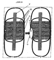
- FIG 1A illustrates the structure in the first aspect.
- the Indoskeltal Frame is constituted by the Central members and possibly the floorboard of the vehicle (3). Lateral rigidity is provided by the Safety Beam elements that may or may not be a part of the slide mechanism (4,5). Impact protection is provided by the side impact shock absorbers (4) which may include External Airbags (11) which in turn may require perforation shields (10). The normal situation is depicted in the illustration I and the situation under impact is illustrated in II.
- Figure 1B illustrates the Easy Ejector with Indo-Skeletal Crash Safety Beam with the positioning of passengers.
- Item 9 represents the Protector shield and the external airbags.
- Item 14 represents the Shock Absorbers and the Slide Beam (4) hand Easy Ejector slide (5) in the locked position.
- Item 6 is an auxiliary Safety Beam mounted on the Ejector slide and locked into position with the Ejector Slide in the operating position. In other embodiments this Safety Beam can be a part of the fixed structure with the outside end of the beam engaging the Shock Absorbers and the Protector Shield.
- the Passenger seat is represented by Item 7 and the Central body frame represented by Item 3.
- Figure 1C illustrates the effect of impact on Figure 1B.
- the impact side seat (7) decouples from the ejector slide (4,5), and the Ejector Slide and the Auxiliary Safety beam (6) along. with the Shock Absorber (14) and the Protector Shield (9) on the further side of the vehicle unlock and both the seats are free to eject to the extent necessary to avoid crushing injury.
- the bulk of the Impact is borne by the compressed shock absorbers (14) the Slide (4,5) and Safety Beam (6), and the main body elements of the vehicle Items 3.
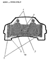
- Figure 2A illustrates the "Safety Zones" that the design of the vehicle will meet. These safety zones (15) will target the profiles of the passengers. Other regions will have minimal protection to reduce vehicle weight.
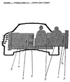
- Figure 2B illustrates an embodiment of the seats.
- Items 16 represent the mounting brackets for the safety harness.
- the mount on the internal side may be hinged to open upwards while the mount on the external side may be locked in the operating position. It may also be installed on the fixed members of the vehicle so that the seat slides in under the harness and locks in place.
- Item 17 is the safety harness that may be of a semi rigid material that provides support for the entire upper body in a head on collision.
- Features of the seat may include contoured armrests (18) and body cavity (19).
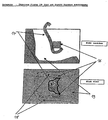
- Figure 3A is an isometric view of an embodiment.
- Figures 3 B&C illustrate the sectional elevation the structural design of this invention in its preferred embodiment.
- the Body of the vehicle Item 1 and Item 2 is shown along with an embodiment of the device in schematic section both in the mounting position and the operating position.
- the "B” figure illustrates the device in the extended position.
- the “C” figure illustrates the operating position.
- these figures illustrate the ejector mechanism that may be a slide structure Items 4 and 5 in Figures 3 B & C, on which is mounted the passenger seat - item 7 in figures 3 B & C.
- Item 3 represents the main structural member of the skeletal frame.
- Item 4 is the lower slide for the ejector seat - the Slide Beam
- Item 5 is the upper slide of the ejector seat - The Ejector Slide. In the operating position these slide together and the Safety Beam -
- the Safety Beam can be a fixed member of the Skeletal Frame that locks into the Shock Absorber and the Protector Shield in the operating position.
- Item 6 locks with the Skeletal Frame with the locking device - Items 13.
- the seat - Item 7 is contoured for comfort and will have all the movement and positioning capabilities of a conventional vehicle seat in the operating position. It is connected to the Ejector slide through impact decouplers items 8.
- decouplers may in some embodiments be designed as secondary slides that when decoupled under impact, guide the seats and passengers out of the vehicle.
- the Shock Absorbers -Item 14 are fixed to the Ejector Slide and the Safety Beam on one side and the Protector Shield -Item 9.
- the External Air Bags are located between the Protector Shield and the Perforation Shield - Item 10 and are activated with the velocity detectors - Item 12.
- the Indo Skeletal Structure is an innovation that pioneers a new paradigm in automobile and other passenger vehicle design using a safety driven "Indo-skeletal" (internal skeleton) frame rather than present day "exo-skeletal" or shell based bodies that are inherently weaker under compressive loads encountered in collisions. It is distinct from early period automobile design in that the skeletal structures are safety oriented rather than focussed on the mechanical functioning of the vehicle. It is notable that the Safety Endo-skeletal design captures the evolution in structural priorities in the more developed living organisms.
- the Easy Ejector aspect (second aspect) provides an ergonomically utilitarian, easy and comfortable approach to mount and dismount from motor vehicles.
- the passenger seats are ejected outside the body of the vehicle for ease of mounting and dismounting with slides or extension arms, and moved into the operating or travelling position when desired. Moreover in the event of a lateral collision it provides the mechanism to eject passengers if necessary to prevent crush injuries.
- the Easy Ejector is particularly suitable for automobiles and smaller passenger vehicles. Its utilitarian value in this regard is particularly notable for the elderly, the disabled, and infants.
- the two main aspects are related in that there are significant synergies in their combined embodiment.
- the use of the Easy Ejector paradigm along with the indo-Skeletal Structure utilizing many of the structural elements for both purposes, provide utilitarian access to the motor vehicle and reduces the risk of injury to drivers and passengers in side impact collisions (lateral collisions) in all types of motor vehicles. While motor vehicle movement can be controlled in the forward and backward directions there is little or no control of motor vehicle movement in the lateral direction. Therefore while sophisticated vehicle speed controls and other innovations may be designed to protect passengers in head on or tail end collisions, passengers are very vulnerable in lateral collisions. This device addresses this need while providing easy access to the vehicle for passengers.
- the First aspect provides a new paradigm for vehicle design structures - The Safety Indo-Skeletal structure or internal skeletal structure.
- the Internal structural members are designed principally for safety of the passengers, and together form a protective structure particularly for lateral impact.
- the design of the structure will transfer the impact in collisions directly through compressive members and compressive shock absorbers of the structure to the components of the vehicle with high mass, and thereby protect the passengers.
- the structure uses members that will be under compressive rather than under shear loads permitting the use of lighter material requirements to withstand the same forces as in conventional designs on impact.
- conventional shock absorbers and air bags will be used in conjunction with the rigid members in compression to absorb the energy of impact.
- the shock absorbers and air bags may be proactively fired (with strategically placed sensors) or reactive as in conventional designs. Overall this will provide greater safety for passengers for the same vehicle weight.
- the Safety Indo-Skeletal structure for passenger vehicle design identifies targeted "impact zones" (Please refer to Figure 2A) that could affect passengers and provides a path for transferring the energy of such encountered impact directly to the high mass components of the vehicle through compression bearing rigid and shock absorbing elements, thereby protecting the passengers from the impact and compressive loads of such collisions.
- Passengers while a part of the inertial mass of the vehicle are decoupled from the transfer of the energy to the remainder of the vehicle.
- the transfer of energy takes place through structural members under compressive load in the skeletal structure.
- the design will have shock absorbers placed at locations where impact affecting passengers is likely to occur. Shock absorbers in some embodiments may be proactive (with suitable lateral velocity and distance sensors) or reactive (as in conventional design).
- the design of the structure targets safety of passengers in lateral or side impact collisions.
- the structure has the following characteristics:
- the second aspect provides a new paradigm for access to motor vehicles.
- the customary approach for mounting and dismounting contemporary motor vehicles is by entering a door and then easing ones self into a seat that is fixed (such seats may allow limited forward and backward adjustments but no significant lateral movement) .
- This aspect The Easy Ejector, slides or extends the seat out of the vehicle allowing the passenger(s) to sit comfortably in the seat and then be moved into the travelling or operating position, automatically or with minimal manual effort.
- the reverse process is followed to dismount from the vehicle.
- the structure permits the design of passenger seats that provide support on all sides of the passenger (including the exit side). This is not available in contemporary motor vehicles. Moreover this facilitates provision of rigid protective sides to the seat that will protect the passenger in a collision.
- the door of the vehicle may or may not be a part of the integrated device or structure.
- the device includes Shock absorbers at the outer extreme of each Ejector Beam coupled with the rigid structure of the Easy Ejector Beam Slide (locked with the chassis when the vehicle is in motion).
- the outer face of the shock absorber Protector shield
- This Protector Shield may be hinged to exit the vehicle if desired without using the ejector mechanism.
- the seat is mounted on the Easy Ejector Beam Slide with mechanical decoupling in the event of impact. This slide also provides the Indo-Skeletal member that protects the passenger. This dual role reduces required mass of the vehicle to perform these functions.
- the function of the vehicle door will in most embodiments be reduced to a "Perforation Shield” ( as noted below), its cosmetic value in the design of the vehicle, and its weather protection attributes.
- Lateral velocity and distance detectors may be mounted on the Perforation shield (and the Safety shield) to detect possible side collisions to activate external airbags.
- airbags may be mounted between the safety shield and the Perforation shield.
- the Easy Ejector provides protection by withstanding compressive loads through the Ejector Slide, the Slide Beam and the Auxiliary Safety Beam, rather than provide protection through resistance to a shear load as in shell structures in conventional car bodies
- lightweight materials may be used as a substitute for the strength members in the vehicle design. The following is a detailed description of some of the components of this embodiment.
- the Slide Beam has the dual characteristics of providing a utilitarian approach for mounting and dismounting motor vehicles, and providing protection in side impact or lateral collisions because of its strength under compression.
- the Slide Beam supports the ejector Slide which has freedom in lateral motion.
- the slide provides the lateral movement for the seat at the time of mounting and dismounting from the vehicle. It may be used in conjunction with ball bearing or roller mechanisms. In addition in the locked position it provides the dual function of side impact protection. This protection is enhanced with an Auxiliary Safety Beam as noted earlier the Safety Beam may also be a fixed element of the Skeletal Structure that is locked to the shock absorbers and the protector shield in the operating position. which is mounted on the Ejector Slide possibly behind the passenger seat, In the operating position, it is locked to the frame as is the Slide
- the Easy ejector seat will have all the movement and cushioning features of conventional vehicle seats. However in addition it may be contoured to provide integrated lumbar and side support on both sides of the body - a feature that is not possible in conventional seats as free access on the door side is required in such designs. In conventional designs the door surface provides the only support on the external side surface which are usually limited to arm rests.
- the lower cost embodiments may have only the lower seat with the lumbar side supports ejecting, whereas more expensive embodiments may have the entire seat ejecting.
- the "Custom contoured seats" customized for each passenger may be created with surround inserts to cradle the entire lower body in the ejector seat. Similarly child seats may be designed to protect children (see below). Changes in this structure may be made.
- the seat will be mechanically decoupled from the Easy Ejector Slide for impact protection. While the decoupled seat will remain rigidly supported by the locked slide under normal operation conditions significant shocks - normally unsustainable by the human body -- will decouple the slide from the seat to allow the slide to convey the impact energy to the main structural members of the vehicle while allowing the seats independent movement that could result in ejection on the further side of the vehicle (away from the impact).
- the seat decouplers may be designed as secondary slides on the Ejector Slide.
- the easy Ejector may have conventional seat belts or a safety harness that locks over the lap after mounting. This can be manually locked in place with a hinged structure that locks over the lap or may be part of the fixed anchor of the Easy ejector such that the seat positions itself under and locks into the harness.
- the harness may be constructed of pliable but semi-rigid material (such as high strength nylon) to provide support in a head on collision.
- the door of the vehicle may be rear hinged and provide support for the slide.
- the clearance on the side of the vehicle for the Easy Ejector in the extended position will usually be in the range of about 20 inches to 30 inches. This could be substantially less than the clearance required for opening a conventional car door. This is particularly useful for parking in areas with limited clearance.
- the shock absorber provides the energy absorbing capability between the inertial mass of the vehicle and the impacting body in a side collision. It may be mounted on the ejector slide with the external face locked to or fixed to he Protector shield (below). In addition in the operating position the shock absorber will be locked to the sliding beam.
- Figure 3 B & C Items 13 Notably, the internal end of the ejector slide will be locked to the vehicle frame during operation.
- the impact shield that is directly connected to the shock absorber. In most embodiments it will cover much of the side profile of the passenger.
- the face of the Protector Shield may be hinged out to allow mounting the seat without extending or sliding out Easy Ejector for designs that use conventional doors.
- This provides perforation protection from sharp objects in a collision both for the passenger and the external air bag (below). It would in most embodiments be the vehicle door or the outer skin thereof.
- some embodiments may have several functions for the door.
- the door may have double skins particularly for the Perforation shield function and the Slide Support Function.
- the Door may be designed to provide support for the Easy Ejector Slide particularly for larger vehicles with multiple seats on each Easy Ejector Slide.
- a rear hinge will avoid obstruction to the passenger at the time of mounting and dismounting from the vehicle.
- the door may function as Mount for Side impact velocity detectors. This safety feature provides early warning to deploy the side impact external air bags.
- the door will have lateral velocity and distance detectors (possibly infrared) to detect lateral velocity at close proximity to fire external airbags from the Protector Shield to protect the vehicle and the passengers.
- the vehicle while in operation should have the Safety Beam and the Ejector Slide retracted and locked.
- the ignition lock may be used in some embodiments to ensure this practice.
- the easy ejector Protector Shield may have a fixed or retractable "Safety Cage" structure that surrounds the passenger in a vertical plane, thereby protecting the passenger in a roll over situation.
- the Safety Cage may be simply a retractable roll bar.
- Some embodiments may have internal side impact airbags that "unfurl" upwards on impact thereby protecting the passenger's body.
- the Safety harness may also have an attachment for providing greater support for infants and small children.
- This embodiment benefits from synergies of using the two aspects together. Numerous variations on this embodiment are possible. Current passenger motor vehicles use hinged doors for entry and exit for passengers and separate laterally fixed seats (no side to side movement) within the motor vehicle passenger compartment for the passengers while travelling in the vehicle. Moreover such motor vehicles do not usually have design focussed on lateral impact safety devices besides the impact protection of the side door and possibly internal side impact air bags.
- This embodiment - the Ejector and Crash Safety Beam -- provides the dual role of an Easy Ejector device with the Safety Indo-Skeletal Structure that provides utilitarian access to passenger vehicles and provides Safety characteristics using the Indo-Skeletal structure as noted herein.
- the elements of this embodiment are as follows:
- the Slide Beam - Item 4 in Figures 3 serves the dual role of both a structural member that provides compressive strength and also the support for the Easy Ejector Slide.
- the Easy Ejector Slide - Item 5 in Figures 3 B and C slides over the Slide beam and in the operating position is locked to the main body of the vehicle Item 3 in Figures 3 B and C. In this position it provides structural strength under compression as well.
- the Easy Ejector Slide supports the seat (Item 7 in Figures 3 B and C) through mounts (Items 8 in Figures 3) that decouple at the time of impact.
- a secondary sliding design of the decoupler facilitates sliding of the seat over the Ejector Slide.
- the Slide Beam/Easy Ejector Slide combination may have multiple elements with multiple sets of slides and/or roller mounts. In some embodiments the slide Beam/Easy Ejector Slide combination may have several elements that collapse together in the Operating position.
- the Easy Ejector Seat for the passenger - Item 7 in Figures 3 B and C is firmly mounted through decouplers (Items 8 in Figure 3 B and C) to the Easy Ejector Slide. At the time of impact the decouplers will disengage the seat to permit limited lateral movement or sliding on the Easy ejector Slide (away from the impact point).
- the Easy Ejector Seat may be designed to have multi directional movement and position adjustments for comfort as in conventional motor vehicle seats with mechanisms mounted on the decouplers.
- the Easy Ejector seat In some embodiments may be constructed to have both sides of the seat reinforced to prevent crushing injuries to passengers in collisions.
- Some embodiments may have the "Pop-Out Ejector" feature that allows, under impact on one side, the unlocking of the Easy Ejector Slide on the other side and the limited movement of the seats on the decouplers, to allow the seats to slide out to a limited extent, thereby preventing the entrapment of passengers in a collision and minimizing the maximum acceleration under impact that the passengers encounter. Moreover this feature will reduce the likelihood of the body of the vehicle under impact crushing the passengers.
- Some embodiments may have the Safety Beam - Item 6 in Figures 3 B and C. a structural member that provides compressive strength. It is mounted on the Easy Ejector Slide and in the operating position locks into the frame of the vehicle (Item 3 in Figures 3 B and C) .
- the shock absorber (see below) is mounted at its outside end.
- Some embodiments may have the Shock Absorber - Item 14 in Figures 3 B and C, which is mounted on the end of the Easy Slide Beam and the Safety Beam, and may support a Protector Shield.
- Some embodiments may have a Protector Shield - Item 9 in Figures 3 B and C, provides the cover for much of the side profile of the passenger to provide impact protection at different possible contact points on impact.
- Some embodiments may have the External Airbag - Item 11 in Figures 3 B and C, that may be fired proactively with velocity/ distance sensors on the side of the vehicle. (Items 12 in Figure 3 B and C) These airbags will reduce the maximum acceleration of the passengers under impact.
- some embodiments may have the Perforation shield which is a thin skin that is on the outside of the vehicle protecting the external airbag from perforation and providing the cosmetic functions of the outside of the vehicle. Velocity/distance sensors may be mounted on these perforation shields.
- Some embodiments may have the Skeletal Locks - Items 13 in Figures 3 B and C, provide the locking mechanism for the Easy ejector Slide, the Safety Beam and the Slide Beam.
- Some embodiments may have extensions of the protector Shield that extend over the passenger so that in the operating position these extensions engage a beam across the vehicle to prove further strength in a side impact.
- a unique characteristic of the Easy Ejector Structure is that there can be ergonomic passenger seat support on both sides of the lower body as well as behind and below as in conventional seats.
- the Multi-element contour seat may be customized to fit the lower body. (either with manual inserts or with computer controlled elements that can be preset for each passenger). In some embodiments such muli-element contour seats may provide lateral support in addition to what conventional passenger seats provide. This is of particular value in reducing driver fatigue on winding roads and rough terrain.
- a Gravity Slide Drive may be used as an alternative to an Electric power slide drive for the Easy Ejector. Either of these embodiments may be preferred depending on principally cost and weight factors.
- the Gravity Slide Drive operates as follows:
- the slide has two inclinations - the "operating inclination” and the "loading inclination”.
- the operating inclination has a slight incline upwards from the center of the vehicle. This is the incline of the slide that will be locked into position during the operation of the vehicle. The weight of the passenger will draw the passenger towards the operating position in the operating inclination despite the resistance of the "loader spring” to be defined below.
- the inclination refers to the slide mechanism that in some embodiments will be rollers. It does not refer to the inclination of the Slide Beam or the Easy Ejector Slide. These would normally be horizontal in the operating position to maximize the impact resistance.
- the Loading inclination has a slight downward inclination so that the passenger's weight will slide out the seat and the slide to the extended position.
- the Slide From the operating position when the Inside-Open button is operated, the Slide moves and is locked to the Loading inclination and the seat slides out permitting the passenger to dismount.
- the release of the weight of the passenger from the slide raises and locks the Slide in the Operating Inclination when the new passenger sits on the seat the body weight of this passenger slides the seat and the slide to the Operating Position. If there is no new passenger, the empty seat may be allowed to slide under gravity to the operating position. A spring mechanism will retard this motion so that while it is easy to slide in it is not automatic.
- the passenger will operate the Outside-Open button. This will allow the slide to be drawn out assisted by the Spring mechanism.
- the Slide will be in the Operating Inclination during this movement, however the spring action will ease the movement of the slide to the extended position as there is no weight of a passenger in the seat to counter. Note that the Outside-Open button does not release the catch for the depression of the slide to the Mounting Inclination whereas the Inside-Open button does.
- the Easy Ejector provides a structure that allows utilitarian and easy mounting and dismounting from passenger vehicles. Moreover, it provides an ejector mechanism that may be activated in the event of lateral collisions. In such situations this structure could prevent crushing injury and avoid unsustainable levels of acceleration of the human body.
- the Easy Ejector provides a structure that mounts one or more passenger seats on a lateral slide, extension or rotating mechanism that permits passengers to move their seats either manually or with automation from the operating position for driving or travelling position for passengers to the ejected position that is clear of but adjoining the body of the vehicle permitting easy mounting/dismounting by moving from the seated position to the standing position or vice versa.
- the passenger thereby mounts the vehicle by standing beside the vehicle and lowers him/her self into the seat, then retracts the Easy Ejector and is then in the driving or travelling position.
- Ejects the Easy Ejector and from a sitting position simply stands up beside the vehicle on the ground.
- the Easy Ejector seats may be decoupled to allow the passenger seats to slide away from the collision, allowing the main thrust of the impact to be borne by the vehicle body and other components of the vehicle.
- Preferred feature 1 CRUSH RESISTANT SEAT FRAME
- the Easy Ejector seat is preferably constructed to have both sides of the seat reinforced to prevent crushing injuries to passengers in collisions. Conventional passenger seats do not have this facility as the entry side of the seat needs to be open for access.
- the "Pop-out Ejector” feature preferably allows under impact on one side, the unlocking of the Easy Ejector Slide on the other side of the vehicle and the decoupling of the secondary slide/decoupler on the impact side to allow limited movement of the seats that allows them to slide out adequately to prevent the entrapment of passengers in a collision and minimizing the maximum acceleration under impact that the passengers encounter. Moreover this feature will' reduce the likelihood of the body of the vehicle under impact, crushing the passengers.
- the preferably provided Safety Beam - Item 6 in Figures 3 B and C is a structural member that provides compressive strength. It is either mounted on the Easy Ejector Slide and in the operating position locks into the frame of the vehicle (Item 3 in Figures 3 B and C) with the shock absorber and Protector Shield fixed to it on the outside end, or is mounted on the fixed Skeletal Frame and is locked into the shock absorbers and the Protector Shield in the operating position.
- the Safety Beam may be mounted behind the passenger seat.
- Preferred feature 4 THE SHOCK ABSORBER
- the Shock Absorber - Item 14 in Figures 3 B and C is preferably mounted on the end of the Ejector Slide and the Safety Beam, and may support a Protector Shield.
- a Protector Shield - Item 9 in Figures 3 B and C prefearbly provides the cover for much of the side profile of the passenger to provide impact protection at different possible contact points on impact.
- the said Protector Shield may in some embodiments be hinged to allow passengers to dismount without Ejecting the Easy Ejector mechanism.
- the preferably provided External Airbag - Item 11 in Figures 3 B,C may be fired on/before impact. These airbags will reduce the maximum acceleration of the passengers (and the vehicle) under impact.
- Preferred feature 1 PROACTIVE LATERAL IMPACT SENSORS
- Proactive velocity and distance sensors are preferably mounted on the side of the vehicle (Items 12 in Figure 3B,C), to sense impending impact to trigger the airbags in Claim 8.
- Preferred feature 8 THE PERFORATION SHIELD
- the preferably provided Perforation shield is a thin skin that is on the outside of the vehicle protecting the external airbag from perforation and providing the cosmetic functions of the outside of the vehicle. Velocity/distance sensors may be mounted on these perforation shields.
- Preferred feature 9 THE SKELETAL LOCK
- the Skeletal Locks - Items 13 in Figures 3 B and C preferably provide the locking mechanism for the Ejector Slide, the Safety Beam and the Slide Beam and the other fixed members of the vehicle body.
- Some embodiments may use an "ignition lock" to avoid release of the skeletal lock while the vehicle is operational. Such a lock can be conditionally disabled to permit the implementation of preferred feature 4 if desired.
- Preferred feature 10 SAFETY CAGE
- Extensions of the protector Shield preferably extend over the passenger so that in the operating position these extensions engage a beam across the top of the vehicle to provide further strength in a side impact.
- Preferred feature 11 MULTI-ELEMENT CONTOUR SEAT
- a multi- element contour seat is preferably provided.
- a unique feature of the Easy Ejector structure is that there can be ergonomic passenger seat support on both sides of the lower body as well as behind and below as in conventional seats.
- the Multi-element contour seat may be customized to fit the lower body (either with manual inserts or with computer controlled elements that can be preset for each passenger) .
- such muli-element contour seats may provide lateral support in addition to what conventional passenger seats provide. This is of particular value in reducing driver fatigue on winding roads and rough terrain.
- Preferred feature 12 SEMI RIGID SAFETY HARNESS
- the Safety harness may be designed to lock over the lap after the passenger mounts. This can be manually locked in place with a hinged structure that locks over the lap or may be part of the fixed anchor of the Easy ejector such that the seat positions itself under and locks into the harness.
- the harness may in some embodiments be constructed of pliable but semi-rigid material (such as high strength nylon) to provide support in a head on collision.
- a unique feature of this harness relative to conventional seat belts is that, the Harness may be installed such that it does not touch the passenger in normal operation, but provides exceptional protection under impact.
- FIG. 2 B shows how the Harness covers the front of the body with a hinged mount on the interior side of the seat and a locking device on the exterior side of the seat. Another unique feature of this harness is that it may extend over the upper body, obviating the need for a front collision airbag for the protection of the passenger.
- Preferred feature 13 SEAT INSERTS FOR CUSTOMIZATION/CHILD SEAT
- Inserts for customizing the seats for individual passengers may be provided. Such customization can be for children.
- Preferred feature 14 DOOR SUPPORT FOR EJECTOR SLIDE/SLIDE BEAM
- a rear hinged door that provides support for the Ejector Slide and, in some embodiments an extending section of the Slide Beam is preferably provided. This will be particularly useful for Ejector Slides that have multiple seats in larger vehicles.
- Preferred feature 15 GRAVITY SLIDE DRIVE (MANUAL SLIDE)
- the Gravity Slide Drive may preferably be used for manual operation of the Ejector with Crash Safety Beam. Several variations of the following are possible.
- the Gravity Slide Drive operates as follows: The slide has two inclinations the "operating inclination” and the “loading inclination”.
- the operating inclination has a slight incline upwards from the center of the vehicle. This is the incline of the slide that will be locked into position during the operation of the vehicle. The weight of the passenger will draw the passenger towards the operating position in the operating inclination despite the resistance of the "loader spring” to be defined below.
- the inclination refers to the slide mechanism that in some embodiments will be rollers. It does not refer to the inclination of the Slide Beam or the Easy Ejector Slide. These would normally be horizontal in the operating position to maximize the impact resistance.
- the Loading inclination has a slight downward inclination so that the passenger's weight will slide out the seat and the slide to the extended position.
- the passenger will operate the Outside-Open button. This will allow the slide to be drawn out assisted by the Spring mechanism.
- the Slide will be in the Operating Inclination during this movement, however the spring action will ease the movement of the slide to the extended position as there is no weight of a passenger in the seat to counter. Note that the Outside-open button does not release the catch for the depression of the slide to the Mounting Inclination whereas the' Inside-Open button does.
Landscapes
- Engineering & Computer Science (AREA)
- Transportation (AREA)
- Mechanical Engineering (AREA)
- Aviation & Aerospace Engineering (AREA)
- Chemical & Material Sciences (AREA)
- Combustion & Propulsion (AREA)
- Seats For Vehicles (AREA)
- Air Bags (AREA)
- Vibration Dampers (AREA)
- Body Structure For Vehicles (AREA)
- Window Of Vehicle (AREA)
- Extrusion Moulding Of Plastics Or The Like (AREA)
- Building Environments (AREA)
Priority Applications (8)
| Application Number | Priority Date | Filing Date | Title |
|---|---|---|---|
| EP20000203896 EP1099607B1 (en) | 1998-09-17 | 2000-11-07 | Easy ejector with skeletal crash safety beam |
| US09/779,592 US6742833B2 (en) | 1997-09-24 | 2001-02-09 | Easy ejector seat with skeletal crash safety beam |
| US09/779,593 US6715816B2 (en) | 1997-09-24 | 2001-02-09 | Easy ejector seat with skeletal crash safety beam |
| US09/779,591 US6609754B2 (en) | 1997-09-24 | 2001-02-09 | Easy ejector seat with skeletal crash safety beam |
| US09/779,594 US7255389B2 (en) | 1997-09-24 | 2001-02-09 | Easy ejector seat with skeletal crash safety beam |
| US10/109,674 US7159923B2 (en) | 1998-09-17 | 2002-04-01 | Easy ejector seat with skeletal crash safety beam |
| US10/681,304 US7175221B2 (en) | 1998-09-17 | 2003-10-09 | Easy ejector seat with skeletal crash safety beam |
| US11/185,784 US8020658B2 (en) | 1998-09-17 | 2005-07-21 | Easy ejector seat with skeletal crash safety beam |
Applications Claiming Priority (3)
| Application Number | Priority Date | Filing Date | Title |
|---|---|---|---|
| US08/936,626 US6059354A (en) | 1997-09-24 | 1997-09-24 | Easy ejector seat with skeletal crash safety beam |
| PCT/US1998/019260 WO1999015379A1 (en) | 1997-09-24 | 1998-09-17 | Easy ejector seat and indo-skeletal crash safety beam |
| US936626 | 2004-09-08 |
Publications (3)
| Publication Number | Publication Date |
|---|---|
| EP1021320A1 EP1021320A1 (en) | 2000-07-26 |
| EP1021320A4 EP1021320A4 (en) | 2000-12-27 |
| EP1021320B1 true EP1021320B1 (en) | 2005-11-09 |
Family
ID=25468893
Family Applications (1)
| Application Number | Title | Priority Date | Filing Date |
|---|---|---|---|
| EP98948260A Expired - Lifetime EP1021320B1 (en) | 1997-09-24 | 1998-09-17 | Easy ejector seat and indo-skeletal crash safety beam |
Country Status (9)
| Country | Link |
|---|---|
| US (3) | US6059354A (enExample) |
| EP (1) | EP1021320B1 (enExample) |
| JP (1) | JP4144661B2 (enExample) |
| KR (1) | KR20010015619A (enExample) |
| AT (1) | ATE309121T1 (enExample) |
| AU (1) | AU772852B2 (enExample) |
| DE (1) | DE69832295T2 (enExample) |
| ES (1) | ES2252860T3 (enExample) |
| WO (1) | WO1999015379A1 (enExample) |
Cited By (1)
| Publication number | Priority date | Publication date | Assignee | Title |
|---|---|---|---|---|
| US9211820B2 (en) | 2012-11-01 | 2015-12-15 | Graco Children's Products Inc. | Child safety seat with side impact energy redirection |
Families Citing this family (19)
| Publication number | Priority date | Publication date | Assignee | Title |
|---|---|---|---|---|
| US9902298B1 (en) | 1999-09-24 | 2018-02-27 | Arjuna Indraeswaran Rajasingham | Vehicle occupant support |
| US11046215B1 (en) | 1999-09-24 | 2021-06-29 | Arjuna Indraeswaran Rajasingham | Vehicle occupant support |
| US9669739B1 (en) | 1999-11-08 | 2017-06-06 | Arjuna Indraeswaran Rajasingham | Vehicle occupant support |
| EP1325836B1 (en) * | 2001-04-02 | 2007-07-18 | Arjuna Indraeswaren Dr. Rajasingham | Easy ejector seat with skeletal crash safety beam |
| DE10143881B4 (de) * | 2001-09-06 | 2005-06-02 | Lortz, Wolfgang, Prof. Dr.-Ing. | Verformungselement und Sitz |
| DE10150719B4 (de) | 2001-10-13 | 2004-11-11 | Daimlerchrysler Ag | Fahrzeugsitz und Verfahren zur Ansteuerung desselben |
| US11364822B1 (en) * | 2005-12-19 | 2022-06-21 | Arjuna Indraeswaran Rajasingham | Vehicle occupant support |
| JP4380565B2 (ja) * | 2005-03-10 | 2009-12-09 | トヨタ自動車株式会社 | 側突荷重伝達構造 |
| DE102006044121A1 (de) * | 2006-09-15 | 2008-03-27 | Jens Schauring | Sicherheitsvorrichtung für Fahrzeuge |
| DE102008017199A1 (de) * | 2008-04-04 | 2009-10-08 | GM Global Technology Operations, Inc., Detroit | Kindersitzsystem |
| JP5859312B2 (ja) | 2009-01-28 | 2016-02-10 | ラジャーシンガム、アージューナ・イドレイスワラン | 車両乗客支持体 |
| CN103370258B (zh) * | 2011-02-15 | 2016-05-18 | 丰田自动车株式会社 | 车辆下部结构 |
| US8573640B2 (en) * | 2012-03-13 | 2013-11-05 | Ford Global Technologies, Llc | Side collision occupant protection system |
| DE102012204856A1 (de) * | 2012-03-27 | 2013-10-02 | Robert Bosch Gmbh | Massekopplungsanordnung für ein Fahrzeug |
| DE102013206508A1 (de) * | 2013-04-12 | 2014-10-16 | Robert Bosch Gmbh | Steuervorrichtung für eine Objektankopplungsvorrichtung eines Fahrzeugs, Objektankopplungsvorrichtung für ein Fahrzeug und Verfahren zum Dämpfen eines Aufpralls eines trägheitsbeschleunigten Objekts |
| US9783310B2 (en) | 2013-08-26 | 2017-10-10 | Ami Industries, Inc | Ejection seat pan lifter |
| DE102016219105B4 (de) | 2016-09-30 | 2024-11-07 | Brose Fahrzeugteile SE & Co. Kommanditgesellschaft, Coburg | Verstellvorrichtung mit Spindelantrieb für ein Sitzelement eines Fahrzeugsitzes |
| US10604104B2 (en) * | 2018-03-27 | 2020-03-31 | GM Global Technology Operations LLC | Front and rear deployable containment system |
| US11845558B2 (en) * | 2021-08-19 | 2023-12-19 | Recaro Aircraft Seating Gmbh & Co. Kg | Aircraft passenger seat device with a connection unit comprising an impact safety device |
Family Cites Families (51)
| Publication number | Priority date | Publication date | Assignee | Title |
|---|---|---|---|---|
| DE741063C (de) * | 1935-10-22 | 1943-11-03 | Friedrich Maier Dipl Ing | Kraftfahrzeug mit selbsttragendem Wagenkasten |
| US2710222A (en) * | 1949-01-22 | 1955-06-07 | Barenyi Bela | Reinforced floor plate for body of sectional automobile |
| US2587679A (en) * | 1950-04-28 | 1952-03-04 | Dale S Atkinson | Adjustable seat for automobiles |
| US2758872A (en) * | 1953-07-09 | 1956-08-14 | Solomon Benjamin | Laterally-movable vehicle seat through doorway |
| US2753947A (en) * | 1954-08-31 | 1956-07-10 | Gen Motors Corp | Forward mounted truck cab with a movable seat |
| US2777531A (en) * | 1954-10-22 | 1957-01-15 | Norman R Erickson | Emergency crash seat |
| US2873122A (en) * | 1955-10-17 | 1959-02-10 | Renault | Safety seat for motor vehicles |
| US3071407A (en) * | 1960-07-11 | 1963-01-01 | Frank C Sloan | Transversely movable passenger seat for automobiles, taxicabs and the like |
| US3129017A (en) * | 1961-03-22 | 1964-04-14 | Graham Phillip | Vehicle occupant safety barrier |
| US3545789A (en) * | 1968-03-04 | 1970-12-08 | Phillip Graham | Vehicle occupant safety barrier |
| US3735398A (en) * | 1971-05-20 | 1973-05-22 | Sperry Rand Corp | Base band short range pre-collision sensor for actuation of vehicle safety apparatus |
| US3713695A (en) * | 1971-08-27 | 1973-01-30 | Wimmersperg H Von | Safety device for restraining passengers |
| US4082350A (en) * | 1971-09-22 | 1978-04-04 | Daimler-Benz Aktiengesellschaft | Shell-shaped children's seat for vehicles |
| US3762505A (en) * | 1971-12-01 | 1973-10-02 | S Morse | Device for reducing severity of impact forces |
| US3822076A (en) * | 1972-01-24 | 1974-07-02 | Peugeot & Renault | Fluid shock absorbing buffer |
| GB1460782A (en) * | 1973-04-13 | 1977-01-06 | Satzinger Roland | Vehicle seat assembly |
| DE2416313C3 (de) * | 1974-04-04 | 1978-11-23 | Roland 8731 Euerdorf Satzinger | Sicherheitseinrichtung für die Insassen von Fahrzeugen, insbesondere Kraftfahrzeugen |
| US3922030A (en) * | 1974-06-24 | 1975-11-25 | Caterpillar Tractor Co | Protective seat |
| US3944277A (en) * | 1974-11-01 | 1976-03-16 | Cyphert Lloyd W | Sidewardly movable vehicle seat with enclosure |
| US3981520A (en) * | 1975-05-05 | 1976-09-21 | Liberty Mutual Insurance Company | Protective enclosure for passengers of transport devices |
| JPS6344266Y2 (enExample) * | 1981-04-20 | 1988-11-17 | ||
| US4580842A (en) * | 1983-08-19 | 1986-04-08 | Joseph Segal | Restraining means for a child car seat |
| US4533172A (en) * | 1984-02-06 | 1985-08-06 | Oliver Gary R | Disconnectable automotive vehicle frame |
| US4664443A (en) * | 1985-11-08 | 1987-05-12 | Casale Rudy J | Automobile convertible seat |
| US4671563A (en) * | 1986-08-04 | 1987-06-09 | General Motors Corporation | Small lightweight automotive vehicle having swingable rear seating module means |
| US4815777A (en) * | 1987-08-10 | 1989-03-28 | Campbell Kenneth J | Selectively movable protective molding and methods of constructing and utilizing same |
| JPH0195948A (ja) * | 1987-10-09 | 1989-04-14 | Honda Motor Co Ltd | 移動シート付自動車 |
| WO1989003328A1 (en) * | 1987-10-15 | 1989-04-20 | Lee, Sang, Man | Shock absorber for a car |
| DE3928869B4 (de) * | 1988-09-07 | 2004-08-05 | Volkswagen Ag | Sicherheitseinrichtung für ein Kraftfahrzeug |
| DE3915173A1 (de) * | 1989-05-10 | 1989-11-30 | Ekkehard Pott | Sicherheits-kindersitz mit passivem rueckhaltesystem |
| US5131703A (en) * | 1991-09-27 | 1992-07-21 | Stirling Leroy D | Protective collision guard for vehicle |
| JPH05114621A (ja) * | 1991-10-22 | 1993-05-07 | Toshiba Corp | 半導体樹脂封止装置 |
| US5213300A (en) * | 1991-12-17 | 1993-05-25 | Itt Corporation | Extruded automotive seat track |
| DE4212091A1 (de) * | 1992-04-10 | 1993-10-14 | Martin Beisner | Seitenverschiebbare Personensitze zur Verminderung der Verletzungsgefahr in Personenkraftwagen bei Seitencrashs |
| US5531470A (en) * | 1992-07-13 | 1996-07-02 | Joalto Design, Inc. | Side air bag incorporated in vehicle outer armrest |
| DE4302505C2 (de) * | 1993-01-29 | 1998-07-30 | Daimler Benz Ag | Fahrgastzelle mit einer im Bereich der Sitze angeordneten Querversteifung |
| US5464246A (en) * | 1993-02-19 | 1995-11-07 | Simula Inc. | Inflatable tubular cushions for crash protection of seated automobile occupants |
| DE4326270C2 (de) * | 1993-08-05 | 2003-01-30 | Daimler Chrysler Ag | Kraftfahrzeug mit einer steifen Bodenstruktur |
| US5474353A (en) * | 1993-12-01 | 1995-12-12 | Hoover Universal, Inc. | Pivoting seat cushion arrangement for vehicle seat assemblies |
| JP3993253B2 (ja) * | 1994-05-23 | 2007-10-17 | オートモーティブ・テクノロジーズ・インターナショナル,インク. | 予測センサを有する側部衝撃用エアバッグシステム |
| JP3335781B2 (ja) * | 1994-08-31 | 2002-10-21 | 富士重工業株式会社 | 車両のセンタピラー部全周閉断面構造 |
| US5476309A (en) * | 1994-11-29 | 1995-12-19 | Chen; K. C. | Safety harness for a vehicle seat |
| US5660428A (en) * | 1995-01-11 | 1997-08-26 | Xcorp, Inc. | Recyclable, low-cost, collision-resistant automobile chassis and body |
| GB9508646D0 (en) * | 1995-04-28 | 1995-06-14 | Ashley Adrian L | Lisa |
| FR2735096B1 (fr) * | 1995-06-09 | 1997-08-29 | Aerospatiale | Siege orientable de securite pour un vehicule tel qu'un aeronef. |
| US5810427A (en) * | 1996-03-18 | 1998-09-22 | Hartmann; Albrecht | Motor vehicle |
| JP3358450B2 (ja) * | 1996-07-09 | 2002-12-16 | 三菱自動車工業株式会社 | 自動車用座席 |
| US5725265A (en) * | 1997-01-16 | 1998-03-10 | Baber; Jeff | Air bag system for vehicle bumpers |
| US5716094A (en) * | 1997-03-06 | 1998-02-10 | General Motors Corporation | Vehicle seat with pusher block |
| US5947543A (en) * | 1997-04-03 | 1999-09-07 | Hubbard; Leo James | Vehicle safety system |
| JP4031819B2 (ja) * | 1998-09-07 | 2008-01-09 | 本田技研工業株式会社 | 小型4輪車両 |
-
1997
- 1997-09-24 US US08/936,626 patent/US6059354A/en not_active Expired - Fee Related
-
1998
- 1998-09-17 AT AT98948260T patent/ATE309121T1/de not_active IP Right Cessation
- 1998-09-17 KR KR1020007003153A patent/KR20010015619A/ko not_active Withdrawn
- 1998-09-17 WO PCT/US1998/019260 patent/WO1999015379A1/en not_active Ceased
- 1998-09-17 ES ES98948260T patent/ES2252860T3/es not_active Expired - Lifetime
- 1998-09-17 EP EP98948260A patent/EP1021320B1/en not_active Expired - Lifetime
- 1998-09-17 AU AU94871/98A patent/AU772852B2/en not_active Ceased
- 1998-09-17 DE DE69832295T patent/DE69832295T2/de not_active Expired - Fee Related
- 1998-09-17 JP JP2000512716A patent/JP4144661B2/ja not_active Expired - Fee Related
-
1999
- 1999-09-24 US US09/404,475 patent/US6547315B1/en not_active Expired - Fee Related
- 1999-11-08 US US09/435,830 patent/US6609749B1/en not_active Expired - Fee Related
Cited By (1)
| Publication number | Priority date | Publication date | Assignee | Title |
|---|---|---|---|---|
| US9211820B2 (en) | 2012-11-01 | 2015-12-15 | Graco Children's Products Inc. | Child safety seat with side impact energy redirection |
Also Published As
| Publication number | Publication date |
|---|---|
| WO1999015379A1 (en) | 1999-04-01 |
| AU772852B2 (en) | 2004-05-06 |
| AU9487198A (en) | 1999-04-12 |
| US6059354A (en) | 2000-05-09 |
| ATE309121T1 (de) | 2005-11-15 |
| US6547315B1 (en) | 2003-04-15 |
| DE69832295T2 (de) | 2007-02-15 |
| JP4144661B2 (ja) | 2008-09-03 |
| EP1021320A1 (en) | 2000-07-26 |
| JP2001517577A (ja) | 2001-10-09 |
| ES2252860T3 (es) | 2006-05-16 |
| DE69832295D1 (de) | 2005-12-15 |
| US6609749B1 (en) | 2003-08-26 |
| KR20010015619A (ko) | 2001-02-26 |
| EP1021320A4 (en) | 2000-12-27 |
Similar Documents
| Publication | Publication Date | Title |
|---|---|---|
| EP1021320B1 (en) | Easy ejector seat and indo-skeletal crash safety beam | |
| US6715816B2 (en) | Easy ejector seat with skeletal crash safety beam | |
| US8136835B2 (en) | Easy ejector seat with skeletal crash safety beam | |
| US8944492B2 (en) | Vehicle frame | |
| US10780857B1 (en) | Vehicle occupant support | |
| US20010026079A1 (en) | Vehicle embodying a system for protection in case of impact | |
| JPH09109924A (ja) | 自動車車体構造 | |
| US9669739B1 (en) | Vehicle occupant support | |
| US8138908B2 (en) | Easy ejector seat with skeletal crash safety beam | |
| US11091070B2 (en) | Suspension system for vehicle seat | |
| US7156416B2 (en) | Easy ejector seat with skeletal crash safety beam | |
| EP1099607B1 (en) | Easy ejector with skeletal crash safety beam | |
| US11046215B1 (en) | Vehicle occupant support | |
| EP1325836A2 (en) | Easy ejector seat with skeletal crash safety beam | |
| US9902298B1 (en) | Vehicle occupant support | |
| CA2151566A1 (en) | Passive restraint system |
Legal Events
| Date | Code | Title | Description |
|---|---|---|---|
| PUAI | Public reference made under article 153(3) epc to a published international application that has entered the european phase |
Free format text: ORIGINAL CODE: 0009012 |
|
| 17P | Request for examination filed |
Effective date: 20000413 |
|
| AK | Designated contracting states |
Kind code of ref document: A1 Designated state(s): AT BE CH CY DE DK ES FI FR GB GR IE IT LI LU MC NL PT SE |
|
| PUAF | Information related to the publication of a search report (a3 document) modified or deleted |
Free format text: ORIGINAL CODE: 0009199SEPU |
|
| D17D | Deferred search report published (deleted) | ||
| RIC1 | Information provided on ipc code assigned before grant |
Free format text: 7B 60R 27/00 A, 7B 60R 19/20 B, 7B 60N 2/06 B, 7B 60N 2/42 B, 7B 62D 21/15 B, 7B 62D 25/20 B |
|
| A4 | Supplementary search report drawn up and despatched | ||
| AK | Designated contracting states |
Kind code of ref document: A4 Designated state(s): AT BE CH CY DE DK ES FI FR GB GR IE IT LI LU MC NL PT SE |
|
| RA4 | Supplementary search report drawn up and despatched (corrected) |
Effective date: 20001030 |
|
| 17Q | First examination report despatched |
Effective date: 20020726 |
|
| RAP1 | Party data changed (applicant data changed or rights of an application transferred) |
Owner name: RAJASINGHAM, ARJUNA INDRAESWAREN, DR. |
|
| RIN1 | Information on inventor provided before grant (corrected) |
Inventor name: RAJASINGHAM, ARJUNA INDRAESWAREN, DR. |
|
| GRAP | Despatch of communication of intention to grant a patent |
Free format text: ORIGINAL CODE: EPIDOSNIGR1 |
|
| GRAS | Grant fee paid |
Free format text: ORIGINAL CODE: EPIDOSNIGR3 |
|
| GRAA | (expected) grant |
Free format text: ORIGINAL CODE: 0009210 |
|
| AK | Designated contracting states |
Kind code of ref document: B1 Designated state(s): AT BE CH CY DE DK ES FI FR GB GR IE IT LI LU MC NL PT SE |
|
| PG25 | Lapsed in a contracting state [announced via postgrant information from national office to epo] |
Ref country code: NL Free format text: LAPSE BECAUSE OF FAILURE TO SUBMIT A TRANSLATION OF THE DESCRIPTION OR TO PAY THE FEE WITHIN THE PRESCRIBED TIME-LIMIT Effective date: 20051109 Ref country code: FI Free format text: LAPSE BECAUSE OF FAILURE TO SUBMIT A TRANSLATION OF THE DESCRIPTION OR TO PAY THE FEE WITHIN THE PRESCRIBED TIME-LIMIT Effective date: 20051109 Ref country code: AT Free format text: LAPSE BECAUSE OF FAILURE TO SUBMIT A TRANSLATION OF THE DESCRIPTION OR TO PAY THE FEE WITHIN THE PRESCRIBED TIME-LIMIT Effective date: 20051109 |
|
| REG | Reference to a national code |
Ref country code: GB Ref legal event code: FG4D |
|
| REG | Reference to a national code |
Ref country code: CH Ref legal event code: EP |
|
| REG | Reference to a national code |
Ref country code: IE Ref legal event code: FG4D |
|
| REF | Corresponds to: |
Ref document number: 69832295 Country of ref document: DE Date of ref document: 20051215 Kind code of ref document: P |
|
| PG25 | Lapsed in a contracting state [announced via postgrant information from national office to epo] |
Ref country code: GR Free format text: LAPSE BECAUSE OF FAILURE TO SUBMIT A TRANSLATION OF THE DESCRIPTION OR TO PAY THE FEE WITHIN THE PRESCRIBED TIME-LIMIT Effective date: 20060209 Ref country code: DK Free format text: LAPSE BECAUSE OF FAILURE TO SUBMIT A TRANSLATION OF THE DESCRIPTION OR TO PAY THE FEE WITHIN THE PRESCRIBED TIME-LIMIT Effective date: 20060209 |
|
| PG25 | Lapsed in a contracting state [announced via postgrant information from national office to epo] |
Ref country code: DE Free format text: LAPSE BECAUSE OF FAILURE TO SUBMIT A TRANSLATION OF THE DESCRIPTION OR TO PAY THE FEE WITHIN THE PRESCRIBED TIME-LIMIT Effective date: 20060210 |
|
| REG | Reference to a national code |
Ref country code: SE Ref legal event code: TRGR |
|
| PG25 | Lapsed in a contracting state [announced via postgrant information from national office to epo] |
Ref country code: PT Free format text: LAPSE BECAUSE OF FAILURE TO SUBMIT A TRANSLATION OF THE DESCRIPTION OR TO PAY THE FEE WITHIN THE PRESCRIBED TIME-LIMIT Effective date: 20060410 |
|
| NLV1 | Nl: lapsed or annulled due to failure to fulfill the requirements of art. 29p and 29m of the patents act | ||
| REG | Reference to a national code |
Ref country code: ES Ref legal event code: FG2A Ref document number: 2252860 Country of ref document: ES Kind code of ref document: T3 |
|
| ET | Fr: translation filed | ||
| PLBE | No opposition filed within time limit |
Free format text: ORIGINAL CODE: 0009261 |
|
| STAA | Information on the status of an ep patent application or granted ep patent |
Free format text: STATUS: NO OPPOSITION FILED WITHIN TIME LIMIT |
|
| PG25 | Lapsed in a contracting state [announced via postgrant information from national office to epo] |
Ref country code: MC Free format text: LAPSE BECAUSE OF NON-PAYMENT OF DUE FEES Effective date: 20060930 |
|
| PGFP | Annual fee paid to national office [announced via postgrant information from national office to epo] |
Ref country code: IT Payment date: 20060930 Year of fee payment: 9 |
|
| 26N | No opposition filed |
Effective date: 20060810 |
|
| PGFP | Annual fee paid to national office [announced via postgrant information from national office to epo] |
Ref country code: LU Payment date: 20070928 Year of fee payment: 10 |
|
| PGFP | Annual fee paid to national office [announced via postgrant information from national office to epo] |
Ref country code: CH Payment date: 20070925 Year of fee payment: 10 |
|
| PGFP | Annual fee paid to national office [announced via postgrant information from national office to epo] |
Ref country code: BE Payment date: 20071224 Year of fee payment: 10 |
|
| PG25 | Lapsed in a contracting state [announced via postgrant information from national office to epo] |
Ref country code: CY Free format text: LAPSE BECAUSE OF FAILURE TO SUBMIT A TRANSLATION OF THE DESCRIPTION OR TO PAY THE FEE WITHIN THE PRESCRIBED TIME-LIMIT Effective date: 20051109 |
|
| BERE | Be: lapsed |
Owner name: *RAJASINGHAM ARJUNA INDRAESWAREN Effective date: 20080930 |
|
| REG | Reference to a national code |
Ref country code: CH Ref legal event code: PL |
|
| PG25 | Lapsed in a contracting state [announced via postgrant information from national office to epo] |
Ref country code: BE Free format text: LAPSE BECAUSE OF NON-PAYMENT OF DUE FEES Effective date: 20080930 |
|
| PG25 | Lapsed in a contracting state [announced via postgrant information from national office to epo] |
Ref country code: IT Free format text: LAPSE BECAUSE OF NON-PAYMENT OF DUE FEES Effective date: 20070917 |
|
| PG25 | Lapsed in a contracting state [announced via postgrant information from national office to epo] |
Ref country code: LI Free format text: LAPSE BECAUSE OF NON-PAYMENT OF DUE FEES Effective date: 20080930 Ref country code: CH Free format text: LAPSE BECAUSE OF NON-PAYMENT OF DUE FEES Effective date: 20080930 |
|
| PGFP | Annual fee paid to national office [announced via postgrant information from national office to epo] |
Ref country code: IE Payment date: 20090925 Year of fee payment: 12 |
|
| PG25 | Lapsed in a contracting state [announced via postgrant information from national office to epo] |
Ref country code: LU Free format text: LAPSE BECAUSE OF NON-PAYMENT OF DUE FEES Effective date: 20080917 |
|
| REG | Reference to a national code |
Ref country code: IE Ref legal event code: MM4A |
|
| PG25 | Lapsed in a contracting state [announced via postgrant information from national office to epo] |
Ref country code: IE Free format text: LAPSE BECAUSE OF NON-PAYMENT OF DUE FEES Effective date: 20100917 |
|
| REG | Reference to a national code |
Ref country code: DE Ref legal event code: R085 Ref document number: 69832295 Country of ref document: DE Effective date: 20110818 |
|
| REG | Reference to a national code |
Ref country code: DE Ref legal event code: R409 Ref document number: 69832295 Country of ref document: DE Ref country code: DE Ref legal event code: R119 Ref document number: 69832295 Country of ref document: DE |
|
| REG | Reference to a national code |
Ref country code: DE Ref legal event code: R409 Ref document number: 69832295 Country of ref document: DE |
|
| PGFP | Annual fee paid to national office [announced via postgrant information from national office to epo] |
Ref country code: GB Payment date: 20120925 Year of fee payment: 15 |
|
| PGFP | Annual fee paid to national office [announced via postgrant information from national office to epo] |
Ref country code: DE Payment date: 20120927 Year of fee payment: 15 |
|
| PGFP | Annual fee paid to national office [announced via postgrant information from national office to epo] |
Ref country code: SE Payment date: 20120927 Year of fee payment: 15 Ref country code: ES Payment date: 20120927 Year of fee payment: 15 |
|
| PGFP | Annual fee paid to national office [announced via postgrant information from national office to epo] |
Ref country code: FR Payment date: 20130927 Year of fee payment: 16 |
|
| REG | Reference to a national code |
Ref country code: DE Ref legal event code: R119 Ref document number: 69832295 Country of ref document: DE |
|
| REG | Reference to a national code |
Ref country code: SE Ref legal event code: EUG |
|
| PG25 | Lapsed in a contracting state [announced via postgrant information from national office to epo] |
Ref country code: SE Free format text: LAPSE BECAUSE OF NON-PAYMENT OF DUE FEES Effective date: 20130918 |
|
| REG | Reference to a national code |
Ref country code: DE Ref legal event code: R409 Ref document number: 69832295 Country of ref document: DE |
|
| GBPC | Gb: european patent ceased through non-payment of renewal fee |
Effective date: 20130917 |
|
| REG | Reference to a national code |
Ref country code: DE Ref legal event code: R079 Ref document number: 69832295 Country of ref document: DE Free format text: PREVIOUS MAIN CLASS: B60R0027000000 Ipc: B60N0002420000 |
|
| REG | Reference to a national code |
Ref country code: DE Ref legal event code: R119 Ref document number: 69832295 Country of ref document: DE Effective date: 20120131 Ref country code: DE Ref legal event code: R119 Ref document number: 69832295 Country of ref document: DE Effective date: 20140401 Ref country code: DE Ref legal event code: R079 Ref document number: 69832295 Country of ref document: DE Free format text: PREVIOUS MAIN CLASS: B60R0027000000 Ipc: B60N0002420000 Effective date: 20140610 |
|
| PG25 | Lapsed in a contracting state [announced via postgrant information from national office to epo] |
Ref country code: GB Free format text: LAPSE BECAUSE OF NON-PAYMENT OF DUE FEES Effective date: 20130917 |
|
| PG25 | Lapsed in a contracting state [announced via postgrant information from national office to epo] |
Ref country code: DE Free format text: LAPSE BECAUSE OF NON-PAYMENT OF DUE FEES Effective date: 20140401 |
|
| REG | Reference to a national code |
Ref country code: ES Ref legal event code: FD2A Effective date: 20141007 |
|
| PG25 | Lapsed in a contracting state [announced via postgrant information from national office to epo] |
Ref country code: ES Free format text: LAPSE BECAUSE OF NON-PAYMENT OF DUE FEES Effective date: 20130918 |
|
| REG | Reference to a national code |
Ref country code: FR Ref legal event code: ST Effective date: 20150529 |
|
| PG25 | Lapsed in a contracting state [announced via postgrant information from national office to epo] |
Ref country code: FR Free format text: LAPSE BECAUSE OF NON-PAYMENT OF DUE FEES Effective date: 20140930 |