EP1016752B1 - Elektrisches Gerät mit automatischer Stromabschaltung , zum Vermeiden der Wiederinbetriebnahme, bis die Betriebsicherheit gewährleistet ist , zur Zeit des Neustarts, nach störungsbedingtem Stop - Google Patents
Elektrisches Gerät mit automatischer Stromabschaltung , zum Vermeiden der Wiederinbetriebnahme, bis die Betriebsicherheit gewährleistet ist , zur Zeit des Neustarts, nach störungsbedingtem Stop Download PDFInfo
- Publication number
- EP1016752B1 EP1016752B1 EP99125120A EP99125120A EP1016752B1 EP 1016752 B1 EP1016752 B1 EP 1016752B1 EP 99125120 A EP99125120 A EP 99125120A EP 99125120 A EP99125120 A EP 99125120A EP 1016752 B1 EP1016752 B1 EP 1016752B1
- Authority
- EP
- European Patent Office
- Prior art keywords
- switch
- power supply
- supply circuit
- circuit
- control system
- Prior art date
- Legal status (The legal status is an assumption and is not a legal conclusion. Google has not performed a legal analysis and makes no representation as to the accuracy of the status listed.)
- Expired - Lifetime
Links
- 230000002159 abnormal effect Effects 0.000 title description 7
- 238000001514 detection method Methods 0.000 claims description 2
- 238000001035 drying Methods 0.000 description 13
- 238000010586 diagram Methods 0.000 description 12
- 239000000463 material Substances 0.000 description 3
- 239000011347 resin Substances 0.000 description 3
- 229920005989 resin Polymers 0.000 description 3
- 238000005452 bending Methods 0.000 description 2
- 230000006870 function Effects 0.000 description 1
- 238000000034 method Methods 0.000 description 1
- 238000004080 punching Methods 0.000 description 1
- 230000004044 response Effects 0.000 description 1
- 230000000717 retained effect Effects 0.000 description 1
- 239000007787 solid Substances 0.000 description 1
- 238000005406 washing Methods 0.000 description 1
Images


Classifications
-
- H—ELECTRICITY
- H02—GENERATION; CONVERSION OR DISTRIBUTION OF ELECTRIC POWER
- H02H—EMERGENCY PROTECTIVE CIRCUIT ARRANGEMENTS
- H02H11/00—Emergency protective circuit arrangements for preventing the switching-on in case an undesired electric working condition might result
-
- D—TEXTILES; PAPER
- D06—TREATMENT OF TEXTILES OR THE LIKE; LAUNDERING; FLEXIBLE MATERIALS NOT OTHERWISE PROVIDED FOR
- D06F—LAUNDERING, DRYING, IRONING, PRESSING OR FOLDING TEXTILE ARTICLES
- D06F34/00—Details of control systems for washing machines, washer-dryers or laundry dryers
- D06F34/10—Power supply arrangements, e.g. stand-by circuits
-
- D—TEXTILES; PAPER
- D06—TREATMENT OF TEXTILES OR THE LIKE; LAUNDERING; FLEXIBLE MATERIALS NOT OTHERWISE PROVIDED FOR
- D06F—LAUNDERING, DRYING, IRONING, PRESSING OR FOLDING TEXTILE ARTICLES
- D06F2101/00—User input for the control of domestic laundry washing machines, washer-dryers or laundry dryers
-
- D—TEXTILES; PAPER
- D06—TREATMENT OF TEXTILES OR THE LIKE; LAUNDERING; FLEXIBLE MATERIALS NOT OTHERWISE PROVIDED FOR
- D06F—LAUNDERING, DRYING, IRONING, PRESSING OR FOLDING TEXTILE ARTICLES
- D06F2103/00—Parameters monitored or detected for the control of domestic laundry washing machines, washer-dryers or laundry dryers
-
- D—TEXTILES; PAPER
- D06—TREATMENT OF TEXTILES OR THE LIKE; LAUNDERING; FLEXIBLE MATERIALS NOT OTHERWISE PROVIDED FOR
- D06F—LAUNDERING, DRYING, IRONING, PRESSING OR FOLDING TEXTILE ARTICLES
- D06F2105/00—Systems or parameters controlled or affected by the control systems of washing machines, washer-dryers or laundry dryers
- D06F2105/62—Stopping or disabling machine operation
-
- D—TEXTILES; PAPER
- D06—TREATMENT OF TEXTILES OR THE LIKE; LAUNDERING; FLEXIBLE MATERIALS NOT OTHERWISE PROVIDED FOR
- D06F—LAUNDERING, DRYING, IRONING, PRESSING OR FOLDING TEXTILE ARTICLES
- D06F58/00—Domestic laundry dryers
- D06F58/32—Control of operations performed in domestic laundry dryers
- D06F58/34—Control of operations performed in domestic laundry dryers characterised by the purpose or target of the control
- D06F58/50—Responding to irregular working conditions, e.g. malfunctioning of blowers
Definitions
- the present invention relates to an electric apparatus and more particularly to an electric apparatus capable of stopping operation automatically at the time of restoration from an electric failure and consequent stop of operation which occur during the supply of electric power to a power supply circuit.
- such a conventional electric apparatus as a drying machine is large-sized so as to permit drying of a lot of washing at a time.
- the interior size of the drying machine is suitable for entry of a child therein.
- the lid can be opened and closed, so that a child can open the lid and get in the interior of the drying machine to play hide-and-seek.
- US 4 466 040 describes a safety device for use with an electric appliance that, in case of electric failure, applies a low level sensing current to the appliance, after the supply of energy is restored.
- the on/off switch When the low level sensing current is detected the on/off switch is in its ON state and the safety device disables the supply of energy. The full operating power is prevented to be supplied to the appliance until the on/off switch is returned to the OFF state.
- an electric apparatus comprising a primary power supply circuit, a secondary power supply circuit to which electric power is fed from the primary power supply circuit, a control system circuit connected to the secondary power supply circuit, a switch device having an operating member capable of being operated ON manually and being operated OFF manually or automatically, and a memory in which a signal outputted upon ON or OFF operation of the switch device is stored after detection thereof by the control system circuit, the switch device being connected to the primary power supply circuit, and the control system circuit being configured so that, when the supply of electric power to the primary power supply circuit has been started, the control system circuit determines whether the switch device has been operated ON or not, by collation with the contents stored in the memory and makes control to continue or cut off the supply of electric power to the primary power supply circuit in accordance with the result of the collation.
- the switch device has a first switch and a second switch
- the operating member can be held in a locked state manually or in an unlocked state manually or automatically
- the first and second switches are turned ON when the operating member is in a locked state
- the first and second switches are turned OFF
- the supply of electric power to the primary power supply circuit is controlled by ON/OFF operation of the first switch
- the second switch outputs an ON or OFF signal, which is detected by the control system circuit.
- the switch device has a drive source capable of actuating the operating member automatically to turn OFF the first and second switches automatically, the ON or OFF signal outputted from the second switch is detected by the control system circuit and the contents stored in the memory are rewritten at every switching of the ON and OFF signals from one to the other, the control system circuit, upon turning ON of the first switch and start of the supply of electric power to the primary power supply circuit, collates the ON signal outputted from the second switch with the contents stored in the memory, and in accordance with the result of the collation the control system circuit makes control to continue the supply of electric power to the primary power supply circuit or causes the drive source to turn OFF the switch device automatically, thereby cutting off the supply of electric power to the primary power supply circuit.
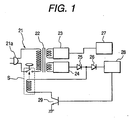
- FIG. 1 is a circuit diagram of a principal portion of a power supply circuit used in the electric apparatus
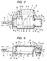
- Figs. 2 and 3 are a top view and a front view of a switch device used in the power supply circuit
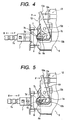
- Figs. 4 to 6 are enlarged diagrams of a principal portion of the switch device
- Figs. 7 and 8 are diagrams each explaining a relation between the operation of the switch device and that of a control circuit.
- the power supply circuit used in the electric apparatus (not shown) embodying the present invention as shown in the circuit diagram of Fig. 1 which illustrates a principal portion of the same circuit, comprises a primary power supply circuit 21 (hereinafter referred to simply as the "primary circuit 21") to which AC 100V is fed from a terminal 21a, a switch device S connected to the primary circuit 21 and having an auto-OFF function, and a secondary power supply circuit to which electric power fed to the primary circuit 21 is fed through a power transformer 22, the secondary power supply circuit comprising a power supply circuit 23 for both signal system and motor system and a power supply circuit 24 for a control system.
- the primary circuit 21 to which AC 100V is fed from a terminal 21a
- a switch device S connected to the primary circuit 21 and having an auto-OFF function
- a secondary power supply circuit to which electric power fed to the primary circuit 21 is fed through a power transformer 22
- the secondary power supply circuit comprising a power supply circuit 23 for both signal system and motor system and a power supply circuit 24 for a control
- the power supply circuit 23 for both signal system and motor system is connected to a signal system and motor system circuit 27.
- the power supply circuit 24 for a control system is connected via reverse current preventing diodes 25 and 26 to a control system circuit 28 constituted, for example, by a microcomputer having a reloadable memory (not shown) and also connected to the switch device S having two first and second switches 5 and 10 which will be described later. Electric power is fed to both control system circuit 28 and switch device S from the power supply circuit 24 for a control system.
- the control system circuit 28 and the switch device S are connected together via a driving transistor 29.
- a power supply circuit in the electric apparatus embodying the present invention is thus configured schematically.
- a frame 1 constituted by a metallic plate obtained by punching with a press or the like is disposed at an upper position.
- the frame 1 is formed with an AC switch portion 2 for mounting a first switch 5 which is a switch for an AC circuit to be described later and a drive source mounting portion 4 for mounting a drive source 12 to be described later, the AC switch portion 2 and the drive source mounting portion 4 being formed adjacent each other.
- a DC switch portion 3 On the right-hand side in the figure of the AC switch portion 2 is provided a DC switch portion 3 for mounting a second switch 10 which is a switch for a DC circuit to be described later, with a connecting portion 1c being formed between the AC switch portion 2 and the DC switch portion 3.
- the AC switch portion 2 has a stepped portion 2a which is partially projected in a flat shape.
- the stepped portion 2a is formed with a downwardly projecting lug 2b.
- first tongue-like caulking portions 2c vertically, which are bent downward as shown in Fig. 3.
- the DC switch portion 3 of the frame 1 is formed in a gate shape by vertically bending a pair of side plates 3b shown in Fig. 2.
- the paired side plates 3b are each formed with such second tongue-like caulking portions 3c as shown in Fig. 3, and projections 11b of a second case 11 to be described later are each caulked between the second caulking portions 3c to retain the second switch 10 which will be described later.
- retaining portions 3e for retaining a rear portion of the first switch 5 to be described later are formed as cutout portions in the positions where the side plates 3b and the connecting portion 1c are contiguous to each other.
- the size of a gap formed between the retaining portion 3e and the underside of the connecting portion 1c is set a little larger than the thickness of a lid 9 which will be described later.
- the drive source mounting portion 4 comprises a front side plate 4a, a rear side plate 4b and an upper side plate 4c, which side plates are formed by bending.
- the two first caulking portions 2c of the AC switch portion 2, the two side plates 3b of the DC switch portion 3, and the front side plate 4b, rear side plate 4c and side plate 4d of the drive source mounting portion 4 are bent downward in the same direction in Fig. 3.
- the first switch 5, which is an AC switch mounted to the AC switch portion 2 of the frame 1, has a first case 6.
- the first case 6 is formed of a resin material and has an upper opening.
- the first case 6 is formed with a forwardly projecting guide portion 6a, and a recess 6b is formed in a lower position of an outer surface of the guide portion 6a.
- the first switch 5 has a fixed contact and a movable contact (neither shown) both disposed within the first case 6 and is further provided with an operating member 7 for operating the fixed contact and the movable contact ON and OFF.
- the operating member 7 is slidable in the directions of arrows E and F.
- the operating member 7 is formed of a resin material and has an operating shaft 7a projecting outward from the front side of the first case 6.
- the operating shaft 7a is internally provided with a resilient member (not shown) for urging the operating member 7 in the arrow E direction at all times.
- the operating member 7 is partially formed with such a cam recess 7b as shown in Fig. 4.
- a cam bottom 7c In the cam recess 7b is formed a cam bottom 7c at a predetermined depth by cutting, the cam bottom 7c comprising a plurality of flat surfaces of different depths and a slant surface which connects the flat surfaces.
- a lock portion 8a of a lock member 8 which will be described later comes into abutment with the locking wall 7d, whereby the operating member 7 can be retained in a locked state.
- the lock member 8 which is a metallic rod, is disposed in the cam recess 7b. Both end portions of the lock member 8 are bent approximately at right angles and with the lock portion 8a being formed at one end portion, the other end portion serving as a fulcrum (not shown) and being supported on the first case 6 side.
- the lock portion 8a can move pivotally on the cam bottom 7c.
- the lock member 8 comes into abutment with the locking wall 7d while being guided by the cam bottom 7c, whereby the operating member 7 is locked and is inhibited its movement in the arrow E direction.
- the first switch 5 is turned ON and electric power is fed to the primary circuit 21 in the power circuit shown in Fig. 1.
- the lid 9 On top of the first case 6 is disposed a lid 9 of a metallic plate which closes an opening (not shown) of the first case 6. As shown in Fig. 3, the lid 9 is formed with a pair of base mounting portions 9b and a front caulking portion 9c both on the front side, which are bent downward.
- the lid 9 is formed with a pair of front retaining portions 9d projecting from the first case 6 at positions sandwiched between the frame 1 and the first caulking portions 2c shown in Fig. 2.
- a pair of rear retaining portions 9g are formed projectingly on a rear side in Fig. 2 of the lid 9.
- a rear caulking portion (not shown) is bent downward at a position between the rear retaining portions 9g and the lid 9 is rendered integral with the first case portion 6 by caulking both front caulking portion 9c and rear caulking portion to the first case 6.
- the rear retaining portions 9g are engaged with the retaining portions 3e of the frame 1 and the front retaining portions 9d are caulked to the first caulking portions 2c of the frame 1, whereby the first switch 5 constituted by such an AC switch as described above is mounted to the AC switch portion 2 of the frame 1.
- a second switch 10 which is a DC switch, is mounted to the DC switch portion 3 of the frame 1.
- the second switch 10 has a second case 11 formed of the same resin material as that of the first case 6, and as shown in Fig. 2, projections 11b are formed vertically from side walls 11a of the second case 11.
- the projections 11b are caulked by the caulking portions 3c, whereby the second switch 10 is mounted to the DC switch portion 3 of the frame 1.
- an operating rod (not shown) projecting from the second case 11 toward the first switch 5 is formed on the lower surface side of the frame 1. Interlockedly with a sliding motion in the arrow E or F direction of the operating member 7 the operating rod slides and the second switch 10 turns ON and outputs an ON signal upon turning ON of the first switch 5, while upon turning OFF of the first switch 5 the second switch 10 also turns OFF and outputs an OFF signal.
- Such ON and OFF signals from the second switch 10 are detected by a control system circuit 28 used in the power supply circuit shown in Fig. 1.
- the drive source 12 comprises a coil (not shown) and a moving core 12a. The coil is held grippingly between the front and rear side plates 4a, 4b of the frame 1 and is thereby prevented from dislodgment.
- the moving core 12a When the coil is energized from an initial deenergized state into an energized state, the moving core 12a is attracted in the direction of arrow P with a predetermined attractive force.
- An engaging portion 13a of a drive member is engaged with a front end of the moving core 12a.
- the drive member 13 is provided at one end with the engaging portion 13a and at the other end with a cam surface 13b, with a support hole 13c being formed in a position between the engaging portion 13a and the cam surface 13b.
- the engaging portion 13a of the drive member 13 is engaged with a front end of the moving core 12b and the support hole 13c thereof is fitted on the lug 2b of the frame 1, whereby the drive member 13 is mounted to the frame 1 pivotably with the support hole 13c as a center.
- the switch device S connected to the primary circuit 21 in the electric apparatus embodying the invention has the operating member 7 capable of being operated ON manually and OFF automatically and also has the drive source 12 capable of actuating the operating member 7 automatically to turn OFF the first and second switches 5, 10 automatically.
- the switch device S comprising these components is connected to the primary circuit 21.
- control system circuit 28 when the control system circuit 28 detects an ON or OFF signal outputted from the second switch 10 during ON or OFF operation of the switch device S connected to the primary circuit 21, the control system circuit writes information such as "0" or "1" into a memory (not shown) formed in the same circuit.
- the lock member 8 is positioned away from the locking wall 7d (a solid black portion).
- an ON signal (information of "0") is outputted.
- the control system circuit 28 detects this ON signal, it collates information pre-stored in initialization in the memory of the control system circuit 28, for example, "0" information with the ON signal from the second switch 10, and if both are coincident with each other, the control system circuit rewrites information "0" to "1" in the memory.
- the operation of the electric apparatus can be stopped by operating the switch device S manually or automatically to turn OFF the power supply circuit of the electric apparatus.
- the electric apparatus which is in normal operation can be turned OFF manually in the following manner.
- the lock member 8 positioned in the cam recess 7b is guided by the cam bottom 7c and is disengaged from the locking wall 7d, so that the operating member 7 is unlocked.
- the electric apparatus which is in normal operation can be turned OFF automatically in the following manner.
- the control system circuit 28 detects a control signal issued from a timer installed in the electric apparatus or from a remote controller or the like, electric power is fed to the drive source 12 in accordance with a command issued from the circuit 28, so that the moving core 12a is attracted in the arrow P direction.
- the drive member 13 turns clockwise with the support hole 13c as a center and, as shown in Fig. 6, the cam surface 13b of the drive member 13 is positioned on the locking wall 7d and pushes the lock member 8 upward, whereby the lock member 8 is disengaged from the locking well 7d and the operating member 7 is unlocked from the locked state.
- the operating member 7 When the operating member 7 is unlocked, the operating member 7 is returned in the arrow E direction by virtue of the resilient member (not shown), the second switch 10 and the first switch 5 are turned OFF automatically in this order, the switch device S reverts to its initial state automatically. Then, the power supply circuit is turned OFF automatically and thus the operation of the electric apparatus can be stopped.
- an OFF signal (information of "1") is outputted and the control system circuit 28 detects this OFF signal and rewrites information from "1" to "0.”
- the supply of electric power to the primary circuit 21 is interrupted and the supply of electric power to the secondary circuit comprising the signal and motor system power supply circuit 23 and the signal system power supply circuit 24 is also interrupted, whereby the consumption of stand-by electric power (cold reserve) can be made zero.
- the power supply of the electric apparatus can again be turned ON normally by operating the switch device S in accordance with the procedure described above to control the control system circuit 28.
- the control system circuit 28 determines that the result is NG and that the ON operation of the switch device S is not in normal condition but in abnormal condition.
- control system circuit 28 determines that the ON operation is in abnormal condition, electric power is fed to the drive source 12 of the switch device S in accordance with a command issued from the control system circuit. Consequently, the drive source 12 is operated, the operating member 7 is unlocked, the second switch 10 and the first switch 5 are turned OFF automatically in this order to cut off the supply of electric power to the primary circuit 21, and the operation of the electric apparatus is stopped automatically. Thus, it is possible to make sure whether any trouble has occurred or not in the electric apparatus during power failure.
- an OFF signal (information of "1") is outputted from the second switch 10 and the control system circuit 28 detects this OFF signal and rewrites the memory contents from information "1" to "0,” thus indicating that the power supply circuit of the electric apparatus has been turned OFF in normal operation.
- the memory contents are rewritten unconditionally when the second switch 10 is OFF, while when the second switch 10 is ON, the memory contents are rewritten on the basis of the result of comparison between the memory contents and the signal provided from the second switch 10.
- the electric apparatus constructed as above is a drying machine for example and upon occurrence of a dangerous act, for example, in the event a child opens the lid and enters the interior of the drying machine when the machine is OFF in an abnormal condition such as power failure, the control system circuit 28 detects a rise from the abnormal condition after restoration and before restart-up of operation of the drying machine and causes the switch device S to operate automatically, thereby making it possible to stop the restart-up of operation of the drying machine.
- control system circuit 28 causes the power supply circuit to turn OFF in an instant and the operation of the electric apparatus can be resumed after making sure if any trouble has occurred or not in the electric apparatus during power failure.
- the switch device has first and second switches and the operating member can be held in a locked state manually and in an unlocked state manually or automatically.
- the first and second switches are turned ON, while when the operating member is unlocked, both switches are turned OFF.
- the supply of electric power to the primary power supply circuit is controlled in accordance with ON/OFF operation of the first switch, and the second switch outputs an ON or OFF signal, which is detected by the control system circuit.
- the first and second switches can be operated ON and OFF simultaneously by operation of the operating member and it is possible to provide an electric apparatus provided with a switch device superior in operability.
- the primary circuit can be turned OFF by the first switch, it is possible to provide an electric apparatus with reduced consumption of stand-by electric power (cold reserve).
- the switch device has a drive source capable of actuating the operating member automatically and thereby turning OFF the first and second switches automatically.
- the second switch can output ON and OFF signals in response to operation of the operating member and these signals are detected by the control system circuit, which in turn rewrites the memory contents at every switch-over between the ON and OFF signals.
- the control system circuit collates the ON signal outputted from the second switch with the contents stored in the memory, and in accordance with the result of this collation the control system circuit makes control to continue the supply of electric power to the primary power supply circuit or causes the drive source to turn OFF the switch device automatically, thereby interrupting the supply of electric power to the primary power supply circuit.
- control system circuit upon restoration from power failure for example, the control system circuit detects a rise from an abnormal condition and makes control to turn OFF the primary circuit automatically, thereby once stopping the operation.
- the operation can be resumed after checking whether any trouble has occurred or not during power failure, thereby permitting the provision of a highly safe electric apparatus.
Landscapes
- Engineering & Computer Science (AREA)
- Textile Engineering (AREA)
- Push-Button Switches (AREA)
- Power Sources (AREA)
- Remote Monitoring And Control Of Power-Distribution Networks (AREA)
- Supply And Distribution Of Alternating Current (AREA)
Claims (3)
- Elektrisches Gerät, aufweisend:dadurch gekennzeichnet, dass das elektrische Gerät ferner Folgendes aufweist:einen primären Stromversorgungskreis;einen sekundären Stromversorgungskreis, dem elektrische Energie von dem primären Stromversorgungskreis zugeführt wird;eine Steuersystemschaltung, die mit dem sekundären Stromversorgungskreis verbunden ist;eine Schaltervorrichtung mit einem Betätigungselement, das sich manuell in den Ein-Zustand bringen lässt und sich manuell oder automatisch in den Aus-Zustand bringen lässt,wobei die Schaltervorrichtung mit dem primären Stromversorgungskreis verbunden ist, undeinen Speicher, in dem ein bei Ein- oder Aus-Betätigung der Schaltervorrichtung abgegebenes Signal nach dessen Detektion durch die Steuersystemschaltung gespeichert wird,
wobei die Steuersystemschaltung dertart konfiguriert ist, dass nach dem Starten der Zufuhr von elektrischer Energie zu dem primären Stromversorgungskreis die Steuersystemschaltung feststellt, ob die Schaltervorrichtung in den Ein-Zustand gebracht worden ist oder nicht, und zwar durch Vergleichen mit dem in dem Speicher gespeicherten Inhalt, sowie eine Steuerung zum Fortsetzen oder Unterbrechen der Zufuhr von elektrischer Energie zu dem primären Stromversorgungskreis in Abhängigkeit von dem Ergebnis des Vergleichs vornimmt. - Elektrisches Gerät nach Anspruch 1,
wobei die Schaltervorrichtung einen ersten Schalter und einen zweiten Schalter aufweist, wobei das Betätigungselement manuell in einem verriegelten Zustand gehalten werden kann oder manuell oder automatisch in einem entriegelten Zustand gehalten werden kann, wobei der erste und der zweite Schalter eingeschaltet werden, wenn sich das Betätigungselement in dem verriegelten Zustand befindet, während dann, wenn das Betätigungselement in dem entriegelten Zustand ist, der erste und der zweite Schalter ausgeschaltet sind, wobei die Zufuhr von elektrischer Energie zu dem primären Stromversorgungskreis durch Ein-/Aus-Betätigung des ersten Schalters gesteuert wird und wobei der zweite Schalter ein Ein- oder Aus-Signal abgibt, das von der Steuersystemschaltung detektiert wird. - Elektrisches Gerät nach Anspruch 2,
wobei die Schaltervorrichtung eine Antriebsquelle aufweist, die in der Lage ist, das Betätigungselement automatisch zu betätigen, um den ersten und den zweiten Schalter automatisch auszuschalten, wobei das von dem zweiten Schalter abgegebene Ein- oder Aus-Signal von der Steuersystemschaltung detektiert wird und der in dem Speicher gespeicherte Inhalt bei jedem Umschalten der Ein- und Aus-Signale von dem einen in den anderen Zustand umgeschrieben wird, wobei die Steuersystemschaltung beim Einschalten des ersten Schalters und Beginn der Zufuhr von elektrischer Energie zu dem primären Stromversorgungskreis das von dem zweiten Schalter abgegebene Ein-Signal mit dem in dem Speicher gespeicherten Inhalt vergleicht und die Steuersystemschaltung in Abhängigkeit von dem Ergebnis des Vergleichs eine Steuerung zum Fortsetzen der Zufuhr von elektrischer Energie zu dem primären Stromversorgungskreis vornimmt oder die Antriebsquelle zum automatischen Ausschalten der Schaltervorrichtung veranlasst, um dadurch die Zufuhr von elektrischer Energie zu dem primären Stromversorgungskreis zu unterbrechen.
Applications Claiming Priority (2)
| Application Number | Priority Date | Filing Date | Title |
|---|---|---|---|
| JP10360944A JP2000184598A (ja) | 1998-12-18 | 1998-12-18 | 電気機器 |
| JP36094498 | 1998-12-18 |
Publications (3)
| Publication Number | Publication Date |
|---|---|
| EP1016752A2 EP1016752A2 (de) | 2000-07-05 |
| EP1016752A3 EP1016752A3 (de) | 2002-06-26 |
| EP1016752B1 true EP1016752B1 (de) | 2003-10-29 |
Family
ID=18471562
Family Applications (1)
| Application Number | Title | Priority Date | Filing Date |
|---|---|---|---|
| EP99125120A Expired - Lifetime EP1016752B1 (de) | 1998-12-18 | 1999-12-16 | Elektrisches Gerät mit automatischer Stromabschaltung , zum Vermeiden der Wiederinbetriebnahme, bis die Betriebsicherheit gewährleistet ist , zur Zeit des Neustarts, nach störungsbedingtem Stop |
Country Status (4)
| Country | Link |
|---|---|
| US (1) | US6291910B1 (de) |
| EP (1) | EP1016752B1 (de) |
| JP (1) | JP2000184598A (de) |
| DE (1) | DE69912387T2 (de) |
Families Citing this family (7)
| Publication number | Priority date | Publication date | Assignee | Title |
|---|---|---|---|---|
| JP3722634B2 (ja) * | 1998-12-09 | 2005-11-30 | アルプス電気株式会社 | 電気機器 |
| US7453677B2 (en) * | 2004-10-06 | 2008-11-18 | Teknic, Inc. | Power and safety control hub |
| KR101158060B1 (ko) * | 2005-07-01 | 2012-06-18 | 엘지전자 주식회사 | 세탁기의 대기전력 제어장치 및 그 방법 |
| DE102007058379A1 (de) * | 2007-12-05 | 2009-06-10 | BSH Bosch und Siemens Hausgeräte GmbH | Schaltungsanordnung zum Betreiben eines Hausgeräts |
| JP6253237B2 (ja) * | 2013-02-25 | 2017-12-27 | 東芝ライフスタイル株式会社 | ランドリー機器 |
| JP2018027445A (ja) * | 2017-11-28 | 2018-02-22 | 東芝ライフスタイル株式会社 | ランドリー機器 |
| CN112760915A (zh) * | 2020-12-18 | 2021-05-07 | 珠海格力电器股份有限公司 | 洗衣机及其控制方法 |
Family Cites Families (7)
| Publication number | Priority date | Publication date | Assignee | Title |
|---|---|---|---|---|
| US3713226A (en) * | 1970-10-20 | 1973-01-30 | Matsushita Electric Industrial Co Ltd | Clothes dryer |
| US4451865A (en) * | 1981-05-18 | 1984-05-29 | The Singer Company | Electrical cutout for under voltage or power loss conditions |
| US4466040A (en) * | 1982-05-10 | 1984-08-14 | The Singer Company | Safety device |
| KR100235897B1 (ko) | 1994-09-01 | 1999-12-15 | 전주범 | 세탁기의 급수 밸브 제어방법 |
| DE19628723C2 (de) * | 1996-07-17 | 2002-10-02 | Aeg Hausgeraete Gmbh | Elektrisches Haushaltsgerät, insbesondere elektrischer Wäschetrockner |
| US6081047A (en) * | 1997-11-13 | 2000-06-27 | Micron Technology, Inc. | Apparatus and method of resetting an electric device |
| US6208042B1 (en) * | 1999-04-05 | 2001-03-27 | Gilbert Solis | Anti-reactivation safety device |
-
1998
- 1998-12-18 JP JP10360944A patent/JP2000184598A/ja active Pending
-
1999
- 1999-12-02 US US09/453,264 patent/US6291910B1/en not_active Expired - Fee Related
- 1999-12-16 EP EP99125120A patent/EP1016752B1/de not_active Expired - Lifetime
- 1999-12-16 DE DE69912387T patent/DE69912387T2/de not_active Expired - Fee Related
Also Published As
| Publication number | Publication date |
|---|---|
| EP1016752A2 (de) | 2000-07-05 |
| US6291910B1 (en) | 2001-09-18 |
| DE69912387D1 (de) | 2003-12-04 |
| DE69912387T2 (de) | 2004-08-05 |
| JP2000184598A (ja) | 2000-06-30 |
| EP1016752A3 (de) | 2002-06-26 |
Similar Documents
| Publication | Publication Date | Title |
|---|---|---|
| US4910634A (en) | Interlock switch | |
| US6392903B2 (en) | Electronic equipment adapted to reduce power consumption during no operation | |
| US5879036A (en) | Door interlock for an appliance such as a washer | |
| US6304008B1 (en) | Electronic device having auto-off or auto-on/off function | |
| EP1016752B1 (de) | Elektrisches Gerät mit automatischer Stromabschaltung , zum Vermeiden der Wiederinbetriebnahme, bis die Betriebsicherheit gewährleistet ist , zur Zeit des Neustarts, nach störungsbedingtem Stop | |
| JPH11505000A (ja) | スイッチ内蔵キャビネットの扉、機械装置ハウジング等を施錠するための保安装置 | |
| KR0164762B1 (ko) | 세탁기의 자동도어 개폐장치의 제어방법 | |
| US4866955A (en) | Appliance control circuit | |
| US6445090B1 (en) | Electrical equipment having energy saving mode capable of shutting off supplying of voltage to primary power supply supplying circuit under no use thereof | |
| JP2721622B2 (ja) | 安全用スイッチ装置 | |
| JP2009261927A (ja) | 家庭用電気製品 | |
| JP2002280769A (ja) | 基板誤抜去防止装置 | |
| JP2001165393A (ja) | インタロック機構を備えた制御盤 | |
| EP0194248B1 (de) | Unabsichtliche Öffnungsverhütungsvorrichtung für gegen Einbruch gesicherte Türen | |
| JP2721634B2 (ja) | 安全用スイッチ装置のコンタクトブロック | |
| JP2564371Y2 (ja) | 安全用スイッチ装置 | |
| JP2002236072A (ja) | 漏水検出装置 | |
| KR200176880Y1 (ko) | 고주파 카드식 전자개폐기의 소비전력 절감장치 | |
| JP4805904B2 (ja) | 電気機器及び洗濯機 | |
| JP2721621B2 (ja) | 安全用スイッチ装置 | |
| JP2000275922A (ja) | 画像形成装置 | |
| KR100279211B1 (ko) | 카세트의소거방지핑거를검출하는레버 | |
| EP1006542B1 (de) | Schaltervorrichtung | |
| JP2605945Y2 (ja) | 安全用スイッチ装置のコンタクトブロック | |
| JP2002004666A (ja) | ロック式の扉を有する電気機器 |
Legal Events
| Date | Code | Title | Description |
|---|---|---|---|
| PUAI | Public reference made under article 153(3) epc to a published international application that has entered the european phase |
Free format text: ORIGINAL CODE: 0009012 |
|
| AK | Designated contracting states |
Kind code of ref document: A2 Designated state(s): AT BE CH CY DE DK ES FI FR GB GR IE IT LI LU MC NL PT SE |
|
| AX | Request for extension of the european patent |
Free format text: AL;LT;LV;MK;RO;SI |
|
| RIN1 | Information on inventor provided before grant (corrected) |
Inventor name: KAORU SOETA C/O ALPS ELECTRIC CO,LTD Inventor name: KATSUHIKO TOCHIHARA C/O ALPS ELECTRIC CO,LTD Inventor name: TOSHIHARU MORI C/O ALPS ELECTRIC CO |
|
| PUAL | Search report despatched |
Free format text: ORIGINAL CODE: 0009013 |
|
| AK | Designated contracting states |
Kind code of ref document: A3 Designated state(s): AT BE CH CY DE DK ES FI FR GB GR IE IT LI LU MC NL PT SE |
|
| AX | Request for extension of the european patent |
Free format text: AL;LT;LV;MK;RO;SI |
|
| RIC1 | Information provided on ipc code assigned before grant |
Free format text: 7D 06F 58/04 A, 7D 06F 58/28 B, 7D 06F 33/02 B, 7F 16P 3/08 B |
|
| 17P | Request for examination filed |
Effective date: 20020717 |
|
| AKX | Designation fees paid |
Designated state(s): DE FR GB |
|
| GRAH | Despatch of communication of intention to grant a patent |
Free format text: ORIGINAL CODE: EPIDOS IGRA |
|
| GRAS | Grant fee paid |
Free format text: ORIGINAL CODE: EPIDOSNIGR3 |
|
| GRAA | (expected) grant |
Free format text: ORIGINAL CODE: 0009210 |
|
| AK | Designated contracting states |
Kind code of ref document: B1 Designated state(s): DE FR GB |
|
| REG | Reference to a national code |
Ref country code: GB Ref legal event code: FG4D |
|
| REG | Reference to a national code |
Ref country code: IE Ref legal event code: FG4D |
|
| REF | Corresponds to: |
Ref document number: 69912387 Country of ref document: DE Date of ref document: 20031204 Kind code of ref document: P |
|
| ET | Fr: translation filed | ||
| PLBE | No opposition filed within time limit |
Free format text: ORIGINAL CODE: 0009261 |
|
| STAA | Information on the status of an ep patent application or granted ep patent |
Free format text: STATUS: NO OPPOSITION FILED WITHIN TIME LIMIT |
|
| REG | Reference to a national code |
Ref country code: IE Ref legal event code: MM4A |
|
| 26N | No opposition filed |
Effective date: 20040730 |
|
| PGFP | Annual fee paid to national office [announced via postgrant information from national office to epo] |
Ref country code: FR Payment date: 20061215 Year of fee payment: 8 |
|
| PGFP | Annual fee paid to national office [announced via postgrant information from national office to epo] |
Ref country code: GB Payment date: 20071220 Year of fee payment: 9 |
|
| PGFP | Annual fee paid to national office [announced via postgrant information from national office to epo] |
Ref country code: DE Payment date: 20080227 Year of fee payment: 9 |
|
| REG | Reference to a national code |
Ref country code: FR Ref legal event code: ST Effective date: 20081020 |
|
| PG25 | Lapsed in a contracting state [announced via postgrant information from national office to epo] |
Ref country code: FR Free format text: LAPSE BECAUSE OF NON-PAYMENT OF DUE FEES Effective date: 20071231 |
|
| GBPC | Gb: european patent ceased through non-payment of renewal fee |
Effective date: 20081216 |
|
| PG25 | Lapsed in a contracting state [announced via postgrant information from national office to epo] |
Ref country code: DE Free format text: LAPSE BECAUSE OF NON-PAYMENT OF DUE FEES Effective date: 20090701 |
|
| PG25 | Lapsed in a contracting state [announced via postgrant information from national office to epo] |
Ref country code: GB Free format text: LAPSE BECAUSE OF NON-PAYMENT OF DUE FEES Effective date: 20081216 |