EP1016522A1 - Schnellwechselvorrichtung für eine Druckmaschine - Google Patents
Schnellwechselvorrichtung für eine Druckmaschine Download PDFInfo
- Publication number
- EP1016522A1 EP1016522A1 EP99122777A EP99122777A EP1016522A1 EP 1016522 A1 EP1016522 A1 EP 1016522A1 EP 99122777 A EP99122777 A EP 99122777A EP 99122777 A EP99122777 A EP 99122777A EP 1016522 A1 EP1016522 A1 EP 1016522A1
- Authority
- EP
- European Patent Office
- Prior art keywords
- carriage
- press
- frame
- anilox roll
- lifting
- Prior art date
- Legal status (The legal status is an assumption and is not a legal conclusion. Google has not performed a legal analysis and makes no representation as to the accuracy of the status listed.)
- Granted
Links
Images


Classifications
-
- B—PERFORMING OPERATIONS; TRANSPORTING
- B41—PRINTING; LINING MACHINES; TYPEWRITERS; STAMPS
- B41F—PRINTING MACHINES OR PRESSES
- B41F5/00—Rotary letterpress machines
- B41F5/24—Rotary letterpress machines for flexographic printing
-
- B—PERFORMING OPERATIONS; TRANSPORTING
- B41—PRINTING; LINING MACHINES; TYPEWRITERS; STAMPS
- B41F—PRINTING MACHINES OR PRESSES
- B41F13/00—Common details of rotary presses or machines
- B41F13/08—Cylinders
- B41F13/24—Cylinder-tripping devices; Cylinder-impression adjustments
-
- B—PERFORMING OPERATIONS; TRANSPORTING
- B41—PRINTING; LINING MACHINES; TYPEWRITERS; STAMPS
- B41F—PRINTING MACHINES OR PRESSES
- B41F31/00—Inking arrangements or devices
- B41F31/30—Arrangements for tripping, lifting, adjusting, or removing inking rollers; Supports, bearings, or forks therefor
-
- B—PERFORMING OPERATIONS; TRANSPORTING
- B41—PRINTING; LINING MACHINES; TYPEWRITERS; STAMPS
- B41P—INDEXING SCHEME RELATING TO PRINTING, LINING MACHINES, TYPEWRITERS, AND TO STAMPS
- B41P2213/00—Arrangements for actuating or driving printing presses; Auxiliary devices or processes
- B41P2213/80—Means enabling or facilitating exchange of cylinders
- B41P2213/804—Means enabling or facilitating exchange of cylinders radially
Definitions
- This invention relates to printing presses, and, more particularly, to a quick change system for a press such as a flexographic press.
- the multicolor flexographic printing process requires the use of components specific to each job. These components consist of the following:
- All of these components need to be exchangeable. There may be situations where an unfavorable anilox roll will be changed during a run. A plate cylinder change may be the only component change if the same ink is going to be used on the next job. Perhaps the ink mixture is not producing the desired print quality and needs to be replaced. A common changeover will require all components to be exchanged in preparation for a completely new print run.
- a typical wide web central impression printing press will be provided with some means of operator assistance for component exchange. Operator assistance is required since the plate rolls can weigh up to 800 pounds or more and the anilox rolls can weight in the range of 500 pounds. Operator assistance includes:
- a gravure press also incorporates a cart system to decrease the changeover time.
- a gravure cart is wheeled into place and is always on the floor. The cart is larger, but the gravure application has the advantage of space because the process does not require printing on a central impression drum.
- a gravure press like most narrow web presses uses an in-line configuration that does not print quality (color-to-color register within 0.003 inch) images on extensible webs. These cartridges in both cases also have the problem of not being able to replace the print cylinder without replacing the cartridge.
- the goal of this invention is to create a wide web printing press of the type described above that can obtain a significant decrease in changeover time. Fifteen minutes or less changeovers would be a proper goal with today's shorter runs.
- the invention provides such a design, based upon the changeover study and the criteria listed.
- This design consists of three major components:
- the robot functions as a three-point "pick and choose" system.
- the robot transports components by three lifting cups on each side of the press. These cylinder-actuated cups will be either extended or retracted. When all of the cups are fully extended, a complete color deck changeover can be made. One lifting point will pick up the plate cylinder journals, the next will pick up the anilox roll journals, and the third will pick up the color deck carriage.
- the lifting cups can also lift the plate roll alone, the anilox roll alone, the plate and anilox roll together, or the anilox roll with carriage.
- a conventional flexographic press 20 includes a pair of side frames 21 which support a plurality of color decks 22.
- the press includes six color decks 22a-22f.
- a central impression cylinder 23 is rotatably mounted on the frames.
- Each of the color decks supports a plate cylinder or roll 25, an anilox roll 26, and a color deck carriage 27.
- the carriage 27 includes the ink system for the press.
- the plate cylinders and the anilox rolls are shown in their racked-out, non-operating positions in Figure 1.
- the plate cylinders When the press is operating, the plate cylinders are adjacent the surface of the central impression cylinder, and the anilox rolls contact the plate cylinders. Ink is thereby transferred to the plate cylinders, and images are transferred to a web which rotates with the central impression cylinder.
- each plate cylinder and anilox rolls are advantageously mounted on the color decks so that each plate cylinder and each anilox roll can be removed from the color deck independently of the color deck carriage 27.
- each anilox roll can be removed from the color deck with the carriage, or all three components can be removed simultaneously.
- First and second staging areas or make ready areas 30 and 31 are located adjacent the two sides of the press for supporting the components of the color decks for the next run of the press.
- the components for the color decks 22a-22c are located in the staging area 30, and the components for the color decks 22d-22f are located in the staging area 31.
- Each staging area includes a pair of support frames 33, and each support frame includes four support decks 34-37.
- each of the support decks 35-37 supports a plate cylinder 25, an anilox roll 26, and color deck carriage 27 for one of the color decks of the press.
- the upper support deck 34 is empty and provides a location to which the components of one of the color decks can be moved during changeover.
- Each plate cylinder includes a pair of laterally extending journals 38 which are supported by the support frame 33.
- the anilox rolls include journals 39
- the color deck carriages include dead journals or non-rotating shafts 40 which are also supported by the support frames 33.
- the deck components for the next press run are not shown in Figures 1 and 2 for clarity of illustration.
- the components of the color decks are transported between the color decks 22 and the staging areas by a pair of robot assemblies 41 and 42.
- the robot 41 moves between the color decks 22a-22c and the staging area 30.
- the robot 42 moves between the color decks 22d-22f and the staging area 31.
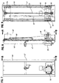
- the robot 41 includes horizontal rails 43 for movement in one horizontal axis, and the rails 43 are slidably mounted on perpendicular rails 44 so that the robot can move in a second horizontal axis.
- the robot 42 moves in only one horizontal axis on rails 45, but the robot 42 could be mounted for movement in another horizontal axis if desired.
- Rails 43-45 are purchased linear motion modules, such as STAR MKR 25-145 or 25-110.
- Each of the rails 43-45 includes a sliding base 43a, 44a, 45a (Figs. 4 and 5) respectively, which is supported by linear motion bearing blocks traveling upon a linear rail and which is driven by a toothed belt which is clamped to the sliding base.
- the sliding base 43a and 45a on the rails 43 and 45 provide a mounting platform for the vertically extending modules 46 of the robots 41 and 42.
- the sliding bases 44a on the rails 44 provide a mounting platform for the rails 43.
- Each of the robots includes a pair of modules 46, and each module is bolted to one of the sliding bases 43a and 45a which are slidably supported on the rails 43 and 45.
- each of the modules includes a vertically extending frame 47 and a pick-up carriage 48 which is movable vertically along the frame.
- the pick-up carriage is guided by two sets of linear motion bearing blocks 49 (Fig. 10) traveling upon a pair of vertical rails 50.
- the bearing blocks and linear rails provide smooth operation and high load carrying capacity.
- the pick up carriage is driven through a ball screw assembly consisting of a driven ball screw 51, which is secured to the vertical support structure with a fixed pillow block bearing 52 (Fig. 9) at the bottom and a floating pillow block bearing 53 at the top, and a threaded nut housing 54 attached to the pick up carriage.
- the ball screw is driven by a motor 55 such as an Indramat DDS servo motor.
- the lower position of the pick-up carriage is shown in solid outline in Figure 8, and the upper position is shown in dotted outline at 48'.
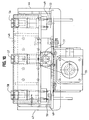
- Three extendible and retractable lifting cups 56, 57, and 58 are mounted on the pick-up carriage.
- each of the lifting cups 56-58 includes a cylindrical rear end 60 (Fig. 13) and a semi-cylindrical front end 61.
- the cylindrical rear end is slidably mounted in a cylinder 63, and the lifting cup is reciprocated by a ram 64 of a pneumatic cylinder 65.
- the lifting cup 58 is shown in its extended position in Figure 13, and all of the lifting cups are shown in their retracted positions in Figure 12.
- Each of the pneumatic cylinders 65 can be operated independently so that each of the lifting cups can be extended or retracted independently of the other lifting cups.
- Air for the pneumatic cylinders is controlled by valve bank 66, distributed control input block 67, and distributed control output block 68. Air and electrical power are supplied to the movable pick-up carriage 48 by cable track 69 ( Figure 8).
- the robots 41 and 42 can function as a three-point "pick and choose" system.
- Each robot has the capability to transport components by the three lifting cups 56-58 on each side of the press.
- These cylinder-actuated cups will be either extended or retracted. When all of the cups are fully extended, a complete color deck changeover can be made.
- One pair of lifting cups will pick up the plate cylinder journals 38 (Fig. 6), another pair of cups will pick the anilox roll journals 39, and the third pair of cups will pick up the journals 40 of the carriage 27.
- Figure 17 illustrates the two pick-up carriages 48 of one of the robots lifting the plate cylinder 25, anilox roll 26 and color deck carriage 27 of one of the color decks of the press.
- the ends of the journals 38-40 are supported by the lifting cups 56-58.
- the anilox roll is rotatably mounted on, and removably connected to, the color deck carriage by conventional journals caps 71.
- the color deck carriage is supported by both the anilox journals 39 and the dead journals 40.
- the lifting carriage could have only two lifting cups.
- the plate cylinder journals 38 and anilox roll journals 39 are rotatably and removably mounted on the frame of the flexographic press in the conventional manner by bearing caps or journal caps.
- the non-rotating journals 40 of the color deck carriages are not supported in the color deck of the press. It is very important to the design that location of the carriage is based only on the anilox roll bearing caps.
- the carriage is supported by the frame of the press, but essentially "floats" so that any inconsistencies of manufacturing of the carriage do not result in misalignment within the press.
- the plate rolls and anilox rolls are precisely located in the color deck of the press by the bearing caps-or journal caps.
- the carriage 27, which is tied to the anilox roll, cannot bottom itself out prior to the anilox bottoming out within its bearing cap. This design will maintain the precision of the deck and the quality of the print over the lift of the machine.
- the components of a color deck are removed from the press by positioning the lifting cups of the pick-up carriage below the journals, opening the journal caps which hold the journals on the frame of the press, and then raising the pick-up carriages.
- the semi-cylindrical ends of the lifting cups capture the ends of the journals and lift the components out of the journal caps and out of the press.
- the robot is then moved to transport the components to the make-ready area.
- the robot can exchange all components required for a complete changeover. It can also select the plate roll, the anilox roll, the plate and anilox rolls, or the anilox roll with carriage individually.
- the lifting cups for the components which will be changed are extended so that the lifting cups engage the journals of those components.
- the other lifting cups are retracted so that they do not engage the journals of the components which will not be changed.
- journal caps 71 are opened so that the anilox roll can be lifted out of the carriage 27.
- Each robot is driven horizontally by an electric motor 72 (Figs. 4 and 5) through a drive such as an Indramat servo drive and motor controlled by a motion control system located in a control cabinet 74 near the press section.
- the motor drives through a gear box to achieve a torque reduction between the motor and the load.
- Motors 72 are used to drive the sliding bases 43a and 45a, and each motor moves the associated robot in a first horizontal direction into and out of the press.
- a torque tube 75 or cross drive links the two vertical modules 46 of each robot so that they travel together horizontally.
- Motor 73 is used to drive the sliding bases 42a and moves robot 41 in the second horizontal direction between the press and the staging structure 30.
- a torque tube 76 or similar device links each module of the robot so that they travel together. Depending upon the size of the load, the torque tube may not be necessary.
- the motion control system can be a motion controller such as a Giddings & Lewis PIC 945 and provides the commands to each motor/drive combination.
- the commands to each drive will enable the robot to move the deck components in a programmed path that will avoid obstacles.
- the operator of the system will select the source location and the destination of the component or components that need to be moved.
- the motion control system will calculate and control the location of each axis throughout the entire motion profile.
- each of the color deck carriages 27 includes a frame 80 for supporting an anilox roll 26 and the ink handling system 81 for a single color deck.
- the ink handling system 81 includes a doctor blade assembly 82, an ink container 83, a pump 84, a viscosity control system 85, a drip containment pan 86, and required hoses and piping.
- Such components are well known, and a detailed description is unnecessary.
- the carriage 27 is independent of the press and provides a totally integrated ink delivery system.
- the entire carriage, including the anilox roll 26, is transported to and from the color deck by the robot.
- the carriage could also be transported by other means, such as a hoist system or other manual means.
- ink containers vary.
- a typical five gallon container 83 is illustrated.
- the container is shallow enough so that it does not interfere with obstructions on the deck.
- the ink container in this design travels with the carriage, which allows the hoses to and from the container to be relatively short.
- the length of hose is critical in preventing twists and kinks which cause pressure disturbance in ink flow and ultimately leaks in the system.
- An air driven stirrer 87 can also be included with the container to insure ink circulation.
- An alternative to the described ink container is a typical pail which is of a depth that would prevent the racking in movement of the carriage.
- This size container would collide with spacers or between color dryers. Provisions can be designed into a carriage to alleviate this problem.
- the robot see later description
- transports the carriage to the press via a programmed path, it will make a final downward movement.
- the ink container disengages from the carriage by bottoming itself out on a catch pin. After this disengagement the robot continues its downward movement and places the plate and anilox journals into their respective journal caps.
- the staging provides the means to prepare plate cylinders, anilox rolls, and color deck carriages for the next press run.
- Each staging area can include a conventional Sunday drive system, permitting anilox roll wash-up as well as ink-up prior to the next run. All clean-up, roll exchanges, and next job set up are accomplished while the press is running a job. This allows internal changeover tasks to be converted to external tasks as changeover process study requires.
- Converting many of the internal changeover tasks to external tasks substantially reduces machine downtime.
- the clean-up and make-ready tasks have been converted to external operations. These tasks still need to be accomplished before a typical two hour or less run is completed. The following is a description of the system which will perform these external operations.
- the anilox cylinder and plate cylinder can be staged in a cart 90 (Figs. 1 and 2). Carts do, however, cause problems of their own. They need to be moved either by personnel or by some automated conveying type system.
- the support system for the external operations improves this method by providing stationary staging areas 30 and 31 for all the color deck components.
- the framework can be positioned directly behind the press (31 in Fig. 4) or behind and laterally offset from the press (30 in Fig. 5).
- the framework 33 simulates the positions of the components within the press. There are cradles for the plate cylinder journals and supports for the carriage, which also contains the anilox roll and other components of the ink system. An empty area is required in the framework so that the robot has a place to transport the initial components from the press. With the staging framework, the robot can simply move components from the press directly to the clean-up/make ready area. There is no need for middleman devices such as roll carts to transport them to this area.
- An alternate embodiment does require roll carts for the changeover process.
- This method eliminates the space for the plate cylinders 25 within the framework 33.
- the robot would still remove all the components in the press at one time. It would, however, separate the plate cylinder from the other components and bring the plate cylinder to a cart either before or after the carriage is deposited in the framework.
- the time required to accomplish this detour should not comprise the fifteen minute or less changeover goal. It does, however, shorten the make-ready time and reduces the number of times the plate cylinders need to be handled.
- clean-up and make ready tasks can commence.
- the first task is clean-up. Doctor holders can be cleaned manually, by some automatic wash-up system, or by exchanging them with clean holders.
- the press is running, and clean-up at this time does not equate to down time. It does, however, still need to be done quickly enough to accommodate the next changeover.
- the automatic wash-up system is the quickest way to complete this task. After the system is activated, personnel can concentrate their efforts on other clean-up/make ready tasks.
- the operator can begin staging the plate cylinders for the next run.
- the plate cylinders for the next job are transported on carts from the plate room to the staging framework.
- the robot which was used for the primary exchange is used once again. This time it is making exchanges from the framework to and from the plate cylinder cart.
- the wash-up system continues its sequence while the plate cylinder exchanges are made.
- the next step in the make-ready process is the exchange of anilox rolls. Again, the robot is utilized to accomplish this task. Roll carts containing the desired anilox rolls are brought into position and the exchange takes place.
- Doctor holders can now be fitted with new blades and seals.
- the ink for the next job is brought into place.
- the final step of inking up will not occur until some predetermined time prior to changeover. This step is postponed as long as possible.
- the roll only needs to be inked up prior to the next changeover sequence. Accomplishing this task long before needed creates unnecessary VOC emissions, assuming solvent based inks are being used. However, time should be allotted to make ink or doctor setting modifications, if necessary.
- the staging framework will be equipped with a conventional Sunday drive system which will provide for the anilox roll rotation necessary for ink-up purposes. When the time arrives for ink-up, this system is activated. Color swatch samples can now be taken. The make-ready personnel can make whatever ink and setting changes are required to achieve the desired printing parameters. These former internal changeover activities are now conducted as external tasks.
- the staging framework 33 would also include the motor required for the ink pump. The carriage 27 previously described would contain the pump heads. Like the framework, the press would have the motor for the ink pump permanently mounted on it. This design eliminates the need to carry the pump motors along with the carriage during exchanges.
- the complete system, including carriage, robot, and support system is compact. Because of this, the system can easily be incorporated within a VOC capture type enclosure, if desired.
- the enclosure would surround the press and the staging framework. Doors for personal and cart access would be provided. The actual clean-up and roll exchange functions would be performed with the doors closes. This is done not only to reduce VOC emissions, but to also provide for safety.
- An operator control panel is located as the back of the staging framework and outside of the enclosure. This control panel would operate the wash-up system and provide the interface for robot roll exchange sequences. Windows within the capture enclosure permit personnel to view robot moves.
- the robot can also be used to move components from multiple color deck locations on the press to multiple staging locations.
- the robot can pick up the plate cylinder from one color deck on the press and the anilox roll from another color deck. The robot can then move the plate cylinder to one staging location and the anilox roll to another staging location. Conversely, the robot can move components from multiple staging locations to multiple color deck locations.
Landscapes
- Engineering & Computer Science (AREA)
- Mechanical Engineering (AREA)
- Rotary Presses (AREA)
- Inking, Control Or Cleaning Of Printing Machines (AREA)
Priority Applications (2)
| Application Number | Priority Date | Filing Date | Title |
|---|---|---|---|
| EP03016177A EP1352737B1 (de) | 1998-12-29 | 1999-11-16 | Schnellwechselverfahren für eine Druckmaschine |
| EP05008090A EP1559547A3 (de) | 1998-12-29 | 1999-11-16 | Transportwagen für ein Farbendruckwerk von einer flexographischen Druckmaschine |
Applications Claiming Priority (2)
| Application Number | Priority Date | Filing Date | Title |
|---|---|---|---|
| US09/222,210 US6038972A (en) | 1998-12-29 | 1998-12-29 | Quick change system for a press |
| US222210 | 1998-12-29 |
Related Child Applications (1)
| Application Number | Title | Priority Date | Filing Date |
|---|---|---|---|
| EP03016177A Division EP1352737B1 (de) | 1998-12-29 | 1999-11-16 | Schnellwechselverfahren für eine Druckmaschine |
Publications (2)
| Publication Number | Publication Date |
|---|---|
| EP1016522A1 true EP1016522A1 (de) | 2000-07-05 |
| EP1016522B1 EP1016522B1 (de) | 2005-07-27 |
Family
ID=22831325
Family Applications (3)
| Application Number | Title | Priority Date | Filing Date |
|---|---|---|---|
| EP05008090A Withdrawn EP1559547A3 (de) | 1998-12-29 | 1999-11-16 | Transportwagen für ein Farbendruckwerk von einer flexographischen Druckmaschine |
| EP03016177A Expired - Lifetime EP1352737B1 (de) | 1998-12-29 | 1999-11-16 | Schnellwechselverfahren für eine Druckmaschine |
| EP99122777A Expired - Lifetime EP1016522B1 (de) | 1998-12-29 | 1999-11-16 | Schnellwechselvorrichtung für eine Druckmaschine |
Family Applications Before (2)
| Application Number | Title | Priority Date | Filing Date |
|---|---|---|---|
| EP05008090A Withdrawn EP1559547A3 (de) | 1998-12-29 | 1999-11-16 | Transportwagen für ein Farbendruckwerk von einer flexographischen Druckmaschine |
| EP03016177A Expired - Lifetime EP1352737B1 (de) | 1998-12-29 | 1999-11-16 | Schnellwechselverfahren für eine Druckmaschine |
Country Status (7)
| Country | Link |
|---|---|
| US (1) | US6038972A (de) |
| EP (3) | EP1559547A3 (de) |
| JP (1) | JP2000190446A (de) |
| BR (1) | BR9905925A (de) |
| DE (3) | DE1016522T1 (de) |
| ES (2) | ES2247460T3 (de) |
| TW (1) | TW430611B (de) |
Cited By (3)
| Publication number | Priority date | Publication date | Assignee | Title |
|---|---|---|---|---|
| EP1892106A2 (de) | 2002-11-13 | 2008-02-27 | Sony Corporation | Flüssigkeitsausstossvorrichtung |
| DE102008025996A1 (de) | 2008-05-29 | 2009-12-24 | Windmöller & Hölscher Kg | Druckmaschine mit mehreren Farbwerken |
| DE102008025995A1 (de) | 2008-05-29 | 2009-12-24 | Windmöller & Hölscher Kg | System zum Ergreifen eines farbführenden Zylinders in einer Druckmaschine |
Families Citing this family (19)
| Publication number | Priority date | Publication date | Assignee | Title |
|---|---|---|---|---|
| US6283024B1 (en) * | 1999-03-31 | 2001-09-04 | Express Card & Label Co., Inc. | Quick change print station for central impression presses |
| US6289811B1 (en) | 2000-01-11 | 2001-09-18 | Paper Converting Machine Co. | Method and apparatus for sampling and inspecting ink for a printing press |
| DE10008220A1 (de) * | 2000-02-23 | 2001-08-30 | Roland Man Druckmasch | Gestell eines Druckwerkes |
| US6748859B2 (en) * | 2002-09-09 | 2004-06-15 | Delaware Capital Formation, Inc. | Separable printing press ink cassette assembly and method |
| US6918338B2 (en) * | 2003-01-30 | 2005-07-19 | Hewlett-Packard Development Company, L.P. | Printing system |
| DE10305956B4 (de) * | 2003-02-12 | 2004-12-23 | Windmöller & Hölscher Kg | Verfahren zum Wechseln von Druckhülsen in einer Druckmaschine |
| FR2852554A1 (fr) * | 2003-03-18 | 2004-09-24 | Martin Sa | Procede pour charger et echanger les cylindres des groupes imprimeurs d'une machine d'impression et dispositif pour la mise en oeuvre du procede |
| ES2264323B1 (es) * | 2004-05-06 | 2007-11-01 | Comexi, S.A. | Procedimiento para cambio automatico de elementos de impresion en impresora flexografica. |
| US20050257704A1 (en) * | 2004-05-21 | 2005-11-24 | Pas Jon V | Method for lateral adjustment of a directly driven load without shifting the entire drive assembly |
| US7273007B2 (en) * | 2004-09-27 | 2007-09-25 | Printing Research, Inc. | Portable printer coater |
| US20090061177A1 (en) * | 2007-08-30 | 2009-03-05 | Kriha James A | Method of printing using high performance two-component reactive inks and coatings with flexographic printing processes |
| DE102008025998B4 (de) * | 2008-05-29 | 2014-11-06 | Windmöller & Hölscher Kg | Vorrichtung und ein Verfahren zum Ankoppeln einer Farbübertragungswalze |
| US20100122638A1 (en) * | 2008-11-18 | 2010-05-20 | C.G. Bretting Manufacturing Co., Inc. | Flexographic Printing Apparatus And Method |
| DE102009002244A1 (de) * | 2009-04-07 | 2010-10-14 | Manroland Ag | Druckmaschine |
| EP3227101B1 (de) * | 2014-12-04 | 2022-09-21 | Bobst Mex Sa | Werkzeughalterkopf, transportwagen und verfahren zur montage und entfernung eines werkzeugs für eine einheit zur modifizierung eines flachmaterials |
| CN105437546A (zh) * | 2015-12-15 | 2016-03-30 | 南京工程学院 | 一种磁吸式打印平台机构 |
| JP6814505B2 (ja) * | 2016-12-07 | 2021-01-20 | 三菱重工機械システム株式会社 | 印刷ロール交換システム及び印刷機 |
| CN109334218A (zh) * | 2018-10-09 | 2019-02-15 | 青州蒙特机械有限公司 | 用于卫星式柔版印刷机的版辊自动更换设备 |
| US11820147B2 (en) * | 2021-11-30 | 2023-11-21 | Stolle Machinery Company, Llc | Ink replenishing system and method for can decorator |
Citations (4)
| Publication number | Priority date | Publication date | Assignee | Title |
|---|---|---|---|---|
| GB2158774A (en) * | 1984-05-17 | 1985-11-20 | Rengo Co Ltd | Device for replacing plate cylinders |
| EP0453973A1 (de) * | 1990-04-25 | 1991-10-30 | Bobst S.A. | Offsetdruckmaschine fÀ¼r veränderliche Formate mit automatischem Laden und Entladen des Zylinders |
| EP0476516A1 (de) * | 1990-09-17 | 1992-03-25 | C.M.F. S.P.A. | Flexografische oder indirekte Tiefdruckmaschine |
| DE4413807C1 (de) * | 1994-04-20 | 1995-09-14 | Windmoeller & Hoelscher | Vorrichtung zum Wechseln der Zylinder an einer Druckmaschine |
Family Cites Families (9)
| Publication number | Priority date | Publication date | Assignee | Title |
|---|---|---|---|---|
| DE2734878A1 (de) * | 1977-08-03 | 1979-02-22 | Schoepker & Dorgeist Eisengros | Walzenmagazin |
| US4260836A (en) * | 1980-01-10 | 1981-04-07 | Sidney Levy | Solvent extraction of alcohols from water solutions with fluorocarbon solvents |
| FR2527519A1 (fr) * | 1982-05-25 | 1983-12-02 | Chambon Machines | Appareil d'impression offset a format variable |
| IT1234647B (it) * | 1989-06-02 | 1992-05-26 | Uteco Flexo & Converting Machi | Macchina flexografica a piu' colori con dispositivo per il carico e lo scarico automatico dei cilindri portacliche' |
| US5060569A (en) * | 1989-06-22 | 1991-10-29 | Didde Web Press Corporation | Apparatus for changeover of cylinders in web fed printing press |
| DE4017159A1 (de) * | 1990-05-28 | 1991-12-05 | Windmoeller & Hoelscher | Druckmaschine |
| EP0498012A1 (de) * | 1991-02-07 | 1992-08-12 | FISCHER & KRECKE GMBH & CO. KG | Flexodruckmaschine mit Wechselspur-Hilfszahnrad |
| US5570633A (en) * | 1993-06-01 | 1996-11-05 | Comco Machinery, Inc. | Automated printing press with reinsertion registration control |
| US5715749A (en) * | 1996-05-30 | 1998-02-10 | Stevens International | Apparatus for facilitating printing cassette replacement |
-
1998
- 1998-12-29 US US09/222,210 patent/US6038972A/en not_active Expired - Fee Related
-
1999
- 1999-11-01 TW TW088118982A patent/TW430611B/zh not_active IP Right Cessation
- 1999-11-16 DE DE1016522T patent/DE1016522T1/de active Pending
- 1999-11-16 EP EP05008090A patent/EP1559547A3/de not_active Withdrawn
- 1999-11-16 ES ES03016177T patent/ES2247460T3/es not_active Expired - Lifetime
- 1999-11-16 EP EP03016177A patent/EP1352737B1/de not_active Expired - Lifetime
- 1999-11-16 DE DE69926333T patent/DE69926333T2/de not_active Expired - Fee Related
- 1999-11-16 DE DE69927193T patent/DE69927193T2/de not_active Expired - Fee Related
- 1999-11-16 ES ES99122777T patent/ES2245069T3/es not_active Expired - Lifetime
- 1999-11-16 EP EP99122777A patent/EP1016522B1/de not_active Expired - Lifetime
- 1999-12-21 BR BR9905925-8A patent/BR9905925A/pt active Search and Examination
- 1999-12-28 JP JP11374726A patent/JP2000190446A/ja not_active Withdrawn
Patent Citations (4)
| Publication number | Priority date | Publication date | Assignee | Title |
|---|---|---|---|---|
| GB2158774A (en) * | 1984-05-17 | 1985-11-20 | Rengo Co Ltd | Device for replacing plate cylinders |
| EP0453973A1 (de) * | 1990-04-25 | 1991-10-30 | Bobst S.A. | Offsetdruckmaschine fÀ¼r veränderliche Formate mit automatischem Laden und Entladen des Zylinders |
| EP0476516A1 (de) * | 1990-09-17 | 1992-03-25 | C.M.F. S.P.A. | Flexografische oder indirekte Tiefdruckmaschine |
| DE4413807C1 (de) * | 1994-04-20 | 1995-09-14 | Windmoeller & Hoelscher | Vorrichtung zum Wechseln der Zylinder an einer Druckmaschine |
Cited By (6)
| Publication number | Priority date | Publication date | Assignee | Title |
|---|---|---|---|---|
| EP1892106A2 (de) | 2002-11-13 | 2008-02-27 | Sony Corporation | Flüssigkeitsausstossvorrichtung |
| DE102008025996A1 (de) | 2008-05-29 | 2009-12-24 | Windmöller & Hölscher Kg | Druckmaschine mit mehreren Farbwerken |
| DE102008025995A1 (de) | 2008-05-29 | 2009-12-24 | Windmöller & Hölscher Kg | System zum Ergreifen eines farbführenden Zylinders in einer Druckmaschine |
| DE102008025995B4 (de) * | 2008-05-29 | 2012-12-06 | Windmöller & Hölscher Kg | Vorrichtung zum Erfassen eines Farbe führenden Zylinders einer Druckmaschine |
| US8931409B2 (en) | 2008-05-29 | 2015-01-13 | Windmoeller & Hoelscher Kg | Printing press with multiple inking units |
| US9056451B2 (en) | 2008-05-29 | 2015-06-16 | Windmoeller & Hoelscher Kg | System for gripping a cylinder conducting ink in a printing press |
Also Published As
| Publication number | Publication date |
|---|---|
| DE69926333D1 (de) | 2005-09-01 |
| EP1016522B1 (de) | 2005-07-27 |
| DE69927193D1 (de) | 2005-10-13 |
| TW430611B (en) | 2001-04-21 |
| MX9911685A (es) | 2002-03-14 |
| EP1559547A3 (de) | 2006-05-31 |
| EP1352737A2 (de) | 2003-10-15 |
| ES2247460T3 (es) | 2006-03-01 |
| ES2245069T3 (es) | 2005-12-16 |
| DE69927193T2 (de) | 2006-02-16 |
| BR9905925A (pt) | 2000-08-15 |
| EP1352737A3 (de) | 2004-02-04 |
| DE1016522T1 (de) | 2003-03-20 |
| EP1352737B1 (de) | 2005-09-07 |
| US6038972A (en) | 2000-03-21 |
| EP1559547A2 (de) | 2005-08-03 |
| JP2000190446A (ja) | 2000-07-11 |
| DE69926333T2 (de) | 2006-01-12 |
Similar Documents
| Publication | Publication Date | Title |
|---|---|---|
| EP1352737B1 (de) | Schnellwechselverfahren für eine Druckmaschine | |
| US7117789B2 (en) | Method for loading and exchanging the rollers of the printing units of a printing machine and device for working the method | |
| US5549044A (en) | Printing press including a mechanism for exchanging cylinders | |
| US5715749A (en) | Apparatus for facilitating printing cassette replacement | |
| US8931409B2 (en) | Printing press with multiple inking units | |
| JPH0225330B2 (de) | ||
| JP2007516858A (ja) | 印刷プレス | |
| JP3418944B2 (ja) | グラビア印刷機の版胴交換装置 | |
| US4989514A (en) | Trolley carrying plural sets of print cylinder assemblies with independent drives | |
| KR102643195B1 (ko) | 인쇄기에서 인쇄 유닛의 실린더를 위한 핸들링 캐리지 | |
| US5282418A (en) | Roller changer | |
| DE4204472C2 (de) | Walzenwechselvorrichtung | |
| EP0476516A1 (de) | Flexografische oder indirekte Tiefdruckmaschine | |
| MXPA99011685A (en) | Quick change system for a press | |
| JPH0390355A (ja) | グラビア輪転機の版胴交換装置 | |
| JPH02155645A (ja) | 輪転式グラビア印刷装置 | |
| US11718086B2 (en) | Printing assembly | |
| JP2690848B2 (ja) | 自動印刷機 | |
| EP0904936A2 (de) | Ausbau und Austausch von Druckzylindern einer Flexodruckmaschine |
Legal Events
| Date | Code | Title | Description |
|---|---|---|---|
| PUAI | Public reference made under article 153(3) epc to a published international application that has entered the european phase |
Free format text: ORIGINAL CODE: 0009012 |
|
| AK | Designated contracting states |
Kind code of ref document: A1 Designated state(s): DE ES FR GB IT SE |
|
| AX | Request for extension of the european patent |
Free format text: AL;LT;LV;MK;RO;SI |
|
| 17P | Request for examination filed |
Effective date: 20001208 |
|
| AKX | Designation fees paid |
Free format text: DE ES FR GB IT SE |
|
| 17Q | First examination report despatched |
Effective date: 20030116 |
|
| DET | De: translation of patent claims | ||
| GRAP | Despatch of communication of intention to grant a patent |
Free format text: ORIGINAL CODE: EPIDOSNIGR1 |
|
| GRAS | Grant fee paid |
Free format text: ORIGINAL CODE: EPIDOSNIGR3 |
|
| GRAA | (expected) grant |
Free format text: ORIGINAL CODE: 0009210 |
|
| AK | Designated contracting states |
Kind code of ref document: B1 Designated state(s): DE ES FR GB IT SE |
|
| REG | Reference to a national code |
Ref country code: GB Ref legal event code: FG4D |
|
| REF | Corresponds to: |
Ref document number: 69926333 Country of ref document: DE Date of ref document: 20050901 Kind code of ref document: P |
|
| PG25 | Lapsed in a contracting state [announced via postgrant information from national office to epo] |
Ref country code: SE Free format text: LAPSE BECAUSE OF FAILURE TO SUBMIT A TRANSLATION OF THE DESCRIPTION OR TO PAY THE FEE WITHIN THE PRESCRIBED TIME-LIMIT Effective date: 20051027 |
|
| PGFP | Annual fee paid to national office [announced via postgrant information from national office to epo] |
Ref country code: GB Payment date: 20051104 Year of fee payment: 7 Ref country code: DE Payment date: 20051104 Year of fee payment: 7 |
|
| PGFP | Annual fee paid to national office [announced via postgrant information from national office to epo] |
Ref country code: ES Payment date: 20051129 Year of fee payment: 7 |
|
| REG | Reference to a national code |
Ref country code: ES Ref legal event code: FG2A Ref document number: 2245069 Country of ref document: ES Kind code of ref document: T3 |
|
| PLBE | No opposition filed within time limit |
Free format text: ORIGINAL CODE: 0009261 |
|
| STAA | Information on the status of an ep patent application or granted ep patent |
Free format text: STATUS: NO OPPOSITION FILED WITHIN TIME LIMIT |
|
| 26N | No opposition filed |
Effective date: 20060428 |
|
| EN | Fr: translation not filed | ||
| PG25 | Lapsed in a contracting state [announced via postgrant information from national office to epo] |
Ref country code: FR Free format text: LAPSE BECAUSE OF FAILURE TO SUBMIT A TRANSLATION OF THE DESCRIPTION OR TO PAY THE FEE WITHIN THE PRESCRIBED TIME-LIMIT Effective date: 20060922 |
|
| PGFP | Annual fee paid to national office [announced via postgrant information from national office to epo] |
Ref country code: IT Payment date: 20061130 Year of fee payment: 8 |
|
| PG25 | Lapsed in a contracting state [announced via postgrant information from national office to epo] |
Ref country code: DE Free format text: LAPSE BECAUSE OF NON-PAYMENT OF DUE FEES Effective date: 20070601 |
|
| GBPC | Gb: european patent ceased through non-payment of renewal fee |
Effective date: 20061116 |
|
| PG25 | Lapsed in a contracting state [announced via postgrant information from national office to epo] |
Ref country code: GB Free format text: LAPSE BECAUSE OF NON-PAYMENT OF DUE FEES Effective date: 20061116 |
|
| REG | Reference to a national code |
Ref country code: ES Ref legal event code: FD2A Effective date: 20061117 |
|
| PG25 | Lapsed in a contracting state [announced via postgrant information from national office to epo] |
Ref country code: ES Free format text: LAPSE BECAUSE OF NON-PAYMENT OF DUE FEES Effective date: 20061117 |
|
| PG25 | Lapsed in a contracting state [announced via postgrant information from national office to epo] |
Ref country code: FR Free format text: LAPSE BECAUSE OF FAILURE TO SUBMIT A TRANSLATION OF THE DESCRIPTION OR TO PAY THE FEE WITHIN THE PRESCRIBED TIME-LIMIT Effective date: 20051130 |
|
| PG25 | Lapsed in a contracting state [announced via postgrant information from national office to epo] |
Ref country code: FR Free format text: LAPSE BECAUSE OF FAILURE TO SUBMIT A TRANSLATION OF THE DESCRIPTION OR TO PAY THE FEE WITHIN THE PRESCRIBED TIME-LIMIT Effective date: 20050727 |
|
| PG25 | Lapsed in a contracting state [announced via postgrant information from national office to epo] |
Ref country code: IT Free format text: LAPSE BECAUSE OF NON-PAYMENT OF DUE FEES Effective date: 20071116 |