EP1012222B1 - Gekapselte/luftfreie schrotung und maischeerzeugung - Google Patents
Gekapselte/luftfreie schrotung und maischeerzeugung Download PDFInfo
- Publication number
- EP1012222B1 EP1012222B1 EP98952515A EP98952515A EP1012222B1 EP 1012222 B1 EP1012222 B1 EP 1012222B1 EP 98952515 A EP98952515 A EP 98952515A EP 98952515 A EP98952515 A EP 98952515A EP 1012222 B1 EP1012222 B1 EP 1012222B1
- Authority
- EP
- European Patent Office
- Prior art keywords
- crushing
- mash
- inert gas
- gas
- plant
- Prior art date
- Legal status (The legal status is an assumption and is not a legal conclusion. Google has not performed a legal analysis and makes no representation as to the accuracy of the status listed.)
- Expired - Lifetime
Links
- 238000004519 manufacturing process Methods 0.000 title claims abstract description 33
- 238000000227 grinding Methods 0.000 title description 4
- 239000011261 inert gas Substances 0.000 claims abstract description 87
- 239000002994 raw material Substances 0.000 claims abstract description 55
- 239000007789 gas Substances 0.000 claims abstract description 41
- 238000000034 method Methods 0.000 claims abstract description 39
- QVGXLLKOCUKJST-UHFFFAOYSA-N atomic oxygen Chemical compound [O] QVGXLLKOCUKJST-UHFFFAOYSA-N 0.000 claims abstract description 36
- 239000001301 oxygen Substances 0.000 claims abstract description 36
- 229910052760 oxygen Inorganic materials 0.000 claims abstract description 36
- 230000008569 process Effects 0.000 claims abstract description 34
- 239000000463 material Substances 0.000 claims abstract 3
- IJGRMHOSHXDMSA-UHFFFAOYSA-N Atomic nitrogen Chemical compound N#N IJGRMHOSHXDMSA-UHFFFAOYSA-N 0.000 claims description 18
- 238000011049 filling Methods 0.000 claims description 10
- 229910052757 nitrogen Inorganic materials 0.000 claims description 9
- GXCLVBGFBYZDAG-UHFFFAOYSA-N N-[2-(1H-indol-3-yl)ethyl]-N-methylprop-2-en-1-amine Chemical compound CN(CCC1=CNC2=C1C=CC=C2)CC=C GXCLVBGFBYZDAG-UHFFFAOYSA-N 0.000 claims description 8
- 239000000203 mixture Substances 0.000 claims description 6
- 230000003750 conditioning effect Effects 0.000 claims description 5
- 230000001105 regulatory effect Effects 0.000 claims description 5
- 238000000926 separation method Methods 0.000 claims description 5
- CURLTUGMZLYLDI-UHFFFAOYSA-N Carbon dioxide Chemical compound O=C=O CURLTUGMZLYLDI-UHFFFAOYSA-N 0.000 claims description 4
- 238000011010 flushing procedure Methods 0.000 claims description 4
- 229910002092 carbon dioxide Inorganic materials 0.000 claims description 2
- 239000001569 carbon dioxide Substances 0.000 claims description 2
- 230000000149 penetrating effect Effects 0.000 claims 1
- 239000000523 sample Substances 0.000 claims 1
- 230000007717 exclusion Effects 0.000 abstract 1
- 238000005360 mashing Methods 0.000 description 18
- 241000196324 Embryophyta Species 0.000 description 17
- 230000003647 oxidation Effects 0.000 description 13
- 238000007254 oxidation reaction Methods 0.000 description 13
- XLYOFNOQVPJJNP-UHFFFAOYSA-N water Substances O XLYOFNOQVPJJNP-UHFFFAOYSA-N 0.000 description 9
- 238000007789 sealing Methods 0.000 description 5
- 239000002245 particle Substances 0.000 description 4
- 235000013405 beer Nutrition 0.000 description 3
- 102000004190 Enzymes Human genes 0.000 description 2
- 108090000790 Enzymes Proteins 0.000 description 2
- 230000001174 ascending effect Effects 0.000 description 2
- 238000006073 displacement reaction Methods 0.000 description 2
- 235000013305 food Nutrition 0.000 description 2
- 238000010926 purge Methods 0.000 description 2
- 240000005979 Hordeum vulgare Species 0.000 description 1
- 235000007340 Hordeum vulgare Nutrition 0.000 description 1
- 244000062793 Sorghum vulgare Species 0.000 description 1
- 230000003078 antioxidant effect Effects 0.000 description 1
- 230000008901 benefit Effects 0.000 description 1
- 230000008859 change Effects 0.000 description 1
- 238000007872 degassing Methods 0.000 description 1
- 230000001419 dependent effect Effects 0.000 description 1
- 238000009826 distribution Methods 0.000 description 1
- 230000000694 effects Effects 0.000 description 1
- 230000008030 elimination Effects 0.000 description 1
- 238000003379 elimination reaction Methods 0.000 description 1
- 230000002255 enzymatic effect Effects 0.000 description 1
- 238000000605 extraction Methods 0.000 description 1
- 230000006872 improvement Effects 0.000 description 1
- 238000002955 isolation Methods 0.000 description 1
- 239000007788 liquid Substances 0.000 description 1
- 238000011068 loading method Methods 0.000 description 1
- 239000012528 membrane Substances 0.000 description 1
- 235000019713 millet Nutrition 0.000 description 1
- 230000035515 penetration Effects 0.000 description 1
- 238000002360 preparation method Methods 0.000 description 1
- 238000011084 recovery Methods 0.000 description 1
- 230000009467 reduction Effects 0.000 description 1
- 230000029058 respiratory gaseous exchange Effects 0.000 description 1
- 231100000331 toxic Toxicity 0.000 description 1
- 230000002588 toxic effect Effects 0.000 description 1
- 230000007704 transition Effects 0.000 description 1
Images
Classifications
-
- C—CHEMISTRY; METALLURGY
- C12—BIOCHEMISTRY; BEER; SPIRITS; WINE; VINEGAR; MICROBIOLOGY; ENZYMOLOGY; MUTATION OR GENETIC ENGINEERING
- C12C—BEER; PREPARATION OF BEER BY FERMENTATION; PREPARATION OF MALT FOR MAKING BEER; PREPARATION OF HOPS FOR MAKING BEER
- C12C7/00—Preparation of wort
- C12C7/04—Preparation or treatment of the mash
-
- C—CHEMISTRY; METALLURGY
- C12—BIOCHEMISTRY; BEER; SPIRITS; WINE; VINEGAR; MICROBIOLOGY; ENZYMOLOGY; MUTATION OR GENETIC ENGINEERING
- C12C—BEER; PREPARATION OF BEER BY FERMENTATION; PREPARATION OF MALT FOR MAKING BEER; PREPARATION OF HOPS FOR MAKING BEER
- C12C7/00—Preparation of wort
- C12C7/01—Pretreatment of malt, e.g. malt grinding
-
- C—CHEMISTRY; METALLURGY
- C12—BIOCHEMISTRY; BEER; SPIRITS; WINE; VINEGAR; MICROBIOLOGY; ENZYMOLOGY; MUTATION OR GENETIC ENGINEERING
- C12C—BEER; PREPARATION OF BEER BY FERMENTATION; PREPARATION OF MALT FOR MAKING BEER; PREPARATION OF HOPS FOR MAKING BEER
- C12C7/00—Preparation of wort
- C12C7/04—Preparation or treatment of the mash
- C12C7/06—Mashing apparatus
-
- C—CHEMISTRY; METALLURGY
- C12—BIOCHEMISTRY; BEER; SPIRITS; WINE; VINEGAR; MICROBIOLOGY; ENZYMOLOGY; MUTATION OR GENETIC ENGINEERING
- C12C—BEER; PREPARATION OF BEER BY FERMENTATION; PREPARATION OF MALT FOR MAKING BEER; PREPARATION OF HOPS FOR MAKING BEER
- C12C7/00—Preparation of wort
- C12C7/04—Preparation or treatment of the mash
- C12C7/06—Mashing apparatus
- C12C7/065—Mashing apparatus with a vertical stirrer shaft
Definitions
- the invention relates to the crushing and mash production for beer preparation in a brewery where the raw material to be processed is in one Mill system is broken open and then mashed.
- the beer making process begins in its first phase with the grinding of raw materials.
- This is the raw material to be processed in a grist mill, for example a hammer mill, roller mill or plate mill, broken up and into a grist as required varied composition and consistency.
- a grist mill for example a hammer mill, roller mill or plate mill
- the raw material to be processed is broken up, for example Malt, barley, millet or the like are the different Components of the raw material due to the structural change Exposed to atmospheric oxygen in the atmosphere inside the grist mills is available. This leads to oxidation processes and enzymatic Activities that negatively affect the beer making process, because they have an impact on taste and stability.
- the object of the present invention is therefore to provide a method for Grinding and mashing are available in a mill system to provide, in which the oxidation of the raw materials used by the Grinding and mashing is minimized or excluded. Furthermore, it is an object of the present invention to provide a system for To provide crushing and mash production in which the The inventive method can be carried out.
- the mill system before filling the mill system with the raw material to be crushed the mill system with one Filled with inert gas.
- the atmospheric oxygen inside the mill system is essentially displaced by the inert gas. That is, before There is essentially no atmospheric oxygen to fill the mill system more in the mill system.
- the subsequent one Filling the mill system from the raw material silo becomes the mill system essentially sealed gas-tight.
- This sealing of the Mill system affects all parts of the system where atmospheric oxygen could penetrate freely into the mill system, in particular the feed chute for the raw material supply.
- the transition of the mill system to the downstream mash container is through the liquid in the Pipelines and sealed in the mash pump.
- the crushing and The raw materials are then mashed into the gas-tight encapsulated mill system in a substantially oxygen free Inert gas atmosphere. The oxidation of raw material particles can be greatly minimized.
- the mill system While filling the mill system with raw material from the raw material silo the mill system must be opened briefly. Thereby some air can enter the mill system due to the raw material supply. A little atmospheric oxygen is also added to the raw material Attachment entered. If for further quality improvement the displacement this or other minor leaks If residual oxygen is desired, the mill system can follow be flushed at least in regions with inert gas. In this way becomes atmospheric oxygen, which during the filling of the mill system or penetrated through other leaks. Excess gas volume This is done, for example, by inert gas overpressure from the mill system pressed. The purging with inert gas can also take place after the start of the The crushing and mashing process will continue. As a result This enables the entire crushing and mashing process to conduct in a controlled inert gas atmosphere. Stand with it only slight traces of atmospheric oxygen during the production process available and undesirable oxidation processes are in the substantially avoided.
- the inert gas should have an overpressure in the range of 2 to 100 mbar be fed into the system.
- the plant should be sufficient Have gastightness to this excess pressure essentially to be able to hold.
- All gases which are oxidized can be used as inert gases of raw materials during the crushing and mashing processes or at least minimize it and it is harmless to food are.
- Oxygen entered with the raw material can be found in this Fall displaced upwards in the plant by the heavier inert gas where there is no fear of an oxidation of the raw materials, since the Raw materials have not yet broken out.
- the inventive method for producing a food serves, preferably carbon dioxide, nitrogen or the like Gas mixtures can be used as inert gases. Own these gases sufficient antioxidant effect to the undesirable Prevent oxidation of raw materials. Because these gases proportionately too contained in the breathing air results from the influence of this Inert gases on the raw materials have no relevant toxic effects.
- nitrogen which is caused by a previous gas separation process was obtained from air. Because air has a high nitrogen content, this inert gas can be sufficient Purity with a gas separation process is very inexpensive Air. For example, as a gas separation process known membrane separation processes can be used. The production The nitrogen from air also has the advantage that the Plant thus a balanced emissions balance with regard to the inert gas having. Nitrogen, which is discharged from the system, mixes again with the air from which the nitrogen was previously split off. Overall, no nitrogen is emitted from external sources.
- the direction of the Flow is primarily determined by where the inert gas is supplied and at which point of the mill system there is excess Inert gas can flow out, since the gas from the inlet openings to the Exhaust openings flows.
- the current is particularly preferable of the inert gas in the mill system against the direction of movement of the Straighten raw material during the crushing and mashing process.
- the gas flows towards the raw material particles and can Rinsing raw materials particularly effectively, and in particular also Atmospheric oxygen that is bound to the surface of the raw material particles, displace. If the inert gas is heavier than air, it supports upwards directed flow also displaces the oxygen upwards due to the higher specific weight.
- the outlet opening should therefore as high as possible and the inlet opening for the inert gas as possible be located deep in the mill system.
- the method according to the invention for displacing the Atmospheric oxygen provided from the mill system is easily possible, even that downstream of the mill system Mashing vessel in the process of displacing atmospheric oxygen included.
- the mash container must be used in an equivalent manner like the mill system connected to the gas supply and before the Filled with inert gas.
- After filling with The mash vessel is then also to be encapsulated in an gas-tight manner in order to allow an Prevent oxygen from entering. So that is the atmospheric oxygen also displaced from the mash container and undesirable oxidation processes prevented on the surface of the mash and the mash container.
- the mash container can either be connected directly to the gas supply or indirectly via the mill system with inert gas be supplied. If the mash container is supplied indirectly, one separate pressure control for the mash container is not required. different Press in the mill system and in the mash container that the mash from one part of the system would be pushed into the other by one Gas pressure equalization between the mash container and the mill system prevented.
- inert gas it is sufficient to use a specific mill system Quantity of inert gas to be filled and possibly subsequently unregulated flush with a fixed amount of inert gas to remove atmospheric oxygen displace.
- Better use of the required amount of inert gas and more complete elimination of undesirable oxidation processes is possible, however, by flushing the mill system regulated with inert gas depending on the residual content of atmospheric oxygen becomes.
- sensors at one or more points of the Mill system measured the gas composition and depending of which regulated the supply of inert gas. This means that no inert gas is wasted and at the same time ensured that the residual atmospheric oxygen does not exceed a permissible level.
- Plants for operating the method according to the invention can be found in essential parts designed like conventional mill systems his.
- Conventional mill systems are based on a raw material supply loaded with raw materials to be processed, which are within the plant be subjected to a crushing and mashing process and transferred as a mash through the mash extractor into the mash container become.
- These conventional mill systems are in accordance with the invention to be modified so that the outside wall of the mill system is encapsulated essentially gas-tight and the raw material supply with an essentially gas-tight sealing member can be shut off. in the The result is a mill system that has no relevant leak points exhibits uncontrolled atmospheric oxygen in large quantities can penetrate.
- the system according to the invention must also have a gas supply with which the interior of the system is charged with inert gas can be.
- the interior of the system can be filled with inert gas via the gas supply be filled, whereby there is an inert gas atmosphere inside the system trains and the atmospheric oxygen is displaced.
- the filling Excess volume fractions escape from the system with inert gas or raw material the gas atmosphere inside the system via an open one Valve or the like to the outside. After loading with inert gas and raw material, the system is encapsulated gas-tight and none can Intake atmospheric oxygen into the mill system.
- Atmospheric oxygen is displaced to increase quality open the gas supply again after filling with raw material and as a result of the resulting overpressure, gas becomes on a valve or the like pressed out of the system interior and the system interior as a result flushed with inert gas.
- the gas supply should also continue during the crushing and Mashing process to be continued, so that the penetration of Atmospheric oxygen is effectively prevented by an internal pressure and Volume changes due to the mash deduction can be compensated.
- the inert gas or gas-air mixture emerging from the system can caught according to the invention and either derived into the open or for for further use in a recovery plant.
- the mash container must also be gas-tight be lockable
- the supply of inert gas can be directly from the Gas supply or indirectly via the mill system. there pressure equalization should be provided between the two system components to prevent differential pressures.
- the sealing element at the end of the raw material supply can be special simply be designed as an essentially gas-tight flap.
- Flaps are known in principle and only need to do so be modified, the gas-tight sealing joint between the flap and wall of the raw material supply is provided.
- inert gas it is sufficient to use the inert gas at only one Place the plant.
- inlet openings for the inert gas supply in the malt hull and / or in the conditioning shaft and / or in Arrange the mill body This allows the system to go from bottom to top be filled with inert gas and, if necessary, during the and mashing process a particularly effective upward directed inert gas flow are formed.
- Inlet openings for supplying inert gas may be provided.
- the inlet opening for the inert gas supply should preferably be in the mill body arranged in the area between the grist mill and the mash his.
- the raw materials to be processed are broken up in the grist mill and are therefore special immediately afterwards sensitive to oxidation. Therefore, the raw material particles in this Area to be particularly intensively flushed with inert gas to prevent oxidation with any residual oxygen as much as possible prevent.
- the residual air oxygen content in the system is to be regulated, depending on the control algorithm in the different plant areas Sensors for measuring the gas atmosphere can be arranged. With these The composition of the gas atmosphere in the sensors can determine the respective areas and, based on this data, the inert gas supply regulate in the individual investment areas.
- Safety valve to protect against excessive overpressure or underpressure If, for example, too much inert gas is added unintentionally, can build up excessively high pressures. To damage of the component components, it is therefore necessary to in this case the excess pressure build-up via a safety valve drain. This or a second safety valve must also excessive negative pressures can be opened within the system. There due to the mash extraction during the mashing process permanently Volume is subtracted in the event of an insufficient Build up a negative pressure in the system for tracking inert gas.
- the internal pressure inside the system is particularly advantageous to measure and a controllable inlet valve for inert gas as well as a adjustable outlet valve depending on the internal pressure of one To control the controller.
- This control loop can be used independently of State of the other production process for a constant inert gas overpressure be taken care of in the facility. Impermissible over and Negative pressures are then also excluded.
- the system has a water castle is ventable.
- water castles can be by draining the water can be opened a large cross section, what for example when filling the system with inert gas before the raw material supply the escape of the displaced air from the system relieved or accelerated. All other degassing processes too can by displacing the corresponding gases via the open water lock be accelerated.
- valves can be in the pipelines of the gas supply be provided so that the gas supply as a whole by isolation the main supply and / or the gas supply to individual parts of the system Shutdown of the respective supply line is made possible. You can do this in particular, continuously adjustable and / or electrically operated Valves are used.
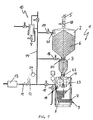
- the mill system 1 with the malt hull 2, the conditioning shaft 3 and the mill body 4 can from the raw material feed 5 a raw material silo, not shown, loaded with the raw material 6 become.
- the raw material 6 is in a crushing and mashing process processed within the mill system and the mash 7 from the Mash pump 8 above the mash extractor 9 in a not shown Pumped mash pot.
- the mill system is to be reloaded first drained the water castle 10, so that the inside of the plant contained air can escape at this point without pressure.
- the inert gas flows out the gas reservoir 13 into the pipe system 14.
- the Valves 15, 16 and 17 opened in ascending order and that Inert gas, which is heavier than air, fills the system from the lowest point starting in ascending order.
- the Air contained in the interior of the system through the open water lock 10 promoted from the inside of the plant to the outside.
- the inert gas Water castle 10 closed and the malt hull 2 via the raw material supply 5 filled with raw material.
- the sealing flap 18 is closed so that no air from can penetrate the outside of the system.
- Inert gas can enter the interior of the plant via the inlet openings 19, 20 and 21 promoted. Due to the additional volume shares of the imported Inert gas, an overpressure is built up inside the system prevents air from entering from the outside atmosphere.
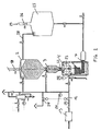
- Fig. 2 shows a second embodiment of a system according to the invention, which essentially corresponds to the first embodiment.
- the mash container 25 is indirectly connected to the gas supply via line 28 via the mill system.
- the mash container can also be filled with inert gas and, if necessary, flushed with inert gas.
- the mash container can be closed gas-tight with the flap 26.
- the mash vessel is vented through the outlet 29 with the flap 26 open.
- the system has an expanded internal pressure control.
- the pressure regulator 24 acts not only on the inlet valve 12 but also on the outlet valve 27. This means that not only negative pressures but also excess pressures in the system can be adjusted to a setpoint.
Landscapes
- Chemical & Material Sciences (AREA)
- Organic Chemistry (AREA)
- Engineering & Computer Science (AREA)
- General Health & Medical Sciences (AREA)
- Food Science & Technology (AREA)
- Biochemistry (AREA)
- Bioinformatics & Cheminformatics (AREA)
- General Engineering & Computer Science (AREA)
- Health & Medical Sciences (AREA)
- Genetics & Genomics (AREA)
- Life Sciences & Earth Sciences (AREA)
- Wood Science & Technology (AREA)
- Zoology (AREA)
- Disintegrating Or Milling (AREA)
- Crushing And Grinding (AREA)
- Agricultural Chemicals And Associated Chemicals (AREA)
- Processing Of Solid Wastes (AREA)
- Preparation Of Compounds By Using Micro-Organisms (AREA)
Description
- Fig. 1
- in schematischer Darstellung den Aufbau einer ersten Ausführungsform einer erfindungsgemäßen Anlage zur Schrotung und Maischeerzeugung.
- Fig. 2
- in schematischer Darstellung den Aufbau einer zweiten Ausführungsform einer erfindungsgemäßen Anlage zur Schrotung und Maischeerzeugung.
Claims (21)
- Verfahren zur Schrotung und Maischeerzeugung, bei dem der zu verarbeitende Rohstoff in einem Mühlensystem aufgebrochen und eingemaischt wird,
dadurch gekennzeichnet, daßvor der Befüllung des Mühlensystems (1) mit dem zu schrotenden Gut (6) das Mühlensystem (1) mit einem Inertgas befüllt wird, so daß der im Mühlensystem (1) befindliche Luftsauerstoff im wesentlichen verdrängt wird undnach der Befüllung des Mühlensystems (1) mit dem zu schrotenden Gut (6) das Mühlensystem (1) im wesentlichen gasdicht verschlossen wird. - Verfahren zur Schrotung und Maischeerzeugung nach Anspruch 1,
dadurch gekennzeichnet, daß während des Schrotungs- und Einmaischprozesses das Mühlensystem (1) zumindest bereichsweise mit Inertgas gespült wird, so daß während der Befüllung und anderweitig eindringender Luftsauerstoff verdrängt wird. - Verfahren zur Schrotung und Maischeerzeugung nach Anspruch 1 oder 2,
dadurch gekennzeichnet, daß in dem Mühlensystem (1) ein Inertgasüberdruck erzeugt wird. - Verfahren zur Schrotung und Maischeerzeugung nach einem der Ansprüche 1 bis 3,
dadurch gekennzeichnet, daß der Überdruck im Bereich von 2 - 100 Millibar liegt. - Verfahren zur Schrotung und Maischeerzeugung nach einem der Ansprüche 1 bis 4
dadurch gekennzeichnet, daß das Inertgas schwerer als Luft ist. - Verfahren zur Schrotung und Maischeerzeugung nach einem der Ansprüche 1 bis 5
dadurch gekennzeichnet, daß als Inertgas Kohlendioxid, Stickstoff oder ähnliche Gasgemische verwendet werden. - Verfahren zur Schrotung und Maischeerzeugung nach einem der Ansprüche 1 bis 6
dadurch gekennzeichnet, daß als Inertgas Stickstoff verwendet wird, der in einem vorhergehenden Gastrennverfahren aus Luft gewonnen wird. - Verfahren zur Schrotung und Maischeerzeugung nach einem der Ansprüche 1 bis 7
dadurch gekennzeichnet, daß zur Spülung des Mühlensystems (1) mit Inertgas im Inneren des Mühlensystems eine Inertgasströmung erzeugt wird, die entgegen der Förderrichtung des Rohstoffs gerichtet ist. - Verfahren zur Schrotung und Maischeerzeugung nach einem der Ansprüche 1 bis 8
dadurch gekennzeichnet, daß auch das dem Mühlensystem (1) nachgeschaltete Maischgefäß (25) gasdicht abgesperrt wird und anschließend mit Inertgas vorgespannt wird. - Verfahren zur Schrotung und Maischeerzeugung nach einem der Ansprüche 1 bis 9
dadurch gekennzeichnet, daß auch das dem Mühlensystem (1) nachgeschaltete Maischgefäß (25) mit Inertgas gespült wird. - Verfahren zur Schrotung und Maischeerzeugung nach einem der Ansprüche 1 bis 10,
dadurch gekennzeichnet, daß die Spülung des Mühlensystems (1) mit Inertgas in Abhängigkeit vom Restgehalt an Luftsauerstoff geregelt wird. - Anlage zur Schrotung und Maischeerzeugung mit einer Rohstoffzufuhr, einem Maischeabzug und Einrichtungen zur Schrotung und Einmaischung der Rohstoffe,
dadurch gekennzeichnet, daß die gesamte Anlage (1) im wesentlichen gasdicht absperrbar ist und über eine Gaszufuhr (11, 12, 13) mit Inertgas beaufschlagt werden kann. - Anlage zur Schrotung und Maischeerzeugung nach Anspruch 12,
dadurch gekennzeichnet, daß auch das Maischgefäß (25) gasdicht absperrbar ist und über eine Gaszufuhr (28) mit einem Inertgas beaufschlagt werden kann. - Anlage zur Schrotung und Maischeerzeugung nach Anspruch 12 oder 13,
dadurch gekennzeichnet, daß die Rohstoffzufuhr (5) mit einer im wesentlichen gasdichten Klappe (18) absperrbar ist. - Anlage zur Schrotung und Maischeerzeugung nach einem der Ansprüche 12 bis 14,
dadurch gekennzeichnet, daß im Malzrumpf (2) und/oder im Konditionierungsschacht (3) und /oder im Mühlenkörper (4) zumindest jeweils eine Einlaßöffnung (19, 20, 21) für die Inertgaszufuhr angeordnet ist. - Anlage zur Schrotung und Maischeerzeugung nach einem der Ansprüche 12 bis 15,
dadurch gekennzeichnet, daß die Einlaßöffnung (19) für die Inertgaszufuhr im Mühlenkörper (4) im Bereich zwischen Schrotmühle (23) und Maische (7) angeordnet ist. - Anlage zur Schrotung und Maischeerzeugung nach einem der Ansprüche 12 bis 16,
dadurch gekennzeichnet, daß im Malzrumpf (2) und/oder Konditionierungsschacht (3) und /oder im Mühlenkörper (4) Sonden zur Messung der Gasatmosphäre angeordnet sind. - Anlage zur Schrotung und Maischeerzeugung nach einem der Ansprüche 12 bis 17,
dadurch gekennzeichnet, daß in der Anlage zumindest ein Sicherungsventil (10) zu Sicherung gegen Über- und/oder Unterdruck angeordnet ist. - Anlage zur Schrotung und Maischeerzeugung nach einem der Ansprüche 12 bis 18,
dadurch gekennzeichnet, daß in der Anlage zumindest ein regelbares Einlaßventil (12) für die Inertgaszufuhr und zumindest ein regelbares Auslaßventil (27) angeordnet ist, die beide an eine Steuerung (24) zur Regelung des Anlageninnendrucks angeschlossen sind. - Anlage zur Schrotung und Maischeerzeugung nach einem der Ansprüche 12 bis 19,
dadurch gekennzeichnet, daß die Anlage über ein Wasserschloß (10) entlüftbar ist. - Anlage zur Schrotung und Maischeerzeugung nach einem der Ansprüche 12 bis 20,
dadurch gekennzeichnet, daß die Gaszufuhr an der Hauptzufuhr und/oder an den einzelnen Einlaßöffnungen (15, 16, 17) der verschiedenen Anlagenteile durch Ventile (11, 15, 16, 17) absperrbar ist.
Applications Claiming Priority (3)
| Application Number | Priority Date | Filing Date | Title |
|---|---|---|---|
| DE19740036 | 1997-09-11 | ||
| DE19740036A DE19740036C1 (de) | 1997-09-11 | 1997-09-11 | Gekapselte / luftfreie Schrotung und Maischeerzeugung |
| PCT/DE1998/002523 WO1999013047A2 (de) | 1997-09-11 | 1998-08-21 | Gekapselte/luftfreie schrotung und maischeerzeugung |
Publications (2)
| Publication Number | Publication Date |
|---|---|
| EP1012222A2 EP1012222A2 (de) | 2000-06-28 |
| EP1012222B1 true EP1012222B1 (de) | 2003-10-29 |
Family
ID=7842076
Family Applications (1)
| Application Number | Title | Priority Date | Filing Date |
|---|---|---|---|
| EP98952515A Expired - Lifetime EP1012222B1 (de) | 1997-09-11 | 1998-08-21 | Gekapselte/luftfreie schrotung und maischeerzeugung |
Country Status (7)
| Country | Link |
|---|---|
| US (1) | US6537596B1 (de) |
| EP (1) | EP1012222B1 (de) |
| AT (1) | ATE253108T1 (de) |
| AU (1) | AU1020499A (de) |
| DE (2) | DE19740036C1 (de) |
| WO (1) | WO1999013047A2 (de) |
| ZA (1) | ZA988275B (de) |
Families Citing this family (8)
| Publication number | Priority date | Publication date | Assignee | Title |
|---|---|---|---|---|
| IE980920A1 (en) * | 1997-11-07 | 1999-05-19 | Salviac Ltd | An embolic protection device |
| DE20107904U1 (de) | 2001-05-10 | 2001-08-16 | Anton Steinecker Maschinenfabrik GmbH, 85356 Freising | Schrotmühle mit Malzrumpf |
| ITFI20060263A1 (it) * | 2006-10-27 | 2008-04-28 | Saeco Ipr Ltd | Dispositivo emulsionatore per la produzione di latte schiumato e simili e relativo metodo |
| DE102012002345A1 (de) | 2012-02-08 | 2013-08-08 | Krones Ag | Naßschrotmühle für die Maischeherstellung bei der Biererzeugung |
| US9604226B2 (en) | 2012-05-01 | 2017-03-28 | Innovative Combustion Technologies, Inc. | Pulverizer mill protection system |
| WO2013166179A1 (en) | 2012-05-01 | 2013-11-07 | Innovative Combustion Technologies, Inc. | Pulverizer mill protection system |
| RU2700402C2 (ru) * | 2014-11-14 | 2019-09-16 | Конинклейке Филипс Н.В. | Способ и устройство для обработки кофейных зерен |
| JP2016116492A (ja) * | 2014-12-22 | 2016-06-30 | アサヒビール株式会社 | 麦芽の粉砕設備、麦芽の粉砕方法、飲料の製造方法、及び、飲料 |
Family Cites Families (8)
| Publication number | Priority date | Publication date | Assignee | Title |
|---|---|---|---|---|
| DE104160C (de) | ||||
| DE1070121B (de) | 1959-12-03 | |||
| GB907305A (en) * | 1957-07-24 | 1962-10-03 | Dixon Malt Company Ltd | Improvements in or relating to the malting of barley and other cereals |
| FR2506324A1 (fr) | 1981-05-22 | 1982-11-26 | Nordon & Cie Sa | Procede et installation de preparation d'un mout de brasserie |
| JP2851663B2 (ja) * | 1989-12-26 | 1999-01-27 | 株式会社佐竹製作所 | 精麦方法及び該方法を用いた製粉前処理方法 |
| DE4238069C1 (de) | 1992-11-11 | 1994-06-30 | Steinecker Anton Entwicklung | Verfahren zum kontinuierlichen Läutern von Maische unter Verwendung von Läuterbottichschrot |
| RU2054467C1 (ru) * | 1992-12-03 | 1996-02-20 | Акционерное общество закрытого типа - фирма "Тверь-пиво" ЛТД | Способ приготовления сусла для светлого пива |
| US6076752A (en) * | 1998-06-01 | 2000-06-20 | Quality Botanical Ingredients, Inc. | Method and apparatus for inert gas purging/temperature control for pulverizing/grinding system |
-
1997
- 1997-09-11 DE DE19740036A patent/DE19740036C1/de not_active Revoked
-
1998
- 1998-08-21 AU AU10204/99A patent/AU1020499A/en not_active Abandoned
- 1998-08-21 DE DE59810038T patent/DE59810038D1/de not_active Expired - Lifetime
- 1998-08-21 AT AT98952515T patent/ATE253108T1/de not_active IP Right Cessation
- 1998-08-21 US US09/486,014 patent/US6537596B1/en not_active Expired - Fee Related
- 1998-08-21 EP EP98952515A patent/EP1012222B1/de not_active Expired - Lifetime
- 1998-08-21 WO PCT/DE1998/002523 patent/WO1999013047A2/de not_active Ceased
- 1998-09-10 ZA ZA988275A patent/ZA988275B/xx unknown
Also Published As
| Publication number | Publication date |
|---|---|
| EP1012222A2 (de) | 2000-06-28 |
| ATE253108T1 (de) | 2003-11-15 |
| WO1999013047A2 (de) | 1999-03-18 |
| DE19740036C1 (de) | 1998-11-12 |
| WO1999013047A3 (de) | 1999-05-27 |
| DE59810038D1 (de) | 2003-12-04 |
| US6537596B1 (en) | 2003-03-25 |
| AU1020499A (en) | 1999-03-29 |
| ZA988275B (en) | 1999-03-23 |
Similar Documents
| Publication | Publication Date | Title |
|---|---|---|
| DE2036184C3 (de) | Schutzgaseinrichtung für flüssigen Brennstoff in Luftfahrzeugen | |
| DE1803190C3 (de) | Verfahren und Vorrichtung zum Entgasen von frisch geröstetem Kaffee | |
| DE3431107A1 (de) | Verfahren und vorrichtung zum fuellen von flaschen o.dgl. | |
| DE19740036C1 (de) | Gekapselte / luftfreie Schrotung und Maischeerzeugung | |
| EP3956045B1 (de) | Verfahren und vorrichtung zur industriellen herstellung eines extraktes durch fest-flüssig-extraktion | |
| DE60214174T2 (de) | Verfahren und anlage zur erzeugung von elektrischer energie durch eine gasturbine, die mit einer luftzerlegungsanlage versehen ist | |
| DE2652344C2 (de) | Gerät für den pneumatischen Transport von pulverförmigen oder granulierten Stoffen | |
| DE3026019A1 (de) | Verfahren zur gewinnung von gichtgas aus einem hochofen und vorrichtung zur durchfuehrung des verfahrens | |
| EP3966154A1 (de) | Maschine und verfahren zum füllen von behältern mit einem flüssigen füllgut | |
| DE60307504T2 (de) | Verfahren und vorrichtung zum steuern des füllvorgangs einer flüssigkeit in einen behälter | |
| DE4342142C2 (de) | Vorrichtung zum Füllen von Flaschen oder dergl. Behälter mit einem flüssigen Füllgut | |
| DE29724660U1 (de) | Anlage zur Schrotung und Maischeerzeugung | |
| DE10251634B4 (de) | Verfahren zum Begasen von Schüttgut in einem Schüttgut-Silo und Anlage zur Durchführung des Verfahrens | |
| DE1692739B2 (de) | ||
| DE4201698A1 (de) | Verfahren zum fuellen von flaschen o. dgl. behaelter mit einem fluessigen fuellgut sowie vorrichtung zum durchfuehren dieses verfahrens | |
| DE3021083A1 (de) | Verfahren zum zerkleinern von stoffgemischen, insbesondere aus pflanzenprodukten, sowie vorrichtung zur durchfuehrung des verfahrens | |
| DE2619993B2 (de) | Verfahren zur Entnahme von Schüttgut aus einem bodenbelüfteten Silo sowie Entnahmevorrichtung zur Durchführung des Verfahrens | |
| DE102018127513A1 (de) | Verfahren sowie Füllsystem zum Befüllen von Behältern | |
| DE202020107037U1 (de) | CO2-Gaszufuhr mittels eines Aquariendruckgasbehälters mit einem Nährsubstrat | |
| DE1140863B (de) | Entnahmeverfahren fuer Schuettgut aus einem Druckbehaelter | |
| DE3543697C2 (de) | ||
| EP3997248B1 (de) | Abdichtung eines reduktionsaggregats | |
| DE19838778C2 (de) | Mehrstufige Wasseraufbereitungsanlage mit Druckwasserüberleitung | |
| DE2712899C3 (de) | Vorrichtung zur Regelung der Teilverbrennung von Reaktionsgasen aus Stahlkonvertern und Verfahren unter Verwendung der Vorrichtung | |
| DE2522088A1 (de) | Vorrichtung zur mischung von granulaten durch einblasen eines gasfoermigen mediums, insbesondere von druckluft in einen behaelter |
Legal Events
| Date | Code | Title | Description |
|---|---|---|---|
| PUAI | Public reference made under article 153(3) epc to a published international application that has entered the european phase |
Free format text: ORIGINAL CODE: 0009012 |
|
| 17P | Request for examination filed |
Effective date: 20000316 |
|
| AK | Designated contracting states |
Kind code of ref document: A2 Designated state(s): AT DE DK ES GB |
|
| GRAH | Despatch of communication of intention to grant a patent |
Free format text: ORIGINAL CODE: EPIDOS IGRA |
|
| GRAH | Despatch of communication of intention to grant a patent |
Free format text: ORIGINAL CODE: EPIDOS IGRA |
|
| GRAA | (expected) grant |
Free format text: ORIGINAL CODE: 0009210 |
|
| AK | Designated contracting states |
Kind code of ref document: B1 Designated state(s): AT DE DK ES GB |
|
| PG25 | Lapsed in a contracting state [announced via postgrant information from national office to epo] |
Ref country code: GB Free format text: LAPSE BECAUSE OF FAILURE TO SUBMIT A TRANSLATION OF THE DESCRIPTION OR TO PAY THE FEE WITHIN THE PRESCRIBED TIME-LIMIT Effective date: 20031029 |
|
| REG | Reference to a national code |
Ref country code: GB Ref legal event code: FG4D Free format text: NOT ENGLISH |
|
| REF | Corresponds to: |
Ref document number: 59810038 Country of ref document: DE Date of ref document: 20031204 Kind code of ref document: P |
|
| PG25 | Lapsed in a contracting state [announced via postgrant information from national office to epo] |
Ref country code: DK Free format text: LAPSE BECAUSE OF FAILURE TO SUBMIT A TRANSLATION OF THE DESCRIPTION OR TO PAY THE FEE WITHIN THE PRESCRIBED TIME-LIMIT Effective date: 20040129 |
|
| PG25 | Lapsed in a contracting state [announced via postgrant information from national office to epo] |
Ref country code: ES Free format text: LAPSE BECAUSE OF FAILURE TO SUBMIT A TRANSLATION OF THE DESCRIPTION OR TO PAY THE FEE WITHIN THE PRESCRIBED TIME-LIMIT Effective date: 20040209 |
|
| GBV | Gb: ep patent (uk) treated as always having been void in accordance with gb section 77(7)/1977 [no translation filed] |
Effective date: 20031029 |
|
| PG25 | Lapsed in a contracting state [announced via postgrant information from national office to epo] |
Ref country code: AT Free format text: LAPSE BECAUSE OF NON-PAYMENT OF DUE FEES Effective date: 20040821 |
|
| PLBE | No opposition filed within time limit |
Free format text: ORIGINAL CODE: 0009261 |
|
| STAA | Information on the status of an ep patent application or granted ep patent |
Free format text: STATUS: NO OPPOSITION FILED WITHIN TIME LIMIT |
|
| 26N | No opposition filed |
Effective date: 20040730 |
|
| PGFP | Annual fee paid to national office [announced via postgrant information from national office to epo] |
Ref country code: DE Payment date: 20141022 Year of fee payment: 17 |
|
| REG | Reference to a national code |
Ref country code: DE Ref legal event code: R119 Ref document number: 59810038 Country of ref document: DE |
|
| PG25 | Lapsed in a contracting state [announced via postgrant information from national office to epo] |
Ref country code: DE Free format text: LAPSE BECAUSE OF NON-PAYMENT OF DUE FEES Effective date: 20160301 |