EP1012006B1 - Öffnungsvorrichtung für den gasdruckbehälter eines airbags - Google Patents
Öffnungsvorrichtung für den gasdruckbehälter eines airbags Download PDFInfo
- Publication number
- EP1012006B1 EP1012006B1 EP19980948949 EP98948949A EP1012006B1 EP 1012006 B1 EP1012006 B1 EP 1012006B1 EP 19980948949 EP19980948949 EP 19980948949 EP 98948949 A EP98948949 A EP 98948949A EP 1012006 B1 EP1012006 B1 EP 1012006B1
- Authority
- EP
- European Patent Office
- Prior art keywords
- gas pressure
- opening
- sealing element
- airbag
- housing
- Prior art date
- Legal status (The legal status is an assumption and is not a legal conclusion. Google has not performed a legal analysis and makes no representation as to the accuracy of the status listed.)
- Expired - Lifetime
Links
- 238000007789 sealing Methods 0.000 claims abstract description 33
- 239000007789 gas Substances 0.000 claims description 60
- 239000001307 helium Substances 0.000 claims description 8
- 229910052734 helium Inorganic materials 0.000 claims description 8
- SWQJXJOGLNCZEY-UHFFFAOYSA-N helium atom Chemical compound [He] SWQJXJOGLNCZEY-UHFFFAOYSA-N 0.000 claims description 8
- 230000001960 triggered effect Effects 0.000 claims description 3
- 238000011144 upstream manufacturing Methods 0.000 claims description 3
- 239000011261 inert gas Substances 0.000 claims description 2
- 239000010408 film Substances 0.000 description 5
- 239000000203 mixture Substances 0.000 description 3
- 230000003068 static effect Effects 0.000 description 3
- XKRFYHLGVUSROY-UHFFFAOYSA-N Argon Chemical compound [Ar] XKRFYHLGVUSROY-UHFFFAOYSA-N 0.000 description 2
- IJGRMHOSHXDMSA-UHFFFAOYSA-N Atomic nitrogen Chemical compound N#N IJGRMHOSHXDMSA-UHFFFAOYSA-N 0.000 description 2
- 238000010276 construction Methods 0.000 description 2
- 239000002360 explosive Substances 0.000 description 2
- 238000004519 manufacturing process Methods 0.000 description 2
- 239000000463 material Substances 0.000 description 2
- 229910052756 noble gas Inorganic materials 0.000 description 2
- 229910052786 argon Inorganic materials 0.000 description 1
- 238000004880 explosion Methods 0.000 description 1
- 230000002349 favourable effect Effects 0.000 description 1
- 238000007373 indentation Methods 0.000 description 1
- 239000012528 membrane Substances 0.000 description 1
- 230000007935 neutral effect Effects 0.000 description 1
- 229910052757 nitrogen Inorganic materials 0.000 description 1
- 239000010409 thin film Substances 0.000 description 1
Images

Classifications
-
- B—PERFORMING OPERATIONS; TRANSPORTING
- B60—VEHICLES IN GENERAL
- B60R—VEHICLES, VEHICLE FITTINGS, OR VEHICLE PARTS, NOT OTHERWISE PROVIDED FOR
- B60R21/00—Arrangements or fittings on vehicles for protecting or preventing injuries to occupants or pedestrians in case of accidents or other traffic risks
- B60R21/02—Occupant safety arrangements or fittings, e.g. crash pads
- B60R21/16—Inflatable occupant restraints or confinements designed to inflate upon impact or impending impact, e.g. air bags
- B60R21/26—Inflatable occupant restraints or confinements designed to inflate upon impact or impending impact, e.g. air bags characterised by the inflation fluid source or means to control inflation fluid flow
- B60R21/268—Inflatable occupant restraints or confinements designed to inflate upon impact or impending impact, e.g. air bags characterised by the inflation fluid source or means to control inflation fluid flow using instantaneous release of stored pressurised gas
-
- F—MECHANICAL ENGINEERING; LIGHTING; HEATING; WEAPONS; BLASTING
- F17—STORING OR DISTRIBUTING GASES OR LIQUIDS
- F17C—VESSELS FOR CONTAINING OR STORING COMPRESSED, LIQUEFIED OR SOLIDIFIED GASES; FIXED-CAPACITY GAS-HOLDERS; FILLING VESSELS WITH, OR DISCHARGING FROM VESSELS, COMPRESSED, LIQUEFIED, OR SOLIDIFIED GASES
- F17C7/00—Methods or apparatus for discharging liquefied, solidified, or compressed gases from pressure vessels, not covered by another subclass
-
- F—MECHANICAL ENGINEERING; LIGHTING; HEATING; WEAPONS; BLASTING
- F17—STORING OR DISTRIBUTING GASES OR LIQUIDS
- F17C—VESSELS FOR CONTAINING OR STORING COMPRESSED, LIQUEFIED OR SOLIDIFIED GASES; FIXED-CAPACITY GAS-HOLDERS; FILLING VESSELS WITH, OR DISCHARGING FROM VESSELS, COMPRESSED, LIQUEFIED, OR SOLIDIFIED GASES
- F17C2201/00—Vessel construction, in particular geometry, arrangement or size
- F17C2201/01—Shape
- F17C2201/0104—Shape cylindrical
-
- F—MECHANICAL ENGINEERING; LIGHTING; HEATING; WEAPONS; BLASTING
- F17—STORING OR DISTRIBUTING GASES OR LIQUIDS
- F17C—VESSELS FOR CONTAINING OR STORING COMPRESSED, LIQUEFIED OR SOLIDIFIED GASES; FIXED-CAPACITY GAS-HOLDERS; FILLING VESSELS WITH, OR DISCHARGING FROM VESSELS, COMPRESSED, LIQUEFIED, OR SOLIDIFIED GASES
- F17C2205/00—Vessel construction, in particular mounting arrangements, attachments or identifications means
- F17C2205/03—Fluid connections, filters, valves, closure means or other attachments
- F17C2205/0302—Fittings, valves, filters, or components in connection with the gas storage device
- F17C2205/0323—Valves
- F17C2205/0332—Safety valves or pressure relief valves
-
- F—MECHANICAL ENGINEERING; LIGHTING; HEATING; WEAPONS; BLASTING
- F17—STORING OR DISTRIBUTING GASES OR LIQUIDS
- F17C—VESSELS FOR CONTAINING OR STORING COMPRESSED, LIQUEFIED OR SOLIDIFIED GASES; FIXED-CAPACITY GAS-HOLDERS; FILLING VESSELS WITH, OR DISCHARGING FROM VESSELS, COMPRESSED, LIQUEFIED, OR SOLIDIFIED GASES
- F17C2221/00—Handled fluid, in particular type of fluid
- F17C2221/01—Pure fluids
- F17C2221/016—Noble gases (Ar, Kr, Xe)
- F17C2221/017—Helium
-
- F—MECHANICAL ENGINEERING; LIGHTING; HEATING; WEAPONS; BLASTING
- F17—STORING OR DISTRIBUTING GASES OR LIQUIDS
- F17C—VESSELS FOR CONTAINING OR STORING COMPRESSED, LIQUEFIED OR SOLIDIFIED GASES; FIXED-CAPACITY GAS-HOLDERS; FILLING VESSELS WITH, OR DISCHARGING FROM VESSELS, COMPRESSED, LIQUEFIED, OR SOLIDIFIED GASES
- F17C2223/00—Handled fluid before transfer, i.e. state of fluid when stored in the vessel or before transfer from the vessel
- F17C2223/01—Handled fluid before transfer, i.e. state of fluid when stored in the vessel or before transfer from the vessel characterised by the phase
- F17C2223/0107—Single phase
- F17C2223/0123—Single phase gaseous, e.g. CNG, GNC
-
- F—MECHANICAL ENGINEERING; LIGHTING; HEATING; WEAPONS; BLASTING
- F17—STORING OR DISTRIBUTING GASES OR LIQUIDS
- F17C—VESSELS FOR CONTAINING OR STORING COMPRESSED, LIQUEFIED OR SOLIDIFIED GASES; FIXED-CAPACITY GAS-HOLDERS; FILLING VESSELS WITH, OR DISCHARGING FROM VESSELS, COMPRESSED, LIQUEFIED, OR SOLIDIFIED GASES
- F17C2270/00—Applications
- F17C2270/01—Applications for fluid transport or storage
- F17C2270/0165—Applications for fluid transport or storage on the road
- F17C2270/0181—Airbags
-
- Y—GENERAL TAGGING OF NEW TECHNOLOGICAL DEVELOPMENTS; GENERAL TAGGING OF CROSS-SECTIONAL TECHNOLOGIES SPANNING OVER SEVERAL SECTIONS OF THE IPC; TECHNICAL SUBJECTS COVERED BY FORMER USPC CROSS-REFERENCE ART COLLECTIONS [XRACs] AND DIGESTS
- Y10—TECHNICAL SUBJECTS COVERED BY FORMER USPC
- Y10T—TECHNICAL SUBJECTS COVERED BY FORMER US CLASSIFICATION
- Y10T137/00—Fluid handling
- Y10T137/1624—Destructible or deformable element controlled
- Y10T137/1632—Destructible element
- Y10T137/1774—With counterbalancing element
Definitions
- the invention relates to an inflator for an airbag according to the preamble of claim 1.
- Such an inflator is known from DE 195 40 618 A1.
- the outflow opening of the pressure vessel is closed with a sealing element which is supported for supporting the gas forces via a pressure piece on a housing-fixed abutment.
- the pressure piece is assigned a pyrotechnic charge in the ignition of the abutment destroyed and thus the support of the sealing element is repealed.
- the sealing element is now destroyed solely by the gas pressure in the container and the airbag connected to the housing is inflated by the outflowing gas.
- the filled gas pressure vessels are manufactured by suppliers and sent to end users.
- the ready-to-ship gas pressure vessels contain ready opening devices, each with a pyrotechnic charge, which is why careful handling during manufacture, shipping and final assembly is necessary in order to avoid unintentional triggering of the opening device.
- the gas stored in the gas pressure vessel must be in a certain mixture to ensure rapid proper inflation of the air bag without mechanical damage.
- the invention has the object of developing a generic device such that a sudden opening of the airbag without mechanical damage is ensured by the inflation.
- a throttle is provided in the outflow direction of the gases in front of the outflow opening of the gas pressure vessel, wherein the opening cross section of the outflow opening is greater than that of the throttle. Between the throttle and the discharge opening, a pressure chamber is formed.
- the outflow opening can be made large in diameter, whereby the pressure prevailing in the gas pressure vessel and the pressure chamber gas pressure acts on a correspondingly large area and large opening forces available stand, which ensure an explosive opening of the pressure vessel when the pressure piece is omitted.
- the outflow velocity of the gas is determined by the throttle, which is selected according to the gas filling and permanently installed during the manufacture of the container.
- the pressure vessel is predominantly with a noble gas, in particular helium or a helium mixture, filled, wherein the outflow velocity of the gas from the outflow opening is structurally predetermined by the upstream throttle.
- a noble gas in particular helium or a helium mixture
- Helium has a low temperature dependence and due to the lower molecular weight, a high flow velocity, which is adaptable with the throttle to the airbag to be filled.
- the triggering device is designed as a separate housing, independently mountable unit. Since the support of the sealing element is independent of the triggering device stable, the pre-assembly of the opening device can be done with the gas pressure vessel without triggering device.
- the housing remains expediently open on opposite sides, so that when an unintentional opening of the sealing element, the pressurized gas flows out on opposite sides of the same opening area and thus only thrust neutral reaction forces occur. Therefore, the gas pressure vessel will hardly or not move, so that in the pre-assembly, shipping and final assembly without additional effort high security is achieved.
- the triggering device is pre-assembled separately from the opening device and the gas pressure vessel. Only in the final assembly, the opening device for the gas pressure vessel is provided with the triggering device and made the overall arrangement ready for operation. But then the gas pressure vessel is firmly mounted, so that the thrust forces occurring the outflowing gases are intercepted.
- the housing is formed from a connected to the pressure vessel body with open end faces, which can be closed by end plates.
- the base body for shipping with provisional end plates be closed both have a same large outflow opening. Damage to the opening device in the housing can be safely avoided.
- the tripping device mounted in a face plate is attached to the base body, wherein the tripping device opposite end plate can have the necessary outflow openings for the filling gas of the airbag; Suitably, the airbag is attached to this end plate.
- the open edge of the end face of the base body engages in a receiving groove of the end plate.
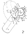
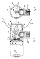
- the gas pressure vessel 1 shown in Fig. 1 is used to inflate an airbag 2, as it e.g. used in motor vehicles.
- FIGS. 2 and 3 a housing 4, which is firmly connected to the container 1, adjoins the central outflow opening 3 of the pressure vessel 1.
- the discharge opening 3 is preferably coaxial with the central longitudinal axis 48 of the container 1.
- FIGS. 1, 2 and 7 A detailed construction of the housing 4 is shown in FIGS. 1, 2 and 7, while FIGS. 3 to 6 show the housing 4 only schematically and FIGS. 8 and 9 show an alternative housing.
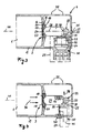
- the housing 4 consists - as shown in particular in FIG. 2 - of a hollow base body 5 with opposite, open end faces 6 and 7, by end plates 8 and 9 to be closed.
- the end plates 8 and 9 are formed larger than the end faces 6 and 7, so that the end plates 8 and 9 project beyond the base housing 5.
- through holes 11 are provided for the arrangement of tie rods 12.
- the face plates 8 and 9 are suitably the same size, so that the through holes 11 of the opposite end plates 8 and 9 are congruent to each other and allow the arrangement of the respective tie rods 12.
- the outflow opening 3 of the gas pressure vessel 1 discharges approximately centrally into the housing 4 or its basic body 5, which in the exemplary embodiment shown is square in cross-section.
- Other cross-sectional shapes of the basic housing 5 may be advantageous ( Figure 8).
- the housing 4 or the base housing 5 is open on opposite sides 6, 7.
- the open sides 6, 7 preferably have the same area; the median perpendicular of each end face 6, 7 is coaxially with the longitudinal central axis 45 of the base body 5 and the housing 4.
- the central longitudinal axis 48 of the pressure vessel 1 intersects the longitudinal central axis 45 of the housing 4 at right angles.
- the outflow opening 3 is closed by a sealing element 15, which is formed in the embodiment shown as a thin film and is mounted on the side facing away from the housing 4 of the outflow opening 3 in the pressure vessel 1.
- the sealing element 15 in the region of the film edge 16 is pressure-tightly connected to the container housing 17.
- the sealing element 15 rests on the side facing the housing 4 on a support disk 18, which is placed in the outflow opening 3.
- the support plate 18 is with radial play to the edge 19 of the discharge opening 3, whereby an annular gap 20 is formed, which is closed by the sealing element 15 on the container side.
- This annular gap 20 forms a pressure relief valve; the design of the annular gap in conjunction with the material of the sealing element 15 is such that at a predeterminable limit pressure, the sealing element 15 breaks in the region of the annular gap, so that the excess pressure is controlled blown off via the annular gap 20, without the outflow opening 3 itself is open , 8 and 9 show a gas pressure vessel without an annular gap.
- the support disk 18 is supported via a pressure piece 21 on a housing-fixed abutment 22, so that the forces acting through the gas pressure in the container 1 on the sealing element 15 opening forces are safely intercepted.
- the pressure piece 21 is in this case with a spherical head end 23 in a corresponding concave bearing 24 of the support plate 18, while the other end 25 of the pressure piece 21 has a slightly concave locking recess 26 with which the pressure piece slightly latching abuts a the abutment 22 forming bolt 27 ,
- the bolt 27 is held in opposite holes 47 of the base body 5.
- the longitudinal axis 28 of the pressure piece 21 is perpendicular to the support plate 18 and the sealing element 15, preferably passes through the axis of the bolt 27 and is coaxially to the central longitudinal axis 48 of the container first
- a triggering device 30 is arranged, which - as shown in FIG. 2 - is mounted in a front plate 9 of the housing.
- the triggering device 30 forms together with the front plate 9 a separate from the housing 4, independently mountable unit 29th
- the triggering device 30 consists essentially of an actuating piston 31 which is displaceably guided transversely to the longitudinal axis 28 in a corresponding cylinder 32, wherein in the cylinder 32, a pyrotechnic charge 33 is arranged, which is to ignite electrically in a known manner.
- the actuating piston 31 is located near the abutment pin 27 in the region of the end 25 on the pressure piece 21, wherein the longitudinal axis 34 of the cylinder 32 is preferably at right angles to the longitudinal axis 28 of the pressure piece 21.
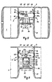
- Figs. 3 to 6 show various embodiments of an opening device as general background information to the present invention.
- the support of the sealing element 15 via the support plate 18, the pressure piece 21 and the abutment 22 is independent of the triggering device 30 stable, including the latching recess 26 contributes.
- the gas pressure vessel 1 can therefore be preassembled and filled without operation of the deployment device 30, without the pyrotechnic ignition charge 33 being arranged. This has advantages in pre-assembly, shipping and final assembly. Only in the final assembly is the end plate 9 with the triggering device 30, which contains the pyrotechnic charge 33, fixed in the manner already described on the base housing 5, wherein arranged on the other end face 6 end plate 8 discharge openings 35, over which the preferred the front plate 8 attached airbag 2 is inflated.
- a purely electrically or thermoelectrically operating triggering device 30 is provided.
- the bolt 27 facing the end 25 of the pressure piece 21 is chamfered, so that the forces acting in the direction of arrow 36 on the pressure member 21 due to the inclined plane 37 at the end 25 of the pressure piece 21, a resultant force 38th occurs, which endeavors to release the pressure piece 21 from the abutment 22.
- the resulting force 38 is transmitted through an electrically conductive, mechanically load-bearing wire 39 intercepted, wherein the wire 39 is fixed to the one end via an insulating piece 40 in the pressure piece 21 and the other end via a further insulating piece 40 in the housing 4.
- the electrical tripping device 30 in accordance with the pyrotechnic tripping device 30 in FIG. 3 as a separate unit which can be mounted separately from the housing.
- the embodiment of FIG. 5 corresponds to the principle of the triggering device 30 of the electrical tripping device described in Fig. 4, which is why the same reference numerals are used for the same parts.
- the compressed gas container 1 is formed in the embodiment of FIG. 5 of two round, separate individual containers, in the center of the housing 4 is provided.
- the toroidal ring has two outflow openings 3 and 3a, wherein the outflow opening 3a is made smaller than the outflow opening 3.
- the arranged sealing elements 15 and 15a are in the same way via a support plate 18 and 18a and a pressure piece 21 or 21a at a common Abutment 22 supported. For each support, a separate holding wire 39 is provided, so that the outflow openings 3, 3a can be opened with a time offset to each other.
- the first outflow opening 3a of the one container is advantageously opened to then - with a staggered time - to open the larger outflow opening 3 of the other container for final inflation of the airbag.
- the two pressure pieces 21 and 21a are arranged on a common abutment 22, wherein without the arrangement of the pyrotechnic release device 30, the support of the respective sealing elements 15 and 15a is stable according to a toggle lever arrangement.
- the ends 25 and 25a of the plungers 21, 21a have latching recesses 26, 26a, as described in connection with the embodiment of FIG. 3.
- the abutment 22a is slidably held in a longitudinal slot 42 of the housing 4, wherein the actuating piston 31 of the pyrotechnic triggering device 30 engages the abutment 22a.
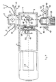
- the embodiment according to the invention of Figure 7 corresponds in construction to that of Fig. 2. like parts bear like reference numerals.
- the body 4 forming the main body 5 is welded to the neck of the pressure vessel 1 and has opposing open end faces 6 and 7.
- the front plate 9 has centering pins 42.
- the support plate 18 is with only a small clearance in the outflow opening 3, so that a little pressure-stable film is used as a sealing element 15. Due to the small play of the support disk 18 in the opening, the film is supported over substantially the entire opening cross section of the outflow opening.
- the opening cross-section for example, the diameter of the outflow opening 3, is chosen so large that the gas pressure causes a large opening force on the support plate 18, so that in the event of triggering when pushing the pressure piece 21 an immediate, explosive opening of the discharge opening 3 is ensured.
- the pressure vessel is advantageously filled with a helium mixture, but in particular predominantly with helium or another suitable noble gas, which has a low temperature dependence and a high blow-off speed with the same storage pressure, which can be advantageously used for very short inflation times of the airbag.
- a throttle 49 is provided in the pressure vessel 1 in the outflow direction of the gas upstream of the outflow opening 3.
- the throttle 49 is designed as a pinhole, wherein the throttle plate 47 is welded at its outer edge in approximately, preferably completely, gas-tight with the container wall.
- the throttle opening 50 is expediently symmetrical to the central longitudinal axis 48 of the container housing 17 and in particular in alignment with the blow-out opening 3.
- the opening cross-section of the outflow opening 3 is larger, in particular by a multiple greater than the opening cross-section of the throttle opening 50.
- a ratio of about 3: 1 is advantageous.
- the throttle plate 47 is approximately in the range of indentation to the bottleneck at a distance d approximately parallel to the sealing element 15 and the support plate 18 so that in the bottleneck between the sealing element 15 and the throttle plate 48, a pressure chamber 46 is formed in which the same static pressure prevails As in the rest of the container housing 17. After opening the discharge opening, the pressure drops and is then determined by the flowing over the throttle opening 50 Gases.
- the distance d corresponds to approximately half the diameter D of the throttle opening 50.
- the outlet openings 35 having end plate 8 is provided with a cup-like depression, which protrudes as a dome in the airbag and its secure attachment allows.
- the bottleneck with the throttle plate 47 and the outflow opening 3 and the sealing element 15 together with the base housing 5 is designed as a pipe section which is welded at one open end to a pressure vessel 1 and at the other open end face is closed with a screw-on or screw cap 8a, which has the outflow openings 35 and protrudes like a dome in the airbag.
- the triggering device 30 is screwed as a component in the cylindrical wall of the pipe section transverse to the central longitudinal axis 48 (FIG. 9), whereby the opening device is complete.
Landscapes
- Engineering & Computer Science (AREA)
- Mechanical Engineering (AREA)
- General Engineering & Computer Science (AREA)
- Physics & Mathematics (AREA)
- Fluid Mechanics (AREA)
- Air Bags (AREA)
- Safety Valves (AREA)
Applications Claiming Priority (3)
| Application Number | Priority Date | Filing Date | Title |
|---|---|---|---|
| DE19739375A DE19739375B4 (de) | 1997-09-09 | 1997-09-09 | Öffnungsvorrichtung für einen Gasdruckbehälter eines Airbags |
| DE19739375 | 1997-09-09 | ||
| PCT/EP1998/005755 WO1999012775A1 (de) | 1997-09-09 | 1998-09-09 | Öffnungsvorrichtung für den gasdruckbehälter eines airbags |
Publications (2)
| Publication Number | Publication Date |
|---|---|
| EP1012006A1 EP1012006A1 (de) | 2000-06-28 |
| EP1012006B1 true EP1012006B1 (de) | 2006-04-26 |
Family
ID=7841654
Family Applications (1)
| Application Number | Title | Priority Date | Filing Date |
|---|---|---|---|
| EP19980948949 Expired - Lifetime EP1012006B1 (de) | 1997-09-09 | 1998-09-09 | Öffnungsvorrichtung für den gasdruckbehälter eines airbags |
Country Status (8)
| Country | Link |
|---|---|
| US (1) | US6247725B1 (pt) |
| EP (1) | EP1012006B1 (pt) |
| JP (1) | JP3665740B2 (pt) |
| AT (1) | ATE324299T1 (pt) |
| DE (2) | DE19739375B4 (pt) |
| ES (1) | ES2263219T3 (pt) |
| PT (1) | PT1012006E (pt) |
| WO (1) | WO1999012775A1 (pt) |
Cited By (1)
| Publication number | Priority date | Publication date | Assignee | Title |
|---|---|---|---|---|
| CN103732454A (zh) * | 2011-08-03 | 2014-04-16 | 罗伯特·博世有限公司 | 用于为激活气囊提供冷气体的冷气体发生器以及用于为气囊激活提供冷气体的方法 |
Families Citing this family (48)
| Publication number | Priority date | Publication date | Assignee | Title |
|---|---|---|---|---|
| DE10031749A1 (de) * | 2000-06-29 | 2002-01-10 | Welz Industrieprodukte Gmbh | Kaltgasgenerator |
| US20030137135A1 (en) * | 2000-06-29 | 2003-07-24 | Welz Industrieprodukte Gmbh | Cold Gas Generator |
| DE10031751A1 (de) * | 2000-06-29 | 2002-01-10 | Welz Industrieprodukte Gmbh | Kaltgasgenerator |
| DE10031750A1 (de) * | 2000-06-29 | 2002-01-10 | Welz Industrieprodukte Gmbh | Kaltgasgenerator für ein Airbag-System |
| FR2811624B1 (fr) * | 2000-07-12 | 2002-12-06 | Alstom | Dispositif d'echappement d'un element gonflable et dispositif de protection d'un vehicule contre le choc equipe d'un tel dispositif d'echappement |
| DE20016041U1 (de) | 2000-09-15 | 2002-02-21 | Breed Automotive Technology, Inc., Lakeland, Fla. | Vorrichtung zum Antrieb eines Kolbens zum Freisetzen eines Füllgases aus einem Gasgenerator, insbesondere Gasspeicher |
| JP2002172995A (ja) * | 2000-09-28 | 2002-06-18 | Takata Corp | ストアーガスインフレータ |
| DE10063093B4 (de) * | 2000-12-18 | 2005-10-13 | Key Safety Systems, Inc., Sterling Heights | Vorrichtung zum Füllen eines Airbags |
| DE10103974B4 (de) * | 2001-01-30 | 2006-03-09 | Key Safety Systems, Inc., Sterling Heights | Vorrichtung zur Prüfung des Fülldruckes eines Airbag-Gasspeichers |
| JP4864251B2 (ja) * | 2001-02-26 | 2012-02-01 | 株式会社ダイセル | インフレータ |
| GB2373310B (en) * | 2001-03-15 | 2005-02-02 | Autoliv Dev | Improvements in or relating to an inflator |
| DE20104433U1 (de) | 2001-03-15 | 2001-06-13 | Breed Automotive Technology, Inc., Lakeland, Fla. | Vorrichtung zum Befüllen eines Airbags |
| DE10112558B4 (de) * | 2001-03-15 | 2006-04-20 | Key Safety Systems, Inc., Sterling Heights | Vorrichtung zum Füllen eines Airbags |
| US6914742B1 (en) | 2001-06-22 | 2005-07-05 | Seagate Technology Llc | Data storage assembly with robust servo writing methodology |
| US7332330B2 (en) * | 2001-09-11 | 2008-02-19 | Renamed Biologics, Inc. | Device for maintaining vascularization near an implant |
| US6554315B2 (en) * | 2001-09-27 | 2003-04-29 | Trw Inc. | Inflatable vehicle occupant protection device |
| DE10297387T5 (de) | 2001-10-30 | 2005-02-24 | Seagate Technology Llc, Scotts Valley | Ein Gas geringer Dichte anwendender Plattenlaufwerk-Servo-Spurschreiber |
| DE10158222B4 (de) * | 2001-11-16 | 2013-07-18 | TAKATA Aktiengesellschaft | Auslösevorrichtung für Sicherheitssystem |
| JP4063039B2 (ja) * | 2001-12-10 | 2008-03-19 | タカタ株式会社 | インフレータアッセンブリ及びエアベルト |
| US6629703B2 (en) * | 2001-12-14 | 2003-10-07 | Breed Automotive Technology, Inc. | Opening device for a cold gas inflator |
| DE10202552B4 (de) * | 2002-01-24 | 2016-04-21 | Volkswagen Ag | Ventilanordnung für einen Druckbehälter eines Airbag-Gasgenerators |
| DE60207448T2 (de) * | 2002-04-10 | 2006-07-27 | Dalphi-Metal España S.A. | Druckgasbehälter |
| US6726243B2 (en) * | 2002-05-31 | 2004-04-27 | Autoliv Asp, Inc. | Tuning the performance of compressed gas-containing inflators |
| US6908105B2 (en) * | 2002-06-26 | 2005-06-21 | Daicel Chemical Industries, Ltd. | Gas generator for air bag |
| US7175198B2 (en) | 2002-08-20 | 2007-02-13 | Daicel Chemical Industries, Ltd. | Inflator |
| JP2004074947A (ja) * | 2002-08-20 | 2004-03-11 | Daicel Chem Ind Ltd | インフレータ |
| US7293797B2 (en) | 2002-10-07 | 2007-11-13 | Daicel Chemical Industries, Ltd. | Inflator |
| JP4067929B2 (ja) * | 2002-10-07 | 2008-03-26 | ダイセル化学工業株式会社 | インフレータ |
| WO2004045923A1 (en) * | 2002-11-14 | 2004-06-03 | Automotive Systems Laboratory, Inc. | Pressurized gas release mechanism |
| AT6624U1 (de) * | 2002-11-29 | 2004-01-26 | Isi Airbag Gmbh | Kaltgasgenerator |
| US6857657B2 (en) | 2003-04-07 | 2005-02-22 | Key Safety Systems, Inc. | Inflator having a support member capable of sliding to open the pressure vessel |
| DE10318888B3 (de) * | 2003-04-17 | 2004-10-28 | Takata-Petri (Ulm) Gmbh | Gasgenerator für ein Insassenschutzsystem eines Fahrzeugs |
| DE20306818U1 (de) * | 2003-05-02 | 2003-09-11 | TRW Occupant Restraint Systems GmbH & Co. KG, 73553 Alfdorf | Gassack-Modul |
| DE10333895A1 (de) * | 2003-07-22 | 2005-02-17 | Petri-Dn Gmbh Inflator Systems | Gasgenerator |
| DE10346372A1 (de) * | 2003-09-29 | 2005-05-25 | Petri-Dn Gmbh Inflator Systems | Gasgenerator für ein Airbagmodul |
| DE102004026436A1 (de) * | 2004-05-27 | 2005-12-22 | Werner Herrmann | Mechanische Sperr- und Auslösevorrichtung |
| US7316417B2 (en) * | 2004-06-30 | 2008-01-08 | Autoliv Asp, Inc. | Inflator with internally mounted initiator |
| GB2417066B (en) * | 2004-08-13 | 2006-12-06 | Autoliv Dev | Improvements in or relating to an inflator for an air-bag |
| EP1800972B1 (en) | 2005-12-20 | 2008-10-29 | Key Safety Systems, Inc. | Inflator having an improved closure cap |
| ATE412560T1 (de) | 2005-12-20 | 2008-11-15 | Key Safety Systems Inc | Gasgenerator mit drosselklappe für variablen gasstrom |
| JP2008201244A (ja) * | 2007-02-20 | 2008-09-04 | Daicel Chem Ind Ltd | 車両の人員拘束システム用インフレータ |
| US7914040B1 (en) * | 2007-04-27 | 2011-03-29 | Tk Holdings, Inc. | Cold gas generating system |
| US7658406B2 (en) * | 2007-07-22 | 2010-02-09 | Key Safety Systems, Inc. | Venting device for an airbag inflator |
| ATE539922T1 (de) * | 2008-01-15 | 2012-01-15 | Autoliv Dev | Aufblasvorrichtung für einen airbag |
| US8113542B1 (en) * | 2008-01-22 | 2012-02-14 | Tk Holdings, Inc. | Pressurized gas release mechanism |
| US8235417B2 (en) * | 2009-06-15 | 2012-08-07 | Nxgen Technologies, Llc | Apparatus and method for releasing an inflation gas from an inflator |
| EP2527210B1 (en) * | 2011-05-25 | 2013-12-25 | Autoliv Development AB | An inflator for an air bag |
| IT201700109554A1 (it) | 2017-09-29 | 2019-03-29 | Getters Spa | Modulo air bag |
Family Cites Families (15)
| Publication number | Priority date | Publication date | Assignee | Title |
|---|---|---|---|---|
| JPS4716499Y1 (pt) * | 1970-04-25 | 1972-06-09 | ||
| JPS497958Y1 (pt) * | 1970-04-30 | 1974-02-25 | ||
| US3663036A (en) * | 1970-06-16 | 1972-05-16 | Olin Corp | Vehicle safety device having an inflatable confinement |
| US3837671A (en) * | 1972-11-06 | 1974-09-24 | Allied Chem | Inflating means for inflatable vehicle restraint systems |
| JPS5398637A (en) * | 1977-02-08 | 1978-08-29 | Honda Motor Co Ltd | Composite link device |
| US4275901A (en) * | 1978-07-21 | 1981-06-30 | Honda Giken Kogyo Kabushiki Kaisha | Inflatable safety bag system for vehicles |
| JPS63103749A (ja) * | 1986-10-22 | 1988-05-09 | Koichi Kaneda | エアバツグ装置用衝撃検出作動機構 |
| US5236675A (en) * | 1992-04-08 | 1993-08-17 | Daicel Chemical Industries, Ltd. | Gas generator with circumferential joints |
| CA2156362C (en) * | 1994-09-12 | 1998-06-30 | Trw Inc. | Mini inflator assembly |
| DE19540619A1 (de) * | 1995-10-31 | 1997-05-07 | Autoliv Dev | Gasbefüllter Druckbehälter zum Befüllen einer Fahrzeugsicherheitseinrichtung mit Gas |
| DE19540618A1 (de) * | 1995-10-31 | 1997-05-07 | Autoliv Dev | Vorrichtung zum Einströmenlassen von unter Druck stehendem Gas in eine Fahrzeugsicherheitsvorrichtung |
| GB2309511A (en) * | 1996-01-25 | 1997-07-30 | Grew W W & Co Ltd | Inflation of airbags and other inflatable articles |
| US5820162A (en) * | 1996-03-21 | 1998-10-13 | Airbelt Systems, Llc. | Airbag system inflator |
| JPH1071922A (ja) | 1996-06-26 | 1998-03-17 | Nissan Motor Co Ltd | ガス発生器 |
| DE29714433U1 (de) * | 1997-08-12 | 1997-10-09 | Autoflator Ab, Vargarda | Vorrichtung zum Aufblasen eines Airbags |
-
1997
- 1997-09-09 DE DE19739375A patent/DE19739375B4/de not_active Expired - Fee Related
-
1998
- 1998-09-09 AT AT98948949T patent/ATE324299T1/de not_active IP Right Cessation
- 1998-09-09 ES ES98948949T patent/ES2263219T3/es not_active Expired - Lifetime
- 1998-09-09 PT PT98948949T patent/PT1012006E/pt unknown
- 1998-09-09 EP EP19980948949 patent/EP1012006B1/de not_active Expired - Lifetime
- 1998-09-09 WO PCT/EP1998/005755 patent/WO1999012775A1/de not_active Ceased
- 1998-09-09 JP JP2000510621A patent/JP3665740B2/ja not_active Expired - Fee Related
- 1998-09-09 US US09/508,500 patent/US6247725B1/en not_active Expired - Fee Related
- 1998-09-09 DE DE59813520T patent/DE59813520D1/de not_active Expired - Lifetime
Cited By (1)
| Publication number | Priority date | Publication date | Assignee | Title |
|---|---|---|---|---|
| CN103732454A (zh) * | 2011-08-03 | 2014-04-16 | 罗伯特·博世有限公司 | 用于为激活气囊提供冷气体的冷气体发生器以及用于为气囊激活提供冷气体的方法 |
Also Published As
| Publication number | Publication date |
|---|---|
| WO1999012775A1 (de) | 1999-03-18 |
| ATE324299T1 (de) | 2006-05-15 |
| JP2001515816A (ja) | 2001-09-25 |
| US6247725B1 (en) | 2001-06-19 |
| JP3665740B2 (ja) | 2005-06-29 |
| DE19739375B4 (de) | 2005-07-28 |
| PT1012006E (pt) | 2006-06-30 |
| EP1012006A1 (de) | 2000-06-28 |
| DE19739375A1 (de) | 1999-03-18 |
| ES2263219T3 (es) | 2006-12-01 |
| DE59813520D1 (de) | 2006-06-01 |
Similar Documents
| Publication | Publication Date | Title |
|---|---|---|
| EP1012006B1 (de) | Öffnungsvorrichtung für den gasdruckbehälter eines airbags | |
| EP0501287B1 (de) | Schutzeinrichtung für Insassen eines Kraftfahrzeuges | |
| EP0464189B2 (de) | Sicherheitssystem vom airbag-typ | |
| EP1544060B1 (de) | Gasgenerator | |
| EP0539872B1 (de) | Gasgenerator, insbesondere für ein aufblasbares Aufprallkissen zum Schutz eines Kraftfahrzeug-Insassen vor Verletzungen | |
| EP0601489B1 (de) | Flüssiggasgenerator für Airbag | |
| DE60007184T2 (de) | Hybridgasgenerator mit Hohlladungszünder | |
| DE60004289T2 (de) | Hybridgasgenerator mit einem Bohrpfosten | |
| DE2319382A1 (de) | Druckgasversorgung fuer aufblasbare sicherheitsbehaelter in fahrzeugen | |
| DE19802548A1 (de) | Hybrid-Aufblasvorrichtung für Airbags | |
| DE19727047A1 (de) | Airbag-Aufblasvorrichtung | |
| DE4443680A1 (de) | Hybrid-Gasgenerator für Sicherheitssysteme in Kraftfahrzeugen | |
| DE19916019A1 (de) | Fahrzeuginsassenschutzvorrichtung | |
| EP0819585B1 (de) | Vorrichtung zum Aufblasen eines in einem Lenkrad untergebrachten Airbags | |
| DE2523245C2 (de) | Schnellerdungsvorrichtung für metallgekapselte Hochspannungsschaltanlagen | |
| EP1294592B1 (de) | Kaltgasgenerator | |
| DE19513242C2 (de) | Füllvorrichtung für den Gassack eines Aufprallschutzes, insbesondere für den Aufprallschutz in einem Kraftfahrzeug | |
| DE19545077A1 (de) | Vorrichtung zum Aufblasen eines Airbags (II) | |
| DE69503679T2 (de) | Endplattenanordnung für ein Fahrzeugluftsackmodul | |
| DE19951672C2 (de) | Hybrid-Gasgenerator | |
| DE4105788C2 (pt) | ||
| DE602005003540T2 (de) | Pyrotechnischer Gasgenerator für Kraftfahrzeugsicherheitsanlage | |
| DE4141835C2 (de) | Aufprallschutzeinrichtung für Insassen eines Kraftfahrzeugs | |
| DE10138244A1 (de) | Ein- und mehrstufiger Kaltgasgenerator insbesondere für KFZ-Airbagsysteme | |
| DE10318888B3 (de) | Gasgenerator für ein Insassenschutzsystem eines Fahrzeugs |
Legal Events
| Date | Code | Title | Description |
|---|---|---|---|
| PUAI | Public reference made under article 153(3) epc to a published international application that has entered the european phase |
Free format text: ORIGINAL CODE: 0009012 |
|
| 17P | Request for examination filed |
Effective date: 20000410 |
|
| AK | Designated contracting states |
Kind code of ref document: A1 Designated state(s): AT BE DE ES FR GB IT PT SE |
|
| TPAD | Observations filed by third parties |
Free format text: ORIGINAL CODE: EPIDOS TIPA |
|
| 17Q | First examination report despatched |
Effective date: 20050318 |
|
| GRAP | Despatch of communication of intention to grant a patent |
Free format text: ORIGINAL CODE: EPIDOSNIGR1 |
|
| GRAS | Grant fee paid |
Free format text: ORIGINAL CODE: EPIDOSNIGR3 |
|
| GRAA | (expected) grant |
Free format text: ORIGINAL CODE: 0009210 |
|
| AK | Designated contracting states |
Kind code of ref document: B1 Designated state(s): AT BE DE ES FR GB IT PT SE |
|
| REG | Reference to a national code |
Ref country code: GB Ref legal event code: FG4D Free format text: NOT ENGLISH |
|
| GBT | Gb: translation of ep patent filed (gb section 77(6)(a)/1977) |
Effective date: 20060426 |
|
| REF | Corresponds to: |
Ref document number: 59813520 Country of ref document: DE Date of ref document: 20060601 Kind code of ref document: P |
|
| REG | Reference to a national code |
Ref country code: PT Ref legal event code: SC4A Effective date: 20060504 |
|
| REG | Reference to a national code |
Ref country code: SE Ref legal event code: TRGR |
|
| ET | Fr: translation filed | ||
| REG | Reference to a national code |
Ref country code: ES Ref legal event code: FG2A Ref document number: 2263219 Country of ref document: ES Kind code of ref document: T3 |
|
| PLBE | No opposition filed within time limit |
Free format text: ORIGINAL CODE: 0009261 |
|
| STAA | Information on the status of an ep patent application or granted ep patent |
Free format text: STATUS: NO OPPOSITION FILED WITHIN TIME LIMIT |
|
| 26N | No opposition filed |
Effective date: 20070129 |
|
| PGFP | Annual fee paid to national office [announced via postgrant information from national office to epo] |
Ref country code: ES Payment date: 20090922 Year of fee payment: 12 |
|
| PGFP | Annual fee paid to national office [announced via postgrant information from national office to epo] |
Ref country code: SE Payment date: 20090915 Year of fee payment: 12 Ref country code: PT Payment date: 20090827 Year of fee payment: 12 Ref country code: GB Payment date: 20090922 Year of fee payment: 12 Ref country code: AT Payment date: 20090916 Year of fee payment: 12 |
|
| PGFP | Annual fee paid to national office [announced via postgrant information from national office to epo] |
Ref country code: DE Payment date: 20090922 Year of fee payment: 12 |
|
| PGFP | Annual fee paid to national office [announced via postgrant information from national office to epo] |
Ref country code: IT Payment date: 20090925 Year of fee payment: 12 |
|
| PGFP | Annual fee paid to national office [announced via postgrant information from national office to epo] |
Ref country code: BE Payment date: 20091023 Year of fee payment: 12 |
|
| REG | Reference to a national code |
Ref country code: PT Ref legal event code: MM4A Free format text: LAPSE DUE TO NON-PAYMENT OF FEES Effective date: 20110309 |
|
| BERE | Be: lapsed |
Owner name: *WELZ INDUSTRIEPRODUKTE G.M.B.H. Effective date: 20100930 |
|
| REG | Reference to a national code |
Ref country code: SE Ref legal event code: EUG |
|
| GBPC | Gb: european patent ceased through non-payment of renewal fee |
Effective date: 20100909 |
|
| PG25 | Lapsed in a contracting state [announced via postgrant information from national office to epo] |
Ref country code: PT Free format text: LAPSE BECAUSE OF NON-PAYMENT OF DUE FEES Effective date: 20110309 Ref country code: IT Free format text: LAPSE BECAUSE OF NON-PAYMENT OF DUE FEES Effective date: 20100909 |
|
| REG | Reference to a national code |
Ref country code: FR Ref legal event code: ST Effective date: 20110531 |
|
| REG | Reference to a national code |
Ref country code: DE Ref legal event code: R119 Ref document number: 59813520 Country of ref document: DE Effective date: 20110401 |
|
| PG25 | Lapsed in a contracting state [announced via postgrant information from national office to epo] |
Ref country code: FR Free format text: LAPSE BECAUSE OF NON-PAYMENT OF DUE FEES Effective date: 20100930 Ref country code: BE Free format text: LAPSE BECAUSE OF NON-PAYMENT OF DUE FEES Effective date: 20100930 Ref country code: DE Free format text: LAPSE BECAUSE OF NON-PAYMENT OF DUE FEES Effective date: 20110401 |
|
| PG25 | Lapsed in a contracting state [announced via postgrant information from national office to epo] |
Ref country code: AT Free format text: LAPSE BECAUSE OF NON-PAYMENT OF DUE FEES Effective date: 20100909 Ref country code: GB Free format text: LAPSE BECAUSE OF NON-PAYMENT OF DUE FEES Effective date: 20100909 |
|
| PGFP | Annual fee paid to national office [announced via postgrant information from national office to epo] |
Ref country code: FR Payment date: 20091001 Year of fee payment: 12 |
|
| REG | Reference to a national code |
Ref country code: ES Ref legal event code: FD2A Effective date: 20111019 |
|
| PG25 | Lapsed in a contracting state [announced via postgrant information from national office to epo] |
Ref country code: ES Free format text: LAPSE BECAUSE OF NON-PAYMENT OF DUE FEES Effective date: 20100910 |
|
| PG25 | Lapsed in a contracting state [announced via postgrant information from national office to epo] |
Ref country code: SE Free format text: LAPSE BECAUSE OF NON-PAYMENT OF DUE FEES Effective date: 20100910 |