EP1006416B1 - Bilderzeugungsgerät - Google Patents
Bilderzeugungsgerät Download PDFInfo
- Publication number
- EP1006416B1 EP1006416B1 EP99124127A EP99124127A EP1006416B1 EP 1006416 B1 EP1006416 B1 EP 1006416B1 EP 99124127 A EP99124127 A EP 99124127A EP 99124127 A EP99124127 A EP 99124127A EP 1006416 B1 EP1006416 B1 EP 1006416B1
- Authority
- EP
- European Patent Office
- Prior art keywords
- transfer
- transfer material
- constant
- current
- voltage
- Prior art date
- Legal status (The legal status is an assumption and is not a legal conclusion. Google has not performed a legal analysis and makes no representation as to the accuracy of the status listed.)
- Expired - Lifetime
Links
Images


Classifications
-
- G—PHYSICS
- G03—PHOTOGRAPHY; CINEMATOGRAPHY; ANALOGOUS TECHNIQUES USING WAVES OTHER THAN OPTICAL WAVES; ELECTROGRAPHY; HOLOGRAPHY
- G03G—ELECTROGRAPHY; ELECTROPHOTOGRAPHY; MAGNETOGRAPHY
- G03G15/00—Apparatus for electrographic processes using a charge pattern
- G03G15/14—Apparatus for electrographic processes using a charge pattern for transferring a pattern to a second base
- G03G15/16—Apparatus for electrographic processes using a charge pattern for transferring a pattern to a second base of a toner pattern, e.g. a powder pattern, e.g. magnetic transfer
- G03G15/1665—Apparatus for electrographic processes using a charge pattern for transferring a pattern to a second base of a toner pattern, e.g. a powder pattern, e.g. magnetic transfer by introducing the second base in the nip formed by the recording member and at least one transfer member, e.g. in combination with bias or heat
- G03G15/167—Apparatus for electrographic processes using a charge pattern for transferring a pattern to a second base of a toner pattern, e.g. a powder pattern, e.g. magnetic transfer by introducing the second base in the nip formed by the recording member and at least one transfer member, e.g. in combination with bias or heat at least one of the recording member or the transfer member being rotatable during the transfer
- G03G15/1675—Apparatus for electrographic processes using a charge pattern for transferring a pattern to a second base of a toner pattern, e.g. a powder pattern, e.g. magnetic transfer by introducing the second base in the nip formed by the recording member and at least one transfer member, e.g. in combination with bias or heat at least one of the recording member or the transfer member being rotatable during the transfer with means for controlling the bias applied in the transfer nip
-
- G—PHYSICS
- G03—PHOTOGRAPHY; CINEMATOGRAPHY; ANALOGOUS TECHNIQUES USING WAVES OTHER THAN OPTICAL WAVES; ELECTROGRAPHY; HOLOGRAPHY
- G03G—ELECTROGRAPHY; ELECTROPHOTOGRAPHY; MAGNETOGRAPHY
- G03G2215/00—Apparatus for electrophotographic processes
- G03G2215/16—Transferring device, details
- G03G2215/1604—Main transfer electrode
- G03G2215/1614—Transfer roll
Definitions
- This invention relates to an image forming apparatus such as a copying machine or a printer using the electrophotographic method or the electrostatic recording method.
- Fig. 7 of the accompanying drawings shows a cross-sectional view of an image forming apparatus which is the background of the present invention.
- the reference numeral 10 designates a photosensitive member
- the reference numeral 13 denotes developing means
- the reference numeral 16 designates transfer charging means
- the reference character 19a denotes a charge eliminating needle as a charge eliminating member.
- An electrostatic image formed on the photosensitive member 10 is visualized into a toner image by the developing means 13.
- transfer charging means for imparting charges (back charges) to the back of the transfer material in a transfer area, and electrostatically attracting the toner image to the transfer material.
- transfer chargers contact transfer chargers such as transfer rollers having such merits as the compactness of power source capacity and a small amount of production of discharge product typified by ozone, as compared with a well known corona charger or the like have spread, and such chargers of various materials, sizes and volume resistivities have been practically used.
- the corona charging transfer method imparts back charges to the back of a transfer material by discharge into the air and therefore, the output current value generally need to be about several mA, whereas in the contact transfer charging method, the outputted current can be suppressed by about one power of 10 to about three powers of ten , i.e., to about several ⁇ A to about several hundreds of ⁇ A.
- a more accurate control method is required in order to make the charges directly imparted to the back of the transfer material as uniform as possible, and to adapt the charges to changes in the transfer condition and the environment.
- a transfer voltage controlling method called ATVC control, of constant-current-controlling the transfer charging means by a predetermined current value during the non-supply of sheets, and constant-voltage-controlling the transfer charging means by a voltage value determined on the basis of the voltage at this time during the supply of sheets, in order to apply a proper transfer voltage irrespective of the size of the transfer material, and the atmosphere and environment such as temperature and humidity (Japanese Patent Laid-Open Application No. 2-123385).
- the transfer material after transfer is liable to twine around the photosensitive member 10 because it is charged by the transfer charging means 16, but the electrostatic attraction between the transfer material and the photosensitive member 10 is weakened by the charge eliminating needle 19a as the charge eliminating member as previously described, to thereby make the separation of the transfer material from the photosensitive member easy.
- the transfer material passing above the charge eliminating needle is not always constant in its distance from the charge eliminating needle 19a over its entire area and therefore, even if in the transfer area, the back of the transfer material is uniformly charged, irregularity occurs to the amount of back charges residual on the back of the transfer material after the transfer material has passed above the charge eliminating needle 19a.
- the leading end portion of the transfer material with respect to the direction of conveyance thereof (hereinafter the leading end and the trailing end will all be referred to as so with respect to the direction of conveyance) is conveyed with the rotation of the photosensitive member 10 while being attracted to the photosensitive member 10 by the electrostatic attraction, and the transfer material has its charges eliminated near the charge eliminating needle 19a and is separated from the photosensitive member and therefore, as indicated at 18b in Fig. 7 the transfer material passes a route somewhat near to the photosensitive member 10 by the time when it arrives at a conveying member 20 from the transfer area.
- the transfer material when a certain degree of range of the transfer material is separated, the transfer material is affected by the gravity of the leading end thereof and the rigidity (stiffness) of the transfer material itself and therefore, the trailing end thereof becomes liable to separate as compared with the leading end, and the transfer material tries to pass a route near to a portion 18a in Fig. 7.
- the charge eliminating needle 19a is usually constructed with a protective member 19b (or a guide member serving also to prevent contact) to prevent the transfer material from contacting the charge eliminating needle, and when that portion of the conveying member 20 which supports the transfer material and is nearest to the charge eliminating member 19a is constructed at a location higher than the upper end of the protective member 19b, the trailing end portion of the transfer material depends from the conveying member 20 by the gravity thereof after it has passed the transfer area, and becomes nearer to the charge eliminating needle 19a.
- a protective member 19b or a guide member serving also to prevent contact
- the charge eliminating needle 19a is at ground potential or has applied thereto a voltage of the opposite polarity to the back charges and therefore, particularly when such a voltage is applied thereto, the nearer to the charge eliminating needle 19a is the transfer material, the more strongly affected by the electric field of the charge eliminating needle 19a is the transfer material, and more of the back charges are eliminated.
- the transfer charging means 16 uniformly imparts charges to the whole area of the transfer material, unevenness (irregularity) occurs to the back charges residual on the back of the transfer material after the elimination of the charges and particularly, the back charges near the trailing end portion become deficient. Thereupon, the electrostatic toner holding force of the transfer material becomes weak and the toner becomes liable to scatter or the electrostatic attraction between the trailing end portion of the transfer material and the conveying member weakens, and the disturbance or the like of the image by the abnormal behavior of the trailing end portion (hereinafter referred to as the trailing end jump) in a fixing portion becomes liable to occur.
- the trailing end jump the disturbance or the like of the image by the abnormal behavior of the trailing end portion in a fixing portion becomes liable to occur.
- the transfer output is set to a rather high level from the leading end side in accordance with the trailing end portion in which the back charges become less and rather many charges are uniformly imparted to the transfer material, the back charges become excessive in the leading end portion to the central portion, and the charges go through the transfer material and negate the charging charges of the toner in the toner image.
- Document JP-A-61-188 570 discloses a transferring and separating device, wherein for obtaining a good image quality the discharge current of a transfer electrification device is increased at a specific position of the transfer material which passes a sensitive body which constitute an image bearing member and rotated in the direction for conveying the transfer material (paper). Specifically, the discharge current is increased at a suitable position near to the rear end a predetermined distance remote from the rear end, and a full separating current so as to effectively be separated is applied by a separating electrification device.
- document JP-A-58-122 561 discloses a transferring method of a copying machine, wherein for good transfer and separation the transfer current, which is flown to an image carrier by the corona discharge of a transfer charger, is lowered only when the trailing edge part of the transfer material passes under the transfer charger. Hence, the transfer paper potential is always approximately constant to perform good transfer and separation.
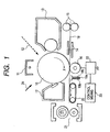
- Fig. 1 is a cross-sectional view of an image forming apparatus which is an embodiment of the present invention.
- the surface of a photosensitive member 10 having a diameter of 30 mm as an image bearing member rotated in the direction of arrow X is uniformly charged by a primary charger 11, and an image light 12 such as an image-modulated laser beam is imparted to the charged surface, whereby the potential of the portion is attenuated and an electrostatic image is formed.
- the toner image is brought to a transfer area formed by a contact transfer charger (transfer roller) 16 and the photosensitive member 10 opposed to each other, a transfer material 18 is directed and conveyed by a transfer entrance guide 14 in timed relationship therewith, and by the action of a transfer electric field formed by the contact transfer charger 16 therewith, the toner image on the photosensitive member 10 is transferred to the transfer material 18.
- a contact transfer charger transfer roller
- transfer material 18 is directed and conveyed by a transfer entrance guide 14 in timed relationship therewith, and by the action of a transfer electric field formed by the contact transfer charger 16 therewith, the toner image on the photosensitive member 10 is transferred to the transfer material 18.
- the transfer material 18 is separated from the photosensitive member 10. Thereafter, the transfer material 18 is conveyed to a fixing device (a pair of fixing rollers) 21 while rubbing against the conveying surface of a conveying member 20, and the toner image is fixed on the transfer material 18. Also, any residual toner on the surface of the photosensitive member 10 is removed by a cleaner 17, whereafter the photosensitive member 10 repeats the steps of being subjected to pre-exposure 24 to thereby reduce the surface potential thereof to nearly OV, and being again charged by the primary charger 11.
- a fixing device a pair of fixing rollers
- the charge eliminating needle 19a is constructed with a protective member (or a guide member serving also to prevent contact) 19b for preventing the transfer material 18 from contacting therewith, and that portion of the conveying member 20 which is nearest to the charge eliminating member 19a and supports the transfer material is constructed at a position higher than the upper end of the protective member 19b and therefore, the trailing end portion of the transfer material which has passed through the transfer area (hereinafter the leading end and the trailing end refer to the ends with respect to the direction of conveyance) is designed to depend from the conveying member 20, and the trailing end portion of the transfer material is more liable to approach the charge removing needle 19a.
- the distance from the transfer area to the conveying member 20 is about 3 cm and the tip end of the charge eliminating needle 19a is located substantially at the middle between the two and 1 to 5 mm below the conveyance path of the transfer material 18.
- the reference numeral 22 designates a transfer voltage source
- the reference numeral 23 denotes transfer voltage control means (CPU)
- a transfer current flowing through the contact transfer charger 16 is constant-current-controlled.
- the transfer voltage control means 23 is adapted to change over the output value of the constant current control at predetermined timing during the execution of transfer.
- the charging polarity of the photosensitive member 10 and the charging polarity of the toner are minus and the polarity of the transfer voltage is plus, and the reversal developing method is used.
- the transfer material supply speed of the image forming apparatus according to the present embodiment is 210 mm/s.
- a voltage of -2.3 kV is applied from a voltage source, not shown, to the charge eliminating needle 19a.
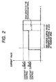
- Fig. 2 shows the control output value of the transfer current in the present embodiment.
- the detection of the transfer material 18 is effected by a sensor, not shown, and at a location of about 30 mm short of the trailing end of the transfer material supplied to the image forming apparatus, the control output value of the transfer charging means 16 is switched (changed over) from 20 ⁇ A to 23 ⁇ A to thereby strengthen the transfer intensity.
- the amount of charge per unit imparted to the trailing end side beyond the output value changeover position becomes greater than that imparted to the leading end side and further, the electrostatic attraction between the transfer material 18 and the photosensitive member 10 becomes stronger and therefore, the trailing end side also passes along a route near 18b in Fig.7, and the amount of the back charges near the trailing end portion of the transfer material flowing to the charge eliminating needle 19a can also be controlled.
- control output value changeover position in the present embodiment is a position of about 30 mm from the trailing end toward the leading end, of course this is not restrictive.
- control output value changeover position is set within the range of 0.5 cm to 5 cm, the deficiency of the back charges near the trailing end portion of the transfer material can be prevented.
- the predetermined changeover position at a position near the leading end portion, and as shown, for example, in Fig. 3, it is also possible to change over the output value at a position of about 40 mm from the leading end toward the trailing end.
- the transfer means has been described as a transfer roller, a transfer charger not in contact with the photosensitive member, such as a corona charger, can also be utilized.
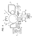
- Fig. 4 is a typical view of an image forming apparatus which is another embodiment of the present invention, and in Fig. 4, the same reference numerals as those in Fig. 1 designate members similar to those in the aforedescribed apparatus, and need not be described.
- the reference character 22a designates a constant current power source
- the reference character 22b denotes a constant voltage source.
- the transfer charging means 16 is constant-current-controlled at 20 ⁇ A, and at a changeover position for increasing the charges imparted to the transfer material, the constant current control is changed over to constant voltage control and the transfer charging means is constant-voltage-controlled by a voltage of a voltage value 5.2 kV determined by the aforementioned ATVC control so that the transfer current may substantially become the order of 30 ⁇ A.
- the transfer charging means 16 is a transfer roller of low to medium resistance which is a volume resistance value of 10 5 to 10 9 ⁇ cm
- the impedance between the transfer roller and the photosensitive member 10 differs greatly depending on the presence or absence of the transfer material in the transfer area, and if in such a case, in an attempt to impart sufficient back charges to the back of the transfer material, the control output value of the transfer voltage is set to a rather great level to thereby effect constant voltage control, when a transfer voltage is applied from before the transfer material arrives at the transfer area, an excessive current flows before the leading end of the transfer material arrives at the transfer area, and the charging memory as previously described is liable to occur.
- the volume resistance value of the transfer material in a low humidity environment becomes about 10 5 to 10 6 times as great as that in a high humidity environment, but during the supply of the transfer material, a leak current directly flowing from the transfer charging means 16 to the charge eliminating needle through the transfer material increases with a change in the distance between the transfer material 18 and the charge eliminating needle and therefore, if constant current control is effected at this time, there arises the problem that particularly in the case of high humidity where the transfer material becomes low in resistance, the current for imparting transfer charges decreases greatly and accordingly, sufficient charges cannot be imparted.
- the transfer charging means is constant-voltage-controlled when the trailing end portion has passed through the transfer area with respect to the direction of conveyance of the transfer material, the charging memory may occur as previously described, but even if the charging memory occurs, the location at which the charging memory has occurred is exposed twice by the pre-exposure means 24 until the next transfer if the photosensitive member 10 makes one full rotation before the next transfer material is conveyed and therefore, the charging memory disappears and no problem in image formation will arise.
- Fig. 5 shows the control output value of the transfer current in the present embodiment.
- the changeover point from constant current control to constant voltage control was effected at a position of 10 mm from the trailing end portion toward the leading end with respect to the direction of conveyance of the transfer material 18.
- the current flowing into the charge eliminating needle 19a by constant voltage control is of the order of 15 ⁇ A, and the amount of charges imparted to the transfer material is of the order of 15 ⁇ A.
- the instability by constant current control is null and the deficiency of charges held near the trailing end portion of the transfer material can be effectively prevented.
- the control of the present embodiment is effected when the longitudinal length of the transfer area in which the transfer charging means 16 and the photosensitive member 10 contact with each other is defined as La and the length of that portion of said La which contacts with the transfer material is defined Lb and the relation that Lb/La > 0.6 is satisfied.
- Still another embodiment of the present invention is directed to effecting optimum control in conformity with the atmospheric environment of the image forming apparatus.
- optimum control is effected in conformity with changes in humidity environment.
- the main construction of the apparatus is similar to that of Embodiment 2 with the exception that a humidity sensor, not shown, as humidity detecting means is added to the image forming apparatus of Fig. 4.
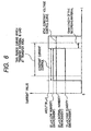
- Fig. 6 shows the control output value of a transfer current in the present embodiment.
- relative humidity of less than 35% is defined as low humidity environment
- relative humidity of 35% to less than 70% (35% or more and less than 70%) is defined as normal humidity environment
- relative humidity of 70% or higher is defined as high humidity environment
- the constant current values for these were 22 ⁇ A, 20 ⁇ A and 15 ⁇ A, respectively.
- the changeover from constant current control to constant voltage control was effected at a position of 10 mm from the trailing end portion toward the leading end with respect to the direction of conveyance of the transfer material 18.
- the resistance value of the transfer material changes greatly depending on humidity environment. As is different depending on the quality of the transfer material, the resistance of a usually used transfer material under low humidity environment is 10 5 to 10 6 times as high as that under high humidity environment. So, if charges are imparted, for example, to all transfer materials of low resistance to high resistance under constant voltage control at the same voltage value, a greater current will flow through a transfer material of low resistance as a matter of course, and many charges will be imparted to the transfer material.
- the target constant current value during constant current control is set to a lower level for the transfer material of low resistance, whereby control conforming to the resistance of the transfer material changed by humidity environment is made possible.
- the target constant current value of constant current control being changed in conformity with humidity environment, good transfer can be done irrespective of humidity environment, but the target constant voltage value during constant voltage control may be changed in conformity with humidity environment.
- the relative humidity is detected and the substance of the control is changed over
- an absolute amount of moisture may be detected, or information such as the thickness, rigidity, size, quality, surface treatment or kind of post-processing of the transfer material may be obtained from detecting means or information inputting means or the like and in conformity with this information, the target value of the control output of constant current control or constant voltage control may be changed or the changeover position of the output value may be changed, whereby transfer materials of more kinds can be coped with.
- the image forming apparatus used in the present invention in order to be comprehensibly illustrated, is of a construction in which the line linking the transfer area and the conveying surface of the conveying member 20 together is substantially horizontal, of course such a construction is not restricted, but the present invention can also be applied to an image forming apparatus of a construction in which the vicinity of the trailing end of a transfer material readily approach the charge eliminating needle 19a.
- the present invention is applicable if the acute angle D1 formed by a straight line linking that portion of the conveying member 20 which is nearest to the charge eliminating member 19a and supports the transfer material and the transfer area together and a horizontal line passing through the transfer area is between +40° and -20° (+ means a case where that portion of the conveying member 20 which is nearest to the charge eliminating member 19a and supports the transfer material is at a position higher than the horizontal line passing through the transfer area, and - means a case where said portion of the conveying member 20 is at a position lower than said horizontal line) and the conveying surface of the conveying member 20 at this time is upwardly or downwardly inclined in the direction of conveyance of the transfer material and the acute angle D2 formed by this surface with respect to the horizontal plane is 5° or less.
- the position of that portion of the conveying member 20 supporting the transfer material which is nearest to the charge eliminating needle 19a is separate by about 3 cm from the transfer area and therefore, this means that the position of that portion of the conveying member 20 supporting the transfer material which is nearest to the charge eliminating needle 19a is between a position higher by about 2 cm than the height of the transfer area and a position lower by about 1 cm than the height of the transfer area.
- D1 is between -20° and +20°
- D2 is 20° or less
- the present invention can be applied, and particularly, when D1 is between -15° and +15° and D2 is 15° or less, the present invention is effective.
- the amount of charges per unit area imparted from a predetermined location on the image formable area of the transfer material to the trailing end side with respect to the direction of conveyance of the transfer material by the transfer means is greater than the amount of charges per unit area imparted from said predetermined location to the leading end side by the transfer means and therefore, the charges imparted to the back of the transfer material by the transfer means can be prevented from excessively flowing to the charge eliminating member to thereby make the back charges deficient and cause the toner to scatter.
Claims (3)
- Bilderzeugungsgerät mit:dadurch gekennzeichnet, dass die Übertragungseinrichtung umfasst:einem bildtragenden Bauteil, das ein Tonerbild trägt,einer Übertragungseinrichtung zur elektrostatischen Übertragung des Tonerbildes auf dem bildtragenden Bauteil auf ein Übertragungsmaterial, undeiner Trenn- und Ladungsableitungseinrichtung zur Ladungsableitung des Übertragungsmaterials, zur Trennung das Übertragungsmaterial von dem bildtragenden Bauteil,wobei die Schalteinrichtung von der Konstantstromsteuerungseinrichtung, die einen Vorgang begonnen hat, bevor eine vordere Kante des Übertragungsmaterials den Spalt erreicht, zu der Konstantspannungsteuerungseinrichtung umschaltet, wenn ein Nahbereich einer hinteren Kante des Übertragungsmaterials den Spalt erreicht,ein Übertragungsbauteil, das mit dem bildtragenden Bauteil einen Spalt bildet;eine Konstantstromsteuerungseinrichtung zur Regelung des Stroms, der dem Übertragungsbauteils zuzuführen ist, auf einen vorgeschriebenen Wert;eine Konstantspannungssteuerungseinrichtung zur Regelung der Spannung, die an das Übertragungsbauteil anzulegen ist, auf einen vorgeschriebenen Wert; undeine Schalteinrichtung zum Umschalten der Konstantstromsteuerungseinrichtung und der Konstantspannungsteuerungseinrichtung,
und wobei ein Stromwert, der dem Übertragungsbauteil von der Konstantspannungsteuerungseinrichtung zuzuführen ist, größer ist als ein Stromwert, der dem Übertragungsbauteil von der Konstantstromsteuerungseinrichtung zuzuführen ist. - Bilderzeugungsgerät gemäß Patentanspruch 1, ferner mit einer Feuchtigkeitserfassungseinrichtung zur Erfassung von Feuchtigkeit,
wobei die Konstantstromsteuerungseinrichtung einen Konstantstromwert entsprechend einem Erfassungsergebnis der Feuchtigkeitserfassungseinrichtung ändert. - Bilderzeugungsgerät gemäß Patentanspruch 1, ferner mit einer Feuchtigkeitserfassungseinrichtung zur Erfassung von Feuchtigkeit,
wobei die Konstantspannungsteuerungseinrichtung einen Konstantspannungswert entsprechend einem Erfassungsergebnis der Feuchtigkeitserfassungseinrichtung ändert.
Applications Claiming Priority (2)
| Application Number | Priority Date | Filing Date | Title |
|---|---|---|---|
| JP34422198 | 1998-12-03 | ||
| JP34422198A JP3368220B2 (ja) | 1998-12-03 | 1998-12-03 | 画像形成装置 |
Publications (3)
| Publication Number | Publication Date |
|---|---|
| EP1006416A2 EP1006416A2 (de) | 2000-06-07 |
| EP1006416A3 EP1006416A3 (de) | 2001-04-25 |
| EP1006416B1 true EP1006416B1 (de) | 2004-12-01 |
Family
ID=18367577
Family Applications (1)
| Application Number | Title | Priority Date | Filing Date |
|---|---|---|---|
| EP99124127A Expired - Lifetime EP1006416B1 (de) | 1998-12-03 | 1999-12-02 | Bilderzeugungsgerät |
Country Status (4)
| Country | Link |
|---|---|
| US (1) | US6334032B1 (de) |
| EP (1) | EP1006416B1 (de) |
| JP (1) | JP3368220B2 (de) |
| DE (1) | DE69922323T2 (de) |
Families Citing this family (8)
| Publication number | Priority date | Publication date | Assignee | Title |
|---|---|---|---|---|
| JP3862543B2 (ja) * | 2000-10-30 | 2006-12-27 | キヤノン株式会社 | 画像形成装置 |
| US6859630B2 (en) * | 2001-12-28 | 2005-02-22 | Ricoh Company, Ltd. | Image transferring and recording medium conveying device and image forming apparatus including the same |
| JP4250373B2 (ja) | 2002-04-17 | 2009-04-08 | キヤノン株式会社 | 画像形成装置 |
| JP5392004B2 (ja) * | 2009-10-28 | 2014-01-22 | コニカミノルタ株式会社 | 除電装置、及びそれを備えた画像形成装置 |
| US8687989B2 (en) * | 2011-11-29 | 2014-04-01 | Eastman Kodak Company | Transfer unit with compensation for variation |
| JP6395377B2 (ja) * | 2013-12-26 | 2018-09-26 | キヤノンファインテックニスカ株式会社 | 画像形成装置 |
| US10754294B2 (en) | 2018-07-31 | 2020-08-25 | Canon Kabushiki Kaisha | Image forming apparatus to reduce deterioration of transferability |
| JP7195804B2 (ja) * | 2018-07-31 | 2022-12-26 | キヤノン株式会社 | 画像形成装置 |
Family Cites Families (11)
| Publication number | Priority date | Publication date | Assignee | Title |
|---|---|---|---|---|
| JPS58122561A (ja) | 1982-01-18 | 1983-07-21 | Ricoh Co Ltd | 複写機の転写方法 |
| JPS61188570A (ja) | 1985-02-16 | 1986-08-22 | Canon Inc | 転写分離装置 |
| JP2704277B2 (ja) | 1988-11-02 | 1998-01-26 | キヤノン株式会社 | 画像形成装置 |
| US5179397A (en) | 1989-04-03 | 1993-01-12 | Canon Kabushiki Kaisha | Image forming apparatus with constant voltage and constant current control |
| US5182604A (en) | 1990-03-17 | 1993-01-26 | Canon Kabushiki Kaisha | Transfer roller with voltage polarity control |
| US5633703A (en) * | 1993-09-16 | 1997-05-27 | Konica Corporation | Image forming apparatus having transfer roller and separation brush |
| US5713063A (en) * | 1994-08-03 | 1998-01-27 | Kabushiki Kaisha Toshiba | Electrostatic image transfer device having a two level transfer voltage for improving image quality at leading and trailing edge regions |
| US5689771A (en) * | 1995-03-02 | 1997-11-18 | Konica Corporation | Color image forming apparatus having bias controller for cleaning transfer roller |
| JP3510008B2 (ja) * | 1995-07-07 | 2004-03-22 | 株式会社沖データ | 印刷装置 |
| US5697015A (en) | 1996-05-29 | 1997-12-09 | Lexmark International, Inc. | Electrophotographic apparatus and method for inhibiting charge over-transfer |
| JP3605961B2 (ja) | 1996-09-20 | 2004-12-22 | 富士ゼロックス株式会社 | 画像形成装置 |
-
1998
- 1998-12-03 JP JP34422198A patent/JP3368220B2/ja not_active Expired - Fee Related
-
1999
- 1999-11-26 US US09/449,971 patent/US6334032B1/en not_active Expired - Lifetime
- 1999-12-02 DE DE69922323T patent/DE69922323T2/de not_active Expired - Lifetime
- 1999-12-02 EP EP99124127A patent/EP1006416B1/de not_active Expired - Lifetime
Also Published As
| Publication number | Publication date |
|---|---|
| EP1006416A3 (de) | 2001-04-25 |
| EP1006416A2 (de) | 2000-06-07 |
| US6334032B1 (en) | 2001-12-25 |
| DE69922323D1 (de) | 2005-01-05 |
| JP3368220B2 (ja) | 2003-01-20 |
| DE69922323T2 (de) | 2005-11-03 |
| JP2000172089A (ja) | 2000-06-23 |
Similar Documents
| Publication | Publication Date | Title |
|---|---|---|
| JP5574213B2 (ja) | 画像形成装置 | |
| US5461461A (en) | Image transferring device and medium separating device for an image forming apparatus | |
| US5198864A (en) | Transfer system with field tailoring | |
| EP1006416B1 (de) | Bilderzeugungsgerät | |
| JP3630903B2 (ja) | 画像形成装置 | |
| JP4227446B2 (ja) | 画像形成装置 | |
| JP3605961B2 (ja) | 画像形成装置 | |
| US5784668A (en) | Image forming apparatus | |
| US5771432A (en) | Image formation system with toner scattering prevention | |
| JPH11338276A (ja) | 画像形成装置 | |
| JP3659302B2 (ja) | 画像形成装置 | |
| JP3271811B2 (ja) | 画像形成装置 | |
| JP3581525B2 (ja) | 画像形成装置 | |
| JPH07334018A (ja) | 画像形成装置の制御方法 | |
| JP3368222B2 (ja) | 画像形成装置 | |
| JPH05333722A (ja) | 画像形成装置 | |
| JPH11231596A (ja) | 画像形成装置 | |
| JP3577910B2 (ja) | 画像形成装置 | |
| JPH0594095A (ja) | 電子写真記録装置 | |
| JP2002049252A (ja) | 画像形成装置 | |
| JP2005179034A (ja) | 画像形成装置及びこれに用いられる記録材案内処理装置 | |
| JP2005084213A (ja) | 画像形成装置 | |
| JP2004191662A (ja) | 画像形成装置 | |
| JP2941934B2 (ja) | 画像形成装置 | |
| JPH0540418A (ja) | 画像形成装置 |
Legal Events
| Date | Code | Title | Description |
|---|---|---|---|
| PUAI | Public reference made under article 153(3) epc to a published international application that has entered the european phase |
Free format text: ORIGINAL CODE: 0009012 |
|
| AK | Designated contracting states |
Kind code of ref document: A2 Designated state(s): DE FR GB IT |
|
| AX | Request for extension of the european patent |
Free format text: AL;LT;LV;MK;RO;SI |
|
| PUAL | Search report despatched |
Free format text: ORIGINAL CODE: 0009013 |
|
| AK | Designated contracting states |
Kind code of ref document: A3 Designated state(s): AT BE CH CY DE DK ES FI FR GB GR IE IT LI LU MC NL PT SE |
|
| AX | Request for extension of the european patent |
Free format text: AL;LT;LV;MK;RO;SI |
|
| 17P | Request for examination filed |
Effective date: 20010906 |
|
| AKX | Designation fees paid |
Free format text: DE FR GB IT |
|
| 17Q | First examination report despatched |
Effective date: 20030729 |
|
| GRAP | Despatch of communication of intention to grant a patent |
Free format text: ORIGINAL CODE: EPIDOSNIGR1 |
|
| GRAS | Grant fee paid |
Free format text: ORIGINAL CODE: EPIDOSNIGR3 |
|
| GRAA | (expected) grant |
Free format text: ORIGINAL CODE: 0009210 |
|
| AK | Designated contracting states |
Kind code of ref document: B1 Designated state(s): DE FR GB IT |
|
| REG | Reference to a national code |
Ref country code: GB Ref legal event code: FG4D |
|
| REF | Corresponds to: |
Ref document number: 69922323 Country of ref document: DE Date of ref document: 20050105 Kind code of ref document: P |
|
| ET | Fr: translation filed | ||
| PLBE | No opposition filed within time limit |
Free format text: ORIGINAL CODE: 0009261 |
|
| STAA | Information on the status of an ep patent application or granted ep patent |
Free format text: STATUS: NO OPPOSITION FILED WITHIN TIME LIMIT |
|
| 26N | No opposition filed |
Effective date: 20050902 |
|
| PGFP | Annual fee paid to national office [announced via postgrant information from national office to epo] |
Ref country code: IT Payment date: 20081211 Year of fee payment: 10 |
|
| PGFP | Annual fee paid to national office [announced via postgrant information from national office to epo] |
Ref country code: FR Payment date: 20081222 Year of fee payment: 10 |
|
| REG | Reference to a national code |
Ref country code: FR Ref legal event code: ST Effective date: 20100831 |
|
| PG25 | Lapsed in a contracting state [announced via postgrant information from national office to epo] |
Ref country code: FR Free format text: LAPSE BECAUSE OF NON-PAYMENT OF DUE FEES Effective date: 20091231 |
|
| PG25 | Lapsed in a contracting state [announced via postgrant information from national office to epo] |
Ref country code: IT Free format text: LAPSE BECAUSE OF NON-PAYMENT OF DUE FEES Effective date: 20091202 |
|
| PGFP | Annual fee paid to national office [announced via postgrant information from national office to epo] |
Ref country code: GB Payment date: 20151218 Year of fee payment: 17 |
|
| PGFP | Annual fee paid to national office [announced via postgrant information from national office to epo] |
Ref country code: DE Payment date: 20151231 Year of fee payment: 17 |
|
| REG | Reference to a national code |
Ref country code: DE Ref legal event code: R119 Ref document number: 69922323 Country of ref document: DE |
|
| GBPC | Gb: european patent ceased through non-payment of renewal fee |
Effective date: 20161202 |
|
| PG25 | Lapsed in a contracting state [announced via postgrant information from national office to epo] |
Ref country code: DE Free format text: LAPSE BECAUSE OF NON-PAYMENT OF DUE FEES Effective date: 20170701 Ref country code: GB Free format text: LAPSE BECAUSE OF NON-PAYMENT OF DUE FEES Effective date: 20161202 |