EP1004834A2 - Systèmes de conditionnement d'air - Google Patents
Systèmes de conditionnement d'air Download PDFInfo
- Publication number
- EP1004834A2 EP1004834A2 EP99123172A EP99123172A EP1004834A2 EP 1004834 A2 EP1004834 A2 EP 1004834A2 EP 99123172 A EP99123172 A EP 99123172A EP 99123172 A EP99123172 A EP 99123172A EP 1004834 A2 EP1004834 A2 EP 1004834A2
- Authority
- EP
- European Patent Office
- Prior art keywords
- passage
- pressure
- driving chamber
- compressor
- discharge
- Prior art date
- Legal status (The legal status is an assumption and is not a legal conclusion. Google has not performed a legal analysis and makes no representation as to the accuracy of the status listed.)
- Withdrawn
Links
Images


Classifications
-
- F—MECHANICAL ENGINEERING; LIGHTING; HEATING; WEAPONS; BLASTING
- F25—REFRIGERATION OR COOLING; COMBINED HEATING AND REFRIGERATION SYSTEMS; HEAT PUMP SYSTEMS; MANUFACTURE OR STORAGE OF ICE; LIQUEFACTION SOLIDIFICATION OF GASES
- F25B—REFRIGERATION MACHINES, PLANTS OR SYSTEMS; COMBINED HEATING AND REFRIGERATION SYSTEMS; HEAT PUMP SYSTEMS
- F25B6/00—Compression machines, plants or systems, with several condenser circuits
- F25B6/04—Compression machines, plants or systems, with several condenser circuits arranged in series
-
- B—PERFORMING OPERATIONS; TRANSPORTING
- B60—VEHICLES IN GENERAL
- B60H—ARRANGEMENTS OF HEATING, COOLING, VENTILATING OR OTHER AIR-TREATING DEVICES SPECIALLY ADAPTED FOR PASSENGER OR GOODS SPACES OF VEHICLES
- B60H1/00—Heating, cooling or ventilating [HVAC] devices
- B60H1/32—Cooling devices
- B60H1/3204—Cooling devices using compression
- B60H1/3223—Cooling devices using compression characterised by the arrangement or type of the compressor
-
- F—MECHANICAL ENGINEERING; LIGHTING; HEATING; WEAPONS; BLASTING
- F04—POSITIVE - DISPLACEMENT MACHINES FOR LIQUIDS; PUMPS FOR LIQUIDS OR ELASTIC FLUIDS
- F04B—POSITIVE-DISPLACEMENT MACHINES FOR LIQUIDS; PUMPS
- F04B27/00—Multi-cylinder pumps specially adapted for elastic fluids and characterised by number or arrangement of cylinders
- F04B27/08—Multi-cylinder pumps specially adapted for elastic fluids and characterised by number or arrangement of cylinders having cylinders coaxial with, or parallel or inclined to, main shaft axis
- F04B27/14—Control
- F04B27/16—Control of pumps with stationary cylinders
- F04B27/18—Control of pumps with stationary cylinders by varying the relative positions of a swash plate and a cylinder block
- F04B27/1804—Controlled by crankcase pressure
-
- F—MECHANICAL ENGINEERING; LIGHTING; HEATING; WEAPONS; BLASTING
- F25—REFRIGERATION OR COOLING; COMBINED HEATING AND REFRIGERATION SYSTEMS; HEAT PUMP SYSTEMS; MANUFACTURE OR STORAGE OF ICE; LIQUEFACTION SOLIDIFICATION OF GASES
- F25B—REFRIGERATION MACHINES, PLANTS OR SYSTEMS; COMBINED HEATING AND REFRIGERATION SYSTEMS; HEAT PUMP SYSTEMS
- F25B41/00—Fluid-circulation arrangements
- F25B41/20—Disposition of valves, e.g. of on-off valves or flow control valves
- F25B41/24—Arrangement of shut-off valves for disconnecting a part of the refrigerant cycle, e.g. an outdoor part
-
- F—MECHANICAL ENGINEERING; LIGHTING; HEATING; WEAPONS; BLASTING
- F04—POSITIVE - DISPLACEMENT MACHINES FOR LIQUIDS; PUMPS FOR LIQUIDS OR ELASTIC FLUIDS
- F04B—POSITIVE-DISPLACEMENT MACHINES FOR LIQUIDS; PUMPS
- F04B27/00—Multi-cylinder pumps specially adapted for elastic fluids and characterised by number or arrangement of cylinders
- F04B27/08—Multi-cylinder pumps specially adapted for elastic fluids and characterised by number or arrangement of cylinders having cylinders coaxial with, or parallel or inclined to, main shaft axis
- F04B27/14—Control
- F04B27/16—Control of pumps with stationary cylinders
- F04B27/18—Control of pumps with stationary cylinders by varying the relative positions of a swash plate and a cylinder block
- F04B27/1804—Controlled by crankcase pressure
- F04B2027/184—Valve controlling parameter
- F04B2027/185—Discharge pressure
-
- F—MECHANICAL ENGINEERING; LIGHTING; HEATING; WEAPONS; BLASTING
- F25—REFRIGERATION OR COOLING; COMBINED HEATING AND REFRIGERATION SYSTEMS; HEAT PUMP SYSTEMS; MANUFACTURE OR STORAGE OF ICE; LIQUEFACTION SOLIDIFICATION OF GASES
- F25B—REFRIGERATION MACHINES, PLANTS OR SYSTEMS; COMBINED HEATING AND REFRIGERATION SYSTEMS; HEAT PUMP SYSTEMS
- F25B2400/00—General features or devices for refrigeration machines, plants or systems, combined heating and refrigeration systems or heat-pump systems, i.e. not limited to a particular subgroup of F25B
- F25B2400/04—Refrigeration circuit bypassing means
- F25B2400/0403—Refrigeration circuit bypassing means for the condenser
-
- F—MECHANICAL ENGINEERING; LIGHTING; HEATING; WEAPONS; BLASTING
- F25—REFRIGERATION OR COOLING; COMBINED HEATING AND REFRIGERATION SYSTEMS; HEAT PUMP SYSTEMS; MANUFACTURE OR STORAGE OF ICE; LIQUEFACTION SOLIDIFICATION OF GASES
- F25B—REFRIGERATION MACHINES, PLANTS OR SYSTEMS; COMBINED HEATING AND REFRIGERATION SYSTEMS; HEAT PUMP SYSTEMS
- F25B2400/00—General features or devices for refrigeration machines, plants or systems, combined heating and refrigeration systems or heat-pump systems, i.e. not limited to a particular subgroup of F25B
- F25B2400/04—Refrigeration circuit bypassing means
- F25B2400/0411—Refrigeration circuit bypassing means for the expansion valve or capillary tube
-
- F—MECHANICAL ENGINEERING; LIGHTING; HEATING; WEAPONS; BLASTING
- F25—REFRIGERATION OR COOLING; COMBINED HEATING AND REFRIGERATION SYSTEMS; HEAT PUMP SYSTEMS; MANUFACTURE OR STORAGE OF ICE; LIQUEFACTION SOLIDIFICATION OF GASES
- F25B—REFRIGERATION MACHINES, PLANTS OR SYSTEMS; COMBINED HEATING AND REFRIGERATION SYSTEMS; HEAT PUMP SYSTEMS
- F25B49/00—Arrangement or mounting of control or safety devices
- F25B49/02—Arrangement or mounting of control or safety devices for compression type machines, plants or systems
- F25B49/022—Compressor control arrangements
Definitions
- the present invention relates to air conditioning systems that utilize refrigerants and a compressor, and particularly to air conditioning systems capable of effectively alleviating excessive increases in refrigerant discharge pressure within a heating circuit.
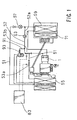
- a known air conditioning system is disclosed in Japanese Patent Application No. 7-19630 and includes a compressor 1, a cooling circuit 51, a heating circuit 52 and a controller 83, as shown in FIG. 1.
- the cooling circuit 51 includes a condenser 55, a first expansion valve 57, and a heat exchanger 59 provided on a passage connecting a discharge port D to a suction port S of the compressor 1. High-pressure refrigerant discharged from the discharge port of the compressor 1 is drawn through the above respective devices and back to the compressor 1.
- the heating circuit 52 includes a bypass passage 52a that extends from the discharge port D of the compressor 1 to the heat exchanger 59.
- a second expansion valve 63 is provided within the bypass passage 52a between the discharge port D and the heat exchanger 59.
- the high pressure refrigerant discharged from the compressor 1 is not directed to the condenser 55, but rather is drawn by the compressor 1 through the second expansion valve 63 and the heat exchanger 59 and this cycle is repeated.
- Such a heating circuit 52 is generally known as a hot-gas bypass heater.
- the operation of the cooling circuit 51 and the heating circuit 52 is changeably selected by opening and closing selector valves 53a and 53b, which opening and closing operations are performed by the controller 83.
- the air conditioning system is used in a state in which the refrigerant discharge pressure is higher when the heating circuit 52 is used than when the cooling circuit 51 is used, abnormally high pressure is likely to be applied during operation of the heating circuit 52.
- the abnormally high-pressure state is likely to occur when a rotation speed of the compressor 1 is increased temporarily during operation of the heating circuit 52. Therefore, the air conditioning system is further provided with a refrigerant releasing passage 91 having a pressure relief valve 93.
- the refrigerant releasing passage 91 is connected to the heating circuit 52 and the cooling circuit 51 and the pressure relief valve 93 can be opened to release the refrigerant from the heating circuit 52 to the cooling circuit 51 when the refrigerant discharge pressure abnormally increases during the operation of the heating circuit 52.
- the refrigerant is released toward the cooling circuit 51 which is not used when the discharge pressure is increased abnormally during operation of the heating circuit 52, thereby preventing the discharge pressure at the heating circuit 52 from increasing abnormally.
- the refrigerant is released from the operating heating circuit 52 to the cooling circuit 51 which is not used, the abnormally high-pressure state of the discharge pressure during operation of the heating circuit 52 can be alleviated.
- the refrigerant in the heating circuit 52 is released into the cooling circuit 51 whenever the discharge pressure increases, the amount of the refrigerant in the heating circuit 52 is reduced and heating performance may be reduced.
- the high- pressure refrigerant is wastefully released from the heating circuit by working the compressor 1, energy efficiency is reduced.
- an object of the present invention to provide an air conditioning system that can effectively alleviate abnormally high pressure state.
- the air conditioning system may include a compressor, a heating circuit, and a capacity controller.
- the compressor has a suction port, a discharge port, a driving unit provided within a compressor driving chamber, a first passage and a second passage.
- the driving unit may decrease compressor output discharge capacity when the pressure within the driving chamber increases.
- the first passage may connect the discharge port to the driving chamber and the second passage may connect the driving chamber to the suction port.
- the capacity controller may open the first passage when the refrigerant discharge pressure results predetermined pressure. By opening the first passage, the high-pressure refrigerant may be released from the discharge port to the driving chamber through the first passage.
- the pressure within the driving chamber may increase.
- the compressor output discharge capacity can be reduced. As the result, the discharge pressure of the compressor will be reduced by the reduction in the compressor output discharge capacity.
- the air conditioning system can solve a problem of insufficient heating performance due to release of the refrigerant within the heating circuit into the cooling circuit for alleviating the abnormally high-pressure state of the discharge pressure during operation of the heating circuit.
- the air conditioner can solve a problem of low energy efficiency due to wasteful release of the high-pressure refrigerant from the heating circuit to the outside.
- the air conditioning system may preferably include a capacity controller that can close the second passage when the refrigerant discharge pressure results predetermined pressure.
- the high-pressure refrigerant may be released at all times from the discharge port to the driving chamber through the first passage.
- the refrigerant within the driving chamber may be released into the suction port through the second passage in a normal operation of the air conditioning system.
- the capacity controller close the second passage when the discharge pressure results predetermined pressure.
- the pressure within the driving chamber may increase.
- the compressor discharge capacity can be reduced.
- the discharge pressure of the compressor can be reduced by the reduction in the compressor output discharge capacity.
- an air conditioning system may include a compressor, a heating circuit, and a capacity controller.
- the compressor may include a suction port, a discharge port, a driving unit, a first passage and a second passage.
- the suction port may draw the refrigerant into the compressor.
- the discharge port may discharge compressed high-pressure refrigerant.
- the driving unit may be provided within a compressor driving chamber. The driving unit may decrease compressor output discharge capacity when the pressure within the driving chamber increases.
- the first passage may connect the discharge port to the driving chamber.
- the second passage may connect the driving chamber to the suction port.
- the heating circuit may have a passage that extends from the discharge port to the suction port through the heat exchanger.
- Such type of the heating circuit is generally known as a hot gas bypass heater.
- a decompressor such as an expansion valve may be provided within the passage from the discharge port to the heat exchanger.
- the capacity controller may close the first passage when the refrigerant discharge pressure does not result predetermined pressure i.e., in a normal operation of the air conditioning system. By closing the first passage, the high-pressure refrigerant can not be released from the discharge port to the driving chamber. Thus, the pressure within the driving chamber does not increase and the compressor output discharge capacity can not be decreased.
- the capacity controller may open the first passage when the refrigerant discharge pressure results predetermined pressure. By opening the first passage, the high-pressure refrigerant may be released from the discharge port to the driving chamber through the first passage. Thus, the pressure within the driving chamber may increase. By increasing the pressure within the driving chamber, the compressor discharge capacity can be reduced.
- the air conditioning system can effectively alleviate the abnormal high discharge pressure of the refrigerant especially during the operation of the heating circuit by decreasing the output discharge capacity of the compressor.
- the output discharge capacity may be decreased by opening the first passage.
- a throttle may be provided within the second passage to maintain the high-pressure state within the driving chamber such that the driving unit can decrease the output discharge capacity sufficiently.
- the capacity controller may include a valve that is disposed within the first passage.
- the valve may open the first passage when the refrigerant discharge pressure results the predetermined pressure. As the result, the refrigerant is released from the discharge port into the driving chamber through the first passage thereby increasing the pressure within the driving chamber, decreasing the compressor output discharge capacity, and decreasing the refrigerant discharge pressure.
- the valve is, for example, one of the features corresponding to the capacity controller or means for opening the first passage.
- another type of capacity controller may be utilized in the air conditioning system.
- the high-pressure refrigerant may be released at all times from the discharge port into the driving chamber through the first passage.
- the capacity controller may open the second passage when the refrigerant discharge pressure does not result predetermined high-pressure i.e., in a normal operation of the air conditioning system.
- the high-pressure refrigerant released from the discharge port to the driving chamber can not be retained within the driving chamber and released from the driving chamber into the suction port through the second passage.
- the pressure within the driving chamber does not increase and the compressor output discharge capacity can not be decreased, thereby maintaining the circuit operating performance.
- the capacity controller may close the second passage when the refrigerant discharge pressure results predetermined high pressure.
- the high-pressure refrigerant released from the discharge port into the driving chamber through the first passage may be retained within the driving chamber.
- the pressure within the driving chamber may increase.
- the compressor discharge capacity can be reduced. As the result, the discharge pressure of the compressor is reduced by the reduction in the compressor discharge capacity.
- the capacity controller may include a valve that is disposed within the second passage.
- the valve may close the second passage when the refrigerant discharge pressure results predetermined high pressure.
- the valve is, for example, one of the features corresponding to the capacity controller or means for closing the second passage.
- the first passage for connecting the discharge port to the driving chamber may preferably be defined by a clearance between a compressor cylinder bore and a compressor piston.
- the first passage in the second representative example may preferably include the clearance between the cylinder bore and the piston. Because the cylinder bore and the piston are provided between the discharge port and the driving chamber, the first passage can be easily constructed without forming any specific passage within the compressor. Therefore, the structure of the air conditioning system can be simplified.
- a representative air conditioning system 100 may include a cooling circuit 151, a heating circuit 152 and a variable displacement compressor 101 as a driving source for both the heating and cooling circuits.
- a representative capacity controller is shown in FIG. 3, but is not shown in FIG. 2 for the sake of convenience and will be described below in further detail.
- Such the air conditioning system 100 may be utilized in a vehicle-mounted air conditioning system.
- a driving shaft 125 of the compressor 100 may be coupled to and driven by an automobile engine 170.
- the cooling circuit 151 may be driven by high-pressure refrigerant, which is compressed by the compressor 101, and may include a condenser 155, a first expansion valve 157, a heat exchanger 159 and an accumulator 161. These devices may be disposed within a path 151a that extends from a discharge port D to a suction port S of the compressor 101.
- the heat exchanger 159 is also generally known as an evaporator.
- the heat exchanger 159 may be arranged side by side with a hot-water heater 171, which circulates hot coolant from the engine 170 through a pipe 173.
- the heating circuit 152 is driven by high-temperature and high-pressure refrigerant, which is also compressed by the compressor 101, and may include a second expansion valve 163, the heat exchanger 159 and the accumulator 161. These devices may be disposed on a bypass passage 152a for introducing the refrigerant discharged from the discharge port D to the heat exchanger 159. In other words, the heating circuit 152 partially overlaps with the cooling circuit 151.
- Such a heating circuit 152 is also generally known as a hot-gas bypass heater.
- a first open/close valve 153a and a second open/close valve 153b may be utilized as switch valves for alternatively actuating the cooling circuit 151 and the heating circuit 152.
- the refrigerant is compressed by the compressor 101 to attain a high temperature and high pressure state.
- the compressed refrigerant is sent to the condenser 155, where heat from the high-temperature refrigerant is dissipated to the outside environment and the refrigerant is liquefied.
- the refrigerant is decompressed by the first expansion valve 157 and sent to the heat exchanger 159 where the refrigerant absorbs outside heat and is gasified.
- the gasified refrigerant is returned to the compressor 101 again through the accumulator 161 for re-circulation throughout the system 100.
- the refrigerant is compressed by the compressor 101 to attain a high temperature and high pressure state.
- the compressed refrigerant is then decompressed by the second expansion valve 163 and sent to the heat exchanger 159, where heat from the compressed refrigerant is dissipated to the outside environment.
- the refrigerant is constantly in a gaseous state while circulating through the heating circuit 152.
- the heating circuit 152 may be used as an auxiliary heater. Heat generated by the heat exchanger 159 during operation of the heating circuit 152 may be used as an auxiliary heating source for the hot water heater 171. The heating circuit 152 also may be used to assist the coolant from the engine 170 when the coolant can not provide sufficient heat to start the engine 170 in a low-temperature environment, such as an outside air temperature of ⁇ 20°C or so.
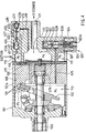
- a representative compressor 101 may include a driving chamber 110 defined within a housing 101a of the compressor 101 and a swash plate 130 that is rotatably supported by the driving shaft 125 in the driving chamber 110.
- the swash plate 130 may be supported by the driving shaft 125 and may rotate together with the drive shaft 125.
- the swash plate 130 is inclined with respect to the driving shaft 125 when the driving shaft 125 rotates and the inclination angle of the swash plate 130 with respect to a plane perpendicular to the axis of rotation of the driving shaft 125 is changeable.
- the peripheral edge portion of the swash plate 130 may be connected to the head portions of the pistons 135 by means of movable shoes 131.
- Six pistons 135 in total may be disposed around the driving shaft 125 (however, only one piston is shown in FIG. 3 for the sake of convenience) and may be laterally slide within six cylinder bores 109. The circumferential positions of the six cylinder bores 109 are fixed by the compressor housing 101a.
- a suction port 118a and a discharge port 123a are defined in a bottom portion of each the cylinder bore 109.
- a suction valve 118 is positioned to correspond to the suction port 118a and a discharge valve 123 is positioned to correspond to the discharge port 123a.
- Each suction port 118a communicates with a suction chamber 115 and each the discharge port 123a communicates with a discharge chamber 120.
- the output discharge capacity of the compressor 101 is determined by the stroke length of the piston 135, which is determined by the degree of change in inclination angle of the swash plate 130 during each cycle. That is, the further the swash plate 130 is withdrawn from the cylinder bore 109 during each cycle, the longer the stroke length of the piston 135 will be. As the stroke length decreases, the output discharge capacity of the compressor 101 also decreases.
- the inclination angle of the swash plate 130 is determined, in part, by the difference in pressure on the opposite sides of the piston 135, i.e., the pressure difference between driving chamber pressure and the cylinder bore pressure. Increasing or decreasing the driving chamber pressure can adjust this pressure difference.
- the pressure within the driving chamber 110 is increased, the swash plate 130 does not move as much in the lateral direction and the stroke length of the piston 135 decreases. Therefore, the output discharge capacity also will decrease.
- the output discharge capacity decreases, the refrigerant discharge pressure decreases and the suction pressure increases.
- the pressure within the driving chamber 110 is decreased, the swash plate 130 will move further in the lateral direction, the stroke length of the piston 135 increases. In this case, the output discharge capacity will increase.
- the refrigerant discharge pressure increases and the suction pressure decreases.
- the high-pressure refrigerant in the discharge chamber 120 is released into the driving chamber 110 to increase the pressure within the driving chamber 110.
- the refrigerant in the discharge chamber 120 is prevented from being released into the driving chamber 110.
- Such control of changing the output discharge capacity by releasing ot not releasing the refrigerant from the discharge chamber to the driving chamber is defined as "releasing-sided control”.
- the discharge chamber 120 and the driving chamber 110 are connected by a heating circuit capacity control passage 201 and also by a cooling circuit capacity control passage 301.
- a heating circuit capacity control valve 181 is provided within the heating circuit capacity control passage 201.
- the driving chamber 110 is connected to the suction chamber 115 by a bleeding passage 105.
- a throttle (not particularly shown in the drawings) is provided onto the bleeding passage 105.
- the discharge chamber 120 is connected to the heating circuit capacity control valve 181 by a first heating circuit capacity control passage 201a. Therefore, pressure in the first heating circuit capacity control passage 201a is equal to the discharge pressure Pd.
- the heating circuit capacity control valve 181 is connected to the driving chamber 110 by a second heating circuit capacity control passage 201b. Therefore, the pressure in the second heating circuit capacity control passage 201b is equal to the pressure Pc within the driving chamber.
- a valve body 203 is biased to close the heating circuit capacity control passage 201 by utilizing a spring 205.
- the first heating circuit capacity control passage 201a and the second heating circuit capacity control passage 201b are not connected in a normal operation of the heating circuit.
- the valve body 203 moves to open the heating circuit capacity control valve 181.
- a condition for opening the heating circuit capacity control valve 181 can be determined by properly adjusting the biasing force of the spring 205. In the first embodiment, the biasing force of the spring 205 is adjusted to open the heating circuit capacity control valve 181 when the discharge pressure Pd results predetermined high-pressure state during operation of the heating circuit.
- the discharge chamber 120 is connected to the driving chamber 110 by the cooling circuit capacity control passage 301.
- a cooling circuit capacity control valve 183 is provided within the cooling circuit capacity control passage 301.
- the discharge chamber 120 is connected to the cooling circuit capacity control valve 183 by a first cooling circuit capacity control passage 301a. Therefore, pressure in the first cooling circuit capacity control passage 301a is equal to the discharge pressure Pd.
- the cooling circuit capacity control valve 183 is connected to the driving chamber 110 by a second cooling circuit capacity control passage 301b. Therefore, pressure in the second cooling circuit capacity control passage 301b is equal to the pressure Pc in the driving chamber 110.
- the cooling circuit capacity control valve 183 includes a valve body 305, an actuating member 307a actuated by a solenoid 307, a connecting member 307b for connecting the actuating member 307a to the valve body 305 and a bellows 305a.
- the bellows 305a can expand and contract to move the valve body 305 in accordance with the suction pressure Ps.
- the suction pressure Ps for expanding or contracting the bellows 305a may be detected through a suction pressure detecting passage 303 that is connected to the suction chamber 115.
- the bellows 305a opens the valve body 305 to communicate the first cooling circuit capacity control passage 301a with the second cooling circuit capacity control passage 301b when the suction pressure Ps meets the condition of opening the valve body 305.
- Such condition may be changed by exciting or not exciting the solenoid 307.
- a controller (not particularly shown in the drawings) generates a control signal for exciting or not exciting the solenoid 307. This is because the force exerted onto the actuating member 307a by the solenoid 309 is utilized as a biasing force against the movement of the bellows 305a.
- the solenoid 307 is excited to close the cooling circuit capacity control valve 183, because the output discharge capacity is to be controlled exclusively by utilizing the heating circuit capacity control valve 181 during operation of the heating circuit.
- the discharge pressure Pd of the refrigerant results predetermined high pressure during operation of the heating circuit 152
- the difference between the discharge pressure Pd and the pressure Pc within the driving chamber 110 increases and the valve body 203 of the heating circuit capacity control valve 181 is moved to communicate the first heating circuit capacity control passage 201a with the second heating circuit capacity control passage 201b.
- the refrigerant is released from the discharge chamber 120 into the driving chamber 110 through the heating circuit capacity control passage 201.
- the pressure Pc within the driving chamber 110 increases.
- the swash plate 130 stands (i.e., the inclination angle of the swash plate 130 decreases)
- the stroke length of the piston 135 decreases
- the output discharge capacity of the compressor 101 decreases
- the discharge pressure Pd decreases.
- the amount of the refrigerant necessary for decreasing the output discharge capacity is relatively small. Therefore, extreme reduction of the energy sufficiency does not occur.
- the heating circuit capacity control valve 181 is closed, because the discharge pressure Pd does not prevail over the biasing force of the spring 205. Therefore, the heating circuit capacity control passage 201 is closed and the refrigerant is not released form the discharge chamber 120 into the driving chamber 110.
- the throttle is provided within the bleeding passage 105, the refrigerant released from the discharge chamber 120 into the driving chamber 110 may be retained in the driving chamber 110 thereby maintaining the high-pressure state within the driving chamber 110 for sufficiently decreasing the compressor output discharge capacity.
- the bellows 305a of the cooling circuit capacity control valve 183 is expanded by the biasing force of a spring 305c and the valve 305 moves to communicate the first cooling circuit capacity control passage 301a with the second cooling circuit capacity control passage 301b.
- the refrigerant is released from the discharge chamber 120 into the driving chamber 110 through the cooling circuit capacity control passage 301.
- the pressure within the driving chamber 110 increases and the compressor output discharge capacity decreases.
- the suction pressure Ps increases and the heat exchanger 159 (shown in FIG.2) is prevented from being frosted.
- the cooling circuit capacity control valve 183 is necessarily to be closed because the discharge pressure is controlled exclusively by the heating circuit capacity control valve 181. Therefore, when the heating circuit is operated, the solenoid 307 is not excited. Thus, the cooling circuit capacity control passage 301 is closed during the operation of the heating circuit.
- the heating circuit capacity control valve 181 is necessarily to be closed because the suction pressure is controlled exclusively by utilizing the cooling circuit capacity control valve 183.
- the heating circuit capacity control valve 181 utilizes the difference between the discharge pressure Pd and the pressure within the driving chamber 110. Therefore, during operation of the cooling circuit, the heating circuit capacity control valve 181 may possibly be opened when the discharge pressure Pd particularly increases with respect to the pressure within the driving chamber 110.
- the pressure necessary for opening the heating circuit capacity control valve 181 is set to be higher than the discharge pressure for operating the cooling circuit. Therefore, the heating circuit capacity control valve 181 is unlikely opened during operation of the cooling circuit.
- the heating circuit capacity control valve 181 can swiftly be closed causing no practical damage onto the air conditioning system.
- the refrigerant is not released from the discharge side to the suction side to decrease the discharge pressure by the direct action of such release. Instead, a small amount of refrigerant is released into the driving chamber to increase the pressure within the driving chamber, decrease the inclination angle of the swash plate, decrease the piston stroke length and decrease the output discharge capacity, thereby decreasing the discharge pressure.
- wasted system energy required to alleviate the abnormally high-pressure state of the discharge pressure is reduced to a minimum.
- the driving chamber 110 is connected to the suction chamber 115 through the bleeding passage 105, the refrigerant released from the discharge chamber 120 builds up temporality in the driving chamber 110 and is not released directly into the suction chamber 120. Therefore, the suction pressure Ps is prevented from increasing by being directly affected by release of the high-pressure refrigerant. As a result, the decreasing effect of the discharge pressure Pd can be maintained for a relatively long time. In this sense, release of the refrigerant into the driving chamber 110 in the embodiment has significance in substantially using the driving chamber 110 as a reserve tank.
- the heating circuit capacity control valve 181 utilizes the difference between the discharge pressure Pd and the pressure within the driving chamber 110
- the heating circuit capacity control valve 181 may be opened by utilizing another difference in pressure.
- suction pressure may preferably be utilized instead of the pressure within the driving chamber.
- a solenoid valve that is opened or closed by the controller like the cooling circuit capacity control valve 183 may preferably be utilized to the heating circuit capacity control valve.
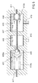
- FIG. 4 A second detailed representative embodiment is shown in FIG. 4 and includes a different type of capacity control structure from the first representative embodiment.
- the discharge chamber 120 is connected to the driving chamber 110 by a refrigerant release passage 515.
- a throttle is provided within the refrigerant release passage 515 although it is not particularly shown in FIG. 4.
- the driving chamber 110 is connected to the suction port 115 through a first heating circuit refrigerant bleeding passage 415 and a second heating circuit refrigerant bleeding passage 417.
- a heating circuit capacity control valve 400 is provided between the both first and second heating circuit bleeding passage 415,417.
- the driving chamber 110 is also connected to the suction port 115 through a first cooling circuit refrigerant bleeding passage 505 and a second cooling circuit refrigerant bleeding passage 507.
- a cooling circuit capacity control valve 500 is provided between the both first and second cooling circuit bleeding passage 505,507.
- a first section chamber 401 communicates with the suction chamber 115 through the second heating circuit capacity control passage 417.
- a second section chamber 402 communicates with the driving chamber 110 through the first heating circuit capacity control passage 415.
- a third section chamber 403 communicates with the discharge chamber 120 through a discharge pressure detecting passage 419.
- a valve body 405 disposed in the first section chamber 401. As shown in FIG. 4, the valve body 405 communicates the first section chamber 401 with the second section chamber 402 during the normal operation of the heating circuit.
- a bellows 409 is provided within the third section chamber 403 and atmospheric pressure is introduced into the bellows 409 through an atmospheric pressure introducing passage 411.
- the third section chamber 403 communicates with the discharge chamber 120 through the discharge pressure detecting passage 419 but does not communicate with the another section chambers 401, 402.
- the bellows 409 is connected to the valve body 405 by means of a connecting member 407.
- the cooling circuit capacity control valve 500 includes a bellows 501, a valve body 503, an actuating member 503a and a solenoid 504.
- the bellows 501, the valve body 503 and the actuating member 503b are integrally connected by utilizing a connecting bar 503b.
- the bellows 501 can expand or contract to open or close the valve body 503 in response to the suction pressure Ps.
- the suction pressure Ps is detected by utilizing the second cooling circuit refrigerant bleeding passage 507.
- a spring 502 is provided within the bellows 501 for biasing the valve body 503 to be closed.
- the solenoid 504 is excited or not excited by the solenoid 504 for adjusting the biasing force.
- the solenoid 504 is excited, the actuating member 503b moves toward the valve body 503 and the connecting bar 503b pushes the valve body 503 to facilitate opening of the passage.
- the valve body 503 closes the passage, the pressure within the driving chamber 110 increases because the high-pressure refrigerant released from the discharge chamber 120 into the driving chamber 110 is retained within the driving chamber 120.
- the swash plate 130 will not move to increase the compressor output discharge capacity.
- the valve body 503 opens the passage instead, the pressure within the driving chamber 110 decreases because the high-pressure refrigerant within the driving chamber 110 is released into the suction chamber 115.
- the swash plate 130 moves to increase its inclination angle to a maximum value.
- high-pressure refrigerant in the discharge pressure 120 is released at all times into the driving chamber 110 through the refrigerant release passage 405 during operation of both heating and cooling circuits.
- the throttle is provided onto the refrigerant release passage 515. Therefore, relatively small amount of the refrigerant is released from the discharge chamber 120 into the driving chamber 110.
- the heating circuit capacity control valve 400 is opened.
- FIG. 4 shows such the state. Therefore, the first heating circuit capacity control passage 415 is communicated with the second heating circuit capacity control passage 417.
- the driving chamber 110 is connected to the suction chamber 115.
- the high-pressure refrigerant released from the discharge port 120 to the driving chamber 110 is released into the suction chamber 115 through the first heating circuit capacity control passage 415, the heating circuit capacity control valve 400, and the second heating circuit capacity control passage 417.
- high-pressure state can not be maintained within the driving chamber 110 and the inclination angle of the swash plate 130 will not decrease. Therefore, output discharge capacity is maintained at high.
- FIG.5 shows such the state.
- the bellows 409 contracts against the biasing force of the spring 413b.
- the valve body 405 integrally connected to the bellows 409 moves to the right in FIG. 5 to contact with the valve seat 405a.
- the first heating circuit capacity control passage 415 does not communicate with the second heating circuit capacity control passage 417.
- the driving chamber 110 does not communicate with the suction chamber 115.
- the high-pressure refrigerant within the driving chamber 110 is not released into the suction chamber 115 and the pressure within the driving chamber 110 is increased.
- the swash plate 130 shown in FIG. 4 will stand (the inclination angle decreases), the stroke length of the piston 135 decreases and the output discharge capacity decreases.
- the discharge pressure Pd decreases and the abnormally high-pressure state of the discharge pressure Pd is alleviated.
- Such control of changing output discharge capacity by controlling the release of the refrigerant from the driving chamber to the suction chamber for alleviating the high discharge pressure is defined as "bleeding-sided control".
- the cooling circuit capacity control valve 500 is closed at all times such that the above described heating circuit capacity control valve 500 may exclusively control the compressor output discharge capacity in operating the heating circuit.
- the cooling circuit capacity control valve 500 is opened.
- the driving chamber 110 communicates with the suction chamber 115.
- the high-pressure refrigerant released from the discharge chamber 120 to the driving chamber 110 is released from the driving chamber 110 to the suction chamber 115.
- the pressure within the driving chamber 110 does not increase, the inclination angle of the swash plate 130 does not increase, the output discharge capacity does not decrease, thereby maintaining high cooling performance.
- the cooling circuit capacity control valve 500 is closed. Therefore, the refrigerant within the driving chamber 110 is not released into the suction chamber 115, the pressure within the driving chamber 110 increases, the output discharge capacity decreases and the suction pressure increases, thereby preventing the heat exchanger from being frosted
- the heating circuit capacity control valve 400 is necessarily to be closed. This point is substantially the same as described in the first embodiment.
- the heating circuit capacity control valve 400 utilizes the difference between the discharge pressure Pd and the atmospheric pressure
- the heating circuit capacity control valve 400 may be opened by utilizing another difference in pressure.
- suction pressure may preferably be utilized instead of the atmospheric pressure.
- a solenoid valve that is opened or closed by the controller like the cooling circuit capacity control valve 500 may preferably be utilized to the heating circuit capacity control valve.
- the clearance between the pistons 135 and the cylinder bores 109 may preferably be utilized as the passage for releasing the refrigerant from the discharge chamber 120 into the driving chamber 110 instead of providing the refrigerant release passage 515.
- the air conditioning system has the cooling circuit and the heating circuit
- the cooling circuit may be omitted because it is mainly during operation of the heating circuit that the measure against the abnormally high discharge pressure is necessary.
- variable displacement compressor i.e., a variable displacement compressor of a type in which the pistons 135 are disposed only on one side of the swash plate 130 in FIGS. 3 and 4 is used in both of the first and second embodiments
- a double-ended piston type of compressor in which pistons are connected to opposite sides of the swash plate for reciprocation can be used.
- the capacity controller is provided inside the compressor (in the housing) in both of the first and second embodiments, the capacity controller can be provided outside the compressor.
Applications Claiming Priority (2)
| Application Number | Priority Date | Filing Date | Title |
|---|---|---|---|
| JP10333186A JP2000161796A (ja) | 1998-11-24 | 1998-11-24 | 空調装置 |
| JP33318698 | 1998-11-24 |
Publications (2)
| Publication Number | Publication Date |
|---|---|
| EP1004834A2 true EP1004834A2 (fr) | 2000-05-31 |
| EP1004834A3 EP1004834A3 (fr) | 2002-01-23 |
Family
ID=18263275
Family Applications (1)
| Application Number | Title | Priority Date | Filing Date |
|---|---|---|---|
| EP99123172A Withdrawn EP1004834A3 (fr) | 1998-11-24 | 1999-11-23 | Systèmes de conditionnement d'air |
Country Status (3)
| Country | Link |
|---|---|
| US (2) | US6374625B1 (fr) |
| EP (1) | EP1004834A3 (fr) |
| JP (1) | JP2000161796A (fr) |
Cited By (2)
| Publication number | Priority date | Publication date | Assignee | Title |
|---|---|---|---|---|
| WO2002002940A1 (fr) * | 2000-07-06 | 2002-01-10 | Luk Fahrzeug-Hydraulik Gmbh & Co. Kg | Dispositif de securite pour compresseur de conditionnement d'air |
| WO2002002942A1 (fr) * | 2000-07-06 | 2002-01-10 | Luk Fahrzeug-Hydraulik Gmbh & Co. Kg | Dispositif de securite pour compresseur de conditionnement d'air |
Families Citing this family (9)
| Publication number | Priority date | Publication date | Assignee | Title |
|---|---|---|---|---|
| JP2000161796A (ja) * | 1998-11-24 | 2000-06-16 | Toyota Autom Loom Works Ltd | 空調装置 |
| JP2003083243A (ja) * | 2001-09-05 | 2003-03-19 | Toyota Industries Corp | 容量可変型圧縮機の容量制御装置 |
| JP2003139369A (ja) | 2001-11-02 | 2003-05-14 | Toyota Industries Corp | 可変容量圧縮機および該可変容量圧縮機を備えた空調装置、可変容量圧縮機における制御方法 |
| US6718789B1 (en) * | 2002-05-04 | 2004-04-13 | Arthur Radichio | Pipe freezer with defrost cycle |
| US7364408B2 (en) * | 2003-05-20 | 2008-04-29 | Delphi Technologies, Inc. | Crank case shut off valve |
| US20050155658A1 (en) * | 2004-01-20 | 2005-07-21 | White Andrew J. | Hermetically sealed pressure balanced accumulator |
| JP2006177300A (ja) * | 2004-12-24 | 2006-07-06 | Toyota Industries Corp | 可変容量型圧縮機における容量制御機構 |
| JP5123715B2 (ja) * | 2008-04-07 | 2013-01-23 | カルソニックカンセイ株式会社 | 斜板式圧縮機 |
| JP2015121097A (ja) * | 2013-12-20 | 2015-07-02 | 株式会社ヴァレオジャパン | 圧力制御弁およびこれを用いた可変容量圧縮機 |
Citations (1)
| Publication number | Priority date | Publication date | Assignee | Title |
|---|---|---|---|---|
| DE19704914C1 (de) | 1997-02-10 | 1998-06-04 | Roland Sailer | Vorrichtung zur Einschichtung von Fluiden in Abhängigkeit von deren Dichte |
Family Cites Families (16)
| Publication number | Priority date | Publication date | Assignee | Title |
|---|---|---|---|---|
| US4487031A (en) * | 1983-10-11 | 1984-12-11 | Carrier Corporation | Method and apparatus for controlling compressor capacity |
| JPH0765567B2 (ja) | 1986-04-09 | 1995-07-19 | 株式会社豊田自動織機製作所 | 揺動斜板型圧縮機におけるクランク室圧力の制御機構 |
| JPS6460778A (en) * | 1987-08-28 | 1989-03-07 | Toyoda Automatic Loom Works | Capacity controller for variable capacity compressor in cooler |
| US5022234A (en) * | 1990-06-04 | 1991-06-11 | General Motors Corporation | Control method for a variable displacement air conditioning system compressor |
| JPH0443873A (ja) * | 1990-06-08 | 1992-02-13 | Calsonic Corp | 容量可変斜板式コンプレッサ |
| JPH04321779A (ja) * | 1991-04-22 | 1992-11-11 | Nippondenso Co Ltd | 斜板型可変容量圧縮機 |
| JP3237187B2 (ja) | 1991-06-24 | 2001-12-10 | 株式会社デンソー | 空調装置 |
| JP3131015B2 (ja) * | 1992-04-03 | 2001-01-31 | 株式会社鷺宮製作所 | 電磁式制御弁 |
| JPH06200875A (ja) | 1993-01-08 | 1994-07-19 | Toyota Autom Loom Works Ltd | 揺動斜板式可変容量圧縮機 |
| JP3303443B2 (ja) | 1993-07-02 | 2002-07-22 | 株式会社デンソー | 空調装置 |
| JP3412263B2 (ja) * | 1994-07-01 | 2003-06-03 | 株式会社豊田自動織機 | 冷凍回路 |
| DE69834512T2 (de) | 1997-07-31 | 2007-04-26 | Denso Corp., Kariya | Kühlkreisvorrichtung |
| JP2000064957A (ja) * | 1998-08-17 | 2000-03-03 | Toyota Autom Loom Works Ltd | 容量可変型斜板式圧縮機および抜き側制御弁 |
| JP2000111178A (ja) * | 1998-10-05 | 2000-04-18 | Toyota Autom Loom Works Ltd | 空調装置 |
| JP2000111177A (ja) * | 1998-10-05 | 2000-04-18 | Toyota Autom Loom Works Ltd | 空調装置 |
| JP2000161796A (ja) * | 1998-11-24 | 2000-06-16 | Toyota Autom Loom Works Ltd | 空調装置 |
-
1998
- 1998-11-24 JP JP10333186A patent/JP2000161796A/ja active Pending
-
1999
- 1999-11-23 EP EP99123172A patent/EP1004834A3/fr not_active Withdrawn
- 1999-11-23 US US09/448,350 patent/US6374625B1/en not_active Expired - Fee Related
-
2002
- 2002-01-23 US US10/055,768 patent/US6595015B2/en not_active Expired - Fee Related
Patent Citations (1)
| Publication number | Priority date | Publication date | Assignee | Title |
|---|---|---|---|---|
| DE19704914C1 (de) | 1997-02-10 | 1998-06-04 | Roland Sailer | Vorrichtung zur Einschichtung von Fluiden in Abhängigkeit von deren Dichte |
Non-Patent Citations (1)
| Title |
|---|
| LORENZ, BALES UND BROMANN: "Performance Comparison of Combitanks using a six-day test", PROCEEDINGS INTERNATIONAL CONFERENCE NORTH SUN, 1997, HELSINKI, pages 119 - 128 |
Cited By (5)
| Publication number | Priority date | Publication date | Assignee | Title |
|---|---|---|---|---|
| WO2002002940A1 (fr) * | 2000-07-06 | 2002-01-10 | Luk Fahrzeug-Hydraulik Gmbh & Co. Kg | Dispositif de securite pour compresseur de conditionnement d'air |
| WO2002002942A1 (fr) * | 2000-07-06 | 2002-01-10 | Luk Fahrzeug-Hydraulik Gmbh & Co. Kg | Dispositif de securite pour compresseur de conditionnement d'air |
| FR2811723A1 (fr) * | 2000-07-06 | 2002-01-18 | Luk Fahrzeug Hydraulik | Dispositif de securite pour compresseur de climatisation |
| FR2812038A1 (fr) * | 2000-07-06 | 2002-01-25 | Luk Fahrzeug Hydraulik | Dispositif de securite pour compresseur de climatisation |
| US6953325B2 (en) | 2000-07-06 | 2005-10-11 | Luk Fahrzeug-Hydraulik Gmbh & Co., Kg | Safety device to limit pressure in an axial-piston compressor housing |
Also Published As
| Publication number | Publication date |
|---|---|
| US6374625B1 (en) | 2002-04-23 |
| EP1004834A3 (fr) | 2002-01-23 |
| JP2000161796A (ja) | 2000-06-16 |
| US20020069657A1 (en) | 2002-06-13 |
| US6595015B2 (en) | 2003-07-22 |
Similar Documents
| Publication | Publication Date | Title |
|---|---|---|
| US6263687B1 (en) | Air conditioning systems | |
| US6230507B1 (en) | Hybrid compressor and control method | |
| JP4075129B2 (ja) | 冷房装置の制御方法 | |
| US6293117B1 (en) | Air conditioning system | |
| JP3255008B2 (ja) | 可変容量圧縮機及びその制御方法 | |
| US6250093B1 (en) | Air conditioning system and compressor | |
| EP1004834A2 (fr) | Systèmes de conditionnement d'air | |
| EP0992745B1 (fr) | Systèmes de conditionnement d'air | |
| US6848262B2 (en) | Compressor device and control method for the same | |
| US6585494B1 (en) | Variable-capacity control for refrigerating cycle without using a large pressure control valve | |
| US6212893B1 (en) | Air conditioning systems | |
| US6705102B2 (en) | Vehicular air-conditioner | |
| US6250094B1 (en) | Air conditioning systems | |
| US20020104327A1 (en) | Vehicular air conditioner | |
| US6679078B2 (en) | Variable displacement compressors and methods for controlling the same | |
| EP1014016A2 (fr) | Systèmes de conditionnement d'air | |
| JP2002070732A (ja) | 冷凍サイクルの可変容量制御装置 | |
| EP1020692A2 (fr) | Systèmes de conditionnement d'air | |
| EP1001230A2 (fr) | Systèmes de conditionnement d'air | |
| JPH10153171A (ja) | 両頭ピストン式可変容量型圧縮機 | |
| JP3187587B2 (ja) | 車両用空調装置 | |
| JP4118413B2 (ja) | 容量可変斜板式コンプレッサ | |
| JP2000205668A (ja) | 空調装置 | |
| JP2006097969A (ja) | エンジン駆動式冷凍サイクル装置およびヒートポンプ式空調装置 | |
| JP2002070731A (ja) | 冷凍サイクルの可変容量制御装置 |
Legal Events
| Date | Code | Title | Description |
|---|---|---|---|
| PUAI | Public reference made under article 153(3) epc to a published international application that has entered the european phase |
Free format text: ORIGINAL CODE: 0009012 |
|
| 17P | Request for examination filed |
Effective date: 19991123 |
|
| AK | Designated contracting states |
Kind code of ref document: A2 Designated state(s): AT BE CH CY DE DK ES FI FR GB GR IE IT LI LU MC NL PT SE Kind code of ref document: A2 Designated state(s): DE FR IT |
|
| AX | Request for extension of the european patent |
Free format text: AL;LT;LV;MK;RO;SI |
|
| PUAL | Search report despatched |
Free format text: ORIGINAL CODE: 0009013 |
|
| RAP1 | Party data changed (applicant data changed or rights of an application transferred) |
Owner name: KABUSHIKI KAISHA TOYOTA JIDOSHOKKI |
|
| AK | Designated contracting states |
Kind code of ref document: A3 Designated state(s): AT BE CH CY DE DK ES FI FR GB GR IE IT LI LU MC NL PT SE |
|
| AX | Request for extension of the european patent |
Free format text: AL;LT;LV;MK;RO;SI |
|
| AKX | Designation fees paid |
Free format text: DE FR IT |
|
| 17Q | First examination report despatched |
Effective date: 20031127 |
|
| STAA | Information on the status of an ep patent application or granted ep patent |
Free format text: STATUS: THE APPLICATION IS DEEMED TO BE WITHDRAWN |
|
| 18D | Application deemed to be withdrawn |
Effective date: 20060601 |