EP1020692A2 - Systèmes de conditionnement d'air - Google Patents
Systèmes de conditionnement d'air Download PDFInfo
- Publication number
- EP1020692A2 EP1020692A2 EP00100485A EP00100485A EP1020692A2 EP 1020692 A2 EP1020692 A2 EP 1020692A2 EP 00100485 A EP00100485 A EP 00100485A EP 00100485 A EP00100485 A EP 00100485A EP 1020692 A2 EP1020692 A2 EP 1020692A2
- Authority
- EP
- European Patent Office
- Prior art keywords
- pressure
- discharge
- capacity
- control valve
- compressor
- Prior art date
- Legal status (The legal status is an assumption and is not a legal conclusion. Google has not performed a legal analysis and makes no representation as to the accuracy of the status listed.)
- Withdrawn
Links
Images


Classifications
-
- F—MECHANICAL ENGINEERING; LIGHTING; HEATING; WEAPONS; BLASTING
- F04—POSITIVE - DISPLACEMENT MACHINES FOR LIQUIDS; PUMPS FOR LIQUIDS OR ELASTIC FLUIDS
- F04B—POSITIVE-DISPLACEMENT MACHINES FOR LIQUIDS; PUMPS
- F04B27/00—Multi-cylinder pumps specially adapted for elastic fluids and characterised by number or arrangement of cylinders
- F04B27/08—Multi-cylinder pumps specially adapted for elastic fluids and characterised by number or arrangement of cylinders having cylinders coaxial with, or parallel or inclined to, main shaft axis
- F04B27/14—Control
- F04B27/16—Control of pumps with stationary cylinders
- F04B27/18—Control of pumps with stationary cylinders by varying the relative positions of a swash plate and a cylinder block
- F04B27/1804—Controlled by crankcase pressure
-
- F—MECHANICAL ENGINEERING; LIGHTING; HEATING; WEAPONS; BLASTING
- F25—REFRIGERATION OR COOLING; COMBINED HEATING AND REFRIGERATION SYSTEMS; HEAT PUMP SYSTEMS; MANUFACTURE OR STORAGE OF ICE; LIQUEFACTION SOLIDIFICATION OF GASES
- F25B—REFRIGERATION MACHINES, PLANTS OR SYSTEMS; COMBINED HEATING AND REFRIGERATION SYSTEMS; HEAT PUMP SYSTEMS
- F25B41/00—Fluid-circulation arrangements
- F25B41/20—Disposition of valves, e.g. of on-off valves or flow control valves
-
- F—MECHANICAL ENGINEERING; LIGHTING; HEATING; WEAPONS; BLASTING
- F25—REFRIGERATION OR COOLING; COMBINED HEATING AND REFRIGERATION SYSTEMS; HEAT PUMP SYSTEMS; MANUFACTURE OR STORAGE OF ICE; LIQUEFACTION SOLIDIFICATION OF GASES
- F25B—REFRIGERATION MACHINES, PLANTS OR SYSTEMS; COMBINED HEATING AND REFRIGERATION SYSTEMS; HEAT PUMP SYSTEMS
- F25B49/00—Arrangement or mounting of control or safety devices
- F25B49/02—Arrangement or mounting of control or safety devices for compression type machines, plants or systems
- F25B49/022—Compressor control arrangements
-
- F—MECHANICAL ENGINEERING; LIGHTING; HEATING; WEAPONS; BLASTING
- F04—POSITIVE - DISPLACEMENT MACHINES FOR LIQUIDS; PUMPS FOR LIQUIDS OR ELASTIC FLUIDS
- F04B—POSITIVE-DISPLACEMENT MACHINES FOR LIQUIDS; PUMPS
- F04B27/00—Multi-cylinder pumps specially adapted for elastic fluids and characterised by number or arrangement of cylinders
- F04B27/08—Multi-cylinder pumps specially adapted for elastic fluids and characterised by number or arrangement of cylinders having cylinders coaxial with, or parallel or inclined to, main shaft axis
- F04B27/14—Control
- F04B27/16—Control of pumps with stationary cylinders
- F04B27/18—Control of pumps with stationary cylinders by varying the relative positions of a swash plate and a cylinder block
- F04B27/1804—Controlled by crankcase pressure
- F04B2027/1809—Controlled pressure
- F04B2027/1813—Crankcase pressure
-
- F—MECHANICAL ENGINEERING; LIGHTING; HEATING; WEAPONS; BLASTING
- F04—POSITIVE - DISPLACEMENT MACHINES FOR LIQUIDS; PUMPS FOR LIQUIDS OR ELASTIC FLUIDS
- F04B—POSITIVE-DISPLACEMENT MACHINES FOR LIQUIDS; PUMPS
- F04B27/00—Multi-cylinder pumps specially adapted for elastic fluids and characterised by number or arrangement of cylinders
- F04B27/08—Multi-cylinder pumps specially adapted for elastic fluids and characterised by number or arrangement of cylinders having cylinders coaxial with, or parallel or inclined to, main shaft axis
- F04B27/14—Control
- F04B27/16—Control of pumps with stationary cylinders
- F04B27/18—Control of pumps with stationary cylinders by varying the relative positions of a swash plate and a cylinder block
- F04B27/1804—Controlled by crankcase pressure
- F04B2027/1822—Valve-controlled fluid connection
- F04B2027/1827—Valve-controlled fluid connection between crankcase and discharge chamber
-
- F—MECHANICAL ENGINEERING; LIGHTING; HEATING; WEAPONS; BLASTING
- F04—POSITIVE - DISPLACEMENT MACHINES FOR LIQUIDS; PUMPS FOR LIQUIDS OR ELASTIC FLUIDS
- F04B—POSITIVE-DISPLACEMENT MACHINES FOR LIQUIDS; PUMPS
- F04B27/00—Multi-cylinder pumps specially adapted for elastic fluids and characterised by number or arrangement of cylinders
- F04B27/08—Multi-cylinder pumps specially adapted for elastic fluids and characterised by number or arrangement of cylinders having cylinders coaxial with, or parallel or inclined to, main shaft axis
- F04B27/14—Control
- F04B27/16—Control of pumps with stationary cylinders
- F04B27/18—Control of pumps with stationary cylinders by varying the relative positions of a swash plate and a cylinder block
- F04B27/1804—Controlled by crankcase pressure
- F04B2027/184—Valve controlling parameter
- F04B2027/185—Discharge pressure
-
- F—MECHANICAL ENGINEERING; LIGHTING; HEATING; WEAPONS; BLASTING
- F04—POSITIVE - DISPLACEMENT MACHINES FOR LIQUIDS; PUMPS FOR LIQUIDS OR ELASTIC FLUIDS
- F04B—POSITIVE-DISPLACEMENT MACHINES FOR LIQUIDS; PUMPS
- F04B27/00—Multi-cylinder pumps specially adapted for elastic fluids and characterised by number or arrangement of cylinders
- F04B27/08—Multi-cylinder pumps specially adapted for elastic fluids and characterised by number or arrangement of cylinders having cylinders coaxial with, or parallel or inclined to, main shaft axis
- F04B27/14—Control
- F04B27/16—Control of pumps with stationary cylinders
- F04B27/18—Control of pumps with stationary cylinders by varying the relative positions of a swash plate and a cylinder block
- F04B27/1804—Controlled by crankcase pressure
- F04B2027/184—Valve controlling parameter
- F04B2027/1854—External parameters
-
- F—MECHANICAL ENGINEERING; LIGHTING; HEATING; WEAPONS; BLASTING
- F04—POSITIVE - DISPLACEMENT MACHINES FOR LIQUIDS; PUMPS FOR LIQUIDS OR ELASTIC FLUIDS
- F04B—POSITIVE-DISPLACEMENT MACHINES FOR LIQUIDS; PUMPS
- F04B27/00—Multi-cylinder pumps specially adapted for elastic fluids and characterised by number or arrangement of cylinders
- F04B27/08—Multi-cylinder pumps specially adapted for elastic fluids and characterised by number or arrangement of cylinders having cylinders coaxial with, or parallel or inclined to, main shaft axis
- F04B27/14—Control
- F04B27/16—Control of pumps with stationary cylinders
- F04B27/18—Control of pumps with stationary cylinders by varying the relative positions of a swash plate and a cylinder block
- F04B27/1804—Controlled by crankcase pressure
- F04B2027/184—Valve controlling parameter
- F04B2027/1859—Suction pressure
-
- F—MECHANICAL ENGINEERING; LIGHTING; HEATING; WEAPONS; BLASTING
- F25—REFRIGERATION OR COOLING; COMBINED HEATING AND REFRIGERATION SYSTEMS; HEAT PUMP SYSTEMS; MANUFACTURE OR STORAGE OF ICE; LIQUEFACTION SOLIDIFICATION OF GASES
- F25B—REFRIGERATION MACHINES, PLANTS OR SYSTEMS; COMBINED HEATING AND REFRIGERATION SYSTEMS; HEAT PUMP SYSTEMS
- F25B2400/00—General features or devices for refrigeration machines, plants or systems, combined heating and refrigeration systems or heat-pump systems, i.e. not limited to a particular subgroup of F25B
- F25B2400/04—Refrigeration circuit bypassing means
- F25B2400/0403—Refrigeration circuit bypassing means for the condenser
-
- F—MECHANICAL ENGINEERING; LIGHTING; HEATING; WEAPONS; BLASTING
- F25—REFRIGERATION OR COOLING; COMBINED HEATING AND REFRIGERATION SYSTEMS; HEAT PUMP SYSTEMS; MANUFACTURE OR STORAGE OF ICE; LIQUEFACTION SOLIDIFICATION OF GASES
- F25B—REFRIGERATION MACHINES, PLANTS OR SYSTEMS; COMBINED HEATING AND REFRIGERATION SYSTEMS; HEAT PUMP SYSTEMS
- F25B2400/00—General features or devices for refrigeration machines, plants or systems, combined heating and refrigeration systems or heat-pump systems, i.e. not limited to a particular subgroup of F25B
- F25B2400/04—Refrigeration circuit bypassing means
- F25B2400/0411—Refrigeration circuit bypassing means for the expansion valve or capillary tube
-
- F—MECHANICAL ENGINEERING; LIGHTING; HEATING; WEAPONS; BLASTING
- F25—REFRIGERATION OR COOLING; COMBINED HEATING AND REFRIGERATION SYSTEMS; HEAT PUMP SYSTEMS; MANUFACTURE OR STORAGE OF ICE; LIQUEFACTION SOLIDIFICATION OF GASES
- F25B—REFRIGERATION MACHINES, PLANTS OR SYSTEMS; COMBINED HEATING AND REFRIGERATION SYSTEMS; HEAT PUMP SYSTEMS
- F25B27/00—Machines, plants or systems, using particular sources of energy
-
- F—MECHANICAL ENGINEERING; LIGHTING; HEATING; WEAPONS; BLASTING
- F25—REFRIGERATION OR COOLING; COMBINED HEATING AND REFRIGERATION SYSTEMS; HEAT PUMP SYSTEMS; MANUFACTURE OR STORAGE OF ICE; LIQUEFACTION SOLIDIFICATION OF GASES
- F25B—REFRIGERATION MACHINES, PLANTS OR SYSTEMS; COMBINED HEATING AND REFRIGERATION SYSTEMS; HEAT PUMP SYSTEMS
- F25B41/00—Fluid-circulation arrangements
- F25B41/20—Disposition of valves, e.g. of on-off valves or flow control valves
- F25B41/24—Arrangement of shut-off valves for disconnecting a part of the refrigerant cycle, e.g. an outdoor part
Definitions
- the present invention relates to air conditioning systems that utilize refrigerants and a compressor, and particularly to air conditioning systems capable of alleviating excessive increases in refrigerant discharge pressure within a heating circuit.
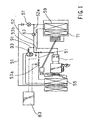
- a known air conditioning system is disclosed in Japanese Unexamined Patent Publication No. 7-19630 and includes a compressor 1, a cooling circuit 51, a heating circuit 52 and a controller 83, as shown in FIG. 1.
- the cooling circuit 51 includes a condenser 55, a first expansion valve 57 and a heat exchanger 59 provided on a passage connecting a discharge port D to a suction port S of the compressor 1. High temperature and high pressure refrigerant discharged from the discharge port D of the compressor 1 is drawn through the above respective devices and back to the compressor 1.
- the heating circuit 52 includes a bypass passage 52a that extends from the discharge port D of the compressor 1 to the heat exchanger 59, a second expansion valve 63 provided within the bypass passage 52a and the heat exchanger 59.
- the high-temperature and high-pressure refrigerant discharged from the compressor 1 is not directed to the condenser 55, but rather is drawn by the compressor 1 through the second expansion valve 63 and the heat exchanger 59.
- Such a heating circuit 52 is generally known as a hot gas bypass heater.
- the operation of the cooling circuit 51 and the heating circuit 52 is changeably selected by opening and closing selector valves 53a and 53b, which opening and closing operations are performed by the controller 83.
- the air conditioning system must operate in a high pressure state when the heating circuit 52 is utilized.
- An abnormally high-pressure state may be created if the output discharge capacity of the compressor 1 temporarily increases during the operation of the heating circuit 52.
- a refrigerant releasing passage 91 having a pressure relief valve 93 is provided in order to release excess pressure from heating circuit 52, if an abnormally high pressure state is reached.
- the refrigerant releasing passage 91 is connected to the heating circuit 52 and the cooling circuit 51 and the pressure relief valve 93 can be opened to release the refrigerant from the heating circuit 52 into the cooling circuit 51 when the refrigerant discharge pressure abnormally increases during the operation of the heating circuit 52.
- the refrigerant is released toward the cooling circuit 51 which is not used when the discharge pressure is increased abnormally during operation of the heating circuit 52, thereby preventing the discharge pressure at the heating circuit 52 from increasing abnormally.
- the refrigerant is released from the operating heating circuit 52 to the cooling circuit 51 which is not used, the abnormally high-pressure state of the discharge pressure during operation of the heating circuit 52 can be alleviated.
- the refrigerant in the heating circuit 52 is released into the cooling circuit 51 whenever the discharge pressure increases, the amount of the refrigerant in the heating circuit 52 is reduced and heating performance may be reduced.
- the high-pressure refrigerant is wastefully released from the heating circuit 52 by working the compressor 1, energy efficiency is reduced.
- an object of the present invention to provide an air conditioning system that can alleviate abnormal high pressure state without releasing the high-pressure refrigerant outside the heating circuit and without reducing the energy efficiency.
- an air conditioning system may include a compressor having a driving unit within the compressor driving chamber, a cooling circuit, a heating circuit and first and second capacity controllers.
- the air conditioning system may release high pressure refrigerant from the compressor discharge port into the compressor driving chamber by utilizing the capacity controllers.
- the driving unit may decrease the compressor output discharge capacity. As the result, the compressor discharge pressure will be decreased and the compressor suction pressure will be increased by the reduction in the compressor output discharge capacity.
- the first and the second capacity controllers are provided in parallel within the air conditioning system and each capacity controller may communicate the discharge port with the driving chamber respectively.
- the first capacity controller may communicate the discharge port with the driving chamber when compressor suction pressure results predetermined low-pressure state during operation of the cooling circuit. This is, when the compressor suction pressure results the predetermined low-pressure state during operation of the cooling circuit, high pressure refrigerant is released from the discharge port into the driving chamber.
- the driving unit decreases the compressor output discharge capacity, thereby increasing the suction pressure and preventing the heat exchanger from being frosted.
- the second capacity controller may communicate the discharge port with the driving chamber when compressor discharge pressure results predetermined high-pressure state during operation of the heating circuit.
- the driving unit decreases the compressor output discharge capacity, thereby decreasing the discharge pressure and preventing the heating circuit from being damaged by the abnormally high discharge pressure.
- the first capacity controller may communicate the discharge port with the driving chamber not only when compressor suction pressure results predetermined low-pressure state during operation of the cooling circuit but also when compressor discharge pressure results predetermined high-pressure state during operation of the heating circuit.
- both first and second capacity controllers provided in parallel within the air conditioning system may communicate the discharge port with the driving chamber. Therefore, high pressure refrigerant is swiftly released from the discharge port into the driving chamber and the pressure within the driving chamber quickly increases. As the result, the driving unit quickly decreases the compressor output discharge capacity and the abnormally high discharge pressure is quickly alleviated.
- an air conditioning system may include a compressor, a cooling circuit, a heating circuit and first and second controllers.
- the compressor may have a driving unit provided within a compressor driving chamber, a suction port for drawing refrigerant into the compressor and a discharge port for discharging high-pressure and high-temperature refrigerant from the compressor.
- the driving unit may decrease the compressor output discharge capacity when the pressure within the driving chamber increases.
- the cooling circuit may have a condenser and a heat exchanger provided on a passage that extends from the discharge port to the suction port.
- the heating circuit may have a passage that extends from the discharge port to the heat exchanger. This is, the heating circuit partially overlaps with the cooling circuit.
- Such type of the heating circuit is generally known as a hot gas bypass heater.
- a decompressor such as an expansion valve may be disposed onto the passage that extends from the discharge port to the heat exchanger in the hot gas bypass heater.
- the first and the second capacity controllers are provided in parallel within the air conditioning system. Each capacity controller may communicate the discharge port with the driving chamber. When the discharge port is communicated with the driving chamber, the high-pressure refrigerant is released from the discharge port into the driving chamber. As the result, the driving unit decreases the compressor output discharge capacity.
- the first capacity controller may communicate the discharge port with the driving chamber when compressor suction pressure results predetermined low-pressure state during operation of the cooling circuit.
- the high pressure refrigerant is released from the discharge port into the driving chamber.
- the driving unit decreases the compressor output discharge capacity and the suction pressure increases thereby preventing the heat exchanger from being frosted.
- the first capacity controller may have a first capacity control valve disposed within the first passage that connects the discharge port to the driving chamber. The first capacity control valve may open the first passage when compressor suction pressure results predetermined low-pressure state during operation of the cooling circuit for preventing the heat exchanger from being frosted.
- the first capacity control valve is one of the features that corresponds to the first capacity controller or to the first means for controlling the compressor output discharge capacity.
- the second capacity controller may communicate the discharge port with the driving chamber when compressor discharge pressure results predetermined high-pressure state during operation of the heating circuit.
- the high pressure refrigerant is released from the discharge port into the driving chamber.
- the second capacity controller may have a second capacity control valve provided in parallel with the first capacity control valve and disposed within the second passage that connects the discharge port to the driving chamber.
- the second capacity control valve may open the second passage when compressor discharge pressure results predetermined high-pressure state during operation of the heating circuit for alleviating the abnormally high discharge pressure.
- the second capacity control valve is one of the features that corresponds to the second capacity controller or to the second means for controlling the compressor output discharge capacity.
- the first capacity controller may communicate the discharge port with the driving chamber not only when compressor suction pressure results predetermined low-pressure state during operation of the cooling circuit but also when the compressor discharge pressure results predetermined high-pressure state during operation of the heating circuit.
- the second capacity controller may communicate the discharge port with the driving chamber when compressor discharge pressure results predetermined high-pressure state during operation of the heating circuit.
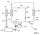
- the air conditioning system 100 may include a cooling circuit 151, a heating circuit 152 and a variable displacement compressor 101 as a driving source for both the heating and cooling circuits 151, 152.
- Representative first and second capacity controllers are shown in FIGS. 3, but are not shown in FIG. 2 for the sake of convenience and will be described below in further detail.
- Such an air conditioning system 100 may be utilized in a vehicle-mounted air conditioning system.
- the compressor driving shaft 125 may be coupled to and driven by an automobile engine 170.
- the cooling circuit 151 may be driven by high-pressure refrigerant, which is compressed by the compressor 101, and may include a condenser 155, a first expansion valve 157, a heat exchanger 159 and an accumulator 161. These devices may be disposed within a path 151a that extends from a discharge port D to a suction port S of the compressor 101.
- the heat exchanger 159 is also generally known as an evaporator.
- the heat exchanger 159 may be arranged side by side with a hot-water heater 171, which circulates hot coolant from the engine 170 through a pipe 173.
- the heating circuit 152 may be driven by high-temperature and high-pressure refrigerant, which is also compressed by the compressor 101, and may include a second expansion valve 163, the heat exchanger 159 and the accumulator 161. These devices are disposed on a bypass passage 152a for introducing the refrigerant discharged from the discharge port D to the heat exchanger 159. In other words, the heating circuit 152 partially overlaps with the cooling circuit 151.
- Such a heating circuit 152 is also generally known as a hot-gas bypass heater.
- a first open/close valve 153a and a second open/close valve 153b may be utilized as switch valves for alternatively actuating the cooling circuit 151 and the heating circuit 152.
- the refrigerant is compressed by the compressor 101 to attain a high-temperature and high-pressure state.
- This compressed refrigerant is sent to the condenser 155, where heat from the high-temperature refrigerant is dissipated to the outside environment and the refrigerant is liquefied.
- the refrigerant is decompressed by the first expansion valve 157 and sent to the heat exchanger 159 where the refrigerant absorbs outside heat and is gasified.
- the gasified refrigerant is returned to the compressor 101 again through the accumulator 161 for re-circulation throughout the system 100.
- the refrigerant is compressed by the compressor 101 to attain a high-temperature and high-pressure state.
- the compressed refrigerant is then decompressed by the second expansion valve 163 and sent to the heat exchanger 159, where heat from the compressed refrigerant is dissipated to the outside environment.
- the refrigerant is constantly in a gaseous state while circulating through the heating circuit 152.
- the heating circuit 152 may be used as an auxiliary heater. Heat generated by the heat exchanger 159 during operation of the heating circuit 152 may be used as an auxiliary heating source for the hot water heater 171. The heating circuit 152 also may be used to assist the coolant from the engine 170 when the coolant can not provide sufficient heat to start the engine 170 in a low-temperature environment, such as an outside air temperature of - 20 °C or so.
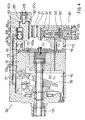
- a representative compressor 101 may include a driving chamber 110 defined within a housing 101a of the compressor 101 and a swash plate 130 that is rotatably supported by the driving shaft 125 in the driving chamber 110.
- the swash plate 130 may be supported by the driving shaft 125 and may rotate together with the driving shaft 125.
- the swash plate 130 is inclined with respect to the driving shaft 125 when the driving shaft 125 rotates and the inclination angle of the swash plate 130 with respect to a plane perpendicular to the axis of rotation of the driving shaft 125 is changeable.
- the peripheral edge portion of the swash plate 130 may be connected to the base portions of the pistons 135 by means of movable shoes 131.
- Six pistons 135 in total may be disposed around the driving shaft 125 (however, only one piston is shown in FIG. 3 for the sake of convenience) and may be laterally slide within six cylinder bores 109. The circumferential positions of the six cylinder bores 109 are fixed by the compressor housing 101a.
- a suction port 118a and a discharge port 123a are defined in a bottom portion of each the cylinder bore 109.
- a suction valve 118 is positioned to correspond to the suction port 118a and a discharge valve 123 is positioned to correspond to the discharge port 123a.
- Each suction port 118a communicates with a suction chamber 115 and each the discharge port 123a communicates with a discharge chamber 120.
- the output discharge capacity of the compressor 101 is determined by the stroke length of the piston 135, which is determined by the degree of change in inclination angle of the swash plate 130 during each cycle. That is, the further the swash plate 130 is withdrawn from the cylinder bore 109 during each cycle, the longer the stroke length of the piston 135 will be. As the stroke length increases, the output discharge capacity of the compressor 101 also increases.
- the inclination angle of the swash plate 130 is determined, in part, by the difference in pressure on the opposite sides of the piston 135, i.e., the pressure difference between driving chamber pressure and the cylinder bore pressure. Increasing or decreasing the driving chamber pressure can adjust this pressure difference.
- the driving chamber 110 is connected to the suction chamber 115 through the bleeding passage 105. Although it is not particularly shown in FIG.3, a throttle is provided in the bleeding passage 105.
- the high-pressure refrigerant is released from the discharge chamber 120 into the driving chamber 110. Due to resulting increase in the driving chamber pressure, the swash plate 130 stands and the stroke length of the piston 135 decreases. Therefore, the output discharge capacity also will decrease.
- the refrigerant in the discharge chamber 120 is prevented from being released into the driving chamber 110. As the result, the pressure within the driving chamber 110 will gradually decrease, the swash plate 130 will move further in the lateral direction and the stroke length of the piston 135 will increase. In this case, the output discharge capacity will increase.
- the compressor 101 includes a heating circuit capacity controller 401 and a cooling circuit capacity controller 301.
- Each controller 301, 401 may communicate the discharge chamber 120 with the driving chamber 110 respectively.
- the discharge chamber 120 is connected to the driving chamber 110 by a first heating circuit capacity control passage 421 and a second heating circuit capacity control passage 422. Further, the discharge chamber 120 is connected to the driving chamber 110 by a first cooling circuit capacity control passage 321 and a second cooling circuit capacity control passage 322.
- a heating circuit capacity control valve 403 is provided between the first and second heating circuit capacity control passages 421, 422.
- a cooling circuit capacity control valve 303 is provided between the first and second cooling circuit capacity control passages 321, 322.
- the heating circuit capacity control valve 403 includes a first chamber 405 that is communicated with the discharge chamber 120 by the first heating circuit capacity control passage 421 and a second chamber 407 that is communicated with the driving chamber 110 by the second heating circuit capacity control passage 422. Therefore, the pressure within the first chamber 405 is equal to the compressor discharge pressure Pd and the pressure within the second chamber 407 is equal to the pressure Pc within the driving chamber 110.
- the first and second chambers 405, 407 can be communicated with each other by opening the heating circuit capacity control valve 403 when the pressure within the first chamber 405 (equal to the discharge pressure Pd) increases with respect to the pressure within the second chamber 407 (equal to the pressure Pc within the driving chamber 110), because a valve body 409 moves to communicate the first chamber 405 with the second chamber 407.
- the first and second chambers 405, 407 are not communicated in a normal operation of the compressor, because the valve body 409 cuts the communication between the first and second chambers 405, 407.
- the valve body 409 is biased by a spring 409a such that the valve body 409 cuts the communication between the first and second chamber 405, 407.
- valve body 409 is integrally connected with an actuating member 413 by means of a connecting member 411.
- the actuating member 413 may be biased by exciting a solenoid 415 such that the reference pressure for opening the heating circuit capacity control valve 403 may be changed by controlling the biasing force exerted by the solenoid 415 onto the actuating member 413.
- the solenoid 415 is excited by a control signal of a controller (not particularly shown in FIG. 3). When the solenoid 415 is excited, the biasing force to open the heating circuit capacity control valve 403 is exerted onto the valve body 409.
- the biasing force exerted onto the valve body 409 by the spring 409a to close the heating circuit capacity control valve 403 and the biasing force exerted onto the valve body 409 by the solenoid 415 to open the heating circuit capacity control valve 403 defines the reference pressure for opening the heating circuit capacity control valve 403.
- the cooling circuit capacity control valve 303 includes a valve body 305 and a bellows 315 that is provided within a suction pressure detecting chamber 315a.
- the compressor suction pressure Ps is introduced from the suction chamber 116 to the suction pressure detecting chamber 315a through a suction pressure detecting passage 313.
- the bellows 315 can expand or contract based on the suction pressure Ps for moving the valve body 305 to open or to close the cooling circuit capacity control valve 303.
- the first and second cooling circuit capacity control passages 321, 322 may be communicated with each other by opening the cooling circuit capacity control valve 303 when the suction pressure Ps within the suction pressure detecting chamber 315a results predetermined low-pressure state.
- the valve body 305 is connected with an actuating member 307 by means of a connecting member 311.
- the actuating member 307 is biased by exciting or not exciting a solenoid 309 such that the reference pressure for opening the cooling circuit capacity control valve 303 may be changed by controlling the biasing force exerted by the solenoid 309 onto the actuating member 307. This is, the biasing force exerted by the solenoid 309 onto the valve body 305 defines the reference pressure for opening the cooling circuit capacity control valve 303.
- the solenoid 309 is excited by a control signal of a controller (not particularly shown in FIG. 3).
- the heating circuit capacity control valve 403 is closed when the compressor discharge pressure Pd does not result predetermined high-pressure state. Because the difference between the discharge pressure Pd within the first chamber 405 and the pressure Pc within the second chamber 407 does not increase to move the valve body 409. Thus, the first and second heating circuit capacity control passages 421, 422 are not communicated with each other. Therefore, the high-pressure refrigerant within the discharge chamber 120 is not released into the driving chamber 110. As the result, the pressure Pc within the driving chamber 110 is not increased, the compressor output discharge capacity is not decreased and the discharge pressure Pd is not decreased thereby maintaining the heating circuit operation performance at high.
- the heating circuit capacity control valve 403 is opened when the compressor discharge pressure Pd results predetermined high-pressure state. Because the difference between the discharge pressure Pd within the first chamber 405 and the pressure Pc within the second chamber 407 increases enough to prevail over the biasing force of the spring 409a and to move the valve body 409 to open the heating circuit capacity control valve 403. Thus, the first and second heating circuit capacity control passages 421, 422 are communicated with each other. As the result, the high-pressure refrigerant within the discharge chamber 120 is released into the driving chamber 110. The pressure Pc within the driving chamber 110 is increased, the compressor output discharge capacity is decreased and the discharge pressure Pd is decreased thereby alleviating the abnormally high discharge pressure.
- the cooling circuit capacity control valve 303 is closed when the suction pressure Ps does not result predetermined low-pressure state.
- the first and second cooling circuit capacity control passages 321, 322 are not communicated with each other. Therefore, the high-pressure refrigerant within the discharge chamber 120 is not released into the driving chamber 110.
- the pressure Pc within the driving chamber 110 is not increased, the compressor output discharge capacity is not decreased and the discharge pressure Pd is not decreased thereby maintaining the cooling circuit operating performance at high.
- the cooling circuit capacity control valve 303 is opened when the suction pressure Ps results predetermined low-pressure state.
- the first and second cooling circuit capacity control passages 321, 322 are communicated with each other. Therefore, the high-pressure refrigerant within the discharge chamber 120 is released into the driving chamber 110.
- the pressure Pc within the driving chamber 110 is increased, the compressor output discharge capacity is decreased and the suction pressure Ps is increased, thereby preventing the cooling circuit heat exchanger from being frosted.
- the cooling circuit capacity control valve 303 is always to be closed because the compressor output discharge capacity is to be controlled exclusively by utilizing the heating circuit capacity control valve 403. Therefore, the reference pressure for opening the cooling circuit capacity control valve 303 is set Lower than the suction pressure during the operation of the heating circuit 152. As described above, the reference pressure for opening the cooling circuit capacity control valve 303 may be changed by utilizing the solenoid 309. In such state, the suction pressure Ps during the operation of the heating circuit 152 does not meet the condition for opening the cooling circuit capacity control valve 303. As the result, the cooling circuit capacity control valve 303 is always closed during the operation of the heating circuit 152.
- the heating circuit capacity control valve 403 is always to be closed because the compressor output discharge capacity is to be controlled exclusively by utilizing the cooling circuit capacity control valve 303. Therefore, the reference pressure for opening the heating circuit capacity control valve 403 is set higher than the discharge pressure during the operation of the cooling circuit 151. As described above, the reference pressure for opening the heating circuit capacity control valve 403 may be changed by utilizing the solenoid 415. In such state, the discharge pressure Pd during the operation of the cooling circuit 151 does not meet the condition for opening the heating circuit capacity control valve 403. As the result, the heating circuit capacity control valve 403 is always closed during the operation of the cooling circuit 151.
- energy efficiency is slightly decreased because the compressor 101 releases the compressed refrigerant from the discharge chamber 120 into the driving chamber 110 by utilizing the first or the second capacity controllers 301, 401.
- the output discharge capacity of the compressor 101 is decreased by releasing a small amount of the refrigerant. Therefore, the reduction of energy efficiency for controlling the compressor output discharge capacity can be minimized.
- Second representative embodiment is regarding a quick alleviation of the abnormally high discharge pressure during operation of the heating circuit. Because the devices utilized in the second representative embodiment are substantially the same with the corresponding devices utilized in the first representative embodiment, FIGS. 2, 3 are used in describing the second representative embodiment.
- the heating circuit capacity control valve 403 when the compressor discharge pressure results predetermined high-pressure state during the operation of the heating circuit 152, the heating circuit capacity control valve 403 communicates the first heating circuit capacity control passage 421 with the second heating circuit capacity control passage 422 and, at the same time, the cooling circuit capacity control valve 303 communicates the first cooling circuit capacity control passage 321 with the second cooling circuit capacity control passage 322.
- the heating circuit capacity controller 401 communicates the discharge chamber 120 with the driving chamber 110 and the cooling circuit capacity controller 301 also communicates the discharge chamber 120 with the driving chamber 110 when the compressor discharge pressure results abnormally high during the operation of the heating circuit 152.
- the reference pressure for opening the heating circuit capacity control valve 403 is set by utilizing the solenoid 415 as the predetermined value of the discharge pressure. Further, the reference pressure for opening the cooling circuit capacity control valve 303 is set lower than the suction pressure Ps during the operation of the heating circuit 152. The reference pressure for opening the cooling circuit capacity control valve 303 may be changed by utilizing the solenoid 309. In such state, the suction pressure Ps during the operation of the heating circuit 152 does not meet the condition for opening the cooling circuit capacity control valve 303. As the result, the cooling circuit capacity control valve 303 is closed during the operation of the heating circuit.
- the discharge pressure Pd increases in comparison with the pressure Pc within the driving chamber 110 thereby moving the valve body 409 to open the heating circuit capacity control valve 403.
- the reference pressure for opening the cooling circuit capacity control valve 303 is changed, for example, by making the reference pressure for opening the cooling circuit capacity control valve 303 exceed the upper value of the suction pressure Ps in operating the heating circuit 152 or by stopping the exertion of the biasing force of the solenoid 309 onto the valve body 305.
- the cooling circuit capacity control valve 303 When the reference pressure of the cooling circuit capacity control valve 303 is set to exceed the upper value of the suction pressure Ps in operating the heating circuit, the cooling circuit capacity control valve 303 is opened because the suction pressure Ps in operating the heating circuit meets the condition for opening the cooling circuit capacity control valve 303.
- high-pressure refrigerant within the discharge chamber 120 is released into the driving chamber 110 not only through the first and second heating circuit capacity control passages 421,422 but also through the first and second cooling circuit capacity control passages 321, 322. Therefore, the pressure within the driving chamber 110 increases quickly by the high-pressure refrigerant released from the discharge chamber by two passages, i.e., the heating circuit capacity control passages 421, 422 and the cooling circuit capacity control passages 321, 322.
- the swash plate 130 quickly stands, piston-stroke decreases, compressor output discharge capacity decreases and the abnormally high discharge pressure is alleviated quickly.
- the refrigerant released into the driving chamber 110 is drawn into the cylinder bores 109 through the bleeding passage 501, the suction chamber 115, the suction port 118a and the suction valve 118 and then re-compressed and discharged through the discharge port 123a, the discharge valve 123, the discharge chamber 120 and the discharge opening 121.
- the reference pressure for opening the cooling circuit capacity control valve 303 is set by utilizing the solenoid 309 as the predetermined value of the suction pressure. Further, the reference pressure for opening the heating circuit capacity control valve 403 is set higher than the discharge pressure Pd during the operation of the cooling circuit 151. The reference pressure for opening the heating circuit capacity control valve 403 may be changed by utilizing the solenoid 415. In such state, the discharge pressure Pd during the operation of the cooling circuit does not meet the condition for opening the heating circuit capacity control valve 403. As the result, the heating circuit capacity control valve 403 is always closed during the operation of the cooling circuit 151.
- the bellows 315 moves the valve body 305 to open the cooling circuit capacity control valve 303.
- the first and second cooling circuit capacity control passages 321, 322 communicate with each other, thereby releasing the high-pressure refrigerant from the discharge chamber 120 into the driving chamber 110.
- the pressure within the driving chamber 110 increases, the output discharge capacity decreases and the suction pressure increases to prevent the heat exchanger of the cooling circuit 151 from being frosted.
- a problem of shortage of heating performance due to release of the refrigerant in the heating circuit into the cooling circuit does not occur.
- the heating circuit capacity control valve 403 but also the cooling circuit capacity control valve 303 may be utilized for releasing the high-pressure refrigerant from the discharge chamber 120 into the driving chamber 110, the refrigerant can quickly be released for alleviating the abnormally high discharge pressure during operation of the heating circuit 152.
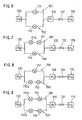
- a heating circuit capacity controller 601 includes a heating circuit capacity control valve 603 and a pilot valve 619 as shown in Fig. 4.
- the heating circuit capacity control valve 603 includes a first chamber 605 and a second chamber 607 communicated or not communicated with the first chamber 605 by a valve body 609.
- the valve body 609 is biased by a spring 609a to close the heating circuit capacity control valve 603.
- the first chamber 605 is connected with the discharge chamber 120 by a first heating circuit capacity control passage 621. Therefore, the pressure within the first chamber 605 is equal to the discharge pressure Pd.
- the second chamber 607 is connected to the driving chamber 110 by a second heating circuit capacity control passage 422.
- the pressure within the second chamber 607 is equal to the pressure Pc within the driving chamber 110.
- the heating circuit capacity control valve 603 is opened or closed based on a difference between the pressure within the first chamber 605 and the pressure within the second chamber 607.
- the valve body 609 is moved by such difference to open the heating circuit capacity control valve 603.
- the valve body 609 can not be moved because the difference in pressures does not prevail over the biasing force of the spring 609a. In such case, the heating circuit capacity control valve 603 is closed.
- the pilot valve 619 is disposed upstream of the heating circuit capacity control valve 603 on the first heating circuit capacity control passage 621.
- the pilot valve 619 opens or closes the first heating circuit capacity control passage 621 by means of a solenoid 615.
- Structures of another devices utilized in the third representative embodiment are substantially the same with the structures of the respective devices utilized in the first representative embodiment. Therefore, detailed description is omitted for the sake of convenience with respect to such structures.
- the output discharge capacity of the compressor 701 is to be controlled exclusively by opening or closing the cooling circuit capacity control valve 301. Therefore, the heating circuit capacity control valve 603 is to be closed all the time during the operation of the cooling circuit.
- the heating circuit capacity control valve 603 is constructed to open based on the difference between the discharge pressure Pd within the first chamber 605 and the pressure Pc within the second chamber 607. Thus, the heating circuit capacity control valve 603 may possibly be opened when the discharge pressure Pd is much increased by chance. Therefore, the pilot valve 619 closes the first heating circuit capacity control passage 621 in order not to make the high-pressure refrigerant introduced to the first chamber 605 through an upstream passage 621a and a downstream passage 621b. Thus, the pilot valve 619 cuts the communication between the discharge chamber 120 and the first chamber 605 in the heating circuit capacity control valve 603 all the time during the operation of the cooling circuit.
- the output discharge capacity of the compressor 701 is to be controlled exclusively by opening or closing the heating circuit capacity control valve 603. Therefore, the pilot valve 619 opens the first heating circuit capacity control passage 621 to introduce the refrigerant from the discharge chamber 120 to the first chamber 605 in the heating circuit capacity control valve 603.
- the pressure Pd within the first chamber 605 moves the valve body 609 against the biasing force of the spring 609a to open the heating circuit capacity control valve 603.
- the heating circuit capacity control valve 603 By opening the heating circuit capacity control valve 603, the high-pressure refrigerant is released from the discharge chamber 120 into the driving chamber 110 thereby alleviating the abnormally high discharge pressure.
- the cooling circuit capacity control valve 303 may be closed for controlling the compressor output discharge capacity exclusively by means of the heating circuit capacity controller 601.
- the cooling circuit capacity control valve 303 may be opened by changing the reference pressure thereof such that the high-pressure refrigerant within the discharge chamber 120 can be released into the driving chamber 110 by utilizing both the heating circuit capacity controller 601 and the cooling circuit capacity controller 301. In latter case, the abnormally high discharge pressure can be alleviated quickly.
- a heating circuit capacity controller 801 includes a heating circuit capacity control valve 803 that is opened or closed based on the difference of pressure within a first chamber 805 and a pressure within a second chamber 807.
- the first chamber 805 is connected with the discharge chamber 120 through the first heating circuit capacity control passage 821. Therefore, the pressure within the first chamber 805 is equal to the discharge pressure Pd.
- the second chamber 807 is connected with the driving chamber 110 through the second heating circuit capacity control passage 422. Therefore, the pressure within the second chamber 807 is equal to the pressure Pc within the driving chamber110.
- pilot valve as described in the third representative embodiment is omitted in the fourth representative embodiment.
- the output discharge capacity of the compressor 800 is to be controlled exclusively by opening or closing a cooling circuit capacity control valve 301 that has substantially the same constructions as utilized in the third representative embodiment. Therefore, the heating circuit capacity control valve 803 is to be closed all the time during the operation of the cooling circuit. However, the heating circuit capacity control valve 803 is constructed to be opened based on a difference between the discharge pressure Pd within the first chamber 805 and the pressure Pc within the second chamber 807. Thus, the heating circuit capacity control valve 803 may possibly be opened when the discharge pressure Pd is much increased by chance.
- the heating circuit capacity control valve 803 is opened by chance during the operation of the cooling circuit, the compressor discharge pressure is decreased because high-pressure refrigerant within the discharge chamber 120 is released into the driving chamber 110, pressure within the driving chamber 110 increases, piston-stroke of the compressor 800 decreases and the compressor output discharge capacity decreases.
- the pressure Pd within the first chamber 805 decreases.
- pressure difference between the pressure Pd within the first chamber 805 and the pressure Pc within the second chamber 807 can no more prevail over the biasing force of a spring 809a.
- the heating circuit capacity control valve 803 will soon be closed. Therefore, the heating circuit capacity controller 801 that does not include a pilot valve causes no practical damage onto the air conditioning system.
- the heating circuit capacity controller and the cooling circuit capacity controller are provided in parallel within the air conditioning system such that each capacity controller may independently communicate the compressor discharge chamber with the compressor driving chamber.
- a capacity control valve that is opened based on a pressure difference or a capacity control valve that is opened based on an outside signal may preferably employed to the heating circuit capacity controller and to the cooling circuit capacity controller.
- the valve may be opened based on the discharge pressure and another pressure lower than the discharge pressure such like a suction pressure, pressure within the driving chamber, atmospheric pressure or vacuum pressure.
- the valve may be opened based on the suction pressure and the pressure other than the suction pressure such like the pressure within the driving chamber, atmospheric pressure or vacuum pressure.
- the valve may be opened based on the outside signal that is generated in response to an absolute value of the pressure such like the discharge pressure or the suction pressure.
- several types of compressor output discharge capacity control techniques may be constructed.
- Fig. 6 shows one of such types in which the capacity control valves that are opened based on the outside signals are employed both to the cooling circuit capacity controller 701 and to the heating circuit capacity controller 702.
- Such capacity control valves 711, 712 are disposed in parallel on a passages extending from the discharge chamber 120 to the driving chamber 110.
- the driving chamber 110 is connected to the suction chamber 115.
- a throttle 731 is disposed between the driving chamber 110 and the suction chamber 115.
- high-pressure refrigerant within the discharge chamber 120 is released into the driving chamber 110 through the cooling circuit capacity control valve 711 that is opened by the outside signal, thereby preventing the heat exchanger in the cooling circuit from being frosted.
- high-pressure refrigerant within the discharge chamber 120 may be quickly released into the driving chamber 110 through both the cooling circuit capacity control valve 711 and the heating circuit capacity control valve 712, when the discharge pressure Pd results abnormally high-pressure state during operation of the heating circuit, thereby quickly alleviating the abnormally high discharge pressure in operating the heating circuit.
- the refrigerant released into the driving chamber 110 is retained within the driving chamber 110 relatively for long time, because the throttle 731 prevents the refrigerant from being released swiftly from the driving chamber 110 into the suction chamber 115. Therefore, high-pressure state within the driving chamber 110 can be maintained relatively for long time, thereby decreasing the compressor output discharge capacity effectively.
- a cooling circuit capacity controller 701 may include a cooling circuit capacity control valve 711 that is opened based on a difference between the compressor suction pressure Ps and another pressure.
- a pilot valve 711a is disposed upstream of the cooling circuit capacity control valve 711 on the passage extending from the discharge chamber 120 to the driving chamber 110. The pilot valve 711a is opened or closed by utilizing a solenoid that is not shown in the drawings.
- a heating circuit capacity controller 702 is provided in parallel with the cooling circuit capacity controller 701 and may include a heating circuit capacity control valve 712 that is opened based on an outside signal. During operation of the cooling circuit, the pilot valve 711a is opened, at least when the compressor suction pressure Ps results predetermined low-pressure state.
- the refrigerant within the discharge chamber 120 is introduced to the cooling circuit capacity control valve 711.
- the predetermined low suction pressure increases the pressure difference and opens the cooling circuit capacity control valve 711.
- high-pressure refrigerant within the discharge chamber 120 is released into the driving chamber 110 through the pilot valve 711a and through the cooling circuit capacity control valve 711, thereby decreasing the compressor output discharge capacity, increasing the suction pressure and preventing the heat exchanger in the cooling circuit from being frosted.
- high-pressure refrigerant within the discharge chamber 120 is released into the driving chamber 110 through the heating circuit capacity control valve 712 that is opened by the outside signal, thereby decreasing the compressor output discharge capacity and alleviating the abnormally high discharge pressure.
- high-pressure refrigerant within the discharge chamber 120 may be quickly released into the driving chamber 110 through both the cooling circuit capacity control valve 711 and the heating circuit capacity control valve 712, when the discharge pressure results abnormally high-pressure state during operation of the heating circuit, thereby quickly alleviating the abnormally high discharge pressure in operating the heating circuit.
- the refrigerant released into the driving chamber 110 is retained within the driving chamber 110 relatively for long time because the throttle 731 prevents the refrigerant from being released swiftly from the driving chamber 110 into the suction chamber 115. Therefore, the high-pressure state within the driving chamber 110 can be maintained relatively for long time, thereby effectively decreasing the compressor output discharge capacity.
- a cooling circuit capacity controller 701 may include a cooling circuit capacity control valve 711 that is opened based on an outside signal.
- a heating circuit capacity controller 702 is provided in parallel with the cooling circuit capacity controller 701 and may include a heating circuit capacity control valve 712 that is opened based on a difference between the compressor discharge pressure Pd and another pressure.
- a pilot valve 712a is disposed upstream of the heating circuit capacity control valve 712 on the passage extending from the discharge chamber 120 to the driving chamber 110. The pilot valve 712a is opened or closed by utilizing a solenoid that is not shown in the drawings. During operation of the heating circuit, the pilot valve 712a is opened, at least when the discharge pressure Pd results abnormally high.
- the refrigerant within the discharge chamber 120 is introduced to the heating circuit capacity control valve 712.
- the abnormally high discharge pressure increases the pressure difference and opens the heating circuit capacity control valve 712.
- high-pressure refrigerant within the discharge chamber 120 is released into the driving chamber 110 through the pilot valve 712a and through the heating circuit capacity control valve 712, thereby alleviating the abnormally high discharge pressure in operating the heating circuit.
- the suction pressure Ps results predetermined low-pressure state during operation of the cooling circuit
- high-pressure refrigerant within the discharge chamber 120 is released into the driving chamber 110 through the cooling circuit capacity control valve 711 that is opened by the outside signal, thereby preventing the heat exchanger in the cooling circuit from being frosted.
- high-pressure refrigerant within the discharge chamber 120 may be quickly released into the driving chamber 110 through both the cooling circuit capacity control valve 711 and the heating circuit capacity control valve 712 when the discharge pressure Pd results abnormally high-pressure state during operation of the heating circuit, thereby quickly alleviating the abnormally high discharge pressure in operating the heating circuit.
- the refrigerant released into the driving chamber 110 is retained within the driving chamber 110 relatively for long time because the throttle 731 prevents the refrigerant from being released swiftly from the driving chamber 110 into the suction chamber 115. Therefore, the high-pressure state within the driving chamber 110 can be maintained relatively for long time, thereby effectively decreasing the compressor output discharge capacity.
- a cooling circuit capacity controller 701 may include a cooling circuit capacity control valve 711 that is opened based on a difference between the compressor suction pressure Ps and another pressure.
- a pilot valve 711a is disposed upstream of the cooling circuit capacity control valve 711 on the passage extending from the discharge chamber 120 to the driving chamber 110. The pilot valve 711a is opened or closed by utilizing a solenoid that is not shown in the drawings.
- a heating circuit capacity controller 702 is provided in parallel with the cooling circuit capacity controller 701 and may include a heating circuit capacity control valve 712 that is opened based on a difference between the compressor discharge pressure Pd and another pressure.
- a pilot valve 712a is disposed upstream of the heating circuit capacity control valve 712 on the passage extending from the discharge chamber 120 to the driving chamber 110.
- the pilot valve 712a is opened or closed by utilizing a solenoid that is not shown in the drawings.
- the pilot valve 711a is opened, at least when the suction pressure Ps results predetermined low-pressure state.
- the predetermined low suction pressure increases the pressure difference and opens the cooling circuit capacity control valve 711.
- high-pressure refrigerant within the discharge chamber 120 is released into the driving chamber 110 through the pilot valve 711a and through the cooling circuit capacity control valve 711, thereby increasing the suction pressure and preventing the heat exchanger in the cooling circuit from being frosted.
- the pilot valve 712a is opened, at least when the discharge pressure results abnormally high-pressure state.
- the refrigerant within the discharge chamber 120 is introduced to the heating circuit capacity control valve 712.
- the abnormally high discharge pressure increases the pressure difference and opens the heating circuit capacity control valve 712.
- high-pressure refrigerant within the discharge chamber 120 is released into the driving chamber 110 through the pilot valve 712a and through the heating circuit capacity control valve 712, thereby alleviating the abnormally high discharge pressure in operating the heating circuit.
- high-pressure refrigerant within the discharge chamber 120 may be quickly released into the driving chamber 110 through both the cooling circuit capacity controller 701 and the heating circuit capacity controller 702, when the discharge pressure results abnormally high-pressure state during operation of the heating circuit, thereby quickly alleviating the abnormally high discharge pressure in operating the heating circuit.
- the capacity control valve may preferably be opened based on a value related to change in the discharge pressure.
- a one-time (discharge pressure increasing speed) or a multiple-time differential value such as a two-times differential value (discharge pressure increasing acceleration) can be utilized. It is determined that the discharge pressure will not increase drastically when, for example, the discharge pressure increasing speed (one-time differential value of the discharge pressure) does not exceed the predetermined value. And it is determined that the discharge pressure will increase drastically when the discharge pressure increasing speed exceeds the predetermined value. Therefore, it is possible to control the opening of the capacity control valve in response to the discharge pressure increasing speed.
- the cooling circuit capacity control valve and the heating circuit capacity control valve are disposed within the housing of the compressor.
- these devices can be provided outside the compressor in part or in whole.
- a one-sided swash plate type of compressor i.e., a compressor having pistons 135 disposed on only one side of the swash plate 130 in Fig.3, is utilized as the variable displacement compressor in above-described representative embodiments.
- a double-ended piston type can also be utilized in the variable displacement compressor, in which pistons are connected to opposite sides of the swash plate for reciprocation.
- driving chamber decompression means that releases the refrigerant from the driving chamber 110 in Fig.3 into the suction area (suction chamber 115, suction port 118a or suction opening 116) separately from the bleeding passage 501 when the driving chamber 110 is brought into a predetermined high-pressure state.
- the driving chamber decompression means may preferably have a passage extending from the driving chamber 110 to the suction area and a driving chamber decompression valve provided on the passage. The driving chamber decompression valve is opened when the driving chamber is brought into the predetermined high-pressure state in order to release the high-pressure refrigerant from the driving chamber 110 to the suction area to thereby prevent the airtight seal of the driving chamber 110 from being degraded.
- means for releasing the refrigerant directly from the discharge area (discharge chamber 120 or discharge opening 121) into the suction area may preferably be provided.
- the refrigerant releasing means may preferably have a passage extending from the discharge area to the suction area and a refrigerant releasing valve provided on the passage.
- the refrigerant releasing valve is opened when the discharge pressure is extremely increased such that the normal control by decreasing the compressor discharge capacity can not alleviate the extreme increase in the discharge pressure. Therefore, such means can be utilized as an emergent releasing means for decreasing the abnormally high-pressure state of the refrigerant.
- -An air conditioning system 100 may include a compressor 101 having a driving chamber 110, a cooling circuit 151, a heating circuit 152 and capacity controllers 301, 401.
- the compressor 101 may have a suction port 115, a discharge port 120, a driving unit 130 provided within the driving chamber 110.
- the driving unit 130 decreases compressor output discharge capacity when pressure within the driving chamber 110 increases.
- the first capacity controller 301 and the second capacity controller 401 are provided in parallel. Each capacity controller may communicate the discharge port 120 with the driving chamber 110 respectively.
- This system may release high-pressure refrigerant from the discharge port 120 into the driving chamber 110 when compressor suction pressure results predetermined low-pressure state during operation of the cooling circuit.
- the heat exchanger in the cooling circuit 151 is prevented from being frosted.
- the system may release high pressure refrigerant from the discharge port 120 into the driving chamber 110 when compressor discharge pressure results predetermined high-pressure state during operation of the heating circuit.
- the heating circuit 152 is prevented from being damaged by an abnormally high discharge
Applications Claiming Priority (4)
| Application Number | Priority Date | Filing Date | Title |
|---|---|---|---|
| JP583299 | 1999-01-12 | ||
| JP11005832A JP2000205667A (ja) | 1999-01-12 | 1999-01-12 | 空調装置 |
| JP11008075A JP2000205668A (ja) | 1999-01-14 | 1999-01-14 | 空調装置 |
| JP807599 | 1999-01-14 |
Publications (2)
| Publication Number | Publication Date |
|---|---|
| EP1020692A2 true EP1020692A2 (fr) | 2000-07-19 |
| EP1020692A3 EP1020692A3 (fr) | 2002-01-16 |
Family
ID=26339844
Family Applications (1)
| Application Number | Title | Priority Date | Filing Date |
|---|---|---|---|
| EP00100485A Withdrawn EP1020692A3 (fr) | 1999-01-12 | 2000-01-11 | Systèmes de conditionnement d'air |
Country Status (1)
| Country | Link |
|---|---|
| EP (1) | EP1020692A3 (fr) |
Cited By (2)
| Publication number | Priority date | Publication date | Assignee | Title |
|---|---|---|---|---|
| EP1020693A3 (fr) * | 1999-01-12 | 2002-01-16 | Kabushiki Kaisha Toyoda Jidoshokki Seisakusho | Systèmes de conditionnement d'air |
| CN101416003B (zh) * | 2006-04-06 | 2010-12-15 | 三电有限公司 | 空调装置 |
Citations (1)
| Publication number | Priority date | Publication date | Assignee | Title |
|---|---|---|---|---|
| JPH0719630A (ja) | 1993-07-02 | 1995-01-20 | Nippondenso Co Ltd | 空調装置 |
Family Cites Families (7)
| Publication number | Priority date | Publication date | Assignee | Title |
|---|---|---|---|---|
| JP2945748B2 (ja) * | 1990-11-16 | 1999-09-06 | サンデン株式会社 | 容量可変型揺動式圧縮機 |
| DE69200356T2 (de) * | 1991-01-28 | 1995-02-16 | Sanden Corp | Schiefscheibenverdichter mit einer Vorrichtung zur Hubveränderung. |
| JP3237187B2 (ja) * | 1991-06-24 | 2001-12-10 | 株式会社デンソー | 空調装置 |
| JP3292337B2 (ja) * | 1993-11-02 | 2002-06-17 | 株式会社豊田自動織機 | クラッチレス片側可変容量型圧縮機 |
| DE69834512T2 (de) * | 1997-07-31 | 2007-04-26 | Denso Corp., Kariya | Kühlkreisvorrichtung |
| JP2000111179A (ja) * | 1998-10-05 | 2000-04-18 | Toyota Autom Loom Works Ltd | 空調装置 |
| JP2000205666A (ja) * | 1999-01-12 | 2000-07-28 | Toyota Autom Loom Works Ltd | 空調装置 |
-
2000
- 2000-01-11 EP EP00100485A patent/EP1020692A3/fr not_active Withdrawn
Patent Citations (1)
| Publication number | Priority date | Publication date | Assignee | Title |
|---|---|---|---|---|
| JPH0719630A (ja) | 1993-07-02 | 1995-01-20 | Nippondenso Co Ltd | 空調装置 |
Cited By (3)
| Publication number | Priority date | Publication date | Assignee | Title |
|---|---|---|---|---|
| EP1020693A3 (fr) * | 1999-01-12 | 2002-01-16 | Kabushiki Kaisha Toyoda Jidoshokki Seisakusho | Systèmes de conditionnement d'air |
| CN101416003B (zh) * | 2006-04-06 | 2010-12-15 | 三电有限公司 | 空调装置 |
| US8117858B2 (en) | 2006-04-06 | 2012-02-21 | Sanden Corporation | Air conditioner |
Also Published As
| Publication number | Publication date |
|---|---|
| EP1020692A3 (fr) | 2002-01-16 |
Similar Documents
| Publication | Publication Date | Title |
|---|---|---|
| US6263687B1 (en) | Air conditioning systems | |
| US4606705A (en) | Variable displacement compressor control valve arrangement | |
| US4669272A (en) | Variable displacement refrigerant compressor of variable angle wobble plate type | |
| US6293117B1 (en) | Air conditioning system | |
| EP1172562B1 (fr) | Compresseur à spirales | |
| US5071321A (en) | Variable displacement refrigerant compressor passive destroker | |
| US6247322B1 (en) | Air conditioning systems | |
| EP1994278B1 (fr) | Distributeur a tiroir avec orifice de derivation des gaz chauds | |
| US6595015B2 (en) | Air conditioning systems | |
| US8272846B2 (en) | Integral slide valve relief valve | |
| US6212893B1 (en) | Air conditioning systems | |
| US6250094B1 (en) | Air conditioning systems | |
| US20010024616A1 (en) | Variable displacement type compressor with suction control valve | |
| US20020104327A1 (en) | Vehicular air conditioner | |
| EP1020692A2 (fr) | Systèmes de conditionnement d'air | |
| EP1014016A2 (fr) | Systèmes de conditionnement d'air | |
| US4890985A (en) | Air conditioning system with variable capacity compressor | |
| EP1001230A2 (fr) | Systèmes de conditionnement d'air | |
| JP3936439B2 (ja) | 空調装置の可変容量型圧縮機用制御弁 | |
| JP2002061571A (ja) | 容量可変型斜板式圧縮機 | |
| JP3187587B2 (ja) | 車両用空調装置 | |
| JP4118413B2 (ja) | 容量可変斜板式コンプレッサ | |
| JPH06229636A (ja) | 車両用空調装置 | |
| JPS6291672A (ja) | 可変容量圧縮機 | |
| US7874813B2 (en) | Variable displacement compressor |
Legal Events
| Date | Code | Title | Description |
|---|---|---|---|
| PUAI | Public reference made under article 153(3) epc to a published international application that has entered the european phase |
Free format text: ORIGINAL CODE: 0009012 |
|
| 17P | Request for examination filed |
Effective date: 20000111 |
|
| AK | Designated contracting states |
Kind code of ref document: A2 Designated state(s): DE FR IT Kind code of ref document: A2 Designated state(s): AT BE CH CY DE DK ES FI FR GB GR IE IT LI LU MC NL PT SE |
|
| AX | Request for extension of the european patent |
Free format text: AL;LT;LV;MK;RO;SI |
|
| PUAL | Search report despatched |
Free format text: ORIGINAL CODE: 0009013 |
|
| AK | Designated contracting states |
Kind code of ref document: A3 Designated state(s): AT BE CH CY DE DK ES FI FR GB GR IE IT LI LU MC NL PT SE |
|
| AX | Request for extension of the european patent |
Free format text: AL;LT;LV;MK;RO;SI |
|
| RIC1 | Information provided on ipc code assigned before grant |
Free format text: 7F 25B 49/02 A, 7F 25B 1/02 B, 7F 04B 27/14 B, 7B 60H 1/00 B, 7F 25B 41/04 B, 7F 04B 27/18 B |
|
| AKX | Designation fees paid |
Free format text: DE FR IT |
|
| STAA | Information on the status of an ep patent application or granted ep patent |
Free format text: STATUS: THE APPLICATION IS DEEMED TO BE WITHDRAWN |
|
| 18D | Application deemed to be withdrawn |
Effective date: 20020801 |