EP1003986B1 - Schaltvorrichtung eines wechselgetriebes mit druckregelventilen für den arbeitsdruck und einen versorgungsdruck - Google Patents
Schaltvorrichtung eines wechselgetriebes mit druckregelventilen für den arbeitsdruck und einen versorgungsdruck Download PDFInfo
- Publication number
- EP1003986B1 EP1003986B1 EP98943844A EP98943844A EP1003986B1 EP 1003986 B1 EP1003986 B1 EP 1003986B1 EP 98943844 A EP98943844 A EP 98943844A EP 98943844 A EP98943844 A EP 98943844A EP 1003986 B1 EP1003986 B1 EP 1003986B1
- Authority
- EP
- European Patent Office
- Prior art keywords
- pressure
- control
- piston
- valve
- working
- Prior art date
- Legal status (The legal status is an assumption and is not a legal conclusion. Google has not performed a legal analysis and makes no representation as to the accuracy of the status listed.)
- Expired - Lifetime
Links
Images


Classifications
-
- F—MECHANICAL ENGINEERING; LIGHTING; HEATING; WEAPONS; BLASTING
- F16—ENGINEERING ELEMENTS AND UNITS; GENERAL MEASURES FOR PRODUCING AND MAINTAINING EFFECTIVE FUNCTIONING OF MACHINES OR INSTALLATIONS; THERMAL INSULATION IN GENERAL
- F16H—GEARING
- F16H61/00—Control functions within control units of change-speed- or reversing-gearings for conveying rotary motion ; Control of exclusively fluid gearing, friction gearing, gearings with endless flexible members or other particular types of gearing
- F16H61/0021—Generation or control of line pressure
-
- F—MECHANICAL ENGINEERING; LIGHTING; HEATING; WEAPONS; BLASTING
- F16—ENGINEERING ELEMENTS AND UNITS; GENERAL MEASURES FOR PRODUCING AND MAINTAINING EFFECTIVE FUNCTIONING OF MACHINES OR INSTALLATIONS; THERMAL INSULATION IN GENERAL
- F16H—GEARING
- F16H61/00—Control functions within control units of change-speed- or reversing-gearings for conveying rotary motion ; Control of exclusively fluid gearing, friction gearing, gearings with endless flexible members or other particular types of gearing
- F16H61/02—Control functions within control units of change-speed- or reversing-gearings for conveying rotary motion ; Control of exclusively fluid gearing, friction gearing, gearings with endless flexible members or other particular types of gearing characterised by the signals used
- F16H61/0202—Control functions within control units of change-speed- or reversing-gearings for conveying rotary motion ; Control of exclusively fluid gearing, friction gearing, gearings with endless flexible members or other particular types of gearing characterised by the signals used the signals being electric
- F16H61/0251—Elements specially adapted for electric control units, e.g. valves for converting electrical signals to fluid signals
- F16H2061/0253—Details of electro hydraulic valves, e.g. lands, ports, spools or springs
-
- F—MECHANICAL ENGINEERING; LIGHTING; HEATING; WEAPONS; BLASTING
- F16—ENGINEERING ELEMENTS AND UNITS; GENERAL MEASURES FOR PRODUCING AND MAINTAINING EFFECTIVE FUNCTIONING OF MACHINES OR INSTALLATIONS; THERMAL INSULATION IN GENERAL
- F16H—GEARING
- F16H61/00—Control functions within control units of change-speed- or reversing-gearings for conveying rotary motion ; Control of exclusively fluid gearing, friction gearing, gearings with endless flexible members or other particular types of gearing
- F16H61/04—Smoothing ratio shift
- F16H61/0437—Smoothing ratio shift by using electrical signals
Definitions
- the invention relates to a switching device Gearbox according to the preamble of claim 1.
- the pressure control valve for the supply pressure works in dependence on a load-dependent modulating pressure, for the generation of which an independent control system is required, which increases the costs of the electrohydraulic control and valuable space within the usual Way used circuit board in the gearbox claimed.
- the shifting comfort may be impaired by the shift jerk that may occur and the service life by excessively long grinding times of the friction surfaces
- the reference quantity is variable depending on the load torque of the drive motor, possibly taking into account the conversion ratio of a hydrodynamic torque converter, and the significant pressure value belongs to that torque value of the transmissible torque of the frictional connection of the new gear that corresponds to the current actual value of the load torque.
- the working pressure of the switching actuators is set by electromagnetic pressure control valves which can be controlled by an electronic control unit and to which a load-dependent supply pressure is supplied.
- the publication does not say anything about the formation or generation of this supply pressure.
- DE 36 30 792 A1 is a non-generic one Device known to generate a from the operating state of a motor vehicle dependent main pressure for actuating Switching elements of an automatic motor vehicle change gearbox provided with an adjustable feed pump is, in which the feed pump the main pressure by changing the Sets delivery rate and a control valve to deliver a a quantity adjustment device of the feed pump in the sense of Adjustment of the delivery rate Pump adjustment pressure is used.
- the problem underlying the present invention is to be seen essentially in keeping the effort for producing the load dependency of the supply pressure low in a switching device of the type mentioned at the outset.
- the stated object is achieved according to the invention with the characterizing features of claim 1 in an advantageous manner.
- the switching device according to the invention is characterized in that only one frictional connection is engaged in each gear and the working pressure is applied.
- the working pressures are controlled directly by electromagnetic pilot valves and associated pressure regulating valves.
- the working pressures are freely adjustable, they have no interdependencies.
- the switching device according to the invention is further characterized in that the six frictional connections or their actuators required for a 6-speed transmission, for example, are supplied with working pressure by arranging a total of only three pilot valves and their associated pressure control valves.
- the regulated working pressures can be assigned to the actuators via a manual slide valve and two switching valves, which are controlled by a position control valve.
- the actuators are pressurized exclusively by the pressure control valves for the working pressure. There is no switchover to the supply pressure.
- the switching device according to the invention is further characterized in that only the working pressure of the high-performance frictional connection or the associated actuator determines the respective necessary supply pressure (priority control according to claim 2).
- Valve spring of the pressure control valve concerned is the basic value of the supply pressure when the transmission is not is in a power-transmitting state (claim 6).
- Claim 3 on the one hand and claims 4,5 on the other hand each have an advantageous embodiment of the Priority control in the switching device according to the invention to the subject.
- the measure according to claim 7 is based on a Safety function of the switching device according to the invention turned off, by which it is avoided that the pressure control valve regulates an excessive pressure for the supply pressure, if a pressure control valve for the working pressure in the open position stuck.
- the supply pressure pV of the switching device is generated by a pressure pump 33 which is constantly driven by a drive motor and which sucks pressure medium from a storage container 34 and conveys it into a pressure line 35 which is connected to pressure control valves 7 to 9 for a respective working pressure pA and is connected to a pressure control valve 10 for the supply pressure pV.
- the pressure control valve 7 regulates the working pressure pA of a working pressure line 11 - which is assigned to the shift actuators for actuating the forward gears "1" and "4" associated frictional connections via shift control valves and a manual selector valve - as a function of a load-dependent control pressure pA * of an electromagnetic pilot valve 37, which can be controlled by an electronic control unit.
- the pressure control valve 8 regulates the working pressure pA of a working pressure line 12 - which is assigned to the shift actuator for actuating the frictional connection associated with a forward gear "3" via the shift control valves and the manual selector valve - as a function of a load-dependent control pressure pA * of an electromagnetic pilot valve 38, which of the electronic control unit can be controlled.
- the pressure control valve 9 regulates the working pressure pA of a working pressure line 13 - which is assigned to the shift actuators for actuating the forward gears "2" and "5" and a reverse gear “R” associated frictional connections via the shift control valves and the manual control valve - depending on one load-dependent control pressure pA * of an electromagnetic pilot valve 39, which can be controlled by the electronic control unit.
- the pressure control valves 7 to 9 are each connected to one from their working pressure line 11 or 12 or 13 branched control pressure line 14 or 15 or 16 connected, which has a priority control arrangement 17 (18 in Figure 2) with the Pressure control valve 10 (10a in Figure 2) for the supply pressure pV is connected.
- the pressure control valve 10 (10a) has a control piston 21, which has a valve chamber 24 (24a in FIG. 2) in two control pressure chambers 4 and 25 (26 in FIG. 2) lying on its end faces, in a further control pressure chamber 5 and in three valve chambers located one behind the other 5.6 and 36 divided. While the control pressure chamber 4 is connected to a control pressure line 41 branched off from the pressure line 35 via a throttle, so that the control piston 21 can be acted upon on its relevant end face with the effective pressure surface 31 by a control pressure pV * which is dependent on the supply pressure pV, a valve spring 30 acts in opposite senses on the control piston 21.
- a control pressure acts on the control piston 21, which, due to the function of the priority control arrangement 17 (18), is derived from the working pressure line 11 or 12 or 13 carrying the currently highest working pressure pA.
- the valve chamber 5 is connected to a return line 43, which is connected to the suction side of the pump 33 via an injector 42.
- the valve chamber 6 is connected to the pressure line 35 for the supply pressure pV.
- the valve chamber 36 is connected to an inlet line 44 leading to a lubrication system 45.
- the control pressure chamber 40 is connected to the atmosphere by a zero connection 46.
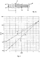
- the end face 31 lying in the control pressure chamber 4 of the control piston 21 has a diameter 47, which is larger than the diameter 48 in the Control pressure chamber 25 (26) lying face 32 of the Control piston 21. Due to this area difference points the pressure control valve 10 (10a) that shown in Figure 3 Valve identifier, which is characterized in that the course 49 of the face 32 assigned Control pressure force pA ⁇ F32 is steeper over the valve path s than the course 50 of the face 31 assigned Control pressure force pV * ⁇ F31. In this way the Supply pressure pV to a maximum value of 51 corresponding value is limited if one of the Clamp pressure control valves 7 to 9 in the open position should, so a pressure relief valve is not required becomes.
- the two embodiments differ in that Type of priority control arrangement 17 (18).
- control pressure lines 14 and 15 of the pressure control valves 7 and 8 by a 3/2-way shuttle valve 19 with a control pressure intermediate line 52 connected that this Intermediate line 52 always with the higher pressure leading control pressure line 14 or 15 communicates.
- the Control pressure intermediate line 52 and the control pressure line 16 of the pressure control valve 9 are through a 3/2-way shuttle valve 20 so with one to the control pressure chamber 25 leading control pressure output line 53 connected, that the control pressure chamber 25 always with the higher Pressure line 16 or 52, i.e. with the highest pressure leading control pressure line 14 or 15 or 16 communicates.
- control pressure line 14 of the pressure control valve 7 to the Control pressure chamber 26 of the pressure control valve 10a and Control pressure lines 15 and 16 of the pressure control valves 8 and 9 to a further control pressure chamber 27 and 29 of the Pressure control valve 10a connected.
- the Control pressure chambers 26 and 27 of the pressure control valve 10a are axial through one in the valve chamber 24a priority piston 23 slidably disposed separated from each other, which via a push rod 22 is rigidly supported relative to the control piston 21.
- the Control pressure chambers 27 and 29 are in another by the valve chamber 24a axially slidably arranged Priority control piston 28 separated from each other via the control piston 23 and the push rod 22 also is rigidly supported with respect to the control piston 21.
- control pressure line 14 If the control pressure line 14 carries the highest pressure, the control piston 23 is supported via the control piston 28 opposite the valve housing in the away from the control piston 21 pointing direction rigidly. If the Control pressure line 15 leads the highest pressure, support the control piston 23 relative to the control piston 21 and the spool 28 in the opposite direction rigidly from the valve housing. If the Control pressure line 16 carries the highest pressure, supports the control piston 28 over the control piston 23 rigidly from the control piston 21. In this way the control piston 21 is always from the control pressure of the highest working pressure pA regulating pressure control valve 7 or 8 or 9 actuated.
Description
Bei der bekannten Anordnung der DE 42 41 593 A1 zum selbsttätigen Umsteuern eines Planetenräder-Gangwechselgetriebes eines Kraftfahrzeuges aus einem bisherigen alten Gang, in welchem eine erste reibschlüssige Verbindung (Kupplung oder Bremse) durch ein zugehöriges Druckmittel-Schaltstellglied eingerückt ist, in einen neuen Gang, in welchem eine zweite reibschlüssige Verbindung durch ein zugehöriges Druckmittel-Schaltstellglied eingerückt und die erste reibschlüssige Verbindung durch Abschalten des Arbeitsdruckes des zugehörigen Schaltstellgliedes ausgerückt ist, sind Mittel zum Messen des Arbeitsdruckes des Schaltstellgliedes des neuen Ganges verwendet und der Arbeitsdruck des Schaltstellgliedes des alten Ganges abgeschaltet, wenn der Arbeitsdruck des Schaltstellgliedes des neuen Ganges einen durch einen Vergleich mit einer Bezugsgröße bestimmten signifikanten Druckwert erreicht oder übersteigt. Um das Schaltstellglied des bisherigen Ganges beim Gangwechsel auch unter Berücksichtigung von Schaltkomfort und Lebensdauer der beteiligten Schaltmittel abschalten zu können, wobei der Schaltkomfort durch den sich gegebenenfalls einstellenden Schaltruck und die Lebensdauer durch zu lange Schleifzeiten der Reibflächen beeinträchtigt sein können, ist bei dieser bekannten Anordnung vorgesehen, daß die Bezugsgröße in Abhängigkeit vom Lastdrehmoment des Antriebsmotors gegebenenfalls unter Berücksichtigung des Wandlungsverhältnisses eines hydrodynamischen Drehmomentwandlers veränderlich ist und der signifikante Druckwert zu demjenigen Momentenwert des übertragbaren Momentes der reibschlüssigen Verbindung des neuen Ganges gehört, der dem momentanen Istwert des Lastmomentes entspricht. Bei dieser bekannten Anordnung wird der Arbeitsdruck der Schaltstellglieder durch von einer elekronischen Steuereinheit ansteuerbare elektromagnetische Druckregelventile eingestellt, denen ein lastabhängiger Versorgungsdruck zugeführt wird. Über die Bildung bzw. Erzeugung dieses Versorgungsdruckes ist in der Druckschrift keine Aussage getroffen.
Die erläuterte Aufgabe ist gemäß der Erfindung mit den kennzeichnenden Merkmalen von Patentanspruch 1 in vorteilhafter Weise gelöst.
Die Schaltvorrichtung nach der Erfindung zeichnet sich dadurch aus, daß in jedem Gang nur eine reibschlüssige Verbindung eingerückt ist und mit Arbeitsdruck beaufschlagt wird. Die Arbeitsdrücke werden direkt von elektromagnetischen Vorsteuerventilen und zugeordneten Druckregelventilen geregelt. Die Arbeitsdrücke sind frei regelbar, sie weisen untereinander keine Abhängigkeiten auf. Die Schaltvorrichtung nach der Erfindung zeichnet sich ferner dadurch aus, daß den bspw. bei einem 6-Gang-Getriebe erforderlichen sechs reibschlüssigen Verbindungen bzw. deren Stellgliedern Arbeitsdruck durch Vermittlung von insgesamt nur drei Vorsteuerventilen und deren zugeordneten Druckregelventilen zugeführt wird. Die Zuordnung der geregelten Arbeitsdrücke zu den Stellgliedern kann über ein Handwählschieberventil und zwei Schaltventile erfolgen, die von einem Positionssteuerventil angesteuert werden.
Bei der Schaltvorrichtung nach der Erfindung werden die Stellglieder ausschließlich von den Druckregelventilen für den Arbeitsdruck mit Druck beaufschlagt. Ein Umschalten auf den Versorgungsdruck erfolgt nicht.
Die Schaltvorrichtung nach der Erfindung zeichnet sich desweiteren dadurch aus, daß nur der Arbeitsdruck der leistungsführenden reibschlüssigen Verbindung bzw. des zugehörigen Stellgliedes den jeweiligen notwendigen Versorgungsdruck bestimmt (Vorrang-Steuerung nach Patentanspruch 2).
- Fig. 1
- eine Schaltvorrichtung nach der Erfindung in einer ersten Ausführung, dargestellt in Form eines Blockschaltbildes mit hydraulischer Vernetzung der verwendeten Ventile,
- Fig.1a
- ein Druckregelventil der Schaltvorrichtung von Figur 1 in Einzeldarstellung,
- Fig. 2
- eine Schaltvorrichtung nach der Erfindung in einer zweiten Ausführung, dargestellt in Form eines Blockschaltbildes mit hydraulischer Vernetzung der verwendeten Ventile, und
- Fig. 3
- ein Diagramm für die Ventilkennung des Druckregelventiles für den Versorgungsdruck der Schaltvorrichtung nach der Erfindung.
Das Druckregelventil 7 regelt den Arbeitsdruck pA einer Arbeitsdruckleitung 11 - welche den Schaltstellgliedern zum Betätigen der Vorwärts-Gängen "1" und "4" zugehörigen reibschlüssigen Verbindungen über Schaltsteuerventile und ein Handwählventil zugeordnet ist - in Abhängigkeit eines lastabhängigen Steuerdruckes pA* eines elektromagnetischen Vorsteuerventiles 37, welches von einer elektronischen Steuereinheit ansteuerbar ist.
Das Druckregelventil 8 regelt den Arbeitsdruck pA einer Arbeitsdruckleitung 12 - welche dem Schaltstellglied zum Betätigen der einem Vorwärts-Gang "3" zugehörigen reibschlüssigen Verbindung über die Schaltsteuerventile und das Handwählventil zugeordnet ist - in Abhängigkeit eines lastabhängigen Steuerdruckes pA* eines elektromagnetischen Vorsteuerventiles 38, welches von der elektronischen Steuereinheit ansteuerbar ist.
Das Druckregelventil 9 regelt den Arbeitsdruck pA einer Arbeitsdruckleitung 13 - welche den Schaltstellgliedern zum Betätigen der Vorwärts-Gängen "2" und "5" und einem Rückwärts-Gang "R" zugehörigen reibschlüssigen Verbindungen über die Schaltsteuerventile und das Handwählventil zugeordnet ist - in Abhängigkeit eines lastabhängigen Steuerdruckes pA* eines elektromagnetischen Vorsteuerventiles 39, welches von der elektronischen Steuereinheit ansteuerbar ist.
Die Ventilkammer 5 ist an eine Rücklaufleitung 43 angeschlossen, welche über einen Injektor 42 mit der Saugseite der Pumpe 33 verbunden ist.
Die Ventilkammer 6 ist an die Druckleitung 35 für den Versorgungsdruck pV angeschlossen.
Die Ventilkammer 36 ist an eine zu einem Schmiersystem 45 führende Zulaufleitung 44 angeschlossen.
Die Steuerdruckkammer 40 ist durch einen Null-Anschluß 46 mit der Atmosphäre verbunden.
Im "2." Gang wirkt der Arbeitsdruck pA der Arbeitsdruckleitung 13 über den abgeleiteten Steuerdruck pA16 der Steuerdruckleitung 16 auf den Steuerkolben 28. Dessen Kolbenkraft wirkt dabei über den Steuerkolben 23 und die Druckstange 22 zusammen mit der Ventilfeder 30 am Regelkolben 21 entgegen dem von dem Versorgungsdruck pV abgeleiteten Steuerdruck pV*. Während der Schaltung wird der Arbeitsdruck pA der Arbeitsdruckleitung 13 des "2." Ganges durch das Vorsteuerventil 38 und das angeschlossene Druckregelventil 8 erhöht und der Arbeitsdruck pA der Arbeitsdruckleitung 13 des "2." Ganges durch das Vorsteuerventil 39 verringert. Sobald der Arbeitsdruck pA der Arbeitsduckleitung 12 den Arbeitsdruck pA der Arbeitsdruckleitung 13 übersteigt, trennen sich die Steuerkolben 23 und 28, so daß der Arbeitsdruck pA der Arbeitsdruckleitung 12 über den abgeleiteten Steuerdruck pA15 unter Vermittlung des Steuerkolbens 23 und der Druckstange 22 zusammmen mit der Ventilfeder 30 regelbestimmend auf den Regelkolben 21 des Druckregelventiles 10 für den Versorgungsdruck pV wirkt.
Claims (7)
- Schaltvorrichtung eines Wechselgetriebes mit einer reibschlüssigen Verbindung, durch deren Einrücken eine zugeordnete Getriebeübersetzung wirksam wird, mit einem Druckmittel-Stellglied zum Betätigen der reibschlüssigen Verbindung und einem den Arbeitsdruck (pA"1"+"4" oder pA"3" oder pA"2"+"5"+"R") des Stellgliedes in Abhängigkeit von einer elektronischen Steuereinheit einstellenden Druckregelventil (7 oder 8 oder 9), dessen Versorgungsdruck (pV) durch ein zugehöriges Druckregelventil (10 oder 10a) nach Maßgabe eines lastabhängigen Steuersignales eingestellt wird,
dadurch gekennzeichnet, daß für das lastabhängige Steuersignal ein vom Arbeitsdruck (pA) abgeleiteter Steuerdruck (pA14 oder pA15 oder pA16) verwendet ist. - Schaltvorrichtung nach Patentanspruch 1,
dadurch gekennzeichnet, daß das Druckregelventil (10,10a) für den Versorgungsdruck (pV) durch eine nach Art einer Druckwaage arbeitende Vorrang-Steuerungsanordnung (17 oder 18) mit den jeweils einen vom betreffenden Arbeitsdruck (pA) von wenigstens zwei Stellgliedern (Arbeitsdruckleitungen 11 bis 13) zum Betätigen je einer einer bestimmten Getriebeübersetzung (Gänge "1" und "4" oder "3" oder "2" und "5" und "R") zugeordneten reibschlüssigen Verbindung abgeleiteten Steuerdruck (pA14 bis pA16) führenden Steuerdruckleitungen (14 bis 16) verbunden ist. - Schaltvorrichtung nach Patentanspruch 2,
dadurch gekennzeichnet, daß für die Vorrang-Steuerungsanordnung (17) wenigstens ein 3/2-Wege-Wechselsperrventil (19 und 20) verwendet ist. - Schaltvorrichtung nach Patentanspruch 2,
dadurch gekennzeichnet, daß ein Regelkolben (21) des Druckregelventiles (10a) für den Versorgungsdruck (pV) und ein Vorrang-Steuerkolben (23) in Tandemanordnung in und relativ zu einer Ventilkammer (24a) sowie relativ zueinander axialverschiebbar angeordnet sind und eine erste Steuerdruckkammer (26) zwischen sich einschließen, daß der Vorrang-Steuerkolben (23) mit seinem dem Regelkolben (22) abgewendeten Stirnende eine zweite Steuerdruckkammer (27) in der Ventilkammer (24a) abschließt, daß beide Steuerdruckkammern (26 und 27) an je eine reibschlüssigen Verbindungen zugehörige Steuerdruckleitung (14 und 15) angeschlossen sind, und daß der Vorrang-Steuerkolben (23) gegenüber dem Regelkolben (22) in der auf den Regelkolben weisenden Richtung starr abstützbar ist. - Schaltvorrichtung nach Patentanspruch 4,
dadurch gekennzeichnet, daß die zweite Steuerdruckkammer (27) durch einen in der Ventilkammer (24a) axialverschiebbar angeordneten zweiten Vorrang-Steuerkolben (28) gegenüber einer dritten Steuerdruckkammer (29) der Ventilkammer (24a) abgeteilt ist, welche an eine reibschlüssigen Verbindungen zugehörige dritte Steuerdruckleitung (16) angeschlossen ist, und daß der zweite Vorrang-Steuerkolben (28) in der auf den Regelkolben (22) weisenden Richtung gegenüber dem ersten Vorrang-Steuerkolben (23) starr abstützbar ist. - Schaltvorrichtung nach einem der Patentansprüche 1 bis 5,
dadurch gekennzeichnet, daß das Druckregelventil (10,10a) für den Versorgungsdruck (pV) durch federnde Mittel (30) sowie durch den vom jeweiligen Arbeitsdruck (pA) abgeleiteten Steuerdruck (pA14 bis pA16) im Sinne einer Erhöhung des Versorgungsdruckes (pV) - dagegen durch einen vom Versorgungsdruck (pV) abhängigen Steuerdruck (pV*) im Sinne einer Verringerung des Versorgungsdruckes (pV) beeinflußt ist. - Schaltvorrichtung nach Patentanspruch 6,
dadurch gekennzeichnet, daß die auf den Regelkolben (21) des Druckregelventiles (10,10a) für den Versorgungsdruck (pV) wirksame Steuerdruckfläche (31) für den vom Versorgungsdruck (pV) abhängigen Steuerdruck (pV*) größer ist als die auf denselben Regelkolben wirksame Steuerdruckfläche (32) für den vom jeweiligen Arbeitsdruck (pA) abgeleiteten Steuerdruck (pA14 bis pA16).
Applications Claiming Priority (3)
| Application Number | Priority Date | Filing Date | Title |
|---|---|---|---|
| DE19735820 | 1997-08-18 | ||
| DE19735820A DE19735820B4 (de) | 1997-08-18 | 1997-08-18 | Schaltvorrichtung eines Wechselgetriebes mit Druckregelventilen für den Arbeitsdruck und einen Versorgungsdruck |
| PCT/EP1998/004870 WO1999009338A1 (de) | 1997-08-18 | 1998-08-05 | Schaltvorrichtung eines wechselgetriebes mit druckregelventilen für den arbeitsdruck und einen versorgungsdruck |
Publications (2)
| Publication Number | Publication Date |
|---|---|
| EP1003986A1 EP1003986A1 (de) | 2000-05-31 |
| EP1003986B1 true EP1003986B1 (de) | 2002-01-02 |
Family
ID=7839352
Family Applications (1)
| Application Number | Title | Priority Date | Filing Date |
|---|---|---|---|
| EP98943844A Expired - Lifetime EP1003986B1 (de) | 1997-08-18 | 1998-08-05 | Schaltvorrichtung eines wechselgetriebes mit druckregelventilen für den arbeitsdruck und einen versorgungsdruck |
Country Status (8)
| Country | Link |
|---|---|
| US (1) | US6358185B1 (de) |
| EP (1) | EP1003986B1 (de) |
| JP (1) | JP3479911B2 (de) |
| KR (1) | KR20010022867A (de) |
| CN (1) | CN1265183A (de) |
| BR (1) | BR9811211A (de) |
| DE (2) | DE19735820B4 (de) |
| WO (1) | WO1999009338A1 (de) |
Families Citing this family (6)
| Publication number | Priority date | Publication date | Assignee | Title |
|---|---|---|---|---|
| JP4158033B2 (ja) * | 2003-10-24 | 2008-10-01 | 株式会社デンソー | 自動変速機制御装置 |
| DE102005012590A1 (de) * | 2005-03-18 | 2006-09-21 | Zf Friedrichshafen Ag | Steuervorrichtung für ein Getriebe |
| US7976419B2 (en) * | 2008-12-11 | 2011-07-12 | Ford Global Technologies, Llc | Control of the flow rate in a transmission oil cooler |
| DE102010002747A1 (de) * | 2010-03-11 | 2011-09-15 | Zf Friedrichshafen Ag | Hydraulisches System zur Betätigung eines formschlüssigen Schaltelementes einer Getriebeeinrichtung |
| CN104358862B (zh) * | 2014-10-27 | 2016-05-04 | 哈尔滨东安汽车发动机制造有限公司 | 自动变速器倒档控制液压油路 |
| DE102015211599A1 (de) * | 2015-06-23 | 2016-12-29 | Zf Friedrichshafen Ag | Ventil |
Family Cites Families (22)
| Publication number | Priority date | Publication date | Assignee | Title |
|---|---|---|---|---|
| US3641845A (en) * | 1968-07-23 | 1972-02-15 | Toyota Motor Co Ltd | Oil pressure control device for fluid-type automatic transmission |
| JPS4926210B1 (de) * | 1970-01-28 | 1974-07-06 | ||
| US3885476A (en) * | 1971-07-21 | 1975-05-27 | Renault | Pressure regulation control valve for an hydraulic control system of an automatic power transmission |
| DE2537006C2 (de) * | 1975-08-20 | 1983-11-03 | Robert Bosch Gmbh, 7000 Stuttgart | Wechselgetriebe für Kraftfahrzeuge |
| DE2901051A1 (de) * | 1979-01-12 | 1980-07-24 | Bosch Gmbh Robert | Hydraulische regeleinrichtung fuer die schaltelemente von lastschaltgetrieben |
| JPS5834258A (ja) * | 1981-08-19 | 1983-02-28 | Toyota Motor Corp | 車輌用自動変速機の切換制御装置 |
| US4633737A (en) * | 1982-12-06 | 1987-01-06 | Honda Giken Kogyo Kabushiki Kaisha | Method and apparatus for minimizing pressurized fluid flow in an automatic transmission |
| US4611285A (en) * | 1984-04-05 | 1986-09-09 | Ford Motor Company | Method of controlling automatic transmission shift pressure |
| US4660442A (en) * | 1984-05-14 | 1987-04-28 | Honda Giken Kogyo K.K. | Creep-inhibiting device for an automotive vehicle equipped with an automatic transmission |
| DE3630792C2 (de) * | 1985-09-19 | 1994-10-13 | Volkswagen Ag | Druckerzeugungseinrichtung |
| JPS6383442A (ja) * | 1986-09-24 | 1988-04-14 | Aisin Seiki Co Ltd | 自動変速機の変速制御装置 |
| JP2741023B2 (ja) | 1987-04-13 | 1998-04-15 | 富士重工業株式会社 | 自動変速機の油圧制御装置 |
| JPH028551A (ja) * | 1988-06-27 | 1990-01-12 | Daikin Mfg Co Ltd | 自動車変速機の変速段切り換え制御装置 |
| DE4036076C2 (de) | 1989-11-15 | 1994-12-01 | Mazda Motor | Hydrauliksteuerung für ein Automatikgetriebe |
| DE4124385C1 (de) * | 1991-07-23 | 1993-01-07 | Mercedes-Benz Aktiengesellschaft, 7000 Stuttgart, De | |
| FR2691516B1 (fr) | 1992-05-19 | 1994-07-01 | Renault | Dispositif de controle de transmission automatique a rapports etages. |
| US5443427A (en) | 1992-06-23 | 1995-08-22 | Honda Giken Kogyo Kabushiki Kaisha | Apparatus for controlling automatic transmission |
| DE4241593C2 (de) * | 1992-12-10 | 1996-03-28 | Daimler Benz Ag | Anordnung zum selbsttätigen Umsteuern eines Planetenräder-Gangwechselgetriebes |
| JP2954707B2 (ja) * | 1995-05-06 | 1999-09-27 | ヒュンダイ モーター カンパニー | 自動車用自動変速システム |
| US5913747A (en) * | 1996-06-10 | 1999-06-22 | Hitachi, Ltd. | Hydraulic control apparatus for an automatic transmission of a vehicle |
| JP3496410B2 (ja) * | 1996-10-30 | 2004-02-09 | 日産自動車株式会社 | 自動変速機のロックアップ時ライン圧制御装置 |
| JP3026257B2 (ja) * | 1998-07-21 | 2000-03-27 | 本田技研工業株式会社 | 車両用油圧作動式変速機の制御装置 |
-
1997
- 1997-08-18 DE DE19735820A patent/DE19735820B4/de not_active Expired - Fee Related
-
1998
- 1998-08-05 JP JP2000509965A patent/JP3479911B2/ja not_active Expired - Fee Related
- 1998-08-05 US US09/486,113 patent/US6358185B1/en not_active Expired - Fee Related
- 1998-08-05 WO PCT/EP1998/004870 patent/WO1999009338A1/de active IP Right Grant
- 1998-08-05 DE DE59802806T patent/DE59802806D1/de not_active Expired - Fee Related
- 1998-08-05 CN CN98807486A patent/CN1265183A/zh active Pending
- 1998-08-05 BR BR9811211-2A patent/BR9811211A/pt not_active IP Right Cessation
- 1998-08-05 EP EP98943844A patent/EP1003986B1/de not_active Expired - Lifetime
- 1998-08-05 KR KR1020007001469A patent/KR20010022867A/ko active IP Right Grant
Also Published As
| Publication number | Publication date |
|---|---|
| JP3479911B2 (ja) | 2003-12-15 |
| US6358185B1 (en) | 2002-03-19 |
| DE19735820A1 (de) | 1999-03-04 |
| BR9811211A (pt) | 2000-07-25 |
| DE19735820B4 (de) | 2005-08-18 |
| WO1999009338A1 (de) | 1999-02-25 |
| DE59802806D1 (de) | 2002-02-28 |
| CN1265183A (zh) | 2000-08-30 |
| EP1003986A1 (de) | 2000-05-31 |
| JP2003517536A (ja) | 2003-05-27 |
| KR20010022867A (ko) | 2001-03-26 |
Similar Documents
| Publication | Publication Date | Title |
|---|---|---|
| EP0339202B1 (de) | Antriebseinrichtung für Maschinen und Fahrzeuge | |
| EP3396213B1 (de) | Verfahren zum betrieb einer getriebehydraulik mit einer hydrauliksteuerung | |
| DE3030085C2 (de) | ||
| DE60207135T2 (de) | Automatikgetriebe | |
| DE1555388B2 (de) | Hydraulische steuervorrichtung fuer den selbsttaetigen gangwechsel in einem wechselgetriebe von kraftfahrzeugen | |
| EP0728265B1 (de) | Hydrauliknotsteuerung für eine zwischen einem verbrennungsmotor und einem getriebe angeordnete reibkupplung | |
| EP0280757B1 (de) | Steuer- und Regeleinrichtung für ein stufenlos einstellbares Getriebe für Kraftfahrzeuge | |
| DE112018003351T5 (de) | Steuerungssystem und verfahren dafür für ein mehrgängiges getriebe | |
| DE102005049040A1 (de) | Hydrauliksteuergerät für ein Automatikgetriebe | |
| DE19641723A1 (de) | Stufenloses Getriebe, insbesondere mit Leistungsverzweigung | |
| EP1003986B1 (de) | Schaltvorrichtung eines wechselgetriebes mit druckregelventilen für den arbeitsdruck und einen versorgungsdruck | |
| DE2447949A1 (de) | Getriebesteuerung | |
| DE10313586A1 (de) | Automatisches Getriebe | |
| DE102020205759B3 (de) | Hydraulikkreis für ein Doppelkupplungsgetriebe sowie ein Verfahren zum Betreiben des Hydraulikkreises | |
| DE4339864A1 (de) | Stufenloses hydrostatisch-mechanisches Leistungsverzweigungsgetriebe, insbesondere für Kraftfahrzeuge | |
| DE19856544A1 (de) | Stufenloses Getriebe, insbesondere mit hydrostatischer Leistungsverzweigung mit Steuer- und Regeleinrichtung | |
| EP0444472A2 (de) | Schalteinrichtung, insbesondere für Kraftfahrzeuggetriebe | |
| DE1923809C3 (de) | Hydraulische Schaltvorrichtung für ein selbsttätig schaltbares Wechselgetriebe von Kraftfahrzeugen | |
| DE889266C (de) | Schaltung fuer mehrstufige Wechselgetriebe, insbesondere fuer Kraftfahrzeuge | |
| DE3211630C2 (de) | ||
| DE19542993A1 (de) | Stufenloses Getriebe, insbesondere mit Leistungsverzweigung | |
| DE19525823A1 (de) | Stufenloses Getriebe, insbesondere mit Leistungsverzweigung | |
| DE1275881B (de) | Steuervorrichtung zum selbsttaetigen Umschalten von Wechselgetrieben, insbesondere in Kraftfahrzeugen | |
| DE1555388C3 (de) | Hydraulische Steuervorrichtung für den selbsttätigen Gangwechsel in einem Wechselgetriebe von Kraftfahrzeugen | |
| WO2005123441A1 (de) | Steuerungseinrichtung für einen antriebsstrang eine kraftfahrzeugs |
Legal Events
| Date | Code | Title | Description |
|---|---|---|---|
| PUAI | Public reference made under article 153(3) epc to a published international application that has entered the european phase |
Free format text: ORIGINAL CODE: 0009012 |
|
| 17P | Request for examination filed |
Effective date: 19991204 |
|
| AK | Designated contracting states |
Kind code of ref document: A1 Designated state(s): DE FR GB IT |
|
| GRAG | Despatch of communication of intention to grant |
Free format text: ORIGINAL CODE: EPIDOS AGRA |
|
| GRAG | Despatch of communication of intention to grant |
Free format text: ORIGINAL CODE: EPIDOS AGRA |
|
| GRAH | Despatch of communication of intention to grant a patent |
Free format text: ORIGINAL CODE: EPIDOS IGRA |
|
| 17Q | First examination report despatched |
Effective date: 20010525 |
|
| GRAH | Despatch of communication of intention to grant a patent |
Free format text: ORIGINAL CODE: EPIDOS IGRA |
|
| GRAA | (expected) grant |
Free format text: ORIGINAL CODE: 0009210 |
|
| REG | Reference to a national code |
Ref country code: GB Ref legal event code: IF02 |
|
| AK | Designated contracting states |
Kind code of ref document: B1 Designated state(s): DE FR GB IT |
|
| PG25 | Lapsed in a contracting state [announced via postgrant information from national office to epo] |
Ref country code: IT Free format text: LAPSE BECAUSE OF FAILURE TO SUBMIT A TRANSLATION OF THE DESCRIPTION OR TO PAY THE FEE WITHIN THE PRESCRIBED TIME-LIMIT;WARNING: LAPSES OF ITALIAN PATENTS WITH EFFECTIVE DATE BEFORE 2007 MAY HAVE OCCURRED AT ANY TIME BEFORE 2007. THE CORRECT EFFECTIVE DATE MAY BE DIFFERENT FROM THE ONE RECORDED. Effective date: 20020102 Ref country code: GB Free format text: LAPSE BECAUSE OF FAILURE TO SUBMIT A TRANSLATION OF THE DESCRIPTION OR TO PAY THE FEE WITHIN THE PRESCRIBED TIME-LIMIT Effective date: 20020102 |
|
| REF | Corresponds to: |
Ref document number: 59802806 Country of ref document: DE Date of ref document: 20020228 |
|
| ET | Fr: translation filed | ||
| PLBE | No opposition filed within time limit |
Free format text: ORIGINAL CODE: 0009261 |
|
| STAA | Information on the status of an ep patent application or granted ep patent |
Free format text: STATUS: NO OPPOSITION FILED WITHIN TIME LIMIT |
|
| 26N | No opposition filed | ||
| PGFP | Annual fee paid to national office [announced via postgrant information from national office to epo] |
Ref country code: FR Payment date: 20050812 Year of fee payment: 8 |
|
| REG | Reference to a national code |
Ref country code: FR Ref legal event code: ST Effective date: 20070430 |
|
| PG25 | Lapsed in a contracting state [announced via postgrant information from national office to epo] |
Ref country code: FR Free format text: LAPSE BECAUSE OF NON-PAYMENT OF DUE FEES Effective date: 20060831 |
|
| PGFP | Annual fee paid to national office [announced via postgrant information from national office to epo] |
Ref country code: DE Payment date: 20080822 Year of fee payment: 11 |
|
| PG25 | Lapsed in a contracting state [announced via postgrant information from national office to epo] |
Ref country code: DE Free format text: LAPSE BECAUSE OF NON-PAYMENT OF DUE FEES Effective date: 20100302 |