EP1003986B1 - Dispositif de commande d'une boite de vitesses a soupapes de regulation de pression pour la pression de service et une pression d'alimentation - Google Patents
Dispositif de commande d'une boite de vitesses a soupapes de regulation de pression pour la pression de service et une pression d'alimentation Download PDFInfo
- Publication number
- EP1003986B1 EP1003986B1 EP98943844A EP98943844A EP1003986B1 EP 1003986 B1 EP1003986 B1 EP 1003986B1 EP 98943844 A EP98943844 A EP 98943844A EP 98943844 A EP98943844 A EP 98943844A EP 1003986 B1 EP1003986 B1 EP 1003986B1
- Authority
- EP
- European Patent Office
- Prior art keywords
- pressure
- control
- piston
- valve
- working
- Prior art date
- Legal status (The legal status is an assumption and is not a legal conclusion. Google has not performed a legal analysis and makes no representation as to the accuracy of the status listed.)
- Expired - Lifetime
Links
Images


Classifications
-
- F—MECHANICAL ENGINEERING; LIGHTING; HEATING; WEAPONS; BLASTING
- F16—ENGINEERING ELEMENTS AND UNITS; GENERAL MEASURES FOR PRODUCING AND MAINTAINING EFFECTIVE FUNCTIONING OF MACHINES OR INSTALLATIONS; THERMAL INSULATION IN GENERAL
- F16H—GEARING
- F16H61/00—Control functions within control units of change-speed- or reversing-gearings for conveying rotary motion ; Control of exclusively fluid gearing, friction gearing, gearings with endless flexible members or other particular types of gearing
- F16H61/0021—Generation or control of line pressure
-
- F—MECHANICAL ENGINEERING; LIGHTING; HEATING; WEAPONS; BLASTING
- F16—ENGINEERING ELEMENTS AND UNITS; GENERAL MEASURES FOR PRODUCING AND MAINTAINING EFFECTIVE FUNCTIONING OF MACHINES OR INSTALLATIONS; THERMAL INSULATION IN GENERAL
- F16H—GEARING
- F16H61/00—Control functions within control units of change-speed- or reversing-gearings for conveying rotary motion ; Control of exclusively fluid gearing, friction gearing, gearings with endless flexible members or other particular types of gearing
- F16H61/02—Control functions within control units of change-speed- or reversing-gearings for conveying rotary motion ; Control of exclusively fluid gearing, friction gearing, gearings with endless flexible members or other particular types of gearing characterised by the signals used
- F16H61/0202—Control functions within control units of change-speed- or reversing-gearings for conveying rotary motion ; Control of exclusively fluid gearing, friction gearing, gearings with endless flexible members or other particular types of gearing characterised by the signals used the signals being electric
- F16H61/0251—Elements specially adapted for electric control units, e.g. valves for converting electrical signals to fluid signals
- F16H2061/0253—Details of electro hydraulic valves, e.g. lands, ports, spools or springs
-
- F—MECHANICAL ENGINEERING; LIGHTING; HEATING; WEAPONS; BLASTING
- F16—ENGINEERING ELEMENTS AND UNITS; GENERAL MEASURES FOR PRODUCING AND MAINTAINING EFFECTIVE FUNCTIONING OF MACHINES OR INSTALLATIONS; THERMAL INSULATION IN GENERAL
- F16H—GEARING
- F16H61/00—Control functions within control units of change-speed- or reversing-gearings for conveying rotary motion ; Control of exclusively fluid gearing, friction gearing, gearings with endless flexible members or other particular types of gearing
- F16H61/04—Smoothing ratio shift
- F16H61/0437—Smoothing ratio shift by using electrical signals
Definitions
- the invention relates to a switching device Gearbox according to the preamble of claim 1.
- the pressure control valve for the supply pressure works in dependence on a load-dependent modulating pressure, for the generation of which an independent control system is required, which increases the costs of the electrohydraulic control and valuable space within the usual Way used circuit board in the gearbox claimed.
- the shifting comfort may be impaired by the shift jerk that may occur and the service life by excessively long grinding times of the friction surfaces
- the reference quantity is variable depending on the load torque of the drive motor, possibly taking into account the conversion ratio of a hydrodynamic torque converter, and the significant pressure value belongs to that torque value of the transmissible torque of the frictional connection of the new gear that corresponds to the current actual value of the load torque.
- the working pressure of the switching actuators is set by electromagnetic pressure control valves which can be controlled by an electronic control unit and to which a load-dependent supply pressure is supplied.
- the publication does not say anything about the formation or generation of this supply pressure.
- DE 36 30 792 A1 is a non-generic one Device known to generate a from the operating state of a motor vehicle dependent main pressure for actuating Switching elements of an automatic motor vehicle change gearbox provided with an adjustable feed pump is, in which the feed pump the main pressure by changing the Sets delivery rate and a control valve to deliver a a quantity adjustment device of the feed pump in the sense of Adjustment of the delivery rate Pump adjustment pressure is used.
- the problem underlying the present invention is to be seen essentially in keeping the effort for producing the load dependency of the supply pressure low in a switching device of the type mentioned at the outset.
- the stated object is achieved according to the invention with the characterizing features of claim 1 in an advantageous manner.
- the switching device according to the invention is characterized in that only one frictional connection is engaged in each gear and the working pressure is applied.
- the working pressures are controlled directly by electromagnetic pilot valves and associated pressure regulating valves.
- the working pressures are freely adjustable, they have no interdependencies.
- the switching device according to the invention is further characterized in that the six frictional connections or their actuators required for a 6-speed transmission, for example, are supplied with working pressure by arranging a total of only three pilot valves and their associated pressure control valves.
- the regulated working pressures can be assigned to the actuators via a manual slide valve and two switching valves, which are controlled by a position control valve.
- the actuators are pressurized exclusively by the pressure control valves for the working pressure. There is no switchover to the supply pressure.
- the switching device according to the invention is further characterized in that only the working pressure of the high-performance frictional connection or the associated actuator determines the respective necessary supply pressure (priority control according to claim 2).
- Valve spring of the pressure control valve concerned is the basic value of the supply pressure when the transmission is not is in a power-transmitting state (claim 6).
- Claim 3 on the one hand and claims 4,5 on the other hand each have an advantageous embodiment of the Priority control in the switching device according to the invention to the subject.
- the measure according to claim 7 is based on a Safety function of the switching device according to the invention turned off, by which it is avoided that the pressure control valve regulates an excessive pressure for the supply pressure, if a pressure control valve for the working pressure in the open position stuck.
- the supply pressure pV of the switching device is generated by a pressure pump 33 which is constantly driven by a drive motor and which sucks pressure medium from a storage container 34 and conveys it into a pressure line 35 which is connected to pressure control valves 7 to 9 for a respective working pressure pA and is connected to a pressure control valve 10 for the supply pressure pV.
- the pressure control valve 7 regulates the working pressure pA of a working pressure line 11 - which is assigned to the shift actuators for actuating the forward gears "1" and "4" associated frictional connections via shift control valves and a manual selector valve - as a function of a load-dependent control pressure pA * of an electromagnetic pilot valve 37, which can be controlled by an electronic control unit.
- the pressure control valve 8 regulates the working pressure pA of a working pressure line 12 - which is assigned to the shift actuator for actuating the frictional connection associated with a forward gear "3" via the shift control valves and the manual selector valve - as a function of a load-dependent control pressure pA * of an electromagnetic pilot valve 38, which of the electronic control unit can be controlled.
- the pressure control valve 9 regulates the working pressure pA of a working pressure line 13 - which is assigned to the shift actuators for actuating the forward gears "2" and "5" and a reverse gear “R” associated frictional connections via the shift control valves and the manual control valve - depending on one load-dependent control pressure pA * of an electromagnetic pilot valve 39, which can be controlled by the electronic control unit.
- the pressure control valves 7 to 9 are each connected to one from their working pressure line 11 or 12 or 13 branched control pressure line 14 or 15 or 16 connected, which has a priority control arrangement 17 (18 in Figure 2) with the Pressure control valve 10 (10a in Figure 2) for the supply pressure pV is connected.
- the pressure control valve 10 (10a) has a control piston 21, which has a valve chamber 24 (24a in FIG. 2) in two control pressure chambers 4 and 25 (26 in FIG. 2) lying on its end faces, in a further control pressure chamber 5 and in three valve chambers located one behind the other 5.6 and 36 divided. While the control pressure chamber 4 is connected to a control pressure line 41 branched off from the pressure line 35 via a throttle, so that the control piston 21 can be acted upon on its relevant end face with the effective pressure surface 31 by a control pressure pV * which is dependent on the supply pressure pV, a valve spring 30 acts in opposite senses on the control piston 21.
- a control pressure acts on the control piston 21, which, due to the function of the priority control arrangement 17 (18), is derived from the working pressure line 11 or 12 or 13 carrying the currently highest working pressure pA.
- the valve chamber 5 is connected to a return line 43, which is connected to the suction side of the pump 33 via an injector 42.
- the valve chamber 6 is connected to the pressure line 35 for the supply pressure pV.
- the valve chamber 36 is connected to an inlet line 44 leading to a lubrication system 45.
- the control pressure chamber 40 is connected to the atmosphere by a zero connection 46.
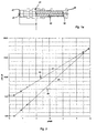
- the end face 31 lying in the control pressure chamber 4 of the control piston 21 has a diameter 47, which is larger than the diameter 48 in the Control pressure chamber 25 (26) lying face 32 of the Control piston 21. Due to this area difference points the pressure control valve 10 (10a) that shown in Figure 3 Valve identifier, which is characterized in that the course 49 of the face 32 assigned Control pressure force pA ⁇ F32 is steeper over the valve path s than the course 50 of the face 31 assigned Control pressure force pV * ⁇ F31. In this way the Supply pressure pV to a maximum value of 51 corresponding value is limited if one of the Clamp pressure control valves 7 to 9 in the open position should, so a pressure relief valve is not required becomes.
- the two embodiments differ in that Type of priority control arrangement 17 (18).
- control pressure lines 14 and 15 of the pressure control valves 7 and 8 by a 3/2-way shuttle valve 19 with a control pressure intermediate line 52 connected that this Intermediate line 52 always with the higher pressure leading control pressure line 14 or 15 communicates.
- the Control pressure intermediate line 52 and the control pressure line 16 of the pressure control valve 9 are through a 3/2-way shuttle valve 20 so with one to the control pressure chamber 25 leading control pressure output line 53 connected, that the control pressure chamber 25 always with the higher Pressure line 16 or 52, i.e. with the highest pressure leading control pressure line 14 or 15 or 16 communicates.
- control pressure line 14 of the pressure control valve 7 to the Control pressure chamber 26 of the pressure control valve 10a and Control pressure lines 15 and 16 of the pressure control valves 8 and 9 to a further control pressure chamber 27 and 29 of the Pressure control valve 10a connected.
- the Control pressure chambers 26 and 27 of the pressure control valve 10a are axial through one in the valve chamber 24a priority piston 23 slidably disposed separated from each other, which via a push rod 22 is rigidly supported relative to the control piston 21.
- the Control pressure chambers 27 and 29 are in another by the valve chamber 24a axially slidably arranged Priority control piston 28 separated from each other via the control piston 23 and the push rod 22 also is rigidly supported with respect to the control piston 21.
- control pressure line 14 If the control pressure line 14 carries the highest pressure, the control piston 23 is supported via the control piston 28 opposite the valve housing in the away from the control piston 21 pointing direction rigidly. If the Control pressure line 15 leads the highest pressure, support the control piston 23 relative to the control piston 21 and the spool 28 in the opposite direction rigidly from the valve housing. If the Control pressure line 16 carries the highest pressure, supports the control piston 28 over the control piston 23 rigidly from the control piston 21. In this way the control piston 21 is always from the control pressure of the highest working pressure pA regulating pressure control valve 7 or 8 or 9 actuated.
Landscapes
- Engineering & Computer Science (AREA)
- General Engineering & Computer Science (AREA)
- Mechanical Engineering (AREA)
- Control Of Transmission Device (AREA)
- Gear-Shifting Mechanisms (AREA)
Claims (7)
- Dispositif de commande d'une boíte de vitesses, comprenant une liaison par friction, par embrayage de laquelle un rapport de transmission est actif, un vérin de fluide de pression pour actionner la liaison par friction et une soupape de régulation de pression (8 ou 9 ou 9) réglant la pression de travail (pa"1"+"4" ou pA"3" ou pA"2"+"5"+"R") du vérin en fonction d'une unité de commande électronique, et dont la pression d'alimentation (pV) est réglée par une soupape de réglage de pression (10 ou 10a) selon un signal de commande dépendant de la charge, caractérisé en ce qu'on utilise pour le signal de commande dépendant de la charge une pression de commande (pA14 ou pA15 ou pA16) dérivée de la pression de travail (pA).
- Dispositif de commande selon la revendication 2, caractérisé en ce que la soupape de réglage de pression (10, 10a) pour la pression d'alimentation (pV) est reliée, par un agencement de commande prioritaire (17 ou 18) travaillant à la manière d'une balance de pression, avec les conduites de pression de commande (14 à 16), transportant chacune une pression de commande (pA14 à pA16) dérivée de la pression de travail concernée (pA) d'au moins deux vérins (conduites de pression de travail (11 à 13)) pour actionner chacun une liaison par friction associée à un rapport de transmission déterminé (vitesses "1" et "4" ou "3" ou "2" et "5" et "R").
- Dispositif de commande selon la revendication 2, caractérisé en ce qu'on utilise pour l'agencement de commande de priorité (17) au moins une soupape de blocage à trois voies/deux positions (19 et 20).
- Dispositif de commande selon la revendication 2, caractérisé en ce qu'un piston de régulation (21) de la soupape de régulation de pression (10a), pour la pression d'alimentation (pV) et un piston de commande prioritaire (23) sont agencés en disposition tandem dans et par rapport à une chambre de soupape (24a) ainsi qu'à déplacement axial l'un par rapport à l'autre, et enferment entre eux une première chambre de pression de commande (26), en ce que le piston de commande prioritaire (23) ferme avec son extrémité frontale détournée du piston de régulation (22) une deuxième chambre de pression de commande (27) dans la chambre de soupape (24a), en ce que les deux chambres de pression de commande (26 et 27) sont raccordées à une conduite de pression de commande (14 et 15) respective associée aux liaisons par friction, et en ce que le piston de commande prioritaire (23) peut être soutenu de manière rigide par rapport au piston de régulation (22) dans la direction tournée vers le piston de régulation.
- Dispositif de commande selon la revendication 4, caractérisé en ce que la deuxième chambre de pression de commande (27) est divisée par un deuxième piston de commande prioritaire disposé à déplacement axial dans la chambre de piston (24a) par rapport à une troisième chambre de pression de commande (29) de la chambre de soupape (24a), laquelle est raccordée à une troisième conduite de pression de commande (16) associée aux liaisons par friction, et en ce que le deuxième piston de commande prioritaire (28) peut être soutenu de manière rigide par rapport au premier piston de commande prioritaire (23) dans la direction tournée vers le piston de régulation.
- Dispositif de commande selon l'une quelconque des revendications 1 à 5, caractérisé en ce que la soupape de régulation de pression (10, 10a) pour la pression d'alimentation (pV) est influencée soit par des moyens élastiques (30) ainsi que par la pression de commande (pA14 à pA16) dérivée de la pression de travail (pA) respective dans le sens d'une augmentation de la pression d'alimentation (pV), soit au contraire par une pression de commande (pV*) dépendant de la pression d'alimentation (pV) dans le sens d'une réduction de la pression d'alimentation (pV).
- Dispositif de commande selon la revendication 6, caractérisé en ce que la surface de pression de commande (31) agissant sur le piston de régulation (21) de la soupape de régulation de pression (10, 10a) pour la pression d'alimentation (pV) est plus grande pour la pression de commande (pV*) dépendant de la pression d'alimentation (pV) que la surface de pression de commande (32) agissant sur le même piston de régulation pour la pression de commande (pA14 à pA16) dérivée de la pression de travail (pA) respective.
Applications Claiming Priority (3)
| Application Number | Priority Date | Filing Date | Title |
|---|---|---|---|
| DE19735820A DE19735820B4 (de) | 1997-08-18 | 1997-08-18 | Schaltvorrichtung eines Wechselgetriebes mit Druckregelventilen für den Arbeitsdruck und einen Versorgungsdruck |
| DE19735820 | 1997-08-18 | ||
| PCT/EP1998/004870 WO1999009338A1 (fr) | 1997-08-18 | 1998-08-05 | Dispositif de commande d'une boite de vitesses a soupapes de regulation de pression pour la pression de service et une pression d'alimentation |
Publications (2)
| Publication Number | Publication Date |
|---|---|
| EP1003986A1 EP1003986A1 (fr) | 2000-05-31 |
| EP1003986B1 true EP1003986B1 (fr) | 2002-01-02 |
Family
ID=7839352
Family Applications (1)
| Application Number | Title | Priority Date | Filing Date |
|---|---|---|---|
| EP98943844A Expired - Lifetime EP1003986B1 (fr) | 1997-08-18 | 1998-08-05 | Dispositif de commande d'une boite de vitesses a soupapes de regulation de pression pour la pression de service et une pression d'alimentation |
Country Status (8)
| Country | Link |
|---|---|
| US (1) | US6358185B1 (fr) |
| EP (1) | EP1003986B1 (fr) |
| JP (1) | JP3479911B2 (fr) |
| KR (1) | KR20010022867A (fr) |
| CN (1) | CN1265183A (fr) |
| BR (1) | BR9811211A (fr) |
| DE (2) | DE19735820B4 (fr) |
| WO (1) | WO1999009338A1 (fr) |
Families Citing this family (6)
| Publication number | Priority date | Publication date | Assignee | Title |
|---|---|---|---|---|
| JP4158033B2 (ja) * | 2003-10-24 | 2008-10-01 | 株式会社デンソー | 自動変速機制御装置 |
| DE102005012590A1 (de) * | 2005-03-18 | 2006-09-21 | Zf Friedrichshafen Ag | Steuervorrichtung für ein Getriebe |
| US7976419B2 (en) * | 2008-12-11 | 2011-07-12 | Ford Global Technologies, Llc | Control of the flow rate in a transmission oil cooler |
| DE102010002747A1 (de) * | 2010-03-11 | 2011-09-15 | Zf Friedrichshafen Ag | Hydraulisches System zur Betätigung eines formschlüssigen Schaltelementes einer Getriebeeinrichtung |
| CN104358862B (zh) * | 2014-10-27 | 2016-05-04 | 哈尔滨东安汽车发动机制造有限公司 | 自动变速器倒档控制液压油路 |
| DE102015211599A1 (de) * | 2015-06-23 | 2016-12-29 | Zf Friedrichshafen Ag | Ventil |
Family Cites Families (22)
| Publication number | Priority date | Publication date | Assignee | Title |
|---|---|---|---|---|
| US3641845A (en) * | 1968-07-23 | 1972-02-15 | Toyota Motor Co Ltd | Oil pressure control device for fluid-type automatic transmission |
| JPS4926210B1 (fr) * | 1970-01-28 | 1974-07-06 | ||
| US3885476A (en) * | 1971-07-21 | 1975-05-27 | Renault | Pressure regulation control valve for an hydraulic control system of an automatic power transmission |
| DE2537006C2 (de) * | 1975-08-20 | 1983-11-03 | Robert Bosch Gmbh, 7000 Stuttgart | Wechselgetriebe für Kraftfahrzeuge |
| DE2901051A1 (de) * | 1979-01-12 | 1980-07-24 | Bosch Gmbh Robert | Hydraulische regeleinrichtung fuer die schaltelemente von lastschaltgetrieben |
| JPS5834258A (ja) * | 1981-08-19 | 1983-02-28 | Toyota Motor Corp | 車輌用自動変速機の切換制御装置 |
| US4633737A (en) * | 1982-12-06 | 1987-01-06 | Honda Giken Kogyo Kabushiki Kaisha | Method and apparatus for minimizing pressurized fluid flow in an automatic transmission |
| US4611285A (en) * | 1984-04-05 | 1986-09-09 | Ford Motor Company | Method of controlling automatic transmission shift pressure |
| US4660442A (en) * | 1984-05-14 | 1987-04-28 | Honda Giken Kogyo K.K. | Creep-inhibiting device for an automotive vehicle equipped with an automatic transmission |
| DE3630792C2 (de) * | 1985-09-19 | 1994-10-13 | Volkswagen Ag | Druckerzeugungseinrichtung |
| JPS6383442A (ja) * | 1986-09-24 | 1988-04-14 | Aisin Seiki Co Ltd | 自動変速機の変速制御装置 |
| JP2741023B2 (ja) | 1987-04-13 | 1998-04-15 | 富士重工業株式会社 | 自動変速機の油圧制御装置 |
| JPH028551A (ja) * | 1988-06-27 | 1990-01-12 | Daikin Mfg Co Ltd | 自動車変速機の変速段切り換え制御装置 |
| DE4036076C2 (de) | 1989-11-15 | 1994-12-01 | Mazda Motor | Hydrauliksteuerung für ein Automatikgetriebe |
| DE4124385C1 (fr) * | 1991-07-23 | 1993-01-07 | Mercedes-Benz Aktiengesellschaft, 7000 Stuttgart, De | |
| FR2691516B1 (fr) | 1992-05-19 | 1994-07-01 | Renault | Dispositif de controle de transmission automatique a rapports etages. |
| US5443427A (en) | 1992-06-23 | 1995-08-22 | Honda Giken Kogyo Kabushiki Kaisha | Apparatus for controlling automatic transmission |
| DE4241593C2 (de) * | 1992-12-10 | 1996-03-28 | Daimler Benz Ag | Anordnung zum selbsttätigen Umsteuern eines Planetenräder-Gangwechselgetriebes |
| US5921888A (en) * | 1995-05-06 | 1999-07-13 | Hyundai Motor Company | Automatic transmission system for automotive vehicle |
| DE19724446A1 (de) * | 1996-06-10 | 1997-12-11 | Hitachi Ltd | Hydraulische Steuereinrichtung für ein Automatikgetriebe eines Kraftfahrzeugs |
| JP3496410B2 (ja) * | 1996-10-30 | 2004-02-09 | 日産自動車株式会社 | 自動変速機のロックアップ時ライン圧制御装置 |
| JP3026257B2 (ja) * | 1998-07-21 | 2000-03-27 | 本田技研工業株式会社 | 車両用油圧作動式変速機の制御装置 |
-
1997
- 1997-08-18 DE DE19735820A patent/DE19735820B4/de not_active Expired - Fee Related
-
1998
- 1998-08-05 CN CN98807486A patent/CN1265183A/zh active Pending
- 1998-08-05 BR BR9811211-2A patent/BR9811211A/pt not_active IP Right Cessation
- 1998-08-05 JP JP2000509965A patent/JP3479911B2/ja not_active Expired - Fee Related
- 1998-08-05 EP EP98943844A patent/EP1003986B1/fr not_active Expired - Lifetime
- 1998-08-05 DE DE59802806T patent/DE59802806D1/de not_active Expired - Fee Related
- 1998-08-05 KR KR1020007001469A patent/KR20010022867A/ko active IP Right Grant
- 1998-08-05 US US09/486,113 patent/US6358185B1/en not_active Expired - Fee Related
- 1998-08-05 WO PCT/EP1998/004870 patent/WO1999009338A1/fr active IP Right Grant
Also Published As
| Publication number | Publication date |
|---|---|
| JP2003517536A (ja) | 2003-05-27 |
| DE19735820B4 (de) | 2005-08-18 |
| DE59802806D1 (de) | 2002-02-28 |
| DE19735820A1 (de) | 1999-03-04 |
| WO1999009338A1 (fr) | 1999-02-25 |
| BR9811211A (pt) | 2000-07-25 |
| JP3479911B2 (ja) | 2003-12-15 |
| EP1003986A1 (fr) | 2000-05-31 |
| US6358185B1 (en) | 2002-03-19 |
| KR20010022867A (ko) | 2001-03-26 |
| CN1265183A (zh) | 2000-08-30 |
Similar Documents
| Publication | Publication Date | Title |
|---|---|---|
| EP0339202B1 (fr) | Dispositif de transmission pour machines et véhicules | |
| DE69126327T2 (de) | Elektrohydraulisches steuergerät für einen antriebsstrang eines fahrzeugs | |
| EP3396213B1 (fr) | Procédé de fonctionnement d'une transmission hydraulique à une commande hydraulique | |
| DE3030085C2 (fr) | ||
| DE60207135T2 (de) | Automatikgetriebe | |
| DE1555388B2 (de) | Hydraulische steuervorrichtung fuer den selbsttaetigen gangwechsel in einem wechselgetriebe von kraftfahrzeugen | |
| EP0728265B1 (fr) | Commande hydraulique de secours pour un embrayage a friction monte entre un moteur a combustion interne et une boite de vitesses | |
| EP0280757B1 (fr) | Dispositif de régulation et de commande pour une boîte de vitesses à variation continue pour véhicules à moteur | |
| DE68906116T2 (de) | Regelsystem fuer ein wahlweise zwei- oder vierradangetriebenes kraftfahrzeug mit einem stufenlos regelbaren umschlingungsgetriebe. | |
| DE112018003351T5 (de) | Steuerungssystem und verfahren dafür für ein mehrgängiges getriebe | |
| DE102005049040A1 (de) | Hydrauliksteuergerät für ein Automatikgetriebe | |
| DE19641723A1 (de) | Stufenloses Getriebe, insbesondere mit Leistungsverzweigung | |
| EP1003986B1 (fr) | Dispositif de commande d'une boite de vitesses a soupapes de regulation de pression pour la pression de service et une pression d'alimentation | |
| DE2447949A1 (de) | Getriebesteuerung | |
| DE10313586A1 (de) | Automatisches Getriebe | |
| DE4339864A1 (de) | Stufenloses hydrostatisch-mechanisches Leistungsverzweigungsgetriebe, insbesondere für Kraftfahrzeuge | |
| DE102020205759B3 (de) | Hydraulikkreis für ein Doppelkupplungsgetriebe sowie ein Verfahren zum Betreiben des Hydraulikkreises | |
| DE19856544A1 (de) | Stufenloses Getriebe, insbesondere mit hydrostatischer Leistungsverzweigung mit Steuer- und Regeleinrichtung | |
| EP0444472A2 (fr) | Dispositif de commande, particulièrement pour véhicule à moteur | |
| DE1923809C3 (de) | Hydraulische Schaltvorrichtung für ein selbsttätig schaltbares Wechselgetriebe von Kraftfahrzeugen | |
| DE889266C (de) | Schaltung fuer mehrstufige Wechselgetriebe, insbesondere fuer Kraftfahrzeuge | |
| DE3211630C2 (fr) | ||
| DE19542993A1 (de) | Stufenloses Getriebe, insbesondere mit Leistungsverzweigung | |
| DE19525823A1 (de) | Stufenloses Getriebe, insbesondere mit Leistungsverzweigung | |
| DE1275881B (de) | Steuervorrichtung zum selbsttaetigen Umschalten von Wechselgetrieben, insbesondere in Kraftfahrzeugen |
Legal Events
| Date | Code | Title | Description |
|---|---|---|---|
| PUAI | Public reference made under article 153(3) epc to a published international application that has entered the european phase |
Free format text: ORIGINAL CODE: 0009012 |
|
| 17P | Request for examination filed |
Effective date: 19991204 |
|
| AK | Designated contracting states |
Kind code of ref document: A1 Designated state(s): DE FR GB IT |
|
| GRAG | Despatch of communication of intention to grant |
Free format text: ORIGINAL CODE: EPIDOS AGRA |
|
| GRAG | Despatch of communication of intention to grant |
Free format text: ORIGINAL CODE: EPIDOS AGRA |
|
| GRAH | Despatch of communication of intention to grant a patent |
Free format text: ORIGINAL CODE: EPIDOS IGRA |
|
| 17Q | First examination report despatched |
Effective date: 20010525 |
|
| GRAH | Despatch of communication of intention to grant a patent |
Free format text: ORIGINAL CODE: EPIDOS IGRA |
|
| GRAA | (expected) grant |
Free format text: ORIGINAL CODE: 0009210 |
|
| REG | Reference to a national code |
Ref country code: GB Ref legal event code: IF02 |
|
| AK | Designated contracting states |
Kind code of ref document: B1 Designated state(s): DE FR GB IT |
|
| PG25 | Lapsed in a contracting state [announced via postgrant information from national office to epo] |
Ref country code: IT Free format text: LAPSE BECAUSE OF FAILURE TO SUBMIT A TRANSLATION OF THE DESCRIPTION OR TO PAY THE FEE WITHIN THE PRESCRIBED TIME-LIMIT;WARNING: LAPSES OF ITALIAN PATENTS WITH EFFECTIVE DATE BEFORE 2007 MAY HAVE OCCURRED AT ANY TIME BEFORE 2007. THE CORRECT EFFECTIVE DATE MAY BE DIFFERENT FROM THE ONE RECORDED. Effective date: 20020102 Ref country code: GB Free format text: LAPSE BECAUSE OF FAILURE TO SUBMIT A TRANSLATION OF THE DESCRIPTION OR TO PAY THE FEE WITHIN THE PRESCRIBED TIME-LIMIT Effective date: 20020102 |
|
| REF | Corresponds to: |
Ref document number: 59802806 Country of ref document: DE Date of ref document: 20020228 |
|
| ET | Fr: translation filed | ||
| PLBE | No opposition filed within time limit |
Free format text: ORIGINAL CODE: 0009261 |
|
| STAA | Information on the status of an ep patent application or granted ep patent |
Free format text: STATUS: NO OPPOSITION FILED WITHIN TIME LIMIT |
|
| 26N | No opposition filed | ||
| PGFP | Annual fee paid to national office [announced via postgrant information from national office to epo] |
Ref country code: FR Payment date: 20050812 Year of fee payment: 8 |
|
| REG | Reference to a national code |
Ref country code: FR Ref legal event code: ST Effective date: 20070430 |
|
| PG25 | Lapsed in a contracting state [announced via postgrant information from national office to epo] |
Ref country code: FR Free format text: LAPSE BECAUSE OF NON-PAYMENT OF DUE FEES Effective date: 20060831 |
|
| PGFP | Annual fee paid to national office [announced via postgrant information from national office to epo] |
Ref country code: DE Payment date: 20080822 Year of fee payment: 11 |
|
| PG25 | Lapsed in a contracting state [announced via postgrant information from national office to epo] |
Ref country code: DE Free format text: LAPSE BECAUSE OF NON-PAYMENT OF DUE FEES Effective date: 20100302 |