EP1000236B1 - Moteur a combustion interne - Google Patents
Moteur a combustion interne Download PDFInfo
- Publication number
- EP1000236B1 EP1000236B1 EP98926009A EP98926009A EP1000236B1 EP 1000236 B1 EP1000236 B1 EP 1000236B1 EP 98926009 A EP98926009 A EP 98926009A EP 98926009 A EP98926009 A EP 98926009A EP 1000236 B1 EP1000236 B1 EP 1000236B1
- Authority
- EP
- European Patent Office
- Prior art keywords
- cooling liquid
- cylinder
- cylinder head
- internal combustion
- combustion engine
- Prior art date
- Legal status (The legal status is an assumption and is not a legal conclusion. Google has not performed a legal analysis and makes no representation as to the accuracy of the status listed.)
- Expired - Lifetime
Links
Images


Classifications
-
- F—MECHANICAL ENGINEERING; LIGHTING; HEATING; WEAPONS; BLASTING
- F02—COMBUSTION ENGINES; HOT-GAS OR COMBUSTION-PRODUCT ENGINE PLANTS
- F02F—CYLINDERS, PISTONS OR CASINGS, FOR COMBUSTION ENGINES; ARRANGEMENTS OF SEALINGS IN COMBUSTION ENGINES
- F02F1/00—Cylinders; Cylinder heads
- F02F1/02—Cylinders; Cylinder heads having cooling means
- F02F1/10—Cylinders; Cylinder heads having cooling means for liquid cooling
- F02F1/14—Cylinders with means for directing, guiding or distributing liquid stream
-
- F—MECHANICAL ENGINEERING; LIGHTING; HEATING; WEAPONS; BLASTING
- F01—MACHINES OR ENGINES IN GENERAL; ENGINE PLANTS IN GENERAL; STEAM ENGINES
- F01P—COOLING OF MACHINES OR ENGINES IN GENERAL; COOLING OF INTERNAL-COMBUSTION ENGINES
- F01P3/00—Liquid cooling
- F01P3/02—Arrangements for cooling cylinders or cylinder heads
-
- F—MECHANICAL ENGINEERING; LIGHTING; HEATING; WEAPONS; BLASTING
- F02—COMBUSTION ENGINES; HOT-GAS OR COMBUSTION-PRODUCT ENGINE PLANTS
- F02F—CYLINDERS, PISTONS OR CASINGS, FOR COMBUSTION ENGINES; ARRANGEMENTS OF SEALINGS IN COMBUSTION ENGINES
- F02F1/00—Cylinders; Cylinder heads
- F02F1/02—Cylinders; Cylinder heads having cooling means
- F02F1/10—Cylinders; Cylinder heads having cooling means for liquid cooling
- F02F1/108—Siamese-type cylinders, i.e. cylinders cast together
-
- F—MECHANICAL ENGINEERING; LIGHTING; HEATING; WEAPONS; BLASTING
- F02—COMBUSTION ENGINES; HOT-GAS OR COMBUSTION-PRODUCT ENGINE PLANTS
- F02F—CYLINDERS, PISTONS OR CASINGS, FOR COMBUSTION ENGINES; ARRANGEMENTS OF SEALINGS IN COMBUSTION ENGINES
- F02F1/00—Cylinders; Cylinder heads
- F02F1/24—Cylinder heads
- F02F1/42—Shape or arrangement of intake or exhaust channels in cylinder heads
- F02F1/4214—Shape or arrangement of intake or exhaust channels in cylinder heads specially adapted for four or more valves per cylinder
-
- F—MECHANICAL ENGINEERING; LIGHTING; HEATING; WEAPONS; BLASTING
- F01—MACHINES OR ENGINES IN GENERAL; ENGINE PLANTS IN GENERAL; STEAM ENGINES
- F01P—COOLING OF MACHINES OR ENGINES IN GENERAL; COOLING OF INTERNAL-COMBUSTION ENGINES
- F01P3/00—Liquid cooling
- F01P3/02—Arrangements for cooling cylinders or cylinder heads
- F01P2003/021—Cooling cylinders
-
- F—MECHANICAL ENGINEERING; LIGHTING; HEATING; WEAPONS; BLASTING
- F01—MACHINES OR ENGINES IN GENERAL; ENGINE PLANTS IN GENERAL; STEAM ENGINES
- F01P—COOLING OF MACHINES OR ENGINES IN GENERAL; COOLING OF INTERNAL-COMBUSTION ENGINES
- F01P3/00—Liquid cooling
- F01P3/02—Arrangements for cooling cylinders or cylinder heads
- F01P2003/024—Cooling cylinder heads
-
- F—MECHANICAL ENGINEERING; LIGHTING; HEATING; WEAPONS; BLASTING
- F02—COMBUSTION ENGINES; HOT-GAS OR COMBUSTION-PRODUCT ENGINE PLANTS
- F02B—INTERNAL-COMBUSTION PISTON ENGINES; COMBUSTION ENGINES IN GENERAL
- F02B75/00—Other engines
- F02B75/16—Engines characterised by number of cylinders, e.g. single-cylinder engines
- F02B75/18—Multi-cylinder engines
- F02B2075/1804—Number of cylinders
- F02B2075/182—Number of cylinders five
-
- F—MECHANICAL ENGINEERING; LIGHTING; HEATING; WEAPONS; BLASTING
- F02—COMBUSTION ENGINES; HOT-GAS OR COMBUSTION-PRODUCT ENGINE PLANTS
- F02B—INTERNAL-COMBUSTION PISTON ENGINES; COMBUSTION ENGINES IN GENERAL
- F02B75/00—Other engines
- F02B75/16—Engines characterised by number of cylinders, e.g. single-cylinder engines
- F02B75/18—Multi-cylinder engines
- F02B75/20—Multi-cylinder engines with cylinders all in one line
-
- F—MECHANICAL ENGINEERING; LIGHTING; HEATING; WEAPONS; BLASTING
- F02—COMBUSTION ENGINES; HOT-GAS OR COMBUSTION-PRODUCT ENGINE PLANTS
- F02F—CYLINDERS, PISTONS OR CASINGS, FOR COMBUSTION ENGINES; ARRANGEMENTS OF SEALINGS IN COMBUSTION ENGINES
- F02F1/00—Cylinders; Cylinder heads
- F02F1/02—Cylinders; Cylinder heads having cooling means
- F02F1/10—Cylinders; Cylinder heads having cooling means for liquid cooling
- F02F2001/104—Cylinders; Cylinder heads having cooling means for liquid cooling using an open deck, i.e. the water jacket is open at the block top face
-
- F—MECHANICAL ENGINEERING; LIGHTING; HEATING; WEAPONS; BLASTING
- F02—COMBUSTION ENGINES; HOT-GAS OR COMBUSTION-PRODUCT ENGINE PLANTS
- F02F—CYLINDERS, PISTONS OR CASINGS, FOR COMBUSTION ENGINES; ARRANGEMENTS OF SEALINGS IN COMBUSTION ENGINES
- F02F1/00—Cylinders; Cylinder heads
- F02F1/02—Cylinders; Cylinder heads having cooling means
- F02F1/10—Cylinders; Cylinder heads having cooling means for liquid cooling
- F02F2001/106—Cylinders; Cylinder heads having cooling means for liquid cooling using a closed deck, i.e. the water jacket is not open at the block top face
-
- F—MECHANICAL ENGINEERING; LIGHTING; HEATING; WEAPONS; BLASTING
- F02—COMBUSTION ENGINES; HOT-GAS OR COMBUSTION-PRODUCT ENGINE PLANTS
- F02F—CYLINDERS, PISTONS OR CASINGS, FOR COMBUSTION ENGINES; ARRANGEMENTS OF SEALINGS IN COMBUSTION ENGINES
- F02F1/00—Cylinders; Cylinder heads
- F02F1/24—Cylinder heads
- F02F2001/244—Arrangement of valve stems in cylinder heads
- F02F2001/245—Arrangement of valve stems in cylinder heads the valve stems being orientated at an angle with the cylinder axis
- F02F2001/246—Arrangement of valve stems in cylinder heads the valve stems being orientated at an angle with the cylinder axis and orientated radially from the combustion chamber surface
-
- F—MECHANICAL ENGINEERING; LIGHTING; HEATING; WEAPONS; BLASTING
- F02—COMBUSTION ENGINES; HOT-GAS OR COMBUSTION-PRODUCT ENGINE PLANTS
- F02F—CYLINDERS, PISTONS OR CASINGS, FOR COMBUSTION ENGINES; ARRANGEMENTS OF SEALINGS IN COMBUSTION ENGINES
- F02F1/00—Cylinders; Cylinder heads
- F02F1/24—Cylinder heads
- F02F2001/244—Arrangement of valve stems in cylinder heads
- F02F2001/247—Arrangement of valve stems in cylinder heads the valve stems being orientated in parallel with the cylinder axis
Definitions
- the present invention relates to an internal combustion engine comprising a cylinder block with at least two cylinders and at least two exhaust valves per cylinder, a slit in the cylinder block between each pair of cylinders, and a cooling system which comprises an inlet opening for cooling liquid, formed in the cylinder block, an outlet opening for cooling liquid, formed in a cylinder head, a restriction member which is arranged in the cylinder block and guides most of the cooling water flow to an intake side of the cylinder block, and cooling liquid channels in the cylinder head which are chiefly located on an exhaust side of the cylinder head.
- One object of the present invention is to provide satisfactory cooling of the area between the exhaust valve seats in the cylinder head of an internal combustion engine.
- Another object of the present invention is to make available a locally controlled cooling of the area between the exhaust valve seats of an internal combustion engine.
- Yet another object of the present invention is to provide a satisfactory cooling liquid flow through the slits between each pair of cylinders in order thereby to create a satisfactory and uniform cooling of cylinders and cylinder liners and thereby counteract deformation of cylinder and liner.
- cooling liquid channels open into the cylinder head in an area between the exhaust valve seats for each cylinder.
- An internal combustion engine having such a cooling system creates a satisfactory and uniform cooling of the cylinders and the cylinder liners, and at the same time a satisfactory cooling of the cylinder head in the region between the exhaust valve seats is obtained, which among other things makes it easier to achieve stoichiometric combustion at high load.
- Figures 1 - 3 show a cylinder block 1 with associated cylinder head 2 and cylinder head gasket 4 for forming an internal combustion engine 6.
- the internal combustion engine 6 according to the illustrative embodiment shown is designed with five cylinders 8 in a row.
- the cylinders 8 are numbered one to five (I - V), where cylinder number one (I) is situated furthest to the left and cylinder number five (V) is situated furthest to the right in Fig. 3.
- Each cylinder 8 is provided with two inlet valves 10 and two exhaust valves 12 which cooperate with respective valve seats 14, 16 in the cylinder head 2.
- a cooling liquid channel 18a - 18e opens out between the exhaust valve seats 16 for each cylinder 8.
- the cooling liquid channels 18a - 18e create a flow communication for cooling liquid 20 between the cylinder block 1 and the cylinder head 2.
- the cooling liquid channels 18a - 18e have the same cross-sectional area relative to one another.
- a central hole 21 is also formed in each cylinder 8, which hole is intended for an ignition pin (not shown).
- a cylinder head gasket 4 Arranged between the cylinder block 1 and the cylinder head 2 there is a cylinder head gasket 4 which is provided with a number of holes 22a - 22e intended to cooperate with the cooling liquid channels 18a - 18e in the cylinder head 2.
- the holes 22a - 22e have different cross-sections for the purpose of creating a locally controlled cooling liquid flow in the respective channel 18a - 18e and thus for obtaining essentially the same volume flow through all the channels 18a - 18e. This is described in more detail below.
- a further hole 24 for cooling water is arranged in the gasket 4 of cylinder number five (V) in order to allow the cooling liquid 20 to flow round cylinder number five (V) and thereby create a uniform flow of cooling liquid around this cylinder (V).
- At cylinder number one (I) there is also a hole 26 in the gasket, which hole 26 ensures that any air bubbles in the cooling liquid 20 are led off from the cylinder block 1.
- Fig. 3 shows how slits 28 are formed in a partition wall 30 which is arranged between each adjoining cylinder 8.
- the width of the slits 28 is about 1 mm and they have a depth of about 20 mm.
- the purpose of the slits 28 is to relieve the cylinders 8, and cylinder liners 32 arranged in the cylinders 8, from stresses in the longitudinal direction of the internal combustion engine 6, which stresses derive from, among other things, heat development in the internal combustion engine 6. If the stresses become too great, the cylinders 8 and the liners 32 can become deformed and non-round, which leads among other things to increased friction between piston (not shown) and liner 32 and to increased oil consumption, which leads to increased emissions.
- the deformation of the cylinders 8 and the liners 32 also leads to gas leakage between piston and liner, so-called blow-by, and also to increased vibrations and loss of power.
- cooling liquid 20 is conveyed through the slits 28.
- Fig. 3 also shows how a restriction member 34 is arranged in the cylinder block 1 close to an inlet opening 36 for the cooling liquid 20.
- the restriction member 34 can consist, for example, of a bent plate which is preferably shaped in such a way that it causes as small as possible a drop in pressure of the cooling liquid 20.
- the restriction member 34 can also consist of a unit cast into the cylinder block 1.
- the purpose of the restriction member 34 is to guide the principal cooling liquid flow to an intake side 38 of the cylinder block 1.
- Intake side 38 here signifies that side of the cylinders 8 on which the inlet valves 10 are located, and principal flow here signifies at least 75% of the flow.
- the restriction member will preferably guide at least 90% of the cooling liquid flow to the intake side 38 of the cylinder block 1.
- Fig. 4 shows a second embodiment in which each cylinder 8 of an internal combustion engine 6 is provided with three exhaust valves 12 and two inlet valves 10. According to this embodiment, the cooling liquid channels 18a open out between respective pairs of exhaust valves 12 in the cylinder head 2.
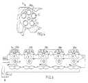
- Fig. 5 shows a diagrammatic outline of how cooling liquid 20 flows in an internal combustion engine 6 according to the invention.
- the cooling liquid 20 is led into the cylinder block 1 through the inlet opening 36 under pressure which is obtained by means of a cooling liquid pump (not shown). Most of the cooling liquid flow is thereafter guided by the restriction member 34 in the direction towards the intake side 38 of the engine 6.
- the cooling liquid channels 18a - 18e which lead the cooling liquid 20 to the cylinder head 2 are chiefly located on an exhaust side 40 of the cylinder block 1, which means that the pressure of the cooling liquid 20 is lower on the exhaust side 40 and higher on the intake side 38.
- Exhaust side 40 here signifies that side of the cylinders 8 on which the exhaust valves 12 are located. This leads to the cooling liquid 20 seeking to flow towards the exhaust side 40.
- the slits 28 extend from the intake side 38 to the exhaust side 40, the pressure difference of the cooling liquid 20 between intake side 38 and exhaust side 40 will cause cooling liquid 20 to flow in the slits 28 in the direction towards the exhaust side 40.
- the pressure on the intake side 38 drops successively in the direction towards cylinder number five (V).
- the holes 22a - 22e which are formed in the cylinder head gasket 4, and which cooperate with the cooling liquid channels 18a - 18e in the cylinder head 2, are formed with different cross-sections.
- the hole 22a nearest the inlet opening 36 for the cooling liquid 20 has the smallest cross-section.
- the hole cross-section then increases successively and is largest at cylinder number five (V) .
- a further hole 24 is arranged on cylinder number five (V), which is described above.
- V cylinder number five
- the cooling liquid channels 18a - 18e can themselves be designed with different cross-sectional areas.
- the holes 22a - 22e in the cylinder head gasket 4 can also have essentially the same cross-section and shape and the cross-section and shape of the cooling liquid channels 18a - 18e in the area of the cylinder head which adjoins the cylinder head gasket 4.
- Fig. 6 shows how cooling liquid 20 flows in the cylinder head 2.
- the cooling liquid channels 18a - 18e open out in an area between the exhaust valve seats 16 for each cylinder 8 and the cooling liquid 20 leaves the cylinder head 2 by way of an outlet opening 42.
- Fig. 7 is a diagrammatic outline in perspective showing how cooling liquid 20 flows in an internal combustion engine 6 according to the invention. After the cooling liquid 20 has passed the cooling liquid channels 18a - 18e in the cylinder head 2, which open out in the area between the exhaust valve seats 16, the cooling liquid 20 flows towards an outlet opening 42 in the cylinder head 2.
- Fig. 8 shows in detail how a hole 22c in the cylinder head gasket 4 cooperates with a cooling liquid channel 18c in the cylinder head 2.
- the hole 22c has a smaller cross-section than the cross-sectional area of the cooling liquid channel 18c, which means that a controlled volume flow of the cooling liquid 20 in the cooling liquid channel 18c is obtained.
- the full line 44 symbolizes the position of the cylinder 8
- the two circles 46 in broken lines symbolize the position of the exhaust valves 12.
- Fig. 9 shows a diagrammatic perspective view of the distribution of the cooling liquid 20 in the cylinder block 1 of an internal combustion engine 6 according to the present invention.
- the arrow P 1 shows where the cooling liquid 20 enters the inlet opening 36 to the cylinder block 1.
- the principal cooling liquid flow is guided by the restriction member 34, which leads the cooling liquid 20 round cylinder number one (I), as is shown by the arrow P 2 .
- the arrow P 3 shows that a smaller part of the cooling liquid flow passes under the restriction member 34. This is to ensure a satisfactory cooling of cylinder number one (I).
- the cooling liquid 20 which flows in the cooling liquid channels 18a - 18e is also shown in Fig. 9.
- the inlet and outlet openings 36, 42 for the cooling liquid 20 can also be placed at locations in the cylinder block 1 and cylinder head 2, respectively, other than those locations shown in the embodiment in the figures.
- a five-cylinder in-line engine is shown in the embodiment according to the figures.
- the cooling system according to the invention can be applied in any internal combustion engine of the piston type, such as a V-engine.
- the said internal combustion engine can also be of the so-called open-deck type and closed-deck type, both with so-called wet liners and dry liners, and also of the monoblock type.
Landscapes
- Engineering & Computer Science (AREA)
- Chemical & Material Sciences (AREA)
- Combustion & Propulsion (AREA)
- Mechanical Engineering (AREA)
- General Engineering & Computer Science (AREA)
- Cylinder Crankcases Of Internal Combustion Engines (AREA)
Abstract
Claims (7)
- Moteur à combustion interne comprenant un bloc cylindres (1) avec au moins deux cylindres (8) et au moins deux soupapes d'échappement (12) par cylindre (8), une fente (28) sur le bloc cylindre (1), entre chaque paire de cylindre (8), et un système de refroidissement qui comprend une ouverture d'entrée (36) pour liquide de refroidissement (20), formée dans le bloc cylindres (1), une ouverture de sortie (42) pour liquide de refroidissement (20), formée dans une culasse (2), un élément de limitation (34) qui est agencé dans le bloc cylindres (1) et guide la plupart du débit d'eau de refroidissement vers un côté d'admission (38) du bloc cylindres (1), et des canaux de liquide de refroidissement (18a à 18e) dans la culasse (2) qui sont situés principalement d'un côté échappement (40) de la culasse (2), caractérisé en ce que les canaux de liquide de refroidissement (18a à 18e) débouchent sur la culasse (2) dans une zone comprise entre les sièges de soupape d'échappement (16) pour chaque cylindre (8).
- Moteur à combustion interne selon la revendication 1, caractérisé en ce que l'ouverture d'entrée (36) pour liquide de refroidissement (20) dans le bloc cylindres (1) et l'ouverture de sortie (42) pour le liquide de refroidissement (8) dans la culasse (2) sont situées à une seule et même extrémité du moteur à combustion interne (6).
- Moteur à combustion interne selon la revendication 1, caractérisé en ce que l'ouverture d'entrée (36) pour liquide de refroidissement (20) dans le bloc cylindres (1) et l'ouverture de sortie (42) pour liquide de refroidissement (8) dans la culasse (2) sont situées à différentes extrémités du moteur à combustion interne (6).
- Moteur à combustion interne selon une ou plusieurs des revendications précédentes, caractérisé en ce que les canaux de liquide de refroidissement (18a à 18e) qui débouchent entre les sièges de soupape d'échappement (16) dans la culasse (2) présentent, l'un par rapport à l'autre, sensiblement la même surface en section transversale.
- Moteur à combustion interne selon une ou plusieurs des revendications précédentes, dans lequel un joint de culasse (4) est agencé entre le bloc cylindres (1) et la culasse (2), caractérisé en ce que le joint (4) comprend un certain nombre d'orifices (22a à 22e) destinés à coopérer avec les canaux de liquide de refroidissement (18a à 18e) dans la culasse (2) avec des surfaces en section transversale différentes.
- Moteur à combustion interne selon une ou plusieurs des revendications 1 à 3, caractérisé en ce que les canaux de liquide de refroidissement (18a à 18e) dans la culasse (2) présentent, l'un par rapport à l'autre, des surfaces en section transversale différentes.
- Moteur à combustion interne selon une ou plusieurs des revendications précédentes, caractérisé en ce que l'élément de limitation (34) est conçu d'une telle manière que plus de 75 %, de préférence plus de 90 %, du débit du liquide de refroidissement est guidé par l'élément de limitation (34) vers le côté d'admission (38) du bloc cylindres (1).
Applications Claiming Priority (3)
| Application Number | Priority Date | Filing Date | Title |
|---|---|---|---|
| SE9702055 | 1997-05-30 | ||
| SE9702055A SE509077C2 (sv) | 1997-05-30 | 1997-05-30 | Förbränningsmotor |
| PCT/SE1998/001003 WO1998054455A1 (fr) | 1997-05-30 | 1998-05-27 | Moteur a combustion interne |
Publications (2)
| Publication Number | Publication Date |
|---|---|
| EP1000236A1 EP1000236A1 (fr) | 2000-05-17 |
| EP1000236B1 true EP1000236B1 (fr) | 2003-07-23 |
Family
ID=20407176
Family Applications (1)
| Application Number | Title | Priority Date | Filing Date |
|---|---|---|---|
| EP98926009A Expired - Lifetime EP1000236B1 (fr) | 1997-05-30 | 1998-05-27 | Moteur a combustion interne |
Country Status (7)
| Country | Link |
|---|---|
| US (1) | US6202603B1 (fr) |
| EP (1) | EP1000236B1 (fr) |
| JP (1) | JP2002501586A (fr) |
| AU (1) | AU7793998A (fr) |
| DE (1) | DE69816619T2 (fr) |
| SE (1) | SE509077C2 (fr) |
| WO (1) | WO1998054455A1 (fr) |
Families Citing this family (25)
| Publication number | Priority date | Publication date | Assignee | Title |
|---|---|---|---|---|
| JP2003056343A (ja) * | 2001-08-10 | 2003-02-26 | Toyota Industries Corp | 内燃機関のシリンダヘッド冷却構造 |
| JP2003254152A (ja) * | 2002-02-28 | 2003-09-10 | Yanmar Co Ltd | エンジンの冷却装置 |
| KR100444468B1 (ko) | 2002-05-28 | 2004-08-16 | 현대자동차주식회사 | 엔진오일의 온도저감을 위한 엔진구조 |
| KR100444469B1 (ko) * | 2002-05-28 | 2004-08-16 | 현대자동차주식회사 | 엔진 냉각수의 냉각성능 강화를 위한 엔진구조 |
| US6988480B2 (en) * | 2002-09-16 | 2006-01-24 | Caterpillar Inc. | Cylinder block for an internal combustion engine having a locally thickened end wall |
| KR100656594B1 (ko) | 2002-10-24 | 2006-12-11 | 현대자동차주식회사 | 분리 냉각 시스템이 적용되는 엔진의 실린더 헤드와실린더 블럭용 워터 자켓의 구조 |
| JP4100279B2 (ja) * | 2003-07-16 | 2008-06-11 | 三菱自動車工業株式会社 | シリンダヘッド先行冷却式のエンジン |
| JP2005042654A (ja) * | 2003-07-24 | 2005-02-17 | Honda Motor Co Ltd | エンジンの冷却構造 |
| JP2007514550A (ja) * | 2003-12-18 | 2007-06-07 | テネドーラ ネマク エス.エー.デ シー.ヴイ. | 丈夫な薄壁付き鋳造品を製造するための方法および装置 |
| WO2005102560A2 (fr) * | 2004-04-20 | 2005-11-03 | Tenedora Nemak, S.A. De C.V. | Procede et appareil de moulage de blocs moteur en aluminium avec passage pour refroidissement de liquide dans des bandes de chemisage ultrafines |
| FR2887926B1 (fr) * | 2005-06-29 | 2010-08-13 | Peugeot Citroen Automobiles Sa | Chemise de cylindre pour un moteur a combustion interne et bloc cylindres equipes d'une telle chemise |
| US7845316B2 (en) * | 2007-07-06 | 2010-12-07 | Brp-Powertrain Gmbh & Co Kg | Internal combustion engine cooling system |
| DE102008051130B4 (de) * | 2008-10-10 | 2021-01-14 | Audi Ag | Kühlsystem für eine Brennkraftmaschine sowie Brennkraftmaschine |
| AT506000B1 (de) * | 2009-02-12 | 2010-12-15 | Avl List Gmbh | Brennkraftmaschine mit einem zylinderblock und einem zylinderkopf |
| EP2325453B1 (fr) * | 2009-07-30 | 2012-07-18 | Ford Global Technologies, LLC | Système de refroidissement |
| AT512280B1 (de) * | 2012-02-08 | 2013-07-15 | Avl List Gmbh | Flüssigkeitsgekühlte brennkraftmaschine |
| JP5903002B2 (ja) * | 2012-06-08 | 2016-04-13 | 富士重工業株式会社 | エンジンの冷却装置 |
| CN102705099A (zh) * | 2012-06-27 | 2012-10-03 | 无锡开普动力有限公司 | 发动机气缸盖的冷却结构 |
| JP6055322B2 (ja) * | 2013-01-28 | 2016-12-27 | 本田技研工業株式会社 | 内燃機関の冷却構造および当該冷却構造を備えた内燃機関の製造方法 |
| AT514793B1 (de) * | 2013-09-16 | 2015-06-15 | Avl List Gmbh | Kühlsystem für eine Brennkraftmaschine |
| KR101601236B1 (ko) * | 2014-11-26 | 2016-03-21 | 현대자동차주식회사 | 냉각수 제어밸브를 갖는 엔진시스템 |
| JP6812866B2 (ja) * | 2017-03-21 | 2021-01-13 | スズキ株式会社 | シリンダヘッド構造 |
| KR102474366B1 (ko) | 2017-12-18 | 2022-12-05 | 현대자동차 주식회사 | 차량용 엔진 냉각 시스템 |
| JP7087862B2 (ja) * | 2018-09-11 | 2022-06-21 | トヨタ自動車株式会社 | 内燃機関本体 |
| JP7553377B2 (ja) | 2021-02-08 | 2024-09-18 | ダイハツ工業株式会社 | 内燃機関 |
Family Cites Families (9)
| Publication number | Priority date | Publication date | Assignee | Title |
|---|---|---|---|---|
| JPS6043154A (ja) * | 1983-08-18 | 1985-03-07 | Nissan Motor Co Ltd | 内燃機関の冷却装置 |
| US4601265A (en) | 1985-06-28 | 1986-07-22 | Cummins Engine Company, Inc. | Internal combustion engine with improved coolant arrangement |
| CA1337039C (fr) | 1988-08-23 | 1995-09-19 | Tsuneo Konno | Systeme de refroidissement pour moteurs multi-cylindres |
| US5080049A (en) | 1991-05-10 | 1992-01-14 | General Motors Corporation | Two stroke engine with tiered cylinder cooling |
| US5386805A (en) * | 1991-06-06 | 1995-02-07 | Toyota Jidosha Kabushiki Kaisha | Cooling system of an internal combustion engine |
| FR2683263A1 (fr) * | 1991-10-31 | 1993-05-07 | Smh Management Services Ag | Moteur a combustion interne avec circuit de refroidissement perfectionne. |
| JPH07259555A (ja) | 1994-03-18 | 1995-10-09 | Toyota Motor Corp | 内燃機関の冷却装置 |
| DE19644409C1 (de) * | 1996-10-25 | 1998-01-29 | Daimler Benz Ag | Zylinderkopf einer Mehrzylinder-Brennkraftmaschine |
| US5937802A (en) * | 1997-10-08 | 1999-08-17 | Brunswick Corporation | Engine cooling system |
-
1997
- 1997-05-30 SE SE9702055A patent/SE509077C2/sv not_active IP Right Cessation
-
1998
- 1998-05-27 EP EP98926009A patent/EP1000236B1/fr not_active Expired - Lifetime
- 1998-05-27 US US09/424,762 patent/US6202603B1/en not_active Expired - Lifetime
- 1998-05-27 AU AU77939/98A patent/AU7793998A/en not_active Abandoned
- 1998-05-27 DE DE69816619T patent/DE69816619T2/de not_active Expired - Lifetime
- 1998-05-27 WO PCT/SE1998/001003 patent/WO1998054455A1/fr active IP Right Grant
- 1998-05-27 JP JP50059199A patent/JP2002501586A/ja active Pending
Also Published As
| Publication number | Publication date |
|---|---|
| JP2002501586A (ja) | 2002-01-15 |
| US6202603B1 (en) | 2001-03-20 |
| WO1998054455A1 (fr) | 1998-12-03 |
| SE9702055L (sv) | 1998-11-30 |
| SE509077C2 (sv) | 1998-11-30 |
| DE69816619T2 (de) | 2004-06-09 |
| EP1000236A1 (fr) | 2000-05-17 |
| AU7793998A (en) | 1998-12-30 |
| SE9702055D0 (sv) | 1997-05-30 |
| DE69816619D1 (de) | 2003-08-28 |
Similar Documents
| Publication | Publication Date | Title |
|---|---|---|
| EP1000236B1 (fr) | Moteur a combustion interne | |
| US6481392B1 (en) | Internal combustion engine | |
| EP1447533B1 (fr) | Dispositif de degasage pour un moteur à combustion interne | |
| US4590894A (en) | Coolant passage system of internal combustion engine | |
| US4699092A (en) | Fluid-cooled cylinder head | |
| EP1722090A2 (fr) | Culasse pour moteur à plusieurs cylindres | |
| US4377990A (en) | Cylinder read for water-cooled internal combustion engines manufacturable by the die-casting method | |
| CA1086166A (fr) | Systeme de refroidissement a flux controle pour moteur leger a mouvement alternatif | |
| US6962131B2 (en) | Water cooling device of vertical multi-cylinder engine | |
| EP0208461A2 (fr) | Moteur à combustion interne | |
| JP4652303B2 (ja) | 排気ガス還流装置を備える多気筒内燃機関 | |
| US7007637B2 (en) | Water jacket for cylinder head | |
| US2941521A (en) | Engine head | |
| US5875754A (en) | Internal combustion engine cylinder head arrangement | |
| US5983844A (en) | Cylinder head with cast cooling water channels as well as method and casting cores for producing same | |
| KR900006659A (ko) | 내연기관용 실린더헤드 | |
| JPH06264816A (ja) | 内燃機関のシリンダヘッド | |
| US6223709B1 (en) | Four cycle engine | |
| EP0698181B1 (fr) | Systeme d'induction pour moteur a combustion interne | |
| US4519363A (en) | Intake system for an internal combustion engine provided with several intake valves | |
| GB2203487A (en) | A fuel injection system component | |
| JP2888383B2 (ja) | 内燃機関のブリーザ室配置構造 | |
| JPH08177440A (ja) | 内燃機関の潤滑装置 | |
| EP0448525A1 (fr) | Circuit de refroidissement de culasse pour moteur à combustion interne | |
| US4520627A (en) | Turbocharged internal combustion engine |
Legal Events
| Date | Code | Title | Description |
|---|---|---|---|
| PUAI | Public reference made under article 153(3) epc to a published international application that has entered the european phase |
Free format text: ORIGINAL CODE: 0009012 |
|
| 17P | Request for examination filed |
Effective date: 19991129 |
|
| AK | Designated contracting states |
Kind code of ref document: A1 Designated state(s): BE DE FR GB IT SE |
|
| GRAH | Despatch of communication of intention to grant a patent |
Free format text: ORIGINAL CODE: EPIDOS IGRA |
|
| GRAH | Despatch of communication of intention to grant a patent |
Free format text: ORIGINAL CODE: EPIDOS IGRA |
|
| RAP1 | Party data changed (applicant data changed or rights of an application transferred) |
Owner name: VOLVO CAR CORPORATION |
|
| GRAA | (expected) grant |
Free format text: ORIGINAL CODE: 0009210 |
|
| AK | Designated contracting states |
Designated state(s): BE DE FR GB IT SE |
|
| PG25 | Lapsed in a contracting state [announced via postgrant information from national office to epo] |
Ref country code: IT Free format text: LAPSE BECAUSE OF FAILURE TO SUBMIT A TRANSLATION OF THE DESCRIPTION OR TO PAY THE FEE WITHIN THE PRESCRIBED TIME-LIMIT;WARNING: LAPSES OF ITALIAN PATENTS WITH EFFECTIVE DATE BEFORE 2007 MAY HAVE OCCURRED AT ANY TIME BEFORE 2007. THE CORRECT EFFECTIVE DATE MAY BE DIFFERENT FROM THE ONE RECORDED. Effective date: 20030723 Ref country code: FR Free format text: LAPSE BECAUSE OF FAILURE TO SUBMIT A TRANSLATION OF THE DESCRIPTION OR TO PAY THE FEE WITHIN THE PRESCRIBED TIME-LIMIT Effective date: 20030723 Ref country code: BE Free format text: LAPSE BECAUSE OF FAILURE TO SUBMIT A TRANSLATION OF THE DESCRIPTION OR TO PAY THE FEE WITHIN THE PRESCRIBED TIME-LIMIT Effective date: 20030723 |
|
| REG | Reference to a national code |
Ref country code: GB Ref legal event code: FG4D |
|
| REF | Corresponds to: |
Ref document number: 69816619 Country of ref document: DE Date of ref document: 20030828 Kind code of ref document: P |
|
| PG25 | Lapsed in a contracting state [announced via postgrant information from national office to epo] |
Ref country code: SE Free format text: LAPSE BECAUSE OF FAILURE TO SUBMIT A TRANSLATION OF THE DESCRIPTION OR TO PAY THE FEE WITHIN THE PRESCRIBED TIME-LIMIT Effective date: 20031023 |
|
| PGFP | Annual fee paid to national office [announced via postgrant information from national office to epo] |
Ref country code: FR Payment date: 20040503 Year of fee payment: 7 |
|
| PLBE | No opposition filed within time limit |
Free format text: ORIGINAL CODE: 0009261 |
|
| STAA | Information on the status of an ep patent application or granted ep patent |
Free format text: STATUS: NO OPPOSITION FILED WITHIN TIME LIMIT |
|
| 26N | No opposition filed |
Effective date: 20040426 |
|
| EN | Fr: translation not filed | ||
| PGFP | Annual fee paid to national office [announced via postgrant information from national office to epo] |
Ref country code: GB Payment date: 20110419 Year of fee payment: 14 |
|
| GBPC | Gb: european patent ceased through non-payment of renewal fee |
Effective date: 20120527 |
|
| PGFP | Annual fee paid to national office [announced via postgrant information from national office to epo] |
Ref country code: DE Payment date: 20121130 Year of fee payment: 15 |
|
| PG25 | Lapsed in a contracting state [announced via postgrant information from national office to epo] |
Ref country code: GB Free format text: LAPSE BECAUSE OF NON-PAYMENT OF DUE FEES Effective date: 20120527 |
|
| PG25 | Lapsed in a contracting state [announced via postgrant information from national office to epo] |
Ref country code: DE Free format text: LAPSE BECAUSE OF NON-PAYMENT OF DUE FEES Effective date: 20131203 |
|
| REG | Reference to a national code |
Ref country code: DE Ref legal event code: R119 Ref document number: 69816619 Country of ref document: DE Effective date: 20131203 |