EP0997685A2 - Düsenstock für einen Öldruckzerstäubungsbrenner sowie Abschlussventil für einen solchen Düsenstock - Google Patents
Düsenstock für einen Öldruckzerstäubungsbrenner sowie Abschlussventil für einen solchen Düsenstock Download PDFInfo
- Publication number
- EP0997685A2 EP0997685A2 EP00101727A EP00101727A EP0997685A2 EP 0997685 A2 EP0997685 A2 EP 0997685A2 EP 00101727 A EP00101727 A EP 00101727A EP 00101727 A EP00101727 A EP 00101727A EP 0997685 A2 EP0997685 A2 EP 0997685A2
- Authority
- EP
- European Patent Office
- Prior art keywords
- valve
- nozzle
- nozzle assembly
- heater
- oil
- Prior art date
- Legal status (The legal status is an assumption and is not a legal conclusion. Google has not performed a legal analysis and makes no representation as to the accuracy of the status listed.)
- Granted
Links
Images


Classifications
-
- F—MECHANICAL ENGINEERING; LIGHTING; HEATING; WEAPONS; BLASTING
- F23—COMBUSTION APPARATUS; COMBUSTION PROCESSES
- F23D—BURNERS
- F23D11/00—Burners using a direct spraying action of liquid droplets or vaporised liquid into the combustion space
- F23D11/36—Details, e.g. burner cooling means, noise reduction means
- F23D11/44—Preheating devices; Vaporising devices
- F23D11/441—Vaporising devices incorporated with burners
- F23D11/448—Vaporising devices incorporated with burners heated by electrical means
-
- F—MECHANICAL ENGINEERING; LIGHTING; HEATING; WEAPONS; BLASTING
- F16—ENGINEERING ELEMENTS AND UNITS; GENERAL MEASURES FOR PRODUCING AND MAINTAINING EFFECTIVE FUNCTIONING OF MACHINES OR INSTALLATIONS; THERMAL INSULATION IN GENERAL
- F16K—VALVES; TAPS; COCKS; ACTUATING-FLOATS; DEVICES FOR VENTING OR AERATING
- F16K23/00—Valves for preventing drip from nozzles
-
- F—MECHANICAL ENGINEERING; LIGHTING; HEATING; WEAPONS; BLASTING
- F23—COMBUSTION APPARATUS; COMBUSTION PROCESSES
- F23D—BURNERS
- F23D11/00—Burners using a direct spraying action of liquid droplets or vaporised liquid into the combustion space
- F23D11/36—Details, e.g. burner cooling means, noise reduction means
- F23D11/38—Nozzles; Cleaning devices therefor
-
- F—MECHANICAL ENGINEERING; LIGHTING; HEATING; WEAPONS; BLASTING
- F23—COMBUSTION APPARATUS; COMBUSTION PROCESSES
- F23D—BURNERS
- F23D11/00—Burners using a direct spraying action of liquid droplets or vaporised liquid into the combustion space
- F23D11/36—Details, e.g. burner cooling means, noise reduction means
- F23D11/44—Preheating devices; Vaporising devices
Definitions
- the present invention relates to the field of Burner technology. It concerns a nozzle assembly for an oil pressure atomizing burner, which nozzle stick on his one End of a nozzle space for receiving a pressure atomizing nozzle and at its other end a connector for connection has an oil supply line, and which nozzle assembly one arranged between the connecting part and the nozzle space Stop valve to interrupt the oil flow at not ignited burner. It continues to affect a shutoff valve for such a nozzle assembly.
- a nozzle assembly of the type mentioned at the outset is e.g. from the Document DE-A1-42 15 995 known.
- oil pressure atomizing burners such as for If oil heaters are used in houses, this is what is to be burned Oil by means of a pump with a pressure of several bar pressed through a pressure atomizing nozzle, there too fine Droplets atomized, mixed with blown air and in burned in a flame.
- the flame is turned by a suitable one Ignition mechanism ignited and then burns independently and stable as long as there is sufficient combustion air and oil Mass and under the necessary conditions (Pressure, flow velocity etc.) can be supplied.
- shut-off valve which prevents unwanted leakage largely prevented from oil from the nozzle.
- the end valve is to keep the supply line as small as possible mostly as an integrated part of the one Filter provided nozzle insert formed in the nozzle assembly can be screwed in and replaced if necessary can.
- shut-off valve a closure body (22) in the form of a ball by means of a membrane-like spring (24) sealing against pressed a valve surface (23). The valve only opens if there is oil at a sufficiently high pressure at the valve.
- From DE-C1-39 01 032 is a pressure atomizer nozzle with an integrated End valve known, in which instead of Spring a spiral spring is used. The attainable thereby longer valve travel is used to improve the dripping behavior to further improve the nozzle.
- EP-A1-0 566 855 by the applicant is a pressure atomizing nozzle known with integrated shut-off valve, in which by means of a helical compression spring over a closing piston a membrane sealingly pressed against a valve seat becomes.
- Another solution as disclosed in DE-A1-33 20 270 uses a valve plate instead of the membrane.
- Another solution, as described in DE-C2-38 00 300 uses a spring-loaded valve element, which with the interposition of an O-ring on a Sealing surface rests.
- the shut-off or shut-off valve is Integrated part of the screw-in and replaceable Nozzle insert. It is advantageous that the shutoff valve is placed very close to the actual nozzle and therefore the undesirable leakage of oil to a minimum is reduced.
- the disadvantage is that the valve part of the nozzle insert and therefore together with the nozzle insert is installed and removed.
- the European standard EN 293 which is approximately the corresponds to the older German standard DIN 4790 for the screw-in type Nozzle insert outer mass has been determined (Figure 1 of DIN EN 293), which should ensure that in the existing nozzle assembly of an oil burner pressure atomizer nozzles different manufacturers can be easily installed can.
- the task is for a nozzle block of the type mentioned Art solved in that the shut-off valve as automatic working valve is formed.
- the nozzle assembly compact, simple and easy to maintain build up, and to avoid unnecessary control effort.
- the valve can be considered thermal, e.g. working due to the heat of the oil preheater, or as purely mechanical, e.g. working due to the oil pressure Valve.
- a first preferred embodiment of the nozzle assembly according to The invention is characterized in that the shutoff valve A mechanically working valve is that the final valve by pressing the pressure on the nozzle block Oeles is actuated and that the final valve is a valve element comprises, which against the oil pressure by means of a preloaded compression spring sealingly pressed against a valve seat becomes. This makes it easy to set up and safe Use working end valves that are already have proven themselves as valves integrated into the nozzle insert.
- valve elements In addition to valve plates, O-rings and cones, the valve elements come or the like. Above all, bullets in question on one corresponding valve seat or against a corresponding Sealing surface are pressed.
- the valve element is designed as a membrane, the valve seat a central one on the sealing side of the membrane Inlet hole encloses which when the membrane is in contact is closed on the valve seat, the valve seat on the Sealing side of the membrane concentric from a first of the membrane covered ring groove is surrounded, in which the Oil flows out of the inlet bore when the membrane of the Valve seat lifts off, and if laterally next to the membrane at least one outlet bore running in the axial direction is provided, which with the first annular groove in Connection is established and the oil from the first ring groove to the exit of the final valve.
- the oil pressure acts as long as the valve is closed the smaller area of the diaphragm enclosed by the valve seat. When the valve opens, the pressure acts on the larger one first annular groove enclosed surface of the membrane. So that works on the compression spring a higher ratio of the two areas Force so that the membrane with a lower pressure in the Open position can be held. This means that a reduced pressure drop across the valve is achieved.
- the termination valve for the nozzle assembly is characterized in that the shutoff valve A mechanically working valve is that the final valve by pressing the pressure on the nozzle block Oeles is actuated and that the final valve is a valve element comprises, which against the oil pressure by means of a preloaded compression spring sealingly pressed against a valve seat becomes.
- Valve element is designed as a membrane
- the valve seat the sealing side of the membrane concentrically a central Inlet hole encloses which when the membrane is in contact is closed on the valve seat when the valve seat is open the sealing side of the membrane concentric from a first Ring groove is surrounded, in which the oil from the inlet bore flows when the diaphragm lifts off the valve seat and when laterally next to the membrane at least one in the axial direction extending outlet bore is provided, which with the first ring groove is connected and the oil from the leads first annular groove to the outlet of the shut-off valve.
- the membrane on the front of a valve screw is arranged, which has an external thread in the threaded blind hole can be screwed in if in the valve screw Spring chamber is embedded, which is closed by the membrane and in which the compression spring is housed, if there is a pressure pin between the compression spring and the diaphragm is provided, which is acted upon by the compression spring and pushes the diaphragm against the valve seat when the outlet bore runs in the valve screw, and if the outlet bore when the valve screw is screwed in with a second ring groove is connected, which is on the seal side the membrane surrounds the first annular groove concentrically and connected to it by at least one connecting groove is.
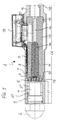
- the nozzle assembly 1 is a preferred embodiment in longitudinal section a nozzle assembly according to the invention with screwed Nozzle insert and one arranged at the outlet of the heater End valve shown.
- the nozzle assembly 1 comprises an elongated cylindrical tube 10 which at one end a nozzle space provided with an internal thread 20 for installation a pressure atomizer nozzle 2.
- the pressure atomizer nozzle 2 is in a manner known per se than in its Mass standardized screw-in nozzle insert designed and has a corresponding external thread 3rd part for this purpose of the nozzle insert is a filter 4, for example a sintered filter.
- Euronorm EN 293 protrudes the nozzle insert with a length L1 of maximum 20.5 mm in into the nozzle chamber 21, the filter 4 having a maximum Has a diameter of 11.8 mm.
- nozzle assembly 1 At the other end of the nozzle assembly 1 is in the tube 10 with a threaded part 18 fitted connector 16 fitted, to which an oil supply line (not shown) can be connected, e.g. in DE-C2-38 00 300 is described.
- Main component of the nozzle assembly 1 is arranged inside the tube 10 (Cylindrical) heater 13 for preheating the oil with one end on a diameter shoulder in the connector 16 supports.
- a compact automatic shutoff valve 5 At the other end of the heater is 13 a compact automatic shutoff valve 5 is used, the further described below in connection with FIG. 2 shall be.
- End valve 5 and heater 13 are of graduated diameters matched to each other so that they are oil-tight with each other can be connected.
- the heater 13 has an outer diameter between the two ends reduced, so that in this area between the Heater 13 and the tube 10 results in an annular gap 11, which both ends of the heater 13 by corresponding O-rings 6 and 15 against rooms 18 and 21 in the oil-filled room Nozzle block 1 is sealed.
- the heater 13 has a central through hole 14 Guide the oil to be heated, which at one end with the Threaded bore 18 in the connecting part 16 is connected, and expands towards the pressure atomizing nozzle 2 by one to record from the oil through which the heat exchanger 12 flows good heat transfer with the largest possible surface between the warm heater 13 and the oil flowing through it ensures.
- the heat exchanger 12 can e.g. as a sintered body made from a variety of metallic beads his. But there are also other heat exchangers with parallel ones Channels conceivable, such as from DE-A1-42 15 995 or DE-A1-42 16 008 are known. Heating the heater 13 takes place, for example, via a in the area of Annular gap 11 applied to the body of the heater 13 on the outside Heating winding 9.
- a temperature sensor 7 is attached to regulate the heating power.
- the leads 8 to the temperature sensor 7 and Heating winding 9 are in the annular gap 11 to a side outside on the nozzle assembly 1 attached connection box 19 with suitable Connection contacts performed, which are not discussed here shall be. It is also quite conceivable on the To waive temperature sensor 7 and instead an unregulated Use heating.
- the total length L2 of the exemplary nozzle assembly 1 from FIG. 1 is not more than about 90 mm, although in the nozzle space 21 the full installation length L1 of the Euronorm EN 293 is available stands.
- This space-saving structure is extremely extreme thanks to the compact structure of the final valve 5, which in illustrated embodiment in the axial direction Thickness of only 5.3 mm and a maximum outside diameter in Area of the circumferential shoulder (37 in Fig. 2) of 14.7 mm having.
- the inner structure of the final valve 5 is off the enlarged longitudinal sectional view in Fig. 2 can be seen.
- the closing valve 5 is in a (rotationally symmetrical to the axis) Valve housing 22 housed, which on one Side has a central inlet bore 27 for the oil, which expands conically and into the bottom of a coaxial Thread blind hole 35 opens, which of the other Side is let into the valve housing 22.
- In the bottom of the Thread blind hole 35 are also two annular grooves 26 and 25 arranged one below the other by a radial direction extending connecting groove 36 are connected and the inlet bore 27 surrounded concentrically.
- an annular valve seat 29 formed against the with the valve closed, an elastic membrane 28, the for example, consists of an oldest rubber, pressed tightly becomes.
- the preferably circular membrane 28 sits in an adapted round recess of a valve screw 23, which means an external thread 34 in the threaded blind hole 35 of the valve housing 22 can be screwed in that the membrane 28 comes to rest on the valve seat 29 and at the same time the first Ring groove 26 covered.
- a blind hole graduated in diameter introduced, which is closed by the membrane 28 and forms a spring chamber 30 in which a spiral Compression spring 32 is housed.
- the compression spring 32 presses in axial direction a mushroom-shaped pressure pin 31 against the Underside of the membrane 28, so that the membrane 28 at Normal pressure in the inlet bore 27 sealing the valve seat 29 is pressed.
- the valve seat 29 is preferably a few 1/10 mm from the bottom surface of the threaded blind hole 35 so that a secure seal when closed Valve is achieved.
- the membrane 28 automatically against the Pressure of the compression spring 32 from the valve seat 29, so that the oil from the inlet bore 27 between the valve seat 29 and the membrane 28 into the first annular groove 26, from there over the Connecting groove 36 in the second annular groove 25, and from there on the outlet bore 33 can flow to the outlet of the valve.
- the opening path of the membrane 28 or the stroke of the pressure pin 31 is only about 5/100 to 1/10 when the valve is opened mm, so that little play is provided in the spring chamber 30 got to.
- FIGS. 3 and 4 reproduced in a representation corresponding to FIGS. 1 and 2.
- FIG. 3 correspond to the tube 10 ' paragraph 17 ', heating 13', heat exchanger 12 'and the internal thread 20 'largely that with the uncoated Equivalent components from FIG. 1 designated by reference numerals, so that in Fig. 3 only the relevant section of the nozzle assembly 1 'is shown.
- Heater 13 'and heat exchanger 12' However, in contrast to FIG. 1, they form a nozzle flat end surface without a paragraph to fit the End valve 5 '.
- the nozzle space 21 ' is opposite the nozzle space 21 shortened from FIG. 1 to the length L3 of approximately 7.5 mm, what just for receiving a pressure atomizer nozzle 2 ' with the external thread 3 'but sufficient without a filter.
- the termination valve 5 ' is also equipped with a Valve housing 22 'with threaded blind hole 35' and circumferential Shoulder 37 ', a valve screw 23' with external thread 34 ', an inlet bore 27 ', an outlet bore 33', one Membrane 28 ', annular grooves 25' and 26 ', which by a connecting groove 36 'are connected, a valve seat 29', one mushroom-shaped pressure pin 31 ', and a spiral pressure spring 32 '.
- the valve housing 22 'with the inlet bore 27' is so far compared to the closing valve 5 of FIG.
- the invention results in a nozzle assembly Integrated shut-off valve, which with a small overall length Installation of standardized pressure atomizing nozzles enables, simple and is compact, easy to assemble and maintain, and does not require any additional external control effort.
Abstract
Description
- Das Magnetventil ist von seiner Bauart her fast halb so lang wie der gesamte Heizungsteil. Dies hat zur Folge, dass entweder der Düsenstock eine erheblich grössere Gesamtlänge aufweist als die üblichen Düsenstöcke, oder dass der Einbauraum für den Düseneinsatz gegenüber der Norm EN 293 wesentlich verkürzt ist, so dass normgerechte Düseneinsätze mit angebautem Filter gar nicht eingebaut werden können. Es ist dann notwendig, wie dies in der Figur der DE-A1-42 15 995 gezeigt ist, ein separates Filter am Eingang des Vorwärmers vorzusehen.
- Bedingt durch die grosse Länge des Magnetventils sind spezielle Massnahmen erforderlich, um die von der Heizung ausgehende Wärme bis zur Düse zu leiten. Dazu muss eine spezielle Hülse (48) aus gut wärmeleitendem Kupfer vorgesehen werden, die das Magnetventil thermisch überbrückt.
- Um eine wirksame Arbeitsweise des Magnetventils zu gewährleisten, muss der magnetische Kreis möglichst weitgehend geschlossen sein. Dazu wird das Aussenrohr des Düsenstocks aus einem ferromagnetischen Material gewählt, was die Materialauswahl erheblich einschränkt.
- Der Einbau der Magnetspule des Magnetventils und der elektrischen Zuführungen beansprucht nicht nur zusätzlichen Platz im Düsenstock, sondern erfordert auch einen erheblichen Montageaufwand. Dies gilt auch für ein etwaiges Auswechseln des Ventils.
- Die Ansteuerung des Magnetventils in Koordination mit dem jeweiligen Betriebszustand des Brenners erfordert einen zusätzlichen Aufwand an Mess- und Steuerelektronik und eine genaue Abstimmung der Steuerungsparameter.
- Fig. 1
- im Längsschnitt ein bevorzugtes Ausführungsbeispiel eines Düsenstockes nach der Erfindung mit eingeschraubtem Düseneinsatz und einem am Ausgang der Heizung angeordneten Abschlussventil;
- Fig. 2
- im vergrösserten Längsschnitt den Aufbau des Abschlussventils aus Fig. 1;
- Fig. 3
- im Längsschnitt einen Ausschnitt aus einem zu Fig. 1 vergleichbaren Düsenstock mit verlängertem Abschlussventil; und
- Fig. 4
- im vergrösserten Längsschnitt den Aufbau des Abschlussventils aus Fig. 3.
- 1,1'
- Düsenstock
- 2,2'
- Druckzerstäuberdüse
- 3,3'
- Aussengewinde
- 4
- Filter
- 5,5'
- Abschlussventil
- 6,6',15
- O-Ring
- 7
- Temperaturfühler
- 8
- Zuleitung
- 9
- Heizwicklung
- 10,10'
- Rohr (zylindrisch)
- 11
- Ringspalt
- 12, 12'
- Wärmetauscher
- 13,13'
- Heizung
- 14
- Durchgangsbohrung
- 16
- Anschlussteil
- 17,17'
- Absatz
- 18
- Gewindebohrung
- 19
- Anschlusskasten
- 20,20'
- Innengewinde
- 21,21'
- Düsenraum
- 22,22'
- Ventilgehäuse
- 23,23'
- Ventilschraube
- 24
- Absatz
- 25,25'
- Ringnut
- 26,26'
- Ringnut
- 27,27'
- Einlassbohrung
- 28,28'
- Membran
- 29,29'
- Ventilsitz
- 30,30'
- Federraum
- 31,31'
- Druckbolzen
- 32,32'
- Druckfeder
- 33,33'
- Auslassbohrung
- 34,34'
- Aussengewinde
- 35,35'
- Gewindesackloch
- 36,36'
- Verbindungsnut
- 37,37'
- Schulter (umlaufend)
- L1,L2,L3
- Länge
Claims (9)
- Düsenstock (1, 1') für einen Öldruckzerstäubungsbrenner, wobei der Düsenstock (1, 1') an seinem einen Ende einen Düsenraum (21,21') zur Aufnahme einer Druckzerstäuberdüse (2, 2') und an seinem anderen Ende ein Anschlußteil (16) zum Anschluß einer Ölzuführungsleitung aufweist, wobei der Düsenstock (1, 1') ein zwischen dem Anschlußteil (16) und dem Düsenraum (21) angeordnetes Abschlußventil (5, 5') zum Unterbrechen des Ölflusses bei nicht gezündetem Brenner umfaßt, und wobei das Abschlußventil (5, 5') als selbsttätig arbeitendes Ventil ausgebildetist, dadurch gekennzeichnet, daß der Düsenstock (1, 1') als Vorwärmer ausgebildet ist und eine zwischen dem Anschlußteil (16) und dem Düsenraum (21, 21') angeordnete Heizung (13, 13') zur Erwärmung des durchfließenden Öles aufweist.
- Düsenstock nach Anspruch 1, dadurch gekennzeichnet, daß das Abschlußventil (5, 5') zwischen der Heizung (13, 13') und dem Düsenraum (21, 21') angeordnet ist.
- Düsenstock nach Anspruch 1 oder 2, dadurch gekennzeichnet, daß das Abschlußventil (5, 5') als separate Baueinheit ausgebildet ist, und daß das Abschlußventil (5, 5') im Düsenstock (1, 1') direkt an die Heizung (13) anschließend angeordnet ist.
- Düsenstock nach einem oder mehreren der Ansprüche 1 bis 3, dadurch gekennzeichnet, daß die Heizung (13, 13') einen Wärmetauscher (12, 12') aufweist.
- Düsenstocknach Anspruch 4, dadurch gekennzeichnet, daß die Heizung (13) eine Durchgangsbohrung (14) zur Führung des zu wärmenden Öls aufweist, und daß der Wärmetauscher (12) in der Durchgangsbohrung (14) angeordnet ist.
- Düsenstock nach Anspruch 5, dadurch gekennzeichnet, daß sich die Durchgangsbohrung (14) zur Druckzerstäuberdüse (2) hin erweitert, um den vom Öl durchströmten Wärmetauscher (12) aufzunehmen.
- Düsenstock nach einem oder mehreren der Ansprüche 1 bis 6, dadurch gekennzeichnet, daß der Düsenstock (1) ein längliches Rohr (10) umfaßt, wobei innerhalb des Rohrs (10) die Heizung (13) angeordnet ist, und wobei innerhalb eines Ringspaltes (11) zwischen Rohr (10) und Heizung (13) eine Heizeinrichtung (9) zum Aufheizen der Heizung (13) angeordnet ist.
- Düsenstock nach Anspruch 7, dadurch gekennzeichnet, daß Zuleitungen (8) zu der Heizung (13) im Ringspalt (11) geführt sind und zu einem seitlich außen am Düsenstock (1) angebrachten Anschlußkasten (19) verlaufen.
- Düsenstock nach einem oder mehreren der Ansprüche 1 bis 8, dadurch gekennzeichnet, daß die Heizung (13) eine geregelte Heizung ist
Applications Claiming Priority (3)
| Application Number | Priority Date | Filing Date | Title |
|---|---|---|---|
| CH40596 | 1996-02-16 | ||
| CH40596 | 1996-02-16 | ||
| EP97810048A EP0790462B1 (de) | 1996-02-16 | 1997-01-31 | Düsenstock für einen Öldruckzerstäubungsbrenner sowie Abschlussventil für einen solchen Düsenstock |
Related Parent Applications (1)
| Application Number | Title | Priority Date | Filing Date |
|---|---|---|---|
| EP97810048A Division EP0790462B1 (de) | 1996-02-16 | 1997-01-31 | Düsenstock für einen Öldruckzerstäubungsbrenner sowie Abschlussventil für einen solchen Düsenstock |
Publications (3)
| Publication Number | Publication Date |
|---|---|
| EP0997685A2 true EP0997685A2 (de) | 2000-05-03 |
| EP0997685A3 EP0997685A3 (de) | 2000-07-12 |
| EP0997685B1 EP0997685B1 (de) | 2004-06-09 |
Family
ID=4186288
Family Applications (2)
| Application Number | Title | Priority Date | Filing Date |
|---|---|---|---|
| EP97810048A Expired - Lifetime EP0790462B1 (de) | 1996-02-16 | 1997-01-31 | Düsenstock für einen Öldruckzerstäubungsbrenner sowie Abschlussventil für einen solchen Düsenstock |
| EP00101727A Expired - Lifetime EP0997685B1 (de) | 1996-02-16 | 1997-01-31 | Düsenstock für einen Öldruckzerstäubungsbrenner sowie Abschlussventil für einen solchen Düsenstock |
Family Applications Before (1)
| Application Number | Title | Priority Date | Filing Date |
|---|---|---|---|
| EP97810048A Expired - Lifetime EP0790462B1 (de) | 1996-02-16 | 1997-01-31 | Düsenstock für einen Öldruckzerstäubungsbrenner sowie Abschlussventil für einen solchen Düsenstock |
Country Status (6)
| Country | Link |
|---|---|
| EP (2) | EP0790462B1 (de) |
| AT (2) | ATE201500T1 (de) |
| DE (2) | DE59703576D1 (de) |
| DK (2) | DK0997685T3 (de) |
| ES (2) | ES2222858T3 (de) |
| HU (1) | HU221282B1 (de) |
Families Citing this family (2)
| Publication number | Priority date | Publication date | Assignee | Title |
|---|---|---|---|---|
| WO2007096788A1 (de) * | 2006-02-22 | 2007-08-30 | Tempratec Ltd. | Vorrichtung und verfahren zum verbrennen eines brennstoffes |
| ATE446478T1 (de) * | 2006-02-22 | 2009-11-15 | Tempratec Ltd | Vorrichtung und verfahren zum verbrennen eines brennstoffes |
Citations (7)
| Publication number | Priority date | Publication date | Assignee | Title |
|---|---|---|---|---|
| DE3142074A1 (de) * | 1981-06-24 | 1983-01-13 | VEB Ölfeuerungsbau Karl-Marx-Stadt, DDR 9030 Karl-Marx-Stadt | Druckeinstellbarer, beheizter duesenstock fuer hochviskose heizoele |
| DE3226023A1 (de) * | 1982-07-12 | 1984-01-12 | Thermostar Heisler + Leins oHG Heizungs- und Klimatechnik, 7250 Leonberg | Duesenstock mit druckabbauvorrichtung |
| EP0215323A2 (de) * | 1985-09-12 | 1987-03-25 | Satronic Ag | Verfahren zur Regelung der Aufheiztemperatur eines Durchlauferhitzers sowie regelbare Durchlauferhitzer |
| DE3901032C1 (de) * | 1989-01-14 | 1990-02-08 | Danfoss A/S, Nordborg, Dk | |
| EP0495402A2 (de) * | 1991-01-16 | 1992-07-22 | A. Schwarz + Co. | Ölvorwärmeeinrichtung für einen Druckzerstäuberbrenner |
| DE4215995A1 (de) * | 1992-05-12 | 1993-11-18 | Rausch & Pausch | Düsenstock für Öldruckzerstäubungsbrenner |
| DE4216008A1 (de) * | 1992-05-12 | 1993-11-18 | Rausch & Pausch | Vorwärmer für Ölbrenner |
Family Cites Families (6)
| Publication number | Priority date | Publication date | Assignee | Title |
|---|---|---|---|---|
| CH428605A (de) * | 1965-08-09 | 1967-01-15 | A Sutter Fa | Ventil für Spray-Düse |
| DE3308153A1 (de) | 1983-03-08 | 1984-09-13 | Satronic AG, Regensdorf | Druckzerstaeuberduese fuer heizungsanlagen |
| DE3320270A1 (de) | 1983-06-04 | 1985-03-07 | Hubert 7000 Stuttgart Gröner | Drallduese mit integriertem absperrventil |
| US4660598A (en) * | 1986-01-13 | 1987-04-28 | Spraying Systems Co. | Diaphragm-type antidrip valve |
| DE3800300C3 (de) | 1988-01-08 | 1998-04-30 | Schaefer Stettiner Schrauben | Ölzuführeinrichtung für einen Ölzerstäubungsbrenner |
| EP0566855A1 (de) | 1992-04-24 | 1993-10-27 | Satronic Ag | Druckluft-Oelzerstäuberdüse |
-
1997
- 1997-01-31 DK DK00101727T patent/DK0997685T3/da active
- 1997-01-31 DE DE59703576T patent/DE59703576D1/de not_active Expired - Fee Related
- 1997-01-31 EP EP97810048A patent/EP0790462B1/de not_active Expired - Lifetime
- 1997-01-31 DK DK97810048T patent/DK0790462T3/da active
- 1997-01-31 ES ES00101727T patent/ES2222858T3/es not_active Expired - Lifetime
- 1997-01-31 ES ES97810048T patent/ES2159827T3/es not_active Expired - Lifetime
- 1997-01-31 EP EP00101727A patent/EP0997685B1/de not_active Expired - Lifetime
- 1997-01-31 AT AT97810048T patent/ATE201500T1/de not_active IP Right Cessation
- 1997-01-31 DE DE59711715T patent/DE59711715D1/de not_active Expired - Fee Related
- 1997-01-31 AT AT00101727T patent/ATE268883T1/de not_active IP Right Cessation
- 1997-02-14 HU HU9700448A patent/HU221282B1/hu unknown
Patent Citations (7)
| Publication number | Priority date | Publication date | Assignee | Title |
|---|---|---|---|---|
| DE3142074A1 (de) * | 1981-06-24 | 1983-01-13 | VEB Ölfeuerungsbau Karl-Marx-Stadt, DDR 9030 Karl-Marx-Stadt | Druckeinstellbarer, beheizter duesenstock fuer hochviskose heizoele |
| DE3226023A1 (de) * | 1982-07-12 | 1984-01-12 | Thermostar Heisler + Leins oHG Heizungs- und Klimatechnik, 7250 Leonberg | Duesenstock mit druckabbauvorrichtung |
| EP0215323A2 (de) * | 1985-09-12 | 1987-03-25 | Satronic Ag | Verfahren zur Regelung der Aufheiztemperatur eines Durchlauferhitzers sowie regelbare Durchlauferhitzer |
| DE3901032C1 (de) * | 1989-01-14 | 1990-02-08 | Danfoss A/S, Nordborg, Dk | |
| EP0495402A2 (de) * | 1991-01-16 | 1992-07-22 | A. Schwarz + Co. | Ölvorwärmeeinrichtung für einen Druckzerstäuberbrenner |
| DE4215995A1 (de) * | 1992-05-12 | 1993-11-18 | Rausch & Pausch | Düsenstock für Öldruckzerstäubungsbrenner |
| DE4216008A1 (de) * | 1992-05-12 | 1993-11-18 | Rausch & Pausch | Vorwärmer für Ölbrenner |
Also Published As
| Publication number | Publication date |
|---|---|
| ES2222858T3 (es) | 2005-02-16 |
| ATE268883T1 (de) | 2004-06-15 |
| EP0790462A1 (de) | 1997-08-20 |
| DE59703576D1 (de) | 2001-06-28 |
| HU9700448D0 (en) | 1997-04-28 |
| EP0997685A3 (de) | 2000-07-12 |
| DK0997685T3 (da) | 2004-07-26 |
| EP0790462B1 (de) | 2001-05-23 |
| HUP9700448A2 (en) | 1997-11-28 |
| ES2159827T3 (es) | 2001-10-16 |
| ATE201500T1 (de) | 2001-06-15 |
| EP0997685B1 (de) | 2004-06-09 |
| HUP9700448A3 (en) | 1998-01-28 |
| DE59711715D1 (de) | 2004-07-15 |
| HU221282B1 (en) | 2002-09-28 |
| DK0790462T3 (da) | 2001-08-13 |
Similar Documents
| Publication | Publication Date | Title |
|---|---|---|
| CH655984A5 (de) | Magnetventil mit leistungsverstaerker. | |
| DE2526200B2 (de) | Elektromagnetische Pumpe | |
| DE3048174A1 (de) | Magnetbetaetigte pumpe | |
| EP0593724B1 (de) | Düsenstock für öldruckzerstäubungsbrenner | |
| DE3801410A1 (de) | Kraftstoffaufbereitungsvorrichtung | |
| EP0731315B1 (de) | Düsenabschlussventil sowie Druckzerstäuberdüse mit einem solchen Düsenabschlussventil | |
| EP0997685B1 (de) | Düsenstock für einen Öldruckzerstäubungsbrenner sowie Abschlussventil für einen solchen Düsenstock | |
| DE3019167C2 (de) | ||
| DE3619840C2 (de) | Gashahn | |
| EP0943740B1 (de) | Sanitäres Mischventil | |
| DE10135115B4 (de) | Gasarmatur | |
| EP0806246A1 (de) | Düsenabschlussventil sowie Druckzerstäuberdüse mit einem solchen Düsenabschlussventil | |
| EP1353126B1 (de) | Hydraulisch geregelte Gasarmatur | |
| AT412232B (de) | Hydraulisch geregelte gasarmatur | |
| DE2049033C (de) | Thermostatisch gesteuertes Sicherheitsventil | |
| DE3434840A1 (de) | Oelbrenner fuer heizungsanlagen | |
| DE3641317C2 (de) | ||
| EP0591660A1 (de) | Hochdruckreinigungsgerät | |
| WO1997032148A1 (de) | Sicherheitsventil für eine rohrleitung | |
| DE2953785A1 (de) | Vorrichtung zur steuerung der gaszufuhr | |
| CH344978A (de) | Regelvorrichtung für Brenner | |
| DE1275015B (de) | Elektromagnetisch betaetigtes Gasventil fuer Gasbrenner | |
| CH664807A5 (en) | Gas supply twin valve for furnace - has hydraulic pump connected both directly and via pressure regulator to respective valves | |
| EP0361076A1 (de) | Temperaturgesteuertes Ventil | |
| DE4112868A1 (de) | Verdraengerpumpe |
Legal Events
| Date | Code | Title | Description |
|---|---|---|---|
| PUAI | Public reference made under article 153(3) epc to a published international application that has entered the european phase |
Free format text: ORIGINAL CODE: 0009012 |
|
| 17P | Request for examination filed |
Effective date: 20000203 |
|
| AC | Divisional application: reference to earlier application |
Ref document number: 790462 Country of ref document: EP |
|
| AK | Designated contracting states |
Kind code of ref document: A2 Designated state(s): AT BE CH DE DK ES FI FR GR IT LI NL PT SE |
|
| AX | Request for extension of the european patent |
Free format text: AL;LT;LV;RO;SI |
|
| PUAL | Search report despatched |
Free format text: ORIGINAL CODE: 0009013 |
|
| AK | Designated contracting states |
Kind code of ref document: A3 Designated state(s): AT BE CH DE DK ES FI FR GR IT LI NL PT SE |
|
| AX | Request for extension of the european patent |
Free format text: AL;LT;LV;RO;SI |
|
| AKX | Designation fees paid |
Free format text: AT BE CH DE DK ES FI FR GR IT LI NL PT SE |
|
| 17Q | First examination report despatched |
Effective date: 20010305 |
|
| GRAP | Despatch of communication of intention to grant a patent |
Free format text: ORIGINAL CODE: EPIDOSNIGR1 |
|
| GRAS | Grant fee paid |
Free format text: ORIGINAL CODE: EPIDOSNIGR3 |
|
| GRAA | (expected) grant |
Free format text: ORIGINAL CODE: 0009210 |
|
| AC | Divisional application: reference to earlier application |
Ref document number: 0790462 Country of ref document: EP Kind code of ref document: P |
|
| AK | Designated contracting states |
Kind code of ref document: B1 Designated state(s): AT BE CH DE DK ES FI FR GR IT LI NL PT SE |
|
| PG25 | Lapsed in a contracting state [announced via postgrant information from national office to epo] |
Ref country code: NL Free format text: LAPSE BECAUSE OF FAILURE TO SUBMIT A TRANSLATION OF THE DESCRIPTION OR TO PAY THE FEE WITHIN THE PRESCRIBED TIME-LIMIT Effective date: 20040609 Ref country code: FI Free format text: LAPSE BECAUSE OF FAILURE TO SUBMIT A TRANSLATION OF THE DESCRIPTION OR TO PAY THE FEE WITHIN THE PRESCRIBED TIME-LIMIT Effective date: 20040609 |
|
| REG | Reference to a national code |
Ref country code: CH Ref legal event code: NV Representative=s name: ISLER & PEDRAZZINI AG Ref country code: CH Ref legal event code: EP |
|
| REF | Corresponds to: |
Ref document number: 59711715 Country of ref document: DE Date of ref document: 20040715 Kind code of ref document: P |
|
| REG | Reference to a national code |
Ref country code: DK Ref legal event code: T3 |
|
| REG | Reference to a national code |
Ref country code: SE Ref legal event code: TRGR |
|
| REG | Reference to a national code |
Ref country code: GR Ref legal event code: EP Ref document number: 20040402994 Country of ref document: GR |
|
| NLV1 | Nl: lapsed or annulled due to failure to fulfill the requirements of art. 29p and 29m of the patents act | ||
| ET | Fr: translation filed | ||
| PG25 | Lapsed in a contracting state [announced via postgrant information from national office to epo] |
Ref country code: BE Free format text: LAPSE BECAUSE OF NON-PAYMENT OF DUE FEES Effective date: 20050131 |
|
| REG | Reference to a national code |
Ref country code: ES Ref legal event code: FG2A Ref document number: 2222858 Country of ref document: ES Kind code of ref document: T3 |
|
| PLBE | No opposition filed within time limit |
Free format text: ORIGINAL CODE: 0009261 |
|
| STAA | Information on the status of an ep patent application or granted ep patent |
Free format text: STATUS: NO OPPOSITION FILED WITHIN TIME LIMIT |
|
| 26N | No opposition filed |
Effective date: 20050310 |
|
| BERE | Be: lapsed |
Owner name: *SATRONIC A.G. Effective date: 20050131 |
|
| PGFP | Annual fee paid to national office [announced via postgrant information from national office to epo] |
Ref country code: AT Payment date: 20051212 Year of fee payment: 10 Ref country code: DK Payment date: 20051212 Year of fee payment: 10 |
|
| PGFP | Annual fee paid to national office [announced via postgrant information from national office to epo] |
Ref country code: GR Payment date: 20051229 Year of fee payment: 10 |
|
| PGFP | Annual fee paid to national office [announced via postgrant information from national office to epo] |
Ref country code: FR Payment date: 20060104 Year of fee payment: 10 |
|
| PGFP | Annual fee paid to national office [announced via postgrant information from national office to epo] |
Ref country code: SE Payment date: 20060109 Year of fee payment: 10 |
|
| PGFP | Annual fee paid to national office [announced via postgrant information from national office to epo] |
Ref country code: ES Payment date: 20060123 Year of fee payment: 10 |
|
| PGFP | Annual fee paid to national office [announced via postgrant information from national office to epo] |
Ref country code: IT Payment date: 20060131 Year of fee payment: 10 Ref country code: DE Payment date: 20060131 Year of fee payment: 10 |
|
| PGFP | Annual fee paid to national office [announced via postgrant information from national office to epo] |
Ref country code: CH Payment date: 20060308 Year of fee payment: 10 |
|
| PG25 | Lapsed in a contracting state [announced via postgrant information from national office to epo] |
Ref country code: LI Free format text: LAPSE BECAUSE OF NON-PAYMENT OF DUE FEES Effective date: 20070131 Ref country code: CH Free format text: LAPSE BECAUSE OF NON-PAYMENT OF DUE FEES Effective date: 20070131 |
|
| PG25 | Lapsed in a contracting state [announced via postgrant information from national office to epo] |
Ref country code: SE Free format text: LAPSE BECAUSE OF NON-PAYMENT OF DUE FEES Effective date: 20070201 |
|
| PG25 | Lapsed in a contracting state [announced via postgrant information from national office to epo] |
Ref country code: DE Free format text: LAPSE BECAUSE OF NON-PAYMENT OF DUE FEES Effective date: 20070801 |
|
| REG | Reference to a national code |
Ref country code: CH Ref legal event code: PL |
|
| REG | Reference to a national code |
Ref country code: DK Ref legal event code: EBP |
|
| EUG | Se: european patent has lapsed | ||
| REG | Reference to a national code |
Ref country code: FR Ref legal event code: ST Effective date: 20070930 |
|
| PG25 | Lapsed in a contracting state [announced via postgrant information from national office to epo] |
Ref country code: AT Free format text: LAPSE BECAUSE OF NON-PAYMENT OF DUE FEES Effective date: 20070131 |
|
| BERE | Be: lapsed |
Owner name: *SATRONIC A.G. Effective date: 20050131 |
|
| PG25 | Lapsed in a contracting state [announced via postgrant information from national office to epo] |
Ref country code: PT Free format text: LAPSE BECAUSE OF NON-PAYMENT OF DUE FEES Effective date: 20041109 |
|
| PG25 | Lapsed in a contracting state [announced via postgrant information from national office to epo] |
Ref country code: DK Free format text: LAPSE BECAUSE OF NON-PAYMENT OF DUE FEES Effective date: 20070131 |
|
| REG | Reference to a national code |
Ref country code: FR Ref legal event code: TP |
|
| REG | Reference to a national code |
Ref country code: ES Ref legal event code: FD2A Effective date: 20070201 |
|
| PG25 | Lapsed in a contracting state [announced via postgrant information from national office to epo] |
Ref country code: FR Free format text: LAPSE BECAUSE OF NON-PAYMENT OF DUE FEES Effective date: 20070131 |
|
| PG25 | Lapsed in a contracting state [announced via postgrant information from national office to epo] |
Ref country code: ES Free format text: LAPSE BECAUSE OF NON-PAYMENT OF DUE FEES Effective date: 20070201 |
|
| PG25 | Lapsed in a contracting state [announced via postgrant information from national office to epo] |
Ref country code: GR Free format text: LAPSE BECAUSE OF NON-PAYMENT OF DUE FEES Effective date: 20070802 |
|
| PG25 | Lapsed in a contracting state [announced via postgrant information from national office to epo] |
Ref country code: IT Free format text: LAPSE BECAUSE OF NON-PAYMENT OF DUE FEES Effective date: 20070131 |