EP0997294A2 - Tintenbehälter, Kassette damit versehen, und mit solcher Kassette ausgerüstetes Druckwerk - Google Patents
Tintenbehälter, Kassette damit versehen, und mit solcher Kassette ausgerüstetes Druckwerk Download PDFInfo
- Publication number
- EP0997294A2 EP0997294A2 EP99121297A EP99121297A EP0997294A2 EP 0997294 A2 EP0997294 A2 EP 0997294A2 EP 99121297 A EP99121297 A EP 99121297A EP 99121297 A EP99121297 A EP 99121297A EP 0997294 A2 EP0997294 A2 EP 0997294A2
- Authority
- EP
- European Patent Office
- Prior art keywords
- ink
- ink tank
- prism
- light
- surface energy
- Prior art date
- Legal status (The legal status is an assumption and is not a legal conclusion. Google has not performed a legal analysis and makes no representation as to the accuracy of the status listed.)
- Granted
Links
- 238000007639 printing Methods 0.000 title claims abstract description 50
- 238000012545 processing Methods 0.000 claims abstract description 65
- 239000007788 liquid Substances 0.000 claims abstract description 46
- 238000001514 detection method Methods 0.000 claims abstract description 43
- -1 polysiloxane Polymers 0.000 claims abstract description 33
- 229920001296 polysiloxane Polymers 0.000 claims abstract description 31
- 125000000217 alkyl group Chemical group 0.000 claims abstract description 30
- 239000000463 material Substances 0.000 claims description 42
- 230000003287 optical effect Effects 0.000 claims description 42
- 239000003795 chemical substances by application Substances 0.000 claims description 41
- 239000003086 colorant Substances 0.000 claims description 29
- 239000002250 absorbent Substances 0.000 claims description 16
- 230000002745 absorbent Effects 0.000 claims description 16
- 239000002253 acid Substances 0.000 claims description 9
- 238000007599 discharging Methods 0.000 claims description 8
- 239000002904 solvent Substances 0.000 claims description 3
- 239000010419 fine particle Substances 0.000 claims description 2
- LFQSCWFLJHTTHZ-UHFFFAOYSA-N Ethanol Chemical compound CCO LFQSCWFLJHTTHZ-UHFFFAOYSA-N 0.000 abstract description 8
- 239000000976 ink Substances 0.000 description 289
- 239000000049 pigment Substances 0.000 description 18
- 108091008695 photoreceptors Proteins 0.000 description 13
- 238000000034 method Methods 0.000 description 12
- XLYOFNOQVPJJNP-UHFFFAOYSA-N water Substances O XLYOFNOQVPJJNP-UHFFFAOYSA-N 0.000 description 12
- 239000000203 mixture Substances 0.000 description 10
- KFZMGEQAYNKOFK-UHFFFAOYSA-N Isopropanol Chemical compound CC(C)O KFZMGEQAYNKOFK-UHFFFAOYSA-N 0.000 description 9
- 238000007641 inkjet printing Methods 0.000 description 7
- 239000002270 dispersing agent Substances 0.000 description 6
- 230000000052 comparative effect Effects 0.000 description 5
- 238000010276 construction Methods 0.000 description 5
- 239000006185 dispersion Substances 0.000 description 5
- 230000002940 repellent Effects 0.000 description 5
- 239000005871 repellent Substances 0.000 description 5
- 239000000523 sample Substances 0.000 description 5
- 238000010586 diagram Methods 0.000 description 4
- 239000003960 organic solvent Substances 0.000 description 4
- 238000005192 partition Methods 0.000 description 4
- 238000011084 recovery Methods 0.000 description 4
- 239000007787 solid Substances 0.000 description 4
- DKGAVHZHDRPRBM-UHFFFAOYSA-N Tert-Butanol Chemical compound CC(C)(C)O DKGAVHZHDRPRBM-UHFFFAOYSA-N 0.000 description 3
- 238000002474 experimental method Methods 0.000 description 3
- 239000000126 substance Substances 0.000 description 3
- LSNNMFCWUKXFEE-UHFFFAOYSA-M Bisulfite Chemical compound OS([O-])=O LSNNMFCWUKXFEE-UHFFFAOYSA-M 0.000 description 2
- VEXZGXHMUGYJMC-UHFFFAOYSA-N Hydrochloric acid Chemical compound Cl VEXZGXHMUGYJMC-UHFFFAOYSA-N 0.000 description 2
- QAOWNCQODCNURD-UHFFFAOYSA-N Sulfuric acid Chemical compound OS(O)(=O)=O QAOWNCQODCNURD-UHFFFAOYSA-N 0.000 description 2
- SRSXLGNVWSONIS-UHFFFAOYSA-N benzenesulfonic acid Chemical compound OS(=O)(=O)C1=CC=CC=C1 SRSXLGNVWSONIS-UHFFFAOYSA-N 0.000 description 2
- 229940092714 benzenesulfonic acid Drugs 0.000 description 2
- 239000011248 coating agent Substances 0.000 description 2
- 238000000576 coating method Methods 0.000 description 2
- 230000000694 effects Effects 0.000 description 2
- 238000004945 emulsification Methods 0.000 description 2
- 239000004530 micro-emulsion Substances 0.000 description 2
- 239000013074 reference sample Substances 0.000 description 2
- 238000002407 reforming Methods 0.000 description 2
- 239000011347 resin Substances 0.000 description 2
- 229920005989 resin Polymers 0.000 description 2
- 239000000243 solution Substances 0.000 description 2
- JOYRKODLDBILNP-UHFFFAOYSA-N Ethyl urethane Chemical compound CCOC(N)=O JOYRKODLDBILNP-UHFFFAOYSA-N 0.000 description 1
- GRYLNZFGIOXLOG-UHFFFAOYSA-N Nitric acid Chemical compound O[N+]([O-])=O GRYLNZFGIOXLOG-UHFFFAOYSA-N 0.000 description 1
- 239000004743 Polypropylene Substances 0.000 description 1
- 239000004809 Teflon Substances 0.000 description 1
- 229920006362 Teflon® Polymers 0.000 description 1
- 230000002378 acidificating effect Effects 0.000 description 1
- 230000003044 adaptive effect Effects 0.000 description 1
- 239000000654 additive Substances 0.000 description 1
- 230000000996 additive effect Effects 0.000 description 1
- 239000003463 adsorbent Substances 0.000 description 1
- 125000001931 aliphatic group Chemical group 0.000 description 1
- 125000003118 aryl group Chemical group 0.000 description 1
- 239000006229 carbon black Substances 0.000 description 1
- 238000006243 chemical reaction Methods 0.000 description 1
- 230000007423 decrease Effects 0.000 description 1
- 230000006866 deterioration Effects 0.000 description 1
- MTHSVFCYNBDYFN-UHFFFAOYSA-N diethylene glycol Substances OCCOCCO MTHSVFCYNBDYFN-UHFFFAOYSA-N 0.000 description 1
- 238000001035 drying Methods 0.000 description 1
- 230000002708 enhancing effect Effects 0.000 description 1
- 230000003631 expected effect Effects 0.000 description 1
- 239000006260 foam Substances 0.000 description 1
- 238000005187 foaming Methods 0.000 description 1
- 238000002347 injection Methods 0.000 description 1
- 239000007924 injection Substances 0.000 description 1
- 238000012986 modification Methods 0.000 description 1
- 230000004048 modification Effects 0.000 description 1
- 229910017604 nitric acid Inorganic materials 0.000 description 1
- 238000005498 polishing Methods 0.000 description 1
- 229920001155 polypropylene Polymers 0.000 description 1
- 239000011148 porous material Substances 0.000 description 1
- 229910052939 potassium sulfate Inorganic materials 0.000 description 1
- 108020003175 receptors Proteins 0.000 description 1
- 239000003566 sealing material Substances 0.000 description 1
- 238000001179 sorption measurement Methods 0.000 description 1
- 230000003746 surface roughness Effects 0.000 description 1
- 239000004094 surface-active agent Substances 0.000 description 1
- 238000012546 transfer Methods 0.000 description 1
- 238000004078 waterproofing Methods 0.000 description 1
Images


Classifications
-
- B—PERFORMING OPERATIONS; TRANSPORTING
- B41—PRINTING; LINING MACHINES; TYPEWRITERS; STAMPS
- B41J—TYPEWRITERS; SELECTIVE PRINTING MECHANISMS, i.e. MECHANISMS PRINTING OTHERWISE THAN FROM A FORME; CORRECTION OF TYPOGRAPHICAL ERRORS
- B41J2/00—Typewriters or selective printing mechanisms characterised by the printing or marking process for which they are designed
- B41J2/005—Typewriters or selective printing mechanisms characterised by the printing or marking process for which they are designed characterised by bringing liquid or particles selectively into contact with a printing material
- B41J2/01—Ink jet
- B41J2/17—Ink jet characterised by ink handling
- B41J2/175—Ink supply systems ; Circuit parts therefor
- B41J2/17503—Ink cartridges
- B41J2/17556—Means for regulating the pressure in the cartridge
-
- B—PERFORMING OPERATIONS; TRANSPORTING
- B41—PRINTING; LINING MACHINES; TYPEWRITERS; STAMPS
- B41J—TYPEWRITERS; SELECTIVE PRINTING MECHANISMS, i.e. MECHANISMS PRINTING OTHERWISE THAN FROM A FORME; CORRECTION OF TYPOGRAPHICAL ERRORS
- B41J2/00—Typewriters or selective printing mechanisms characterised by the printing or marking process for which they are designed
- B41J2/005—Typewriters or selective printing mechanisms characterised by the printing or marking process for which they are designed characterised by bringing liquid or particles selectively into contact with a printing material
- B41J2/01—Ink jet
- B41J2/17—Ink jet characterised by ink handling
- B41J2/175—Ink supply systems ; Circuit parts therefor
- B41J2/17503—Ink cartridges
- B41J2/1752—Mounting within the printer
-
- B—PERFORMING OPERATIONS; TRANSPORTING
- B41—PRINTING; LINING MACHINES; TYPEWRITERS; STAMPS
- B41J—TYPEWRITERS; SELECTIVE PRINTING MECHANISMS, i.e. MECHANISMS PRINTING OTHERWISE THAN FROM A FORME; CORRECTION OF TYPOGRAPHICAL ERRORS
- B41J2/00—Typewriters or selective printing mechanisms characterised by the printing or marking process for which they are designed
- B41J2/005—Typewriters or selective printing mechanisms characterised by the printing or marking process for which they are designed characterised by bringing liquid or particles selectively into contact with a printing material
- B41J2/01—Ink jet
- B41J2/17—Ink jet characterised by ink handling
- B41J2/175—Ink supply systems ; Circuit parts therefor
- B41J2/17566—Ink level or ink residue control
Definitions
- the present invention relates to an ink tank, a cartridge including the ink tank, and a printing apparatus using the cartridge, and more particularly, an ink tank supplying ink to a printhead which performs printing according to an ink-jet printing method, a cartridge including the ink tank, and a printing apparatus employing the cartridge.
- Japanese Patent Application Laid-Open (KOKAI) No. 8-112907 discloses an ink-jet printing apparatus which detects the amount of ink residue in an ink tank having a negative pressure generating material e.g. absorbent material, foaming material or the like, by transmitting light through a part of the transparent wall surface of the ink tank and detecting changes in optical reflectance in the boundary portion between the wall surface of the ink tank and the negative pressure generating material.
- a negative pressure generating material e.g. absorbent material, foaming material or the like
- Japanese Patent Application Laid-Open (KOKAI) No. 7-218321 discloses an ink tank comprising an optical ink detection unit which is formed with a light-transmitting material made of the same material as the ink tank, and the boundary surface between ink and the optical ink detection unit has a predetermined angle with respect to an optical path.
- Japanese Patent Application Laid-Open (KOKAI) No. 9-29989 discloses an ink-jet printing apparatus capable of detecting existence/absence of ink and existence/absence of an ink tank by a single photosensor serving as both light-emission device and photoreceptor.
- Japanese Patent Application Laid-Open (KOKAI) No. 7-89090 discloses an apparatus for detecting existence or absence of liquid in a liquid container comprising: a negative-pressure-generating-material housing chamber which houses a negative pressure generating material and has a liquid supply opening and an air hole; and a liquid containing chamber which has a channel connected with the negative-pressure-generating-material housing chamber and forms a substantially enclosed space.
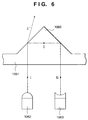
- Fig. 6 shows a positional relation among a light-transmitting prism provided on the bottom surface of an ink tank, a light emission device which emits light on the prism, and a photoreceptor which receives the emitted light.
- a prism 1060 is integrally molded to the bottom portion 1061 of the ink tank. Light emitted externally by a light emission device 1062 from the bottom of the ink tank is incident on the prism 1060.
- the incident light takes the optical path I ⁇ II' as shown in Fig. 6 and is absorbed by the ink, so that the light does not return to the photoreceptor 1063.
- the incident light is reflected by the oblique portion of the prism 1060 and takes the optical path I ⁇ II ⁇ III, then reaches the photoreceptor 1063 as shown in Fig. 6.
- ink existence/absence is detected by whether or not the light emitted by the light emission device 1062 returns to the photoreceptor 1063.
- the light emission device 1062 and photoreceptor 1063 are provided in the main body of a printing apparatus.
- the above-described ink existence/absence detection mechanism may be regarded as a rational method of realizing detection of an ink level or ink existence/absence in an ink tank at low cost.
- Japanese Patent Application Laid-Open (KOKAI) No. 7-237300 discloses a construction utilizing silicone or Teflon resin as a water repellent agent in order to avoid ink droplet attachment to the side wall surface of the ink tank or light reflector, serving as a component provided in the optical path.
- Japanese Patent Application Laid-Open (KOKAI) No. 8-187873 discloses a technique of performing surface processing such as water repellent or oil repellent processing on the inner wall surface of an ink tank, which serves as a component provided in the optical path, instead of polishing the inner wall surface of the ink tank to reduce the surface roughness thereby enlarging the contact angle between ink and the ink tank inner wall surface.
- Inks used are, for instance, an aqueous pigment ink in which pigment serving as a colorant is dispersed in water with the use of a dispersant, or an aqueous pigment ink utilizing self-dispersing pigment capable of stable dispersion without using a dispersant by reforming the surface of the pigment, or a dispersing-type ink such as micro-emulsion ink or the like in which an oil-base dye is dispersed by emulsification.
- Inventors of the present invention have used such ink, in which a colorant is dispersed, in the above-described conventional examples, and discovered that in the environment of a high temperature, even if there is no ink droplet attached to the inner portion of an ink tank, light emitted by a light emission device for ink residue detection and incident upon the ink tank does not always return to a photoreceptor.
- the inventors have discovered that, particularly in the environment of a high temperature, dispersion of the colorant becomes unstable and the colorant adsorbs to the inner wall of the ink tank.
- the colorant adsorbs to the inner wall of the ink tank, the light emitted by the light emission device for ink residue detection and incident upon the ink tank is absorbed by the colorant adsorbed to the inner wall of the ink tank.
- the present invention is made in consideration of the result of the above study, and has an object to provide an ink tank which enables accurate detection of existence/absence of liquid even when using the type of ink in which a colorant is dispersed, a cartridge including the ink tank, and a printing apparatus employing the cartridge.
- the foregoing object is attained by providing an ink tank, in which a part of a storage containing ink where a colorant is dispersed, is coated with a low surface energy processing agent including alkyl polysiloxane.
- acid be included in the low surface energy processing agent.
- the alkyl polysiloxane coated on the part of the storage be 1 to 15 ⁇ g per unit area (1 mm 2 ).
- the storage comprises a prism having a first surface which receives light emitted by an external device, and a second surface which receives the light reflected by the first surface and changes an optical path of the light received such that the optical path of the light is headed to the external device, the prism formed with a light-transmitting material, provided on a bottom portion of the storage, and protruded from the bottom portion of the storage toward an interior of the storage, wherein the prism is coated with the low surface energy processing agent.
- first surface and the second surface of the prism may be coated with the low surface energy processing agent.
- the foregoing object is attained by providing an ink tank, in which a part of a light-transmitting wall surface which forms a storage containing ink where a colorant is dispersed, has lower surface energy than other portions of the wall surface.
- a low surface energy processing agent including alkyl polysiloxane be coated on the part of the light-transmitting wall surface having low surface energy.
- the ink tank comprises a prism having a shape of substantially polygonal prism where the part of the light-transmitting wall surface constitutes a plurality of reflection surfaces having a predetermined angle with respect to an optical path of light emitted from a light source located externally at a predetermined position, wherein a side surface of the prism is coated with the low surface energy processing agent including alkyl polysiloxane.
- an ink tank comprising: a storage containing ink where a colorant is dispersed; and a residual amount detector for optically detecting ink residue contained in the storage, wherein the residual amount detector is provided on a part of a wall surface which forms the storage, and the residual amount detector is coated with a low surface energy processing agent including alkyl polysiloxane and acid so as to have lower surface energy than other portions of the wall surface where the residual amount detector is not provided.
- the storage comprises: a first chamber containing the ink only and forming a substantially enclosed space; a second chamber containing an absorbent which retains ink by absorbing ink and serves as a negative pressure generating material; and a channel where the first and second chambers are connected, wherein the first chamber includes the residual amount detector, and the second chamber includes an outlet for externally discharging liquid and an opening for introducing outside air.
- the foregoing object is attained by providing an ink tank, in which a part of a storage containing solution in which solvent includes insoluble or slightly soluble fine particles, is coated with a low surface energy processing agent including alkyl polysiloxane.
- the surface processed portion is a prism provided in the optical path of optical ink residue detection, even when using the type of ink where a colorant is dispersed, existence or absence of liquid (ink) can be accurately detected.
- the foregoing object is attained by providing a cartridge including the ink tank having aforementioned configuration, the cartridge comprising: a printhead for discharging liquid contained in the ink tank; and a holder for holding the ink tank.
- the ink tank be detachable from the holder.
- the printhead be an ink-jet printhead which performs printing by discharging ink.
- the ink-jet printhead includes heat energy transducers for generating heat energy to be applied to the ink so that the printhead discharges ink by utilizing the heat energy.
- the foregoing object is attained by providing a printing apparatus for printing an image on a print medium by using the ink tank having aforementioned configuration, the printing apparatus comprising: a printhead for performing printing by discharging ink contained in the ink tank; optical means for emitting light to the residual amount detector and receiving reflection light from the residual amount detector; detection means for detecting a residual amount of liquid contained in the ink tank based on the optical means; and control means for controlling printing operation performed by the printhead based on the detection result obtained by the detection means.
- weight or “%” indicates a percentage by weight unless specified otherwise.
- the prism according to the present invention is formed with a light-transmitting material, and comprises a surface which constructs a part of an external wall surface of a liquid container such as an ink tank, and a plurality of reflection surfaces which are different from the aforementioned surface, and whose boundary surface with contents (e.g., ink) of the storage has a predetermined angle with respect to the optical path.
- the prism is structured such that the amount of light reflected by the reflection surfaces differs depending on existence or absence of the contents of the liquid storage. Therefore, the plurality of reflection surfaces are protruded toward the interior of the container. Note that instead of the plurality of reflection surfaces, a curved surface may be provided.
- the present invention is particularly advantageous because, by coating the low surface energy processing agent not on the entire inner wall surface of the ink tank, but on the prism provided in an optical path of optical ink residue detection, it is possible to create a lower surface energy portion compared to other portions of the inner wall surface of the ink tank, which are in contact with ink. Therefore, even under a severe ink storage condition, a part of the composition of the liquid, e.g., colorant or the like, does not attach to remain on the prism surface. Accordingly, the prism is always kept in an excellent state for reflecting light, and therefore liquid existence/absence can be accurately detected.
- the low surface energy processing agent having alkyl polysiloxane it is possible to increase the adsorbent of the alkyl polysiloxane which has adsorbed to the inner wall surface of the liquid container such as an ink tank.
- Fig. 1 is a perspective view showing a schematic construction of a printing apparatus, as a typical embodiment of the present invention, which includes a printhead for performing printing in accordance with an ink-jet printing method.
- a printhead 1 connected with an ink tank 7 which supplies ink thereto construct an ink cartridge 20 as shown in Fig. 1.
- the ink cartridge 20 is configured such that the printhead 1 and ink tank 7 are separable as will be described later, an ink cartridge where a printhead and ink tank are integrated as a unit may be used.
- a prism for detecting existence/absence of ink is provided on the bottom surface of the ink tank 7. The configuration thereof will be described later.
- the printhead comprises means (e.g., electrothermal transducer or laser beam generator or the like) for generating heat energy as energy utilized upon execution of ink discharge, and employs a method which causes a change in state of ink by the heat energy, among ink-jet printing methods. According to this method, a high-density, high-precision printing operation can be attained.
- means e.g., electrothermal transducer or laser beam generator or the like
- the printhead 1 is attached to a carriage 2 in the manner such that the printhead discharges ink downward in Fig. 1. While the carriage 2 moves along a guide 3, the printhead 1 discharges ink droplets to form an image on a print medium (not shown) e.g. print paper. Note that the lateral movement (reciprocal movement) of the carriage 2 is realized by rotation of a carriage motor 4 via a timing belt 5.
- the carriage 2 has an engagement latch 6 which engages with an engagement slot 7a of the ink tank, fixing the ink tank 7 to the carriage 2.
- a print medium positioned on a platen 8 is conveyed a predetermined amount by driving a feed motor 9, and image forming for the subsequent scan is performed by moving the carriage 2 along the guide 3.
- the recovery device 10 On the right side of the main body of the printing apparatus, a recovery device 10 which performs recovery operation for maintaining a good ink discharge condition is provided.
- the recovery device 10 includes a cap 11 for capping the printhead 1, a wiper 12 for wiping the ink discharge surface of the printhead 1, and a suction pump (not shown) for sucking ink from the ink discharge nozzle of the printhead 1.
- the driving force of the feed motor 9 for conveying a print medium which is normally transmitted not only to the print medium conveyance mechanism, but also to an automatic sheet feeder (ASF) 13.
- ASF automatic sheet feeder
- an optical unit 14 consisting of an infrared LED (light emission device) 15 and phototransistor (photoreceptor) 16, is provided for detecting existence/absence of ink and existence/absence of an ink tank.
- These light emission device 15 and photoreceptor 16 are arrayed in the conveyance direction of a print medium (direction indicated by the arrow F).
- the optical unit 14 is attached to a chassis 17 of the main body of the printing apparatus. Upon attaching the ink cartridge 20 to the carriage 2, if the carriage 2 moves to the right from the position shown in Fig. 1, the ink cartridge 20 comes to the position above the optical unit 14. In this position, it is possible to detect the ink existence or absence from the bottom surface of the ink tank 7 by using the optical unit 14 (details will be described later).
- Fig. 2 is a block diagram showing the structure of a control circuit of the printing apparatus.
- reference numeral 1700 denotes an interface for inputting a print signal; 1701, an MPU; 1702, a ROM for storing control programs to be executed by the MPU 1701; and 1703, a DRAM for storing various data (aforementioned print signal, print data supplied to the printhead 1 and so on).
- Reference numeral 1704 denotes a gate array (G.A.) which controls supplying print data to the printhead 1, and also controls data transfer among the interface 1700, MPU 1701 and RAM 1703.
- Reference numeral 1705 denotes a head driver for driving the printhead 1; 1706 and 1707, motor drivers for driving the feed motor 9 and carriage motor 4 respectively.
- the interface 1700 receives a print signal
- the print signal is converted to print data for printing in between the gate array 1704 and the MPU 1701.
- the motor drivers 1706 and 1707 are driven
- the printhead 1 is driven in accordance with the print data transmitted by the head driver 1705, performing printing.
- reference numeral 1710 denotes a display portion comprising an LCD 1711 which displays various messages related to a condition of printing operation or the printing apparatus, and an LED lamp 1712 including various colors for informing the conditions of printing operation or the printing apparatus.
- the MPU 1701 controls the operation of an ink detection unit 25 which detects ink existence/absence in the ink tank 7.
- the ink detection unit 25 is described below in detail.
- Figs. 3A and 3B are block diagrams showing detailed configuration of the ink detection unit 25.
- the controller 32 outputs a pulse signal having a predetermined duty ratio (DUTY) (%) to an LED driving circuit 30 based on a control signal sent by the MPU 1701, and drives the light emission device 15 which constructs a part of the optical unit 14 in accordance with the duty ratio so as to emit infrared light upon the bottom portion of the ink tank 7.
- DUTY predetermined duty ratio
- the infrared light is reflected upon the optical prism 180 (hereinafter referred to as the prism) provided on the bottom portion of the ink tank 7 and returned to the photoreceptor 16 which constructs the rest of the optical unit 14.
- the photoreceptor 16 i.e. a phototransistor, converts the received light into an electrical signal and outputs the electrical signal to a low-pass filter (LPF) 31.
- the low-pass filter (LPF) 31 transmits only the signal having a low frequency component of the received electrical signal to the controller 32, eliminating high frequency noise.
- the controller 32 performs A/D conversion on the signal transmitted by the low-pass filter (LPF) 31, converting it into a digital signal. Then, the converted digital signal is transferred to the MPU 1701.
- the light emission device 15 is an LED emitting infrared light 28, and the photoreceptor 16 is a phototransistor for receiving infrared light 29 and outputting an electrical signal in accordance with the intensity of the received light, as shown in Fig. 3B.
- These LED and phototransistor are arranged along the conveyance direction of a print medium as shown in Fig. 1.
- Figs. 4A and 4B are perspective views showing an external appearance of a head holder 200 holding the ink tank 7 and the printhead 1.
- Fig. 4A shows the state where the ink tank 7 is detached from the head holder 200
- Fig. 4B shows the state where the ink tank 7 is held by the head holder 200.
- Fig. 5 is a sectional side view showing an internal structure of the ink tank 7.
- the ink tank 7 has a shape approximate of a rectangular parallelepiped, and has an air hole 120 on the upper wall 7U, which connects with the internal portion of the ink tank 7.
- an ink supply pipe 140 having an ink supply opening is protruded in the pipe-like form.
- the air hole 120 is sealed with a film or the like, and the ink supply pipe 140 is sealed with a cap, which is an ink supply opening sealing material.
- Reference numeral 160 denotes a resilient lever formed integrally on the outer portion of the ink tank 7, and a latch 160A is provided in the middle of the lever.
- Reference numeral 200 denotes a head holder integrating a printhead, where the aforementioned ink tank 7 is to be attached.
- ink tank 7 including three containers (7C, 7M and 7Y), each having e.g. cyan, magenta or yellow ink, are held in the head holder 200.
- the printhead 1 which discharges each of the color ink is integrally formed.
- an ink tank containing black (Bk) ink only may be attached to the head holder to construct a printhead for monochrome printing.
- a window is provided on the bottom of the head holder 200 so that an ink existence/absence detection portion, which will be described later, can detect whether or not there is residual ink, in cooperation with the optical unit 14 and ink detection unit 25.
- the printhead 1 is formed such that the plural discharge orifices of the printhead face downward (hereinafter the surface of the printhead where the plural discharge orifices are formed will be referred to as discharge-orifice surface).
- the ink tank 7 is pressed into the head holder 200 such that the ink supply pipe 140 is engaged with an ink supply pipe receptor (not shown) provided in the printhead 1 and an ink passage pipe of the printhead 1 is inserted into the ink supply pipe 140.
- the latch 160A of the lever 160 is engaged with a projection (not shown) formed in a predetermined portion of the head holder 200, and the ink tank 7 is properly inserted in the head holder 200 as shown in Fig. 4B.
- the head holder 200 integrating the ink tank 7 is attached to e.g., the carriage 2 of the printing apparatus shown in Fig. 1, and become ready for printing.
- the ink tank 7 lets air in through the air hole 120 provided on the ceiling portion of the ink tank, and the bottom portion of the ink tank 7 is connected to the ink supply opening.
- a negative-pressure-generating-material housing chamber 340 including an absorbent material 320 serving as a negative pressure generating material, and a substantial-closed liquid storage 360 containing liquid ink are separated by a partition wall 380.
- the negative-pressure-generating-material housing chamber 340 and liquid storage 360 are connected only through a channel 400 of the partition wall 380 formed near the bottom portion of the ink tank 7.
- the ink tank 7 which forms the negative-pressure-generating-material housing chamber 340
- plural ribs 420 projected into the ink tank 7 are formed, and the plural ribs are in contact with the absorbent material 320 housed in the negative-pressure-generating-material housing chamber 340 in the compressed form.
- an air buffer room 440 is formed between the upper wall 7U and the top surface of the absorbent material 320.
- the absorbent material 320 is formed with heat-compressed urethane foam, and housed in the negative-pressure-generating-material housing chamber 340 in the compressed form so as to produce a predetermined capillarity which will be described later.
- An absolute value of the pore size of the absorbent material 320 for producing the predetermined capillarity differs depending on the type of the ink used, dimension of the ink tank 7, position of the discharge-orifice surface of the printhead 1 (liquid level difference H) and so on.
- a disc-shape or cylindrical-shape pressured solid body 460 is provided in the ink supply pipe 140 forming the ink supply opening 140A.
- the pressured solid body 460 is formed with a felt made of e.g. polypropylene, and is not deformed easily by external force.
- the pressured solid body 460 is pushed into the absorbent material 320 so as to partially compress the absorbent material 320. Therefore, at the upper end portion of the ink supply pipe 140, a flange is formed around the pressured solid body 460.
- the ink tank configured with the negative-pressure-generating-material housing chamber which houses a negative-pressure material and includes the liquid supply opening and air hole, and the liquid storage which forms substantial enclosed space and has a passage connected to the negative-pressure-generating-material housing chamber
- ink is supplied to the absorbent material 320 in the negative-pressure-generating-material housing chamber 340 from the liquid storage 360 through the channel 400 of the partition wall 380.
- the pressure inside the liquid storage 360 is reduced, air from the air hole 120, coming through the negative-pressure-generating-material housing chamber 340, is supplied to the liquid storage 360 through the channel 400 provided on the partition wall 380, and the reduced pressure in the liquid storage 360 is compensated.
- ink is provided to the absorbent material 320 in accordance with the consumed amount, enabling the absorbent material 320 to keep a constant amount of ink and maintain a substantially constant negative pressure to the printhead 1. Accordingly, ink supplied to the printhead is kept stable. As the ink absorbed by the absorbent material 320 is consumed, ink in the liquid storage 360 is consumed.
- the printing apparatus can be used without concern of ink shortage.
- the prism 180 serves as the above-described ink existence/absence detection portion.
- the prism 180 is a triangular prism having a shape of an isosceles triangle whose apical angle is 90°. Therefore, if the length (a) of the base of the isosceles triangle and the length (b) of the prism in the direction perpendicular to the drawing sheet of Fig. 5 are known, the area (S) of the prism's oblique planes exposed inside the ink tank 7 is obtained by ( ⁇ 2) ⁇ a ⁇ b .
- a processing agent employed in the low surface energy processing according to the present embodiment has a composition specified in the embodiments 1 and 2 which will be described later. Although each of the embodiments 1 and 2 assumes that the density of alkyl polysiloxane is 4 weight %, the alkyl polysiloxane content in the low surface energy processing agent is in the range of 1 to 20 weight %, more preferably, 2 to 8 weight %.
- alkyl polysiloxane content is excessive, alkyl polysiloxane which does not adsorb to the surface of the prism 180 may elute in the ink and cause deterioration of ink discharge capability, whereas if the alkyl polysiloxane content is small, the surface of the prism 180 is not sufficiently processed to achieve low surface energy processing and the expected effect cannot be attained.
- 2-propanol and 2-methyl-2-propanol are employed as alcohol to serve as a solvent of alkyl polysiloxane
- the present invention is not limited to this, but may employ volatile alcohol or water soluble volatile organic solvent.
- benzenesulfonic acid as an acid substance
- a strongly acidic substance e.g., sulfuric acid, nitric acid, hydrochloric acid, aromatic sulfonic acid, aliphatic sulfonic acid or the like, may be used.
- the aforementioned low surface energy processing is performed by applying a droplet (about 3 mg) of the low surface energy processing agent having the foregoing composition onto the vertex of the prism 180 with a needle (injection needle) having a diameter of 26G, and naturally drying it after the application.
- the prism 180 used in the present embodiment is a triangular prism having a shape of an isosceles triangle whose apical angle is 90°, wherein the length (a) of the base of the isosceles triangle is 7 mm and the length (b) of the prism in the direction perpendicular to the drawing sheet of Fig. 5 is 2.6 mm.
- the amount of alkyl polysiloxane coated in the portion (in this case, prism) subjected to the low surface energy processing with the low surface energy processing agent be in the range of 1 to 15 ⁇ g/mm 2 .
- low surface energy processing using the low surface energy processing agent having alkyl polysiloxane is performed on the surface of the prism in the liquid container according to the present invention, which is provided in the optical path of optical ink existence/absence detection. Therefore, the surface energy on the prism surface becomes relatively lower than other areas of the inner wall of the storage.
- the liquid container, on which such processing has been performed is used as an ink tank for which ink existence/absence detection is performed.
- aqueous pigment ink having the following composition was used.
- -Composition of aqueous pigment ink -surface functionalized carbon black dispersion product name: Microjet C-type CW1, Orient Chemical Co.
- 5 weight % -diethylene glycol (water soluble organic solvent) 5 weight % -glycerin (water soluble organic solvent) 7 weight % -thiodiethyleneglycol (water soluble organic solvent) 7 weight % -Acetylenol EH (trade name: product of Kawaken Fine Chemicals Co., Ltd.)
- surface active agent 0.1 weight % -potassium sulfate (additive) 0.3 weight % -water remainder weight %
- the pigment employed in this embodiment is of a self-dispersing type, which does not use a dispersant and thus clogging in an ink discharge nozzle of a printhead caused by the resin forming the dispersant is improved.
- the prism of an ink tank such as that shown in Fig. 5 was subjected to the low surface energy processing which will be described below as embodiments and the ink tank was filled with aqueous pigment ink having the aforementioned composition. Then, the ink tank was stored for a month under the environment where temperature was 60°C, then ink was extracted from the ink tank, and ink residue detection was performed by using the printing apparatus having the above-described construction.
- an ink tank upon which ink residue detection was performed according to the above-described procedure with the use of the processing agent of the following embodiment 1, will be referred to as an experimental sample 1
- an ink tank upon which the detection was similarly performed with the use of the processing agent of the following embodiment 2
- an experimental sample 2 upon which the detection was similarly performed with the use of the processing agent of the following embodiment 2
- the processing agent of each embodiment was coated on the prism with a needle, as described above, for a desired amount, and naturally dried.
- the amount of alkyl polysiloxane coated on the prism was in the range of 1 to 15 ⁇ g per unit area (1 mm 2 ).
- the following two ink tanks were prepared: (1) an ink tank, whose prism was not processed by low surface energy processing, but was filled with the aqueous pigment ink having the aforementioned composition and stored under the same environment (temperature of 60°C for a month); and (2) an ink tank, whose entire inner wall surface was coated with the low surface energy processing agent A of the foregoing embodiment 1, which was then filled with the aqueous pigment ink having the aforementioned composition, and stored under the same environment (temperature of 60°C for a month).
- ink was extracted from each of the above ink tanks, and the ink residue detection was similarly performed using the printing apparatus having the above-described construction.
- the former ink tank (1) on which ink residue detection was performed according to the aforementioned procedure will be referred to as a comparative reference sample 1
- the latter ink tank (2) will be referred to as a comparative reference sample 2.
- the low surface energy processing agent not on the entire inner wall surface of the ink tank, but on a prism provided in the optical path of the optical ink residue detection, it is possible to create a lower surface energy portion compared to other portions of the inner wall of the ink tank, which are in contact with ink. Therefore, even under a severe ink storage condition, the colorant does not attach to the prism, and accurate ink existence/absence detection can be performed.
- the ink tank may contain dispersing type solution such as processing liquid or the like to be discharged on a print medium for enhancing fixation of a printed image, water-proofing a printed image, or improving image quality.
- the present embodiment may preferably employ the specific structure of a prism and sequence of ink existence/absence detection which are disclosed in Japanese Patent Application Laid-Open No. 10-323993 filed by the same patent applicant as the present invention.
- the subject upon which the low surface energy processing agent is coated is not limited to the aforementioned prism, but the ink storage portion of an ink tank which merely contains ink may be formed with a light-transmitting material and a part of the storage portion may be coated with the above-described low surface energy processing agent.
- the ink storage portion of an ink tank which merely contains ink may be formed with a light-transmitting material and a part of the storage portion may be coated with the above-described low surface energy processing agent.
- the above-described low surface energy processing may be performed on the portion of the ink tank wall surface, through which light is transmitted. In this case, even if the aforementioned aqueous pigment ink is used, the residual amount can be visually confirmed with ease.
- the prism shown in Fig. 6 is formed with a light-transmitting material, and comprises a surface which constructs a part of the external wall surface of the liquid container such as an ink tank, and a plurality of reflection surfaces which are different from the aforementioned surface, and whose boundary surface with contents (e.g., ink) of the container has a predetermined angle with respect to the optical path.
- the prism is structured such that the amount of light reflected by the reflection surfaces differs depending on existence or absence of the contents of the container.
- applying the present invention to the above-described prism is particularly advantageous because, in the case of using ink in which colorant such as aqueous pigment ink is dispersed, an ink droplet does not attach to the prism provided on the bottom of the ink tank shown in Fig. 5 when there is no ink in the ink tank. Furthermore, even if the dispersion of the colorant is unstable under the high-temperature environment, the colorant does not attach to the prism.
- the printing apparatus described in the foregoing embodiments is capable of printing at high density and high speed
- the apparatus may be used as output means of a data processing system, such as a printer serving as an output terminal such as a copy machine, facsimile, electronic typewriter, word processor, work station, or as a handy or portable printer which accompanies a personal computer, optical disk apparatus, video apparatus or the like.
- the printing apparatus is realized in the form adaptive to the unique function and usage configuration of each apparatus.
- the application range of the ink tank as the liquid container according to the present invention is not limited to a printing apparatus, but may be extended to various apparatuses such as a facsimile apparatus or a copy machine or the like. Furthermore, the present invention can be applied to a system constituted by a plurality of devices (e.g., host computer, interface, reader, printer) or to an apparatus comprising a single device (e.g., copy machine, facsimile).
- devices e.g., host computer, interface, reader, printer
- an apparatus comprising a single device e.g., copy machine, facsimile
- Ink tank which enables accurate detection of existence/absence of liquid even if a storage containing liquid such as ink is stored under a severe environment, and a cartridge including the ink tank, as well as a printing apparatus utilizing the cartridge.
- a low surface energy processing agent including alkyl polysiloxane and alcohol is coated on prism 180 provided on the bottom portion of ink tank 7, thereby performing low surface energy processing on the prism 180.
Landscapes
- Ink Jet (AREA)
- Particle Formation And Scattering Control In Inkjet Printers (AREA)
Applications Claiming Priority (4)
| Application Number | Priority Date | Filing Date | Title |
|---|---|---|---|
| JP30616098 | 1998-10-27 | ||
| JP30616098 | 1998-10-27 | ||
| JP28214099A JP3595743B2 (ja) | 1998-10-27 | 1999-10-01 | インクタンク、及び、そのインクタンクを含むカートリッジ、及び、そのカートリッジを用いる記録装置 |
| JP28214099 | 1999-10-01 |
Publications (3)
| Publication Number | Publication Date |
|---|---|
| EP0997294A2 true EP0997294A2 (de) | 2000-05-03 |
| EP0997294A3 EP0997294A3 (de) | 2001-09-12 |
| EP0997294B1 EP0997294B1 (de) | 2004-06-09 |
Family
ID=26554487
Family Applications (1)
| Application Number | Title | Priority Date | Filing Date |
|---|---|---|---|
| EP99121297A Expired - Lifetime EP0997294B1 (de) | 1998-10-27 | 1999-10-26 | Tintenbehälter, Kassette damit versehen, und mit solcher Kassette ausgerüstetes Druckwerk |
Country Status (8)
| Country | Link |
|---|---|
| US (1) | US6540314B1 (de) |
| EP (1) | EP0997294B1 (de) |
| JP (1) | JP3595743B2 (de) |
| KR (1) | KR100357681B1 (de) |
| CN (1) | CN1137030C (de) |
| AU (1) | AU747880B2 (de) |
| CA (1) | CA2287592C (de) |
| DE (1) | DE69917857T2 (de) |
Cited By (5)
| Publication number | Priority date | Publication date | Assignee | Title |
|---|---|---|---|---|
| EP1254775A3 (de) * | 2001-05-01 | 2003-09-03 | Seiko Epson Corporation | Tintenbehälter und Tintenstrahldrucker mit einem solchen Behälter |
| WO2004039592A1 (de) * | 2002-10-30 | 2004-05-13 | Kmp Print Technik Ag | Tintenpatrone zum aufbringen auf einen aufzeichnungskopf |
| DE10117885B4 (de) * | 2001-04-10 | 2007-10-18 | Tally Computerdrucker Gmbh | Tintendrucker mit einem Tintenversorgungssystem |
| EP2107971A4 (de) * | 2007-01-30 | 2011-06-29 | Hewlett Packard Development Co | Kombinierte tintenfamilienprofilierung für eine tintenpatrone |
| WO2013064006A1 (zh) * | 2011-10-31 | 2013-05-10 | 珠海天威飞马打印耗材有限公司 | 喷墨打印机 |
Families Citing this family (20)
| Publication number | Priority date | Publication date | Assignee | Title |
|---|---|---|---|---|
| JP4521981B2 (ja) * | 2000-11-09 | 2010-08-11 | キヤノン株式会社 | 繊維集合体の製造方法 |
| US6916088B2 (en) * | 2001-04-20 | 2005-07-12 | Hewlett-Packard Development Company, L.P. | Ink container configured to establish reliable fluidic connection to a receiving station |
| ATE348006T1 (de) | 2001-10-31 | 2007-01-15 | Print Rite Unicorn Image Prod | Tintenpatrone für einen drucker |
| JP4125082B2 (ja) * | 2002-09-30 | 2008-07-23 | キヤノン株式会社 | インクジェット記録ヘッドの製造方法 |
| US7360858B2 (en) * | 2003-06-30 | 2008-04-22 | Brother Kogyo Kabushiki Kaisha | Ink cartridge, detection device for cartridge identification and ink level detection, and image formation apparatus comprising thereof |
| JP2005041183A (ja) * | 2003-07-25 | 2005-02-17 | Canon Inc | 液体収容容器 |
| JP4125279B2 (ja) * | 2004-10-20 | 2008-07-30 | キヤノン株式会社 | インクタンク、該インクタンクを搭載するホルダを備えたインクジェット記録装置およびインクタンクとホルダとを備えたインクジェット記録システム |
| JP2006272902A (ja) * | 2005-03-30 | 2006-10-12 | Fuji Photo Film Co Ltd | インクタンク及びインクジェット記録装置 |
| WO2007007816A1 (ja) | 2005-07-08 | 2007-01-18 | Canon Kabushiki Kaisha | インクジェット記録装置およびインク残量検出方法 |
| US20070035596A1 (en) * | 2005-08-10 | 2007-02-15 | Lexmark International, Inc. | Ink jet cartridge |
| CN101982315A (zh) | 2005-11-29 | 2011-03-02 | 精工爱普生株式会社 | 液体喷射装置 |
| CN201721128U (zh) * | 2010-01-14 | 2011-01-26 | 珠海纳思达企业管理有限公司 | 一种喷墨打印机使用的墨盒 |
| JP5553210B2 (ja) | 2010-04-01 | 2014-07-16 | ブラザー工業株式会社 | インクジェット記録用の処理液、インクセットおよびインクジェット記録方法 |
| JP5440794B2 (ja) * | 2010-04-30 | 2014-03-12 | ブラザー工業株式会社 | インクカートリッジおよびインクジェット記録装置 |
| JP5622028B2 (ja) * | 2010-04-30 | 2014-11-12 | ブラザー工業株式会社 | インクカートリッジおよびインクジェット記録装置 |
| JP5682144B2 (ja) | 2010-05-31 | 2015-03-11 | ブラザー工業株式会社 | インクセット、インクジェット記録装置およびインクジェット記録方法 |
| JP5750838B2 (ja) | 2010-05-31 | 2015-07-22 | ブラザー工業株式会社 | インクセットおよびインクジェット記録方法 |
| JP6003148B2 (ja) * | 2012-03-28 | 2016-10-05 | セイコーエプソン株式会社 | インクカートリッジおよびインクジェット記録装置 |
| JP6362109B2 (ja) * | 2013-10-04 | 2018-07-25 | キヤノン株式会社 | インプリント装置および部品の製造方法 |
| JP7191602B2 (ja) | 2018-09-10 | 2022-12-19 | キヤノン株式会社 | 液体吐出装置 |
Citations (6)
| Publication number | Priority date | Publication date | Assignee | Title |
|---|---|---|---|---|
| JPH0789090A (ja) | 1993-08-25 | 1995-04-04 | Canon Inc | インク終了検知装置 |
| JPH07218321A (ja) | 1994-02-07 | 1995-08-18 | Fuji Xerox Co Ltd | インクタンク |
| JPH07237300A (ja) | 1994-02-09 | 1995-09-12 | Copyer Co Ltd | インクジェット記録装置 |
| JPH08112907A (ja) | 1994-10-14 | 1996-05-07 | Canon Inc | インクジェット記録装置 |
| JPH08187873A (ja) | 1995-01-13 | 1996-07-23 | Canon Inc | インク収容容器および該インク収容容器を備えるインクジェット記録装置 |
| JPH0929989A (ja) | 1995-07-14 | 1997-02-04 | Canon Inc | インク有無検出装置、インクタンク、キット、記録ユニット、記録装置、および情報処理システム |
Family Cites Families (14)
| Publication number | Priority date | Publication date | Assignee | Title |
|---|---|---|---|---|
| US4183030A (en) * | 1976-04-01 | 1980-01-08 | Minolta Camera Kabushiki Kaisha | Ink jet recording apparatus |
| GB2112715B (en) * | 1981-09-30 | 1985-07-31 | Shinshu Seiki Kk | Ink jet recording apparatus |
| AU591989B2 (en) | 1986-06-20 | 1989-12-21 | Minnesota Mining And Manufacturing Company | Block copolymer, method of making the same, diamine precursors of the same method, method of making such diamines and end products comprising the block |
| AU635562B2 (en) | 1989-09-18 | 1993-03-25 | Canon Kabushiki Kaisha | Recording head with cover |
| US5216448A (en) | 1989-09-18 | 1993-06-01 | Canon Kabushiki Kaisha | Ink jet recording head carriage and an apparatus with same |
| EP0722836B1 (de) | 1989-09-18 | 2001-04-04 | Canon Kabushiki Kaisha | Tintenstrahlgerät |
| US5136310A (en) | 1990-09-28 | 1992-08-04 | Xerox Corporation | Thermal ink jet nozzle treatment |
| DE69229509T2 (de) * | 1991-12-11 | 1999-11-25 | Canon K.K., Tokio/Tokyo | Tintenstrahlkassette und Titenbehälter |
| JP3210098B2 (ja) | 1992-10-30 | 2001-09-17 | キヤノン株式会社 | インクジェット記録装置およびインクジェット記録方法 |
| JP3397478B2 (ja) * | 1993-11-26 | 2003-04-14 | キヤノン株式会社 | インクジェットヘッド及び該インクジェットヘッドの製造方法及びインクジェット装置 |
| EP0754557B1 (de) * | 1995-07-18 | 1998-10-14 | Agfa-Gevaert N.V. | Druckkopfstruktur zur Verwendung in einem direkten elektrostatischen Druckgerät (DEP) |
| JPH10323993A (ja) | 1997-02-19 | 1998-12-08 | Canon Inc | 検出システム、該検出システムを用いる液体吐出記録装置と液体収納容器、及び、光量変化受光システム |
| US6362844B1 (en) * | 1997-10-23 | 2002-03-26 | Acer Peripherals, Inc. | Structure of a piezoelectric ink-jet printer head |
| WO2000020921A1 (en) * | 1998-10-07 | 2000-04-13 | E Ink Corporation | Capsules for electrophoretic displays and methods for making the same |
-
1999
- 1999-10-01 JP JP28214099A patent/JP3595743B2/ja not_active Expired - Fee Related
- 1999-10-25 US US09/425,013 patent/US6540314B1/en not_active Expired - Lifetime
- 1999-10-26 AU AU56098/99A patent/AU747880B2/en not_active Ceased
- 1999-10-26 DE DE69917857T patent/DE69917857T2/de not_active Expired - Lifetime
- 1999-10-26 KR KR1019990046515A patent/KR100357681B1/ko not_active Expired - Fee Related
- 1999-10-26 CA CA002287592A patent/CA2287592C/en not_active Expired - Fee Related
- 1999-10-26 EP EP99121297A patent/EP0997294B1/de not_active Expired - Lifetime
- 1999-10-27 CN CNB991231740A patent/CN1137030C/zh not_active Expired - Fee Related
Patent Citations (6)
| Publication number | Priority date | Publication date | Assignee | Title |
|---|---|---|---|---|
| JPH0789090A (ja) | 1993-08-25 | 1995-04-04 | Canon Inc | インク終了検知装置 |
| JPH07218321A (ja) | 1994-02-07 | 1995-08-18 | Fuji Xerox Co Ltd | インクタンク |
| JPH07237300A (ja) | 1994-02-09 | 1995-09-12 | Copyer Co Ltd | インクジェット記録装置 |
| JPH08112907A (ja) | 1994-10-14 | 1996-05-07 | Canon Inc | インクジェット記録装置 |
| JPH08187873A (ja) | 1995-01-13 | 1996-07-23 | Canon Inc | インク収容容器および該インク収容容器を備えるインクジェット記録装置 |
| JPH0929989A (ja) | 1995-07-14 | 1997-02-04 | Canon Inc | インク有無検出装置、インクタンク、キット、記録ユニット、記録装置、および情報処理システム |
Cited By (9)
| Publication number | Priority date | Publication date | Assignee | Title |
|---|---|---|---|---|
| DE10117885B4 (de) * | 2001-04-10 | 2007-10-18 | Tally Computerdrucker Gmbh | Tintendrucker mit einem Tintenversorgungssystem |
| EP1254775A3 (de) * | 2001-05-01 | 2003-09-03 | Seiko Epson Corporation | Tintenbehälter und Tintenstrahldrucker mit einem solchen Behälter |
| US6736496B2 (en) | 2001-05-01 | 2004-05-18 | Seiko Epson Corporation | Ink tank and ink-jet printer using the same |
| US6966642B2 (en) | 2001-05-01 | 2005-11-22 | Seiko Epson Corporation | Ink tank and ink-jet printer using the same |
| KR100545511B1 (ko) * | 2001-05-01 | 2006-01-24 | 세이코 엡슨 가부시키가이샤 | 잉크탱크 및 그것을 사용하는 잉크젯프린터 |
| WO2004039592A1 (de) * | 2002-10-30 | 2004-05-13 | Kmp Print Technik Ag | Tintenpatrone zum aufbringen auf einen aufzeichnungskopf |
| CN100360314C (zh) * | 2002-10-30 | 2008-01-09 | Kmp打印技术股份公司 | 用于安装到记录头上的墨盒 |
| EP2107971A4 (de) * | 2007-01-30 | 2011-06-29 | Hewlett Packard Development Co | Kombinierte tintenfamilienprofilierung für eine tintenpatrone |
| WO2013064006A1 (zh) * | 2011-10-31 | 2013-05-10 | 珠海天威飞马打印耗材有限公司 | 喷墨打印机 |
Also Published As
| Publication number | Publication date |
|---|---|
| DE69917857T2 (de) | 2005-08-04 |
| KR20000029298A (ko) | 2000-05-25 |
| AU747880B2 (en) | 2002-05-30 |
| EP0997294A3 (de) | 2001-09-12 |
| DE69917857D1 (de) | 2004-07-15 |
| CA2287592A1 (en) | 2000-04-27 |
| JP3595743B2 (ja) | 2004-12-02 |
| CA2287592C (en) | 2004-05-11 |
| AU5609899A (en) | 2000-05-04 |
| EP0997294B1 (de) | 2004-06-09 |
| JP2000198222A (ja) | 2000-07-18 |
| KR100357681B1 (ko) | 2002-10-19 |
| CN1137030C (zh) | 2004-02-04 |
| US6540314B1 (en) | 2003-04-01 |
| CN1252353A (zh) | 2000-05-10 |
Similar Documents
| Publication | Publication Date | Title |
|---|---|---|
| US6540314B1 (en) | Ink tank, cartridge including the ink tank, and printing apparatus using the cartridge | |
| US6705715B2 (en) | Liquid container, cartridge including liquid container, printing apparatus using cartridge and liquid-discharge printing apparatus | |
| EP0860284B1 (de) | Vorrichtung zur bestimmung von Flüssigkeitshöhe, Flüssigkeitsstrahlaufzeichnungsgerät und Flüssigkeitsbehälter | |
| US7926927B2 (en) | Liquid container and jet printing apparatus | |
| CN2810983Y (zh) | 液体容器 | |
| CN1128717C (zh) | 图像生成设备 | |
| US6419350B1 (en) | Ink tank, recording head cartridge and ink jet recording apparatus | |
| JP4101230B2 (ja) | 液体貯蔵容器および記録装置 | |
| JP2010023458A (ja) | インクタンクおよびインクジェット記録システム | |
| US20080012893A1 (en) | Image forming apparatus and image forming method | |
| JP5164570B2 (ja) | インクジェット記録装置およびインク残量検出方法 | |
| JP2011110712A (ja) | インク収納容器と再充填インク収納リサイクル容器 | |
| JP2001063085A (ja) | インクジェット記録装置 | |
| JP3584165B2 (ja) | 液体収納容器、及び、その液体収納容器を含むカートリッジ、及び、そのカートリッジを用いる記録装置 | |
| TWI302123B (en) | Ink jet printing apparatus and ink tank for the same | |
| JP2007001210A (ja) | 液体収納容器 | |
| JP2000043282A (ja) | 液体収納容器、及び、その液体収納容器を含むカートリッジ、及び、そのカートリッジを用いる記録装置 | |
| JP2001253085A (ja) | インクジェット式記録装置 | |
| JP2004202796A (ja) | 液体収納容器 | |
| JP3501663B2 (ja) | 液体収納容器、及び、その液体収納容器を含むカートリッジ、及び、そのカートリッジを用いる記録装置、及び、液体吐出記録装置 | |
| JP2004009447A (ja) | インクジェット記録装置 | |
| JP2001199079A (ja) | インクジェット式記録装置 |
Legal Events
| Date | Code | Title | Description |
|---|---|---|---|
| PUAI | Public reference made under article 153(3) epc to a published international application that has entered the european phase |
Free format text: ORIGINAL CODE: 0009012 |
|
| AK | Designated contracting states |
Kind code of ref document: A2 Designated state(s): AT BE CH CY DE DK ES FI FR GB GR IE IT LI LU MC NL PT SE Kind code of ref document: A2 Designated state(s): DE ES FR GB IT NL |
|
| AX | Request for extension of the european patent |
Free format text: AL;LT;LV;MK;RO;SI |
|
| PUAL | Search report despatched |
Free format text: ORIGINAL CODE: 0009013 |
|
| AK | Designated contracting states |
Kind code of ref document: A3 Designated state(s): AT BE CH CY DE DK ES FI FR GB GR IE IT LI LU MC NL PT SE |
|
| AX | Request for extension of the european patent |
Free format text: AL;LT;LV;MK;RO;SI |
|
| 17P | Request for examination filed |
Effective date: 20020123 |
|
| AKX | Designation fees paid |
Free format text: DE ES FR GB IT NL |
|
| 17Q | First examination report despatched |
Effective date: 20020625 |
|
| GRAP | Despatch of communication of intention to grant a patent |
Free format text: ORIGINAL CODE: EPIDOSNIGR1 |
|
| GRAS | Grant fee paid |
Free format text: ORIGINAL CODE: EPIDOSNIGR3 |
|
| GRAA | (expected) grant |
Free format text: ORIGINAL CODE: 0009210 |
|
| AK | Designated contracting states |
Kind code of ref document: B1 Designated state(s): DE ES FR GB IT NL |
|
| PG25 | Lapsed in a contracting state [announced via postgrant information from national office to epo] |
Ref country code: NL Free format text: LAPSE BECAUSE OF FAILURE TO SUBMIT A TRANSLATION OF THE DESCRIPTION OR TO PAY THE FEE WITHIN THE PRESCRIBED TIME-LIMIT Effective date: 20040609 |
|
| REG | Reference to a national code |
Ref country code: GB Ref legal event code: FG4D |
|
| REF | Corresponds to: |
Ref document number: 69917857 Country of ref document: DE Date of ref document: 20040715 Kind code of ref document: P |
|
| PG25 | Lapsed in a contracting state [announced via postgrant information from national office to epo] |
Ref country code: ES Free format text: LAPSE BECAUSE OF FAILURE TO SUBMIT A TRANSLATION OF THE DESCRIPTION OR TO PAY THE FEE WITHIN THE PRESCRIBED TIME-LIMIT Effective date: 20040920 |
|
| NLV1 | Nl: lapsed or annulled due to failure to fulfill the requirements of art. 29p and 29m of the patents act | ||
| ET | Fr: translation filed | ||
| PLBE | No opposition filed within time limit |
Free format text: ORIGINAL CODE: 0009261 |
|
| STAA | Information on the status of an ep patent application or granted ep patent |
Free format text: STATUS: NO OPPOSITION FILED WITHIN TIME LIMIT |
|
| 26N | No opposition filed |
Effective date: 20050310 |
|
| PGFP | Annual fee paid to national office [announced via postgrant information from national office to epo] |
Ref country code: FR Payment date: 20131028 Year of fee payment: 15 |
|
| PGFP | Annual fee paid to national office [announced via postgrant information from national office to epo] |
Ref country code: IT Payment date: 20131007 Year of fee payment: 15 |
|
| REG | Reference to a national code |
Ref country code: FR Ref legal event code: ST Effective date: 20150630 |
|
| PG25 | Lapsed in a contracting state [announced via postgrant information from national office to epo] |
Ref country code: IT Free format text: LAPSE BECAUSE OF NON-PAYMENT OF DUE FEES Effective date: 20141026 Ref country code: FR Free format text: LAPSE BECAUSE OF NON-PAYMENT OF DUE FEES Effective date: 20141031 |
|
| PGFP | Annual fee paid to national office [announced via postgrant information from national office to epo] |
Ref country code: GB Payment date: 20171101 Year of fee payment: 19 |
|
| PGFP | Annual fee paid to national office [announced via postgrant information from national office to epo] |
Ref country code: DE Payment date: 20171229 Year of fee payment: 19 |
|
| REG | Reference to a national code |
Ref country code: DE Ref legal event code: R119 Ref document number: 69917857 Country of ref document: DE |
|
| GBPC | Gb: european patent ceased through non-payment of renewal fee |
Effective date: 20181026 |
|
| PG25 | Lapsed in a contracting state [announced via postgrant information from national office to epo] |
Ref country code: DE Free format text: LAPSE BECAUSE OF NON-PAYMENT OF DUE FEES Effective date: 20190501 |
|
| PG25 | Lapsed in a contracting state [announced via postgrant information from national office to epo] |
Ref country code: GB Free format text: LAPSE BECAUSE OF NON-PAYMENT OF DUE FEES Effective date: 20181026 |