EP0994469A2 - Appareil d'enregistrement/reproduction pour support d'enregistrement optique et tête optique - Google Patents
Appareil d'enregistrement/reproduction pour support d'enregistrement optique et tête optique Download PDFInfo
- Publication number
- EP0994469A2 EP0994469A2 EP99120246A EP99120246A EP0994469A2 EP 0994469 A2 EP0994469 A2 EP 0994469A2 EP 99120246 A EP99120246 A EP 99120246A EP 99120246 A EP99120246 A EP 99120246A EP 0994469 A2 EP0994469 A2 EP 0994469A2
- Authority
- EP
- European Patent Office
- Prior art keywords
- recording
- optical
- information
- reproducing apparatus
- recording medium
- Prior art date
- Legal status (The legal status is an assumption and is not a legal conclusion. Google has not performed a legal analysis and makes no representation as to the accuracy of the status listed.)
- Withdrawn
Links
Images


Classifications
-
- G—PHYSICS
- G11—INFORMATION STORAGE
- G11B—INFORMATION STORAGE BASED ON RELATIVE MOVEMENT BETWEEN RECORD CARRIER AND TRANSDUCER
- G11B7/00—Recording or reproducing by optical means, e.g. recording using a thermal beam of optical radiation by modifying optical properties or the physical structure, reproducing using an optical beam at lower power by sensing optical properties; Record carriers therefor
- G11B7/12—Heads, e.g. forming of the optical beam spot or modulation of the optical beam
- G11B7/135—Means for guiding the beam from the source to the record carrier or from the record carrier to the detector
- G11B7/1372—Lenses
- G11B7/1378—Separate aberration correction lenses; Cylindrical lenses to generate astigmatism; Beam expanders
-
- G—PHYSICS
- G11—INFORMATION STORAGE
- G11B—INFORMATION STORAGE BASED ON RELATIVE MOVEMENT BETWEEN RECORD CARRIER AND TRANSDUCER
- G11B7/00—Recording or reproducing by optical means, e.g. recording using a thermal beam of optical radiation by modifying optical properties or the physical structure, reproducing using an optical beam at lower power by sensing optical properties; Record carriers therefor
- G11B7/08—Disposition or mounting of heads or light sources relatively to record carriers
- G11B7/09—Disposition or mounting of heads or light sources relatively to record carriers with provision for moving the light beam or focus plane for the purpose of maintaining alignment of the light beam relative to the record carrier during transducing operation, e.g. to compensate for surface irregularities of the latter or for track following
-
- G—PHYSICS
- G11—INFORMATION STORAGE
- G11B—INFORMATION STORAGE BASED ON RELATIVE MOVEMENT BETWEEN RECORD CARRIER AND TRANSDUCER
- G11B7/00—Recording or reproducing by optical means, e.g. recording using a thermal beam of optical radiation by modifying optical properties or the physical structure, reproducing using an optical beam at lower power by sensing optical properties; Record carriers therefor
- G11B7/12—Heads, e.g. forming of the optical beam spot or modulation of the optical beam
- G11B7/125—Optical beam sources therefor, e.g. laser control circuitry specially adapted for optical storage devices; Modulators, e.g. means for controlling the size or intensity of optical spots or optical traces
- G11B7/127—Lasers; Multiple laser arrays
- G11B7/1275—Two or more lasers having different wavelengths
-
- G—PHYSICS
- G11—INFORMATION STORAGE
- G11B—INFORMATION STORAGE BASED ON RELATIVE MOVEMENT BETWEEN RECORD CARRIER AND TRANSDUCER
- G11B7/00—Recording or reproducing by optical means, e.g. recording using a thermal beam of optical radiation by modifying optical properties or the physical structure, reproducing using an optical beam at lower power by sensing optical properties; Record carriers therefor
- G11B7/12—Heads, e.g. forming of the optical beam spot or modulation of the optical beam
- G11B7/135—Means for guiding the beam from the source to the record carrier or from the record carrier to the detector
- G11B7/1365—Separate or integrated refractive elements, e.g. wave plates
- G11B7/1369—Active plates, e.g. liquid crystal panels or electrostrictive elements
-
- G—PHYSICS
- G11—INFORMATION STORAGE
- G11B—INFORMATION STORAGE BASED ON RELATIVE MOVEMENT BETWEEN RECORD CARRIER AND TRANSDUCER
- G11B7/00—Recording or reproducing by optical means, e.g. recording using a thermal beam of optical radiation by modifying optical properties or the physical structure, reproducing using an optical beam at lower power by sensing optical properties; Record carriers therefor
- G11B7/12—Heads, e.g. forming of the optical beam spot or modulation of the optical beam
- G11B7/135—Means for guiding the beam from the source to the record carrier or from the record carrier to the detector
- G11B7/1372—Lenses
-
- G—PHYSICS
- G11—INFORMATION STORAGE
- G11B—INFORMATION STORAGE BASED ON RELATIVE MOVEMENT BETWEEN RECORD CARRIER AND TRANSDUCER
- G11B7/00—Recording or reproducing by optical means, e.g. recording using a thermal beam of optical radiation by modifying optical properties or the physical structure, reproducing using an optical beam at lower power by sensing optical properties; Record carriers therefor
- G11B7/12—Heads, e.g. forming of the optical beam spot or modulation of the optical beam
- G11B7/135—Means for guiding the beam from the source to the record carrier or from the record carrier to the detector
- G11B7/1392—Means for controlling the beam wavefront, e.g. for correction of aberration
- G11B7/13925—Means for controlling the beam wavefront, e.g. for correction of aberration active, e.g. controlled by electrical or mechanical means
- G11B7/13927—Means for controlling the beam wavefront, e.g. for correction of aberration active, e.g. controlled by electrical or mechanical means during transducing, e.g. to correct for variation of the spherical aberration due to disc tilt or irregularities in the cover layer thickness
-
- G—PHYSICS
- G11—INFORMATION STORAGE
- G11B—INFORMATION STORAGE BASED ON RELATIVE MOVEMENT BETWEEN RECORD CARRIER AND TRANSDUCER
- G11B7/00—Recording or reproducing by optical means, e.g. recording using a thermal beam of optical radiation by modifying optical properties or the physical structure, reproducing using an optical beam at lower power by sensing optical properties; Record carriers therefor
- G11B7/12—Heads, e.g. forming of the optical beam spot or modulation of the optical beam
- G11B7/14—Heads, e.g. forming of the optical beam spot or modulation of the optical beam specially adapted to record on, or to reproduce from, more than one track simultaneously
-
- G—PHYSICS
- G11—INFORMATION STORAGE
- G11B—INFORMATION STORAGE BASED ON RELATIVE MOVEMENT BETWEEN RECORD CARRIER AND TRANSDUCER
- G11B7/00—Recording or reproducing by optical means, e.g. recording using a thermal beam of optical radiation by modifying optical properties or the physical structure, reproducing using an optical beam at lower power by sensing optical properties; Record carriers therefor
- G11B2007/0003—Recording, reproducing or erasing systems characterised by the structure or type of the carrier
- G11B2007/0009—Recording, reproducing or erasing systems characterised by the structure or type of the carrier for carriers having data stored in three dimensions, e.g. volume storage
- G11B2007/0013—Recording, reproducing or erasing systems characterised by the structure or type of the carrier for carriers having data stored in three dimensions, e.g. volume storage for carriers having multiple discrete layers
-
- G—PHYSICS
- G11—INFORMATION STORAGE
- G11B—INFORMATION STORAGE BASED ON RELATIVE MOVEMENT BETWEEN RECORD CARRIER AND TRANSDUCER
- G11B7/00—Recording or reproducing by optical means, e.g. recording using a thermal beam of optical radiation by modifying optical properties or the physical structure, reproducing using an optical beam at lower power by sensing optical properties; Record carriers therefor
- G11B7/08—Disposition or mounting of heads or light sources relatively to record carriers
- G11B7/09—Disposition or mounting of heads or light sources relatively to record carriers with provision for moving the light beam or focus plane for the purpose of maintaining alignment of the light beam relative to the record carrier during transducing operation, e.g. to compensate for surface irregularities of the latter or for track following
- G11B7/0908—Disposition or mounting of heads or light sources relatively to record carriers with provision for moving the light beam or focus plane for the purpose of maintaining alignment of the light beam relative to the record carrier during transducing operation, e.g. to compensate for surface irregularities of the latter or for track following for focusing only
Definitions
- the present invention relates to a recording/reproducing apparatus for an optical information recording medium having a plurality of recording layers in which information is recorded or from which information is reproduced by irradiation of laser beams or the like.
- optical information recording media Because of their large-capacity and high-density memory, optical information recording media have been receiving attention. The development of an erasable type from which information can be erased and on which information can be rewritten has been pursued at present.
- the erasable-type optical information recording media include one in which thin films whose phase is changed between an amorphous state and a crystalline state are used as recording layers and information is recorded and erased by thermal energy through the irradiation of laser beams.
- an alloy film containing Ge, Sb, Te, In, or the like as the main component for example, a Ge-Sb-Te alloy film.
- information is recorded by formation of marks through partial change in a recording layer into the amorphous state and information is erased by crystallization of the amorphous marks.
- the amorphous state can be obtained by heating the recording layer to its melting point or more and then cooling it at a speed of at least a fixed value.
- the crystallization can be carried out by heating of the recording layer to a temperature between its crystallization temperature and its melting point.
- JP-A-3-157816 describes a recording medium having a plurality of recording layers and transparent separating layers provided between the recording layers and a recording/reproducing apparatus for the same.
- first recording/reproducing apparatus described in the above-mentioned JP-A-3-157816, light is focused on an intended recording layer out of the plurality of recording layers in the medium by inserting a parallel plate whose thickness is varied depending on the intended recording layer, between an objective lens and a medium.
- the second recording/reproducing apparatus in JP-A-3-157816 comprises one objective lens and a plurality of light sources that emit lights with different wavelengths.
- focal positions of respective lights irradiated from the plurality of light sources onto a medium are varied from one another.
- the lights are focused on a plurality of recording layers respectively at the same time.
- a plurality of light sources that emit lights with the same wavelength are positioned so as to have different position relationships from one another with respect to an optical system and thus the focal positions of respective lights irradiated from the plurality of light sources onto a medium are varied from one another. Consequently, the lights are focused on a plurality of recording layers respectively at the same time.
- the demand for the increase in capacity can be satisfied.
- the other demand for the increase in speed has not been satisfied sufficiently since information cannot be reproduced from or recorded in a plurality of recording layers simultaneously and therefore the data rate has been the same as in the case of using a medium with a single recording layer.
- a common shifting of the objective lens is used for focusing lights irradiated from the plurality of light sources. Therefore, the relative relationships among the focal positions of lights irradiated from respective light sources are continuously constant. Consequently, when the thickness of transparent separating layers in the recording medium is different from a designed value or is uneven, it was difficult to focus the lights on the plurality of recording layers precisely, which has been a problem.
- the present invention solves the above-mentioned conventional problems. It is an object of the present invention to provide a recording/reproducing apparatus for an optical information recording medium and an optical head that can reproduce information from and record information in a plurality of recording layers simultaneously and can enable high-speed information transfer.
- a recording/reproducing apparatus of the present invention is characterized in that a plurality of optical heads are positioned on the same side with respect to a recording medium and each of the plurality of optical heads comprises an independent light source and optical system. Consequently, information can be reproduced from or recorded in a plurality of recording layers simultaneously, thus enabling the high-speed information transfer.
- the plurality of optical heads are arranged at almost the same radial positions (i.e. at positions almost equally spaced from a rotation center).
- simultaneous reproduction of information from or simultaneous recording of information in a plurality of layers is facilitated in a recording system referred to as "Zone-CAV" presently employed in DVD-RAM or the like in which rotation speed is changed per recording zone on a recording medium to obtain almost constant linear velocity.
- Zone-CAV recording system
- the apparatus can be simplified and decreased in size.
- optimum substrate thicknesses for minimizing spot diameters of lights that are emitted from the plurality of optical heads and then are focused through a substrate are set to be different from one another beforehand, thus improving the signal quality in reproducing information from or recording information in an intended recording layer with each optical head and stability in a control system for focusing, tracking, or the like of the optical heads.
- Another recording/reproducing apparatus of the present invention comprises one objective lens and a plurality of light sources.
- the recording/reproducing apparatus is characterized in that with respect to at least one light source, an optical path correction system having a function of controlling a focal position is provided on an optical path unique to the light source.
- An optical head of the present invention comprises one objective lens and a plurality of light sources.
- the optical head is characterized in that with respect to at least one light source, an optical path correction system having a function of controlling a focal position is provided on an optical path unique to the light source. Therefore, while light irradiated from one light source is focused on a specific recording layer by shifting of the objective lens, light irradiated from another light source can be focused on another recording layer by the optical path correction system. In other words, even when the thickness of transparent separating layers in a recording medium is different from a designed value or is uneven, lights irradiated from the plurality of light sources can be focused precisely on respective intended recording layers simultaneously.
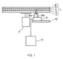
- FIG. 1 is a structural view of a recording/reproducing apparatus for an optical information recording medium in the first embodiment of the present invention.
- an information recording medium 1 with two recording layers has been loaded in the apparatus.
- the information recording medium 1 comprises: a transparent substrate 2 made of polycarbonate with a thickness of about 0.58 mm; a first recording layer 3 formed of a translucent layer with a thickness of about 10 nm; a transparent separating layer 4 with a thickness of about 0.04 mm; a second recording layer 5, and a protective layer 6.
- the information recording medium 1 is obtained by forming the first recording layer 3, the transparent separating layer 4, and the second recording layer 5 on the transparent substrate 2 sequentially and then providing the protective layer 6 thereon.
- the recording/reproducing apparatus comprises: a spindle motor 7; two optical heads 8a and 8b; a carrier table 9 on which the optical heads 8a and 8b have been installed; a shifting system 10 for moving the carrier table 9 to a desired position; and a controller 11.
- FIG. 2 shows a configuration of the optical heads 8a and 8b.
- light emitted from a light source 12 of a semiconductor laser passes through a collimator lens 13, a beam splitter 14, a 1/4 wave plate 15, and an objective lens 16 to be converged on the recording medium 1.
- the converged light is focused on a recording layer in the recording medium 1 by adjusting the position of the objective lens 16, for example, by a voice coil 17.
- the light reflected from the recording layer passes through the objective lens 16 and the 1/4 wave plate 15 again, is reflected by the beam splitter 14, and then enters into a detector 18, thus being converted to an electric signal.
- the optical heads 8a and 8b are arranged so as to be at almost the same radial positions with respect to the spindle motor 7 (i.e. at positions almost equally spaced from a rotation center).
- the lights irradiated from respective optical heads 8a and 8b are focused on the recording layers 3 and 5 in the above-mentioned manner. Consequently, information is reproduced from or recorded in the recording layers 3 and 5 simultaneously, thus enabling high-speed information transfer. In other words, information can be recorded or reproduced at a speed twice as fast as that in a conventional method.
- a carrying mechanism and a control circuit for the carrying mechanism may be equivalent to those employed when one optical head is used.
- the increase in apparatus size caused by providing two optical heads can be diminished, which is an advantage.
- the optical heads 8a and 8b are designed so that optimum substrate thicknesses for minimizing spot diameters of lights that are irradiated from the optical heads 8a and 8b and then are focused through the substrate are different from each other according to the distance to the recording layers 3 and 5.
- their optical systems are set so that the above-mentioned optimum substrate thicknesses are 0.58 mm and 0.62 mm, respectively. Therefore, when the optical head 8a irradiates light onto the recording medium 1, the light is focused at a position that the light reaches after passing through the substrate with a thickness of 0.58 mm, i.e. on the recording layer 3, without aberration.
- the optical head 8b irradiates light onto the recording medium 1
- the light is focused at a position that the light reaches after passing through the 0.58-mm substrate, the 10-nm recording layer 3, and the 0.04-mm transparent separating layer, i.e. on the recording layer 5, without aberration. Consequently, the following advantages can be obtained. That is, in addition to the improvement in signal quality in reproducing information from or recording information in respective intended recording layers with respective optical heads, the tolerance to the variation in thickness of the transparent separating layers increases.
- information was reproduced from or recorded in the two recording layers simultaneously.
- the lights irradiated from the optical heads being focused on the two recording layers simultaneously, information can be reproduced from or recorded in the two recording layers not simultaneously but sequentially without a break by suitably switching the optical head to be used.
- FIG. 1 with the lights irradiated from the optical heads 8a and 8b being focused on the recording layers 3 and 5 respectively, information in the recording layer 3 is reproduced first while the optical head 8b is in a standby state. Then, the optical head to be used is switched to the optical head 8b and information in the recording layer 5 is reproduced.
- the description was directed to the combination of the recording/reproducing apparatus having two optical heads and the recording medium having two recording layers.
- the number of optical heads may be three or more and is not required to be the same as that of recording layers in a recording medium.
- the data rate can be increased by a factor of n .
- the data rate can be quadrupled.
- the optical heads are placed on a plurality of carrier tables, the same effect can be obtained, although the complexity of the configuration increases.
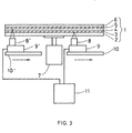
- FIG. 3 is a structural view of a recording/reproducing apparatus for an optical information recording medium in a second embodiment of the present invention.
- the recording/reproducing apparatus has the same configuration as that in the first embodiment shown in FIG. 1 except for the optical heads and shifting systems.
- a recording medium 1 has two recording layers 3 and 5 as described in the first embodiment. In each recording layer, a guide groove for tracking and address information that are not shown in the figure have been formed beforehand.
- the guide groove in the recording layer 3 is formed spirally from the inner radius toward the outer radius of the recording medium 1.
- the guide groove in the recording layer 5 is formed spirally from the outer radius toward the inner radius of the recording medium 1.
- An optical head 8 reproduces information from or records information in the recording layer 3 and at the same time an optical head 8' reproduces information from or records information in the recording layer 5.
- a spindle motor 7 rotates continuously at a constant rotation speed.
- Numerals 9 and 9' indicate carrier tables on which the optical heads 8 and 8' have been placed respectively, and numerals 10 and 10' represent shifting systems thereof. In this case, the two optical heads 8 and 8' are positioned so that the total of linear velocities at their respective positions in the recording medium is almost constant.
- the optical head 8 records or reproduces information at the innermost radius of the recording medium 1 and at the same time the optical head 8' records or reproduces information at the outermost radius of the recording medium 1.
- a reference clock for a recording signal is varied according to the linear velocity so that almost constant recording density can be obtained.
- the total of data rates obtained by the two optical heads is almost constant.
- the data rate can be doubled as a system.
- the rotation speed of the spindle is continuously constant and is not required to be changed corresponding to the positions of the optical heads. Therefore, not only the high data rate can be obtained, but also access speed can be increased.
- the description was directed to the combination of the recording/reproducing apparatus having two optical heads and the recording medium having two recording layers.
- the number of optical heads may be four or more as long as it is an even number, and it is not necessary to be the same as that of recording layers in a recording medium.
- the apparatus can be decreased in size.
- the recording/reproducing apparatus for an optical information recording medium in a third embodiment of the present invention has the same configuration as that in the first embodiment shown in FIG. 1 except for an optical head.
- FIG. 4 shows the configuration of the optical head.
- the optical head is provided with light sources 19 and 20 of semiconductor lasers that emit lights with different wavelengths from each other, for example, 680 nm and 640 nm, respectively.
- a mirror 27 with wavelength-selectivity transmits light with a wavelength of 680 nm emitted from the light source 19 and reflects light with a wavelength of 640 nm emitted from the light source 20.
- the light emitted from the light source 20 passes through a collimator lens 22, a beam splitter 24, and a 1/4 wave plate 26 and is reflected by the mirror 27.
- the reflected light passes through an objective lens 28 and thus is converged on a recording layer 3.
- the light reflected from the recording layer 3 passes through the objective lens 28 again, is reflected by the mirror 27, passes though the 1/4 wave plate 26, is reflected by the beam splitter 24, and then enters into a detector 32, thus being converted to an electric signal.
- the light emitted from the light source 19 passes through an optical path correction system 30 formed of a liquid crystal device, a collimator lens 21, a beam splitter 23, and a 1/4 wave plate 25, is transmitted by the mirror 27, and passes through the objective lens 28, thus being converged on a recording layer 5.
- the light reflected from the recording layer 5 passes through the objective lens 28 again, is transmitted by the mirror 27, passes through the 1/4 wave plate 25, is reflected by the beam splitter 23, and then enters into a detector 31, thus being converted to an electric signal.
- the light emitted from the light source 20 is focused on the recording layer 3 in a recording medium 1 having two recording layers through adjustment of the position of the objective lens 28, for example, by a voice coil 29.
- the light reflected from the recording layer 3 is detected by the detector 32 and then a focus error signal is generated.
- the voice coil 29 is controlled based on this focus error signal.
- the shift in position of recording layer 5 due to wobbling of the recording medium 1 can be compensated by focusing of the light emitted from the light source 20 on the recording layer 3 as described above, since the shift in position of recording layer 5 is common to that of the recording layer 3.
- the recording/reproducing apparatus of the present embodiment corrects the aberration by detecting the light reflected from the recording layer 5 by the detector 31 to generate a focus error signal and operating the optical path correction system 30 based on this focus error signal to change light intensity and phase distribution. Then the recording/reproducing apparatus adjusts the focal position corresponding to the unevenness in thickness of the transparent separating layer 4 or the like, thus enabling the light emitted from the light source 19 to be focused on the recording layer 5 precisely.
- the light irradiated from one light source can be focused on a specific recording layer by shifting of the objective lens and at the same time the light irradiated from the other light source can be focused on the other recording layer by the optical path correction system.
- the thickness of the transparent separating layer 4 in the recording medium is different from a designed value or is uneven, lights irradiated from a plurality of light sources can be focused precisely on respective intended recording layers simultaneously.
- the focal distance of light with a short wavelength is shorter than that of light with a long wavelength.
- the design of the optical system is facilitated by setting the wavelength of the light irradiated from the light source 20 used for recording of information in or reproduction of information from the recording layer 3 positioned near to the plane of incidence of light in the recording medium to be shorter than that of the light irradiated from the light source 19 used for recording of information in or reproduction of information from the recording layer 5 positioned far from the plane of incidence of light.
- the liquid crystal device was used as the optical path correction system.
- the optical path correction system may be formed of a lens provided with a movable mechanism by, for example, a piezoelectric element or the like and may be placed between the collimator lens 21 and the beam splitter 23 as long as it is placed on an optical path unique to the light emitted from the light source 19.
- the optical path correction system 30 on the optical path unique to the light irradiated from the light source 20
- the light irradiated from the light source 19 may be focused on the recording layer 5 through adjustment of the position of the objective lens 28 by the voice coil 29 and the light irradiated from the light source 20 may be focused through adjustment by the optical path correction system 30.
- the wavelength of the light irradiated from the light source 20 used for recording of information in or reproduction of information from the recording layer 3 positioned near to the plane of incidence of light in the recording medium was shorter than that of the light irradiated from the light source 19 used for recording of information in or reproduction of information from the recording layer 5 positioned far from the plane of incidence of light.
- the wavelength of the light irradiated from the light source 20 may be longer than that of the light irradiated from the light source 19, when the recording layer 3 near to the plane of incidence of light in the recording medium intended for recording and reproduction of information is formed of a material in which transmittance of light decreases as the wavelength of the light becomes longer, or the like.
- the number of light sources may be three or more and is not required to be the same as that of the recording layers in a recording medium.
- semiconductor lasers that irradiate lights with different wavelengths from each other were used as the light sources.
- the light sources that emit lights with the same wavelength may be used in the case of using another means for separating reflected lights from the recording medium that are emitted from different light sources, for example, a means for allowing the positions where images are formed by the lights reflected from the recording medium at the detector region to be different by setting optical paths of the lights emitted from the light sources 19 and 20 to have different angles from each other.
- the wavelengths of lights emitted from the light sources and a numerical aperture of the objective lens are designed suitably according to the optical characteristics of the recording layers in the recording medium intended for recording and reproduction of information, the thickness of the substrate, and the like.
- the descriptions were directed to the application for increasing the data rate using a plurality of heads in the same state, for example, in a recording mode or in a reproducing mode, and the application for improving the continuity by selecting one head to record information and setting the other head to be in a standby state.
- the present invention is not limited to those.
- independent radial shifting systems are provided, operations of recording and reproduction that are completely independent from each other can be carried out simultaneously by placing one head in a recording mode and the other in a reproducing mode.
- the present invention may be applied as a variable time-shift apparatus in which one head records information and at the same time the other head reproduces the information that was recorded on a recording track a short while ago, which is referred to as delayed reproduction.
- the present invention has a wide range of applicability.
- a disk is used as an information recording medium.
- the present invention can be applied to recording/reproducing apparatuses for multilayered media with other shapes such as a card-like shape or the like.
- the recording/reproducing apparatus for an optical information recording medium and the optical heads of the present invention even when the thickness of transparent separating layers in a recording medium with a plurality of recording layers is different from a designed value or is uneven, lights irradiated from a plurality of light sources can be focused precisely on respective intended different recording layers simultaneously. Consequently, information can be reproduced from or recorded in a plurality of recording layers simultaneously, thus enabling the high-speed information transfer.
Landscapes
- Physics & Mathematics (AREA)
- Optics & Photonics (AREA)
- Chemical & Material Sciences (AREA)
- Crystallography & Structural Chemistry (AREA)
- Optical Recording Or Reproduction (AREA)
- Optical Head (AREA)
Priority Applications (2)
| Application Number | Priority Date | Filing Date | Title |
|---|---|---|---|
| EP03020644A EP1385153A1 (fr) | 1998-10-13 | 1999-10-11 | Appareil d'enregistrement/reproduction pour support d'enregistrement optique et tête optique |
| EP03020643A EP1385152B1 (fr) | 1998-10-13 | 1999-10-11 | Appareil d'enregistrement/reproduction pour support d'enregistrement optique et tête optique |
Applications Claiming Priority (2)
| Application Number | Priority Date | Filing Date | Title |
|---|---|---|---|
| JP29034998 | 1998-10-13 | ||
| JP29034998 | 1998-10-13 |
Related Child Applications (1)
| Application Number | Title | Priority Date | Filing Date |
|---|---|---|---|
| EP03020643A Division EP1385152B1 (fr) | 1998-10-13 | 1999-10-11 | Appareil d'enregistrement/reproduction pour support d'enregistrement optique et tête optique |
Publications (2)
| Publication Number | Publication Date |
|---|---|
| EP0994469A2 true EP0994469A2 (fr) | 2000-04-19 |
| EP0994469A3 EP0994469A3 (fr) | 2001-09-19 |
Family
ID=17754905
Family Applications (3)
| Application Number | Title | Priority Date | Filing Date |
|---|---|---|---|
| EP03020644A Withdrawn EP1385153A1 (fr) | 1998-10-13 | 1999-10-11 | Appareil d'enregistrement/reproduction pour support d'enregistrement optique et tête optique |
| EP03020643A Expired - Lifetime EP1385152B1 (fr) | 1998-10-13 | 1999-10-11 | Appareil d'enregistrement/reproduction pour support d'enregistrement optique et tête optique |
| EP99120246A Withdrawn EP0994469A3 (fr) | 1998-10-13 | 1999-10-11 | Appareil d'enregistrement/reproduction pour support d'enregistrement optique et tête optique |
Family Applications Before (2)
| Application Number | Title | Priority Date | Filing Date |
|---|---|---|---|
| EP03020644A Withdrawn EP1385153A1 (fr) | 1998-10-13 | 1999-10-11 | Appareil d'enregistrement/reproduction pour support d'enregistrement optique et tête optique |
| EP03020643A Expired - Lifetime EP1385152B1 (fr) | 1998-10-13 | 1999-10-11 | Appareil d'enregistrement/reproduction pour support d'enregistrement optique et tête optique |
Country Status (6)
| Country | Link |
|---|---|
| US (2) | US7075870B2 (fr) |
| EP (3) | EP1385153A1 (fr) |
| KR (2) | KR100374746B1 (fr) |
| CN (2) | CN100336121C (fr) |
| DE (1) | DE69931079T2 (fr) |
| TW (1) | TW540038B (fr) |
Cited By (3)
| Publication number | Priority date | Publication date | Assignee | Title |
|---|---|---|---|---|
| EP1014347A2 (fr) * | 1998-12-21 | 2000-06-28 | Deutsche Thomson-Brandt Gmbh | Appareil de reproduction ou d'enregistrement d'un support d'enregistrement optique avec plusieurs couches d'enregistrement d'informations |
| EP1244102A2 (fr) * | 2001-03-21 | 2002-09-25 | Konica Corporation | Dispositif de lecture optique, système optique convergeant d'un dispositif de lecture optique, et procédé d'enregistrement et de reproduction d'informations optiques |
| EP1526520A2 (fr) * | 2003-10-20 | 2005-04-27 | Pioneer Corporation | Dispositif capteur optique et appareil de reproduction d'un milieu d'enregistrement optique |
Families Citing this family (17)
| Publication number | Priority date | Publication date | Assignee | Title |
|---|---|---|---|---|
| KR100413088B1 (ko) * | 2001-06-30 | 2003-12-31 | (주)월드텔레콤 | 광픽업장치 |
| US20050105449A1 (en) * | 2001-12-24 | 2005-05-19 | Stan Gheorghe S. | Optical scanning device |
| CN1295697C (zh) * | 2002-07-16 | 2007-01-17 | 富士通株式会社 | 多层光记录介质以及存储装置 |
| KR100953637B1 (ko) | 2003-07-07 | 2010-04-20 | 엘지전자 주식회사 | 광디스크 및 광디스크의 디스크정보 기록방법 |
| JP2005078722A (ja) | 2003-09-01 | 2005-03-24 | Hitachi Ltd | 情報記録装置、情報記録媒体及び情報記録方法 |
| JP2005244502A (ja) * | 2004-02-25 | 2005-09-08 | Pioneer Electronic Corp | 光ディスク記録装置、光ディスク再生装置および多層型光ディスク |
| JP2006099817A (ja) * | 2004-09-28 | 2006-04-13 | Sanyo Electric Co Ltd | 光ピックアップ装置およびこの光ピックアップ装置におけるフォーカス制御方法 |
| JP2006236530A (ja) * | 2005-02-28 | 2006-09-07 | Sanyo Electric Co Ltd | 光ディスク記録再生装置 |
| WO2006126631A1 (fr) * | 2005-05-25 | 2006-11-30 | Pioneer Corporation | Dispositif d’enregistrement, méthode d’enregistrement et programme informatique |
| US8139460B2 (en) * | 2006-04-12 | 2012-03-20 | Thomson Licensing | High-speed multi-layer optical disc recording |
| JP2008059681A (ja) * | 2006-08-31 | 2008-03-13 | Funai Electric Co Ltd | 光ピックアップ装置 |
| US20090310464A1 (en) * | 2006-12-18 | 2009-12-17 | Mempile Inc. | Three-dimensional optical information carrier |
| US7885163B2 (en) * | 2007-05-04 | 2011-02-08 | Lg Electronics Inc. | Optical pickup, recording/reproducing apparatus and recording/reproducing method |
| JP2010003357A (ja) * | 2008-06-20 | 2010-01-07 | Hitachi Ltd | 多層光ディスク、多層光ディスク記録装置および多層光ディスク再生装置 |
| KR101286639B1 (ko) * | 2009-09-30 | 2013-07-22 | 도시바삼성스토리지테크놀러지코리아 주식회사 | 광학적 정보 매체에 대한 액세스 방법 및 광 픽업 장치, 이를 적용하는 광 드라이브 |
| JP2012018737A (ja) | 2010-07-09 | 2012-01-26 | Sony Corp | 光記録装置、記録方法 |
| JP2012190500A (ja) * | 2011-03-09 | 2012-10-04 | Tdk Corp | 光記録再生装置、光記録再生方法 |
Citations (7)
| Publication number | Priority date | Publication date | Assignee | Title |
|---|---|---|---|---|
| US5414451A (en) * | 1991-10-11 | 1995-05-09 | Hitachi, Ltd. | Three-dimensional recording and reproducing apparatus |
| WO1996009624A1 (fr) * | 1994-09-20 | 1996-03-28 | Paralight Laser Technologies Inc. | Disque optique multicouche et appareil le contenant |
| WO1997013247A1 (fr) * | 1995-10-04 | 1997-04-10 | Reveo, Inc. | Procede permettant la memorisation et la recuperation d'informations au moyen de supports otiques de stockage de donnees et appareil correspondant |
| WO1997028530A1 (fr) * | 1996-02-03 | 1997-08-07 | Paralight Laser Technologies Inc. | Equipement d'enregistrement et de lecture a plusieurs tetes et procede d'utilisation avec un tour optique a auto-synchronisation ou des disques preformates |
| EP0818776A2 (fr) * | 1996-07-10 | 1998-01-14 | Hitachi, Ltd. | Méthode et système d'accés aux données pour un appareil à disque optique |
| EP0840306A2 (fr) * | 1996-10-29 | 1998-05-06 | Samsung Electronics Co., Ltd. | Tête de lecture optique compatible, capable de lire plusieurs pistes |
| US5796688A (en) * | 1996-09-16 | 1998-08-18 | Eastman Kodak Company | Optical drive apparatus for use with a multilayer optical data storage device |
Family Cites Families (13)
| Publication number | Priority date | Publication date | Assignee | Title |
|---|---|---|---|---|
| JPS60145534A (ja) * | 1984-01-09 | 1985-08-01 | Canon Inc | 記録再生装置 |
| JPS60177404A (ja) * | 1984-02-23 | 1985-09-11 | Toshiba Corp | デイスク装置 |
| US4807204A (en) * | 1986-07-07 | 1989-02-21 | Brother Kogyo Kabushiki Kaisha | Magneto-optical recording medium having pairs of mutually corresponding recording segments, and apparatus for recording information on the medium |
| US5182741A (en) * | 1989-08-25 | 1993-01-26 | Sharp Kabushiki Kaisha | Optical disk recording/reproducing device utilizing a constant angular velocity method with a constant linear velocity formatted optical disk |
| JP2928292B2 (ja) * | 1989-11-15 | 1999-08-03 | 松下電器産業株式会社 | 光学情報記録部材および光学情報記録再生装置 |
| US5235581A (en) * | 1990-08-09 | 1993-08-10 | Matsushita Electric Industrial Co., Ltd. | Optical recording/reproducing apparatus for optical disks with various disk substrate thicknesses |
| JP2988732B2 (ja) * | 1991-01-17 | 1999-12-13 | 株式会社東芝 | 情報記録・再生装置 |
| US5485452A (en) * | 1991-06-28 | 1996-01-16 | Pioneer Electronic Corporation | Optical information recording medium |
| JPH06187662A (ja) | 1992-12-18 | 1994-07-08 | Hitachi Ltd | 光記録媒体 |
| JPH07105568A (ja) * | 1993-10-06 | 1995-04-21 | Mitsubishi Electric Corp | 光ディスク記録/再生装置及び光ディスク |
| KR0134462B1 (ko) * | 1994-10-26 | 1998-04-20 | 배순훈 | 한쪽면에 복수개의 기록층을 형성한 광디스크용 광 픽업 시스템 |
| JP3443226B2 (ja) * | 1995-08-31 | 2003-09-02 | パイオニア株式会社 | 光ピックアップ |
| JPH0991700A (ja) * | 1995-09-25 | 1997-04-04 | Sony Corp | 光学記録媒体の初期化方法とこれに用いる初期化装置 |
-
1999
- 1999-10-04 TW TW088117051A patent/TW540038B/zh not_active IP Right Cessation
- 1999-10-11 EP EP03020644A patent/EP1385153A1/fr not_active Withdrawn
- 1999-10-11 EP EP03020643A patent/EP1385152B1/fr not_active Expired - Lifetime
- 1999-10-11 EP EP99120246A patent/EP0994469A3/fr not_active Withdrawn
- 1999-10-11 DE DE69931079T patent/DE69931079T2/de not_active Expired - Fee Related
- 1999-10-13 CN CNB991213599A patent/CN100336121C/zh not_active Expired - Fee Related
- 1999-10-13 CN CNB021561672A patent/CN1296917C/zh not_active Expired - Fee Related
- 1999-10-13 KR KR10-1999-0044353A patent/KR100374746B1/ko not_active IP Right Cessation
-
2002
- 2002-06-03 KR KR10-2002-0031115A patent/KR100387894B1/ko not_active IP Right Cessation
-
2004
- 2004-12-07 US US11/005,789 patent/US7075870B2/en not_active Expired - Fee Related
-
2005
- 2005-02-07 US US11/052,306 patent/US7123570B2/en not_active Expired - Fee Related
Patent Citations (7)
| Publication number | Priority date | Publication date | Assignee | Title |
|---|---|---|---|---|
| US5414451A (en) * | 1991-10-11 | 1995-05-09 | Hitachi, Ltd. | Three-dimensional recording and reproducing apparatus |
| WO1996009624A1 (fr) * | 1994-09-20 | 1996-03-28 | Paralight Laser Technologies Inc. | Disque optique multicouche et appareil le contenant |
| WO1997013247A1 (fr) * | 1995-10-04 | 1997-04-10 | Reveo, Inc. | Procede permettant la memorisation et la recuperation d'informations au moyen de supports otiques de stockage de donnees et appareil correspondant |
| WO1997028530A1 (fr) * | 1996-02-03 | 1997-08-07 | Paralight Laser Technologies Inc. | Equipement d'enregistrement et de lecture a plusieurs tetes et procede d'utilisation avec un tour optique a auto-synchronisation ou des disques preformates |
| EP0818776A2 (fr) * | 1996-07-10 | 1998-01-14 | Hitachi, Ltd. | Méthode et système d'accés aux données pour un appareil à disque optique |
| US5796688A (en) * | 1996-09-16 | 1998-08-18 | Eastman Kodak Company | Optical drive apparatus for use with a multilayer optical data storage device |
| EP0840306A2 (fr) * | 1996-10-29 | 1998-05-06 | Samsung Electronics Co., Ltd. | Tête de lecture optique compatible, capable de lire plusieurs pistes |
Cited By (9)
| Publication number | Priority date | Publication date | Assignee | Title |
|---|---|---|---|---|
| EP1014347A2 (fr) * | 1998-12-21 | 2000-06-28 | Deutsche Thomson-Brandt Gmbh | Appareil de reproduction ou d'enregistrement d'un support d'enregistrement optique avec plusieurs couches d'enregistrement d'informations |
| EP1014347A3 (fr) * | 1998-12-21 | 2002-01-16 | Deutsche Thomson-Brandt Gmbh | Appareil de reproduction ou d'enregistrement d'un support d'enregistrement optique avec plusieurs couches d'enregistrement d'informations |
| US6600704B2 (en) | 1998-12-21 | 2003-07-29 | Thomson Licensing, S.A. | Apparatus for scanning optical recording media having different information carrier layers |
| EP1244102A2 (fr) * | 2001-03-21 | 2002-09-25 | Konica Corporation | Dispositif de lecture optique, système optique convergeant d'un dispositif de lecture optique, et procédé d'enregistrement et de reproduction d'informations optiques |
| WO2002075731A2 (fr) * | 2001-03-21 | 2002-09-26 | Konica Corporation | Appareil de cellule optique, systeme optique de convergence de rayonnement lumineux d'appareil de cellule optique, et procede d'enregistrement et de lecture d'information optique |
| WO2002075731A3 (fr) * | 2001-03-21 | 2004-01-22 | Konishiroku Photo Ind | Appareil de cellule optique, systeme optique de convergence de rayonnement lumineux d'appareil de cellule optique, et procede d'enregistrement et de lecture d'information optique |
| EP1244102A3 (fr) * | 2001-03-21 | 2006-11-29 | Konica Corporation | Dispositif de lecture optique, système optique convergeant d'un dispositif de lecture optique, et procédé d'enregistrement et de reproduction d'informations optiques |
| EP1526520A2 (fr) * | 2003-10-20 | 2005-04-27 | Pioneer Corporation | Dispositif capteur optique et appareil de reproduction d'un milieu d'enregistrement optique |
| EP1526520A3 (fr) * | 2003-10-20 | 2006-05-10 | Pioneer Corporation | Dispositif capteur optique et appareil de reproduction d'un milieu d'enregistrement optique |
Also Published As
| Publication number | Publication date |
|---|---|
| EP1385152B1 (fr) | 2006-04-26 |
| CN100336121C (zh) | 2007-09-05 |
| KR20000029045A (ko) | 2000-05-25 |
| CN1474389A (zh) | 2004-02-11 |
| CN1250931A (zh) | 2000-04-19 |
| DE69931079D1 (de) | 2006-06-01 |
| TW540038B (en) | 2003-07-01 |
| US7075870B2 (en) | 2006-07-11 |
| CN1296917C (zh) | 2007-01-24 |
| EP1385152A1 (fr) | 2004-01-28 |
| US20050135218A1 (en) | 2005-06-23 |
| KR100387894B1 (ko) | 2003-06-18 |
| KR100374746B1 (ko) | 2003-03-04 |
| US7123570B2 (en) | 2006-10-17 |
| KR20020059265A (ko) | 2002-07-12 |
| EP1385153A1 (fr) | 2004-01-28 |
| US20050094532A1 (en) | 2005-05-05 |
| EP0994469A3 (fr) | 2001-09-19 |
| DE69931079T2 (de) | 2006-08-31 |
Similar Documents
| Publication | Publication Date | Title |
|---|---|---|
| US7123570B2 (en) | Recording/reproducing apparatus with optical path correction system | |
| KR100453308B1 (ko) | 광기록매체를초기화하기위한방법및장치 | |
| US4841514A (en) | Optical recording method and apparatus using two fight spots | |
| US7894318B2 (en) | Optical information recording medium, optical information recording method, and optical information recording apparatus | |
| US20060292499A1 (en) | Optical information recording medium, method for manufacturing the same, and initialization device | |
| JP4388176B2 (ja) | 光学式情報記録媒体の記録再生装置及び光ヘッド | |
| US6667947B2 (en) | Optical multi-layer information recordating medium | |
| JP2004171740A (ja) | 光学式情報記録媒体、光学式記録再生方法及び光学式記録再生装置 | |
| JP2008108383A (ja) | 多層光記録再生装置及び光記録再生方法、並びに多層光記録媒体 | |
| JP4014942B2 (ja) | 光学情報記録媒体とその製造方法および初期化装置 | |
| JP2005332489A (ja) | 多層型記録媒体の初期化方法及び初期化装置 | |
| JPH09237432A (ja) | 光学的記録媒体の光記録又は光再生装置 | |
| JPH11161957A (ja) | 情報の記録媒体の初期化方法及び装置 | |
| JP2006031844A (ja) | 多層型記録媒体の初期化方法及び初期化装置 | |
| JP2006053953A (ja) | 光学ヘッド、記録装置 | |
| JP2006190423A (ja) | 光記録再生方法、光ピックアップ装置及び光記録再生装置 | |
| JP2004039107A (ja) | 光記録媒体、光記録媒体製造装置および光記録再生装置 | |
| JPH10134392A (ja) | 初期化装置及び光学的情報記録担体 | |
| KR20050016276A (ko) | 광 기록 재생 장치 및 초점 제어 방법 | |
| JP2012018730A (ja) | 光記録再生方法、光記録再生装置 | |
| JPH08339572A (ja) | 異なるタイプの光ディスクを再生する光ディスク再生装置及び光ディスク再生方法並びに光ディスク記録再生装置 |
Legal Events
| Date | Code | Title | Description |
|---|---|---|---|
| PUAI | Public reference made under article 153(3) epc to a published international application that has entered the european phase |
Free format text: ORIGINAL CODE: 0009012 |
|
| AK | Designated contracting states |
Kind code of ref document: A2 Designated state(s): AT BE CH CY DE DK ES FI FR GB GR IE IT LI LU MC NL PT SE Kind code of ref document: A2 Designated state(s): DE FR GB |
|
| AX | Request for extension of the european patent |
Free format text: AL;LT;LV;MK;RO;SI |
|
| RIC1 | Information provided on ipc code assigned before grant |
Free format text: 7G 11B 7/00 A, 7G 11B 7/14 B, 7G 11B 7/09 B, 7G 11B 7/125 B |
|
| PUAL | Search report despatched |
Free format text: ORIGINAL CODE: 0009013 |
|
| AK | Designated contracting states |
Kind code of ref document: A3 Designated state(s): AT BE CH CY DE DK ES FI FR GB GR IE IT LI LU MC NL PT SE |
|
| AX | Request for extension of the european patent |
Free format text: AL;LT;LV;MK;RO;SI |
|
| RAP1 | Party data changed (applicant data changed or rights of an application transferred) |
Owner name: MATSUSHITA ELECTRIC INDUSTRIAL CO., LTD. |
|
| 17P | Request for examination filed |
Effective date: 20020313 |
|
| AKX | Designation fees paid |
Free format text: DE FR GB |
|
| 17Q | First examination report despatched |
Effective date: 20030505 |
|
| STAA | Information on the status of an ep patent application or granted ep patent |
Free format text: STATUS: THE APPLICATION IS DEEMED TO BE WITHDRAWN |
|
| 18D | Application deemed to be withdrawn |
Effective date: 20050308 |