EP0993920B1 - Schlagleistenhalterung - Google Patents
Schlagleistenhalterung Download PDFInfo
- Publication number
- EP0993920B1 EP0993920B1 EP19990116379 EP99116379A EP0993920B1 EP 0993920 B1 EP0993920 B1 EP 0993920B1 EP 19990116379 EP19990116379 EP 19990116379 EP 99116379 A EP99116379 A EP 99116379A EP 0993920 B1 EP0993920 B1 EP 0993920B1
- Authority
- EP
- European Patent Office
- Prior art keywords
- impact bar
- wear
- attachment plate
- mounting
- profiling
- Prior art date
- Legal status (The legal status is an assumption and is not a legal conclusion. Google has not performed a legal analysis and makes no representation as to the accuracy of the status listed.)
- Expired - Lifetime
Links
Images

Classifications
-
- B—PERFORMING OPERATIONS; TRANSPORTING
- B27—WORKING OR PRESERVING WOOD OR SIMILAR MATERIAL; NAILING OR STAPLING MACHINES IN GENERAL
- B27L—REMOVING BARK OR VESTIGES OF BRANCHES; SPLITTING WOOD; MANUFACTURE OF VENEER, WOODEN STICKS, WOOD SHAVINGS, WOOD FIBRES OR WOOD POWDER
- B27L11/00—Manufacture of wood shavings, chips, powder, or the like; Tools therefor
- B27L11/005—Tools therefor
-
- B—PERFORMING OPERATIONS; TRANSPORTING
- B02—CRUSHING, PULVERISING, OR DISINTEGRATING; PREPARATORY TREATMENT OF GRAIN FOR MILLING
- B02C—CRUSHING, PULVERISING, OR DISINTEGRATING IN GENERAL; MILLING GRAIN
- B02C13/00—Disintegrating by mills having rotary beater elements ; Hammer mills
- B02C13/26—Details
- B02C13/28—Shape or construction of beater elements
- B02C13/2804—Shape or construction of beater elements the beater elements being rigidly connected to the rotor
Definitions
- the present invention relates to blow bars for soft material crusher rotors, especially for cutting machines and their brackets according to the preambles the independent claims.
- DE-OS 26 16 849 which a wear plate for attachment to the vane of a Whipper wheel of a chipper with several, over her Length distributed arranged passage openings for mounting screws proposes, with at least one oval opening for receiving the eccentric head of an eccentric head screw should be provided.
- the arrangement is used for stepless Adjustment of the wear plate and is on and off Expansion and production consuming.
- a stepless Adjustment in the prior art arrangement is with at Impact plates attached threaded Lötzchen reached, which interact with adjusting screws.
- the adjusting screws will be fixed outside the machine in a gauge and then in operation positively applied to a projection in a holder, what the wear plate against the high centrifugal forces should secure, without applying a high clamping force have to.
- the prior art arrangement is complicated in structure, so that in practice one of them fundamentally different Blow bar holder has enforced.
- the actual wear plate and a holding plate together attached to the racket wheel with a fixing strip, which in turn is screwed to the racquet wheel and the retaining strip with the wear plate against the racket wheel stuck.
- the retaining plate has radial slots through which bolts occur to the wear plate steplessly adjustable to fix. Across the entire width of the holding plates extends a projection which in a groove with exactly defined radial distance occurs in the beater wheel. at Adjustment is first loosened the mounting bar, then the striking plate together with the bracket axially from the club wheel removed, passing through the slots bolt removed and reground the wear plate.
- a Zerspaneran Aunt for wood chips is also from the DE 196 19 338 A1.
- a woodchip chipper with a rotor that has a garland of paraxial Has wings, with a knife ring, a plurality of Having over the circumference distributed knife packages and wherein each knife package a knife carrier, a knife, as well as a Clamping device for fixing the knife to the knife carrier proposed, in which the interfaces between Knife carriers and knives with raised and indentations are provided, which are at least approximately parallel to the cutting edge of the knife and at which the elevations and depressions of knife carrier and knife complementary to each other are designed so that the elevations of the one element in the recesses of the other element can intervene and vice versa.
- the present invention aims to provide something new for the commercial To provide application.
- the mounting plate can be made e.g. on the rotor, in particular on Beater be screwed in a conventional manner and at the same time the blow bar frictionally against the racket wheel terminals.
- the profile is not according to the invention form, that the clamping is done by positive engagement, but It is inventively provided with the terminals take advantage of accompanying frictional connection.
- the regrinding is usually done by putting up many ledges with their wear sides up a grinding machine can be juxtaposed and of above as far as material is removed until the occurred during operation Wear edge rounding is eliminated again.
- the Compensation now only requires removing the strips to grind to a common level and in the push back the next profile level.
- the stepwise adjustment according to the invention even with different gap widths advantageous can be used.
- the first Messrs. Board are changed; it is still grinding possible to specify a slightly different material removal rate; the variation is always below the step widths from 3 to 4mm. So can by setting a single parameter at the grinder one setting for all Blow bars are made simultaneously; the cost of additionally worn material as well as possibly additionally required grinding machine operation fall against the shortened Setting times are not significant.
- the to be set Parameter is preferably tabulated and / or in CNC machines automatically calculated.
- the profiling of the blow bar will be preferred at least essentially extend over the entire last, which is also true for closely spaced profiles to achieve a wear compensation of only small wear levels still ensures a secure positioning and the editing simplified.
- blow bar when on a first Side is worn, to turn and so a regrinding only necessary with every second wear. Indeed it is, as described, preferred in practice, to put a variety of blow bars next to each other and from the top with a wide grinding machine nachzuschleifen. Since blow bars are worn unevenly during operation, it is advantageous for this, if the to be abraded Wear edge opposite side a precisely defined Distance to profile. For that reason, it is preferable that the blow bar is not turned in operation, so that provided only on a last page profiling have to be. In such a case, the profiled one Side opposite side plan to be, what a special simple and cheap production allows. The plans Side can be frictionally against a corresponding bearing surface be clamped.
- the profiling is also in such an arrangement the blow bar is arranged asymmetrically, taking it away from the wearer to frequent regrinding enable. It is with wear measurements of three to four Millimeters and usual dimensions for the wear plates without Another possible, about twelve to twenty times a regrinding and to enable adjustment, as opposed to currently commercially available slotted wear plates, typically no more than eight cycles are used.
- the profiling can be done by milling, turning and / or grinding be introduced into the blow bar. This is also true problem-free possible if the blow bar as known and preferably made of hardened material.
- the profiling can be done by triangular grooves, square grooves or be formed in another way.
- the counter-profiling is not in the racket wheel even provided, but on a mounting plate for Holding the blow bar.
- the mounting plate a profiling for combing with rasp bar profiling on and a fixing means for fixing the mounting plate on the flywheel in exactly defined radial distance.
- the Profiling can then be introduced into the mounting plate become.
- this allows installation in existing ones Beater wheels, in which already provided a single groove is, which defines the radial distance exactly, and also allows an occasional renewal of the profile with which the Comb the wear plate profiles. The occasional renewal becomes necessary because the mounting plates, which are usually in the direction of rotation in front of the blow bar, in operation, albeit subject to slower wear are.
- a counter-plate which in turn fixed to Schlägerradffenddling is arranged while a well-defined radial Distance has, for example, by a groove-nose construction can be achieved, a general elongated Opening, i. to provide a slot extending in the radial direction extends, but whose long sides are not exactly shaped but according to the superposition of for one Mounting bolts of sufficient diameter. It is then only possible to arrange the bolt in certain positions, so that the use of a teaching for positioning the blow bar on her - axially in the racket wheel retractable for faster replacement - mounting bracket can spare.
- blow bars Blow bars of a racquet can be provided in all such blow bars Blow bars of a racquet simultaneously on the same Abrade height as it will for the next wear level is required, or it will, for example, with reduced quality requirements, completely refrained from regrinding.
- the slot it is possible to form the slot so that the head of the bolt, which in this case is designed as a round head is to enter only at the predetermined positions can, but that extending inwards into the slot inside Webs of overlapping circles at least as far are open, that the actual threaded shaft of the bolt easily along the slot displaceable is. So must the screw to move the blow bar holder not be completely solved.
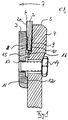
- a blow bar arrangement is shown a blow bar 2 on, with a mounting plate 3 on the vane 4 of a racquet wheel a cutting machine is attached.
- the blow bar 2 has an over the radially outer end of the fifth the racket wheel protruding wear edge 6, the upon rotation of the racket wheel 4 in the direction of arrow 7 a chip knife (not shown) with a Zerspanspalt predetermined gap width forms.
- the front in the direction of rotation Side 2a of the blow bar points at its from the wear edge 6 remote, radially inner region over a the complete blow bar width extending profiling 8 on, whose profile centers a distance of about 3.5mm to each other have, wherein the single profile has a width of about 1.5mm owns.
- On the rear side 9 in the direction of rotation the blow bar plan on a support surface 10 of the vane on.
- the mounting plate 3 has a bearing surface 11, with which they on a radially inner bearing surface 12th the vane 4 rests. Radially outside the support surface 11 is in the mounting plate 3 is a threaded blind bore 13 is provided, in which a through the vane 4 of the racquet wheel kicking bolt 14 firmly screwed into it is. Radially above the threaded bore 13, the Attachment plate 3, a nose 15 which in a groove 16 enters, which is a well-defined distance to the racket center has. Radially out of the neck 15 is the profiling 8 provided.
- the mounting plate 3 in attached by finger 15 and groove 16 predetermined position.
- the bolts 14 are not tightened at this time, so that a new blow bar 2 in the position shown can be easily inserted axially. This occurs the profile 8 on the blow bar with the counter profile 9 of Mounting plate engages and meshes with this.
- blow bar 20 is a blow bar 20 on a blow bar holder 21 fixed by a bolt 22.
- the blow bar holder 22 has at its radially inner end a Nose 23, in the usual way in a groove 24 of the racquet wheel 25 occurs and wherein the blow bar holder 21st by means of a clamping device 26a, 26b to the Schlagancenrad non-positive and, as far as form-fitting by nose and groove 23 and 24 is provided, is mounted in a form-fitting manner.
- the bolt 22 now passes through a slot 27 (Fig.2a), which in the blow bar holder 21 as shown at 28a, 28b is formed graduated.
- the upper wide step 28a for receiving the screw head 22a is by superposition designed by a plurality of circular holes such that webs 29 protrude into the slot inside, so that the bolt head 22a are only positioned at predetermined fixed locations can.
- the various, the upper step 28a of the slot 28 forming individual holes are spaced by 3-4mm each.
- gauges can be attached to the machine to the insertion of the blow bars in exactly the right radial Ensure safe distance.
- the profiling can also be in the racquet wheel be provided.
- blow bar could be with both sides be profiled.
- blow bar could only have one Nose be provided, which optionally in one of several Grooves occurs in the mounting plate and / or the vane are provided.
- a nose can look be worked out the full material or by a Insert, e.g. a square bar inserted in a groove will be realized.
- the invention is also in Zerspanmaschinen various crushers with rotating Rotor bodies can be used for soft material, where a wear body like a blow bar especially for gap size adjustment must be readjusted.
- Other machines, which crush soft within the meaning of the invention, are e.g. Dual power mills.
Description
- Fig. 1
- eine Schlagleistenbefestigung gemäß der vorliegenden Erfindung;
- Fig. 2
- eine weitere Schlagleistenbefestigung gemäß der vorliegenden Erfindung;
- Fig. 2a
- ein Detail von Fig. 2.
Claims (14)
- Schlagleiste (2) für einen Weichmaterialzerkleinerungsmaschinenrotor, insbesondere ein Zerspanmaschinenschlägerrad (4) mit
einem Fixiermittel zur Fixierung an einer zum Schlägerrad festen Schlagleistenhalterung und
einem Kompensationsmittel zur allgemeinen radialen Positionsveränderung auf Schlagleistenverschleiß hin,
dadurch gekennzeichnet, daß
das Kompensationsmittel (8, 9) als Stufenkompensationsmittel zum allgemeinen formschlüssigen Eingriff mit einer auf der Halterung vorgesehenen Komplementärstruktur in einer mehrerer wahlweise einnehmbarer Radialstufen ausgebildet ist und
das Fixiermittel eine von dem Stufenkompensationsmittel räumlich getrennte Kraftschlußfläche umfaßt, über welche von der Schlagleiste zur Schlagleistenhalterung (1) ein Kraftschluß hergestellt werden kann, um die im Betrieb auf die Schlagleiste einwirkenden Kräfte zueinander weitgehend aufzunehmen. - Schlagleiste nach Anspruch 1, worin bezüglich der Rotor-Drehrichtung das Stufenkompensationsmittel auf einer Seite und die Kraftschlußfläche auf der gegenüberliegenden Seite angebracht ist.
- Schlagleiste nach einem der vorhergehenden Ansprüche, worin das Kompensationsmittel durch eine an der Schlagleiste vorgesehene Profilierung gebildet ist, die zwecks stufenweiser Verschleißkompensation zum Eingriff mit einer Gegenprofilierung in der Schlagleistenhalterung ausgebildet ist.
- Schlagleiste nach dem vorhergehenden Anspruch, worin die der profilierten Seite gegenüberliegende Seite plan ist, um so eine Auflagefläche für eine wenigstens auch kraftschlüssige Fixierung in der Halterung bilden.
- Schlagleiste nach einem der vorhergehenden Ansprüche, worin die Profilierung auf der Schlagleiste asymmetrisch angeordnet ist und vorzugsweise die Schlagleiste nur eine bestimmungsgemäße Verschleißkante aufweist.
- Schlagleiste nach dem vorhergehenden Anspruch, worin die asymmetrisch angeordnete Profilierung entfernt von der Verschleißkante liegt.
- Schlagleiste nach dem vorhergehenden Anspruch mit einer durch Fräsen, Drehen und/oder Schleifen aus der Verschleißplatte genommenen Profilierung.
- Schlagleiste nach einem der vorhergehenden Ansprüche, worin die Profilierung durch eine Vielzahl von sich parallel zueinander und vorzugsweise zugleich zur Verschleißkante erstreckender Vertiefungen gebildet ist.
- Schlagleiste nach dem vorhergehenden Anspruch, worin die Vertiefungen einen Abstand von 3mm bis 4mm aufweisen.
- Befestigungsplatte (3) für eine Schlagleiste (2) nach einem der vorhergehenden Ansprüche mit
einem Haltemittel (15) zum Halten der Befestigungsplatte (3) am Schlägerrad (4) einer Zerspanmaschine mit exakt definiertem Radialabstand,
einem Fixiermittel (13, 14) zum Fixieren der Schlagleiste (2) am Schlägerrad (4) und
einem Kompensationsmittel (9) zur allgemeinen radialen Positionsveränderung auf Schlagleistenverschluß hin, dadurch gekennzeichnet, daß
das Kompensationsmittel als Stufenkompensationsmittel (9) zum allgemeinen formschlüssigen Eingriff mit einer zwischen Schlagleiste (2) und Befestigungsplatte (3) komplementären Struktur in einer mehrerer wahlweise einnehmbarer Radialstufen ausgebildet ist und das Fixiermittel (13, 14) eine von dem Stufenkompensationsmittel räumlich getrennte Kraftschlußfläche umfaßt, über welche von der Schlagleiste (2) zur Befestigungsplatte (3) ein Kraftschluß hergestellt werden kann, um die im Betrieb auf die Schlagleiste (2) einwirkenden Kräfte zueinander weitgehend aufzunehmen. - Befestigungsplatte (3) nach dem vorhergehenden Anspruch, dadurch gekennzeichnet, daß
das Fixiermittel (15) zum Fixieren der Befestigungsplatte (3) am Schlägerrad durch Festschrauben ausgebildet ist und das Haltemittel (13) eine Fläche zum kraftschlüssigen Klemmen der Schlagleiste (2) gegen das Schlägerrad (4) umfaßt. - Befestigungsplatte (21) nach einem der vorhergehenden Ansprüche, worin das Fixiermittel einen Bolzen (22) und/oder eine Schraube umfaßt, mit welchem die Schlagleiste (20) an die Befestigungsplatte (21) fest kraftschlüssig angezogen werden kann.
- Befestigungsplatte (21) nach dem vorhergehenden Anspruch, worin das Kompensationsmittel als in Radialrichtung langgestrecktes Durchgangsloch (27) ausgebildet ist, in welchem der Bolzen (22) zur stufenweisen Verschleißkompensation nur in vorgegebenen festen Positionen angezogen werden kann.
- Weichmaterialzerkleinerungsmaschinenrotor, insbesondere ein Zerspanmaschinenschlägerrad mit wenigstens einer Schlagleiste (2, 20) und/oder Befestigungsplatte (3, 21) nach einem der vorhergehenden Ansprüche.
Applications Claiming Priority (2)
| Application Number | Priority Date | Filing Date | Title |
|---|---|---|---|
| DE1998147798 DE19847798A1 (de) | 1998-10-16 | 1998-10-16 | Schlagleistenhalterung |
| DE19847798 | 1998-10-16 |
Publications (2)
| Publication Number | Publication Date |
|---|---|
| EP0993920A1 EP0993920A1 (de) | 2000-04-19 |
| EP0993920B1 true EP0993920B1 (de) | 2005-11-09 |
Family
ID=7884723
Family Applications (1)
| Application Number | Title | Priority Date | Filing Date |
|---|---|---|---|
| EP19990116379 Expired - Lifetime EP0993920B1 (de) | 1998-10-16 | 1999-08-20 | Schlagleistenhalterung |
Country Status (2)
| Country | Link |
|---|---|
| EP (1) | EP0993920B1 (de) |
| DE (2) | DE19847798A1 (de) |
Cited By (3)
| Publication number | Priority date | Publication date | Assignee | Title |
|---|---|---|---|---|
| DE102010036650A1 (de) | 2010-07-27 | 2012-02-02 | Siempelkamp Maschinen- Und Anlagenbau Gmbh & Co. Kg | Leitschaufel für eine Zerspannungsvorrichtung |
| CN102773899A (zh) * | 2012-07-17 | 2012-11-14 | 江苏大唐机械有限公司 | 环式刨片机叶片夹紧结构 |
| CN103465327A (zh) * | 2013-09-27 | 2013-12-25 | 金华市捷特包装有限公司 | 用于环式刨片机的刀环装置以及环式刨片机 |
Family Cites Families (5)
| Publication number | Priority date | Publication date | Assignee | Title |
|---|---|---|---|---|
| DE7306038U (de) * | 1973-02-17 | 1973-05-30 | Hazemag A Kg | Schlagleiste fuer prallmuehlenrotoren |
| DE2616849A1 (de) * | 1976-04-15 | 1977-11-03 | Pallmann Kg Maschf | Verschleissplatte fuer zerspaner |
| DE3334783A1 (de) * | 1982-09-28 | 1984-03-29 | Pallmann Maschinenfabrik GmbH & Co KG, 6660 Zweibrücken | Halterung fuer nachstellbare schlagplatten an schlaegerrotoren von zerkleinerungsmaschinen |
| DE19506817A1 (de) * | 1995-02-27 | 1996-08-29 | Jackering Altenburger Masch | Schleuderteller für eine Mühle |
| DE19619338B4 (de) * | 1996-05-14 | 2007-03-01 | B. Maier Zerkleinerungstechnik Gmbh | Zerspaner für Hackschnitzel |
-
1998
- 1998-10-16 DE DE1998147798 patent/DE19847798A1/de active Pending
-
1999
- 1999-08-20 EP EP19990116379 patent/EP0993920B1/de not_active Expired - Lifetime
- 1999-08-20 DE DE59912759T patent/DE59912759D1/de not_active Expired - Lifetime
Cited By (7)
| Publication number | Priority date | Publication date | Assignee | Title |
|---|---|---|---|---|
| DE102010036650A1 (de) | 2010-07-27 | 2012-02-02 | Siempelkamp Maschinen- Und Anlagenbau Gmbh & Co. Kg | Leitschaufel für eine Zerspannungsvorrichtung |
| WO2012013653A1 (de) | 2010-07-27 | 2012-02-02 | Siempelkamp Maschinen- Und Anlagenbau Gmbh & Co. Kg | Leitschaufel für eine zerkleinerungsvorrichtung |
| CN102985183A (zh) * | 2010-07-27 | 2013-03-20 | 西姆佩尔坎普机械设备制造有限责任公司和两合公司 | 用于破碎装置的导叶 |
| CN102985183B (zh) * | 2010-07-27 | 2014-10-15 | 西姆佩尔坎普机械设备制造有限责任公司和两合公司 | 用于破碎装置的导叶 |
| CN102773899A (zh) * | 2012-07-17 | 2012-11-14 | 江苏大唐机械有限公司 | 环式刨片机叶片夹紧结构 |
| CN103465327A (zh) * | 2013-09-27 | 2013-12-25 | 金华市捷特包装有限公司 | 用于环式刨片机的刀环装置以及环式刨片机 |
| CN103465327B (zh) * | 2013-09-27 | 2016-08-24 | 金华市捷特包装有限公司 | 用于环式刨片机的刀环装置以及环式刨片机 |
Also Published As
| Publication number | Publication date |
|---|---|
| DE19847798A1 (de) | 2000-04-20 |
| EP0993920A1 (de) | 2000-04-19 |
| DE59912759D1 (de) | 2005-12-15 |
Similar Documents
| Publication | Publication Date | Title |
|---|---|---|
| EP0085176B1 (de) | Messerkopf für Verzahnungsmaschinen | |
| EP1588786A1 (de) | Häckselmesser sowie Gegenmesser für eine Häckselvorrichtung und Verfahren seiner Herstellung | |
| EP0090248A2 (de) | Vorrichtung zum Zerkleinern von Dokumentmaterial | |
| EP2598247B1 (de) | Leitschaufel für eine zerkleinerungsvorrichtung | |
| EP3202290A1 (de) | Mahlwerk, mühle, kaffeezubereitungsvorrichtung mit mühle sowie mahlverfahren | |
| DE102008005941A1 (de) | Zerkleinerungsvorrichtung für Aufgabengut mit gegenläufigen Rotoren | |
| DE10323769B3 (de) | Zerkleinerungsvorrichtung mit einstellbarem Schnittwinkel | |
| EP2374544B1 (de) | Vorrichtung zum Zerkleinern von kompostierbarem Material | |
| EP0993920B1 (de) | Schlagleistenhalterung | |
| WO2000047065A1 (de) | Vorrichtung zur zerkleinerung von organischen substanzen | |
| DE102015005787B4 (de) | Zerkleinerungseinheit für eine Zerkleinerungsvorrichtung zum Zerkleinern von Aufgabegut, insbesondere Messerkorb | |
| EP1927444B1 (de) | Hobelmesser | |
| DE10143184A1 (de) | Vorrichtung zum Zerkleinern von Aufgabegut sowie Messerhalteplatte | |
| EP0122402A2 (de) | Schrotmühle | |
| DE3334783A1 (de) | Halterung fuer nachstellbare schlagplatten an schlaegerrotoren von zerkleinerungsmaschinen | |
| DE2221479A1 (de) | Messerwalze fuer zerspanungsmaschinen | |
| DE4443275C2 (de) | Hackmesser mit Stabilisierungskanten zum Einsatz in Zerkleinerungsvorrichtungen | |
| DE2454476C3 (de) | Einzugsbalken für Schneidmühlen | |
| DE2618254A1 (de) | Messertrommel, insbesondere fuer hackmaschinen zur zerkleinerung von hoelzern und abfaellen | |
| DE102013217164A1 (de) | Zerkleinerungsvorrichtung | |
| DE2811376A1 (de) | Rotir fuer prallmuehlen, insbesondere fuer sandprallmuehlen | |
| DE102011105321A1 (de) | Trommelschneidemaschine und Messerkorb für eine solche Maschine | |
| DE19947399C2 (de) | Messerträger für eine Zerspanervorrichtung | |
| DE2037241B2 (de) | Fraeser | |
| DE2037241C (de) | Fräser |
Legal Events
| Date | Code | Title | Description |
|---|---|---|---|
| PUAI | Public reference made under article 153(3) epc to a published international application that has entered the european phase |
Free format text: ORIGINAL CODE: 0009012 |
|
| AK | Designated contracting states |
Kind code of ref document: A1 Designated state(s): DE IT |
|
| AX | Request for extension of the european patent |
Free format text: AL;LT;LV;MK;RO;SI |
|
| 17P | Request for examination filed |
Effective date: 20001019 |
|
| AKX | Designation fees paid |
Free format text: AT BE CH CY DE DK ES FI FR GB GR IE IT LI LU MC NL PT SE |
|
| AXX | Extension fees paid |
Free format text: AL PAYMENT 20001019;LT PAYMENT 20001019;LV PAYMENT 20001019;MK PAYMENT 20001019;RO PAYMENT 20001019;SI PAYMENT 20001019 |
|
| RBV | Designated contracting states (corrected) |
Designated state(s): DE IT |
|
| DAX | Request for extension of the european patent (deleted) | ||
| GRAP | Despatch of communication of intention to grant a patent |
Free format text: ORIGINAL CODE: EPIDOSNIGR1 |
|
| GRAS | Grant fee paid |
Free format text: ORIGINAL CODE: EPIDOSNIGR3 |
|
| RAP1 | Party data changed (applicant data changed or rights of an application transferred) |
Owner name: STEINMETZ INNOVATION GMBH |
|
| GRAA | (expected) grant |
Free format text: ORIGINAL CODE: 0009210 |
|
| AK | Designated contracting states |
Kind code of ref document: B1 Designated state(s): DE IT |
|
| REF | Corresponds to: |
Ref document number: 59912759 Country of ref document: DE Date of ref document: 20051215 Kind code of ref document: P |
|
| PLBE | No opposition filed within time limit |
Free format text: ORIGINAL CODE: 0009261 |
|
| STAA | Information on the status of an ep patent application or granted ep patent |
Free format text: STATUS: NO OPPOSITION FILED WITHIN TIME LIMIT |
|
| 26N | No opposition filed |
Effective date: 20060810 |
|
| PGFP | Annual fee paid to national office [announced via postgrant information from national office to epo] |
Ref country code: DE Payment date: 20110715 Year of fee payment: 13 |
|
| PGFP | Annual fee paid to national office [announced via postgrant information from national office to epo] |
Ref country code: IT Payment date: 20110825 Year of fee payment: 13 |
|
| PG25 | Lapsed in a contracting state [announced via postgrant information from national office to epo] |
Ref country code: IT Free format text: LAPSE BECAUSE OF NON-PAYMENT OF DUE FEES Effective date: 20120820 |
|
| PG25 | Lapsed in a contracting state [announced via postgrant information from national office to epo] |
Ref country code: DE Free format text: LAPSE BECAUSE OF NON-PAYMENT OF DUE FEES Effective date: 20130301 |
|
| REG | Reference to a national code |
Ref country code: DE Ref legal event code: R119 Ref document number: 59912759 Country of ref document: DE Effective date: 20130301 |