EP0991017A2 - Circuit de dètection de mouvement et circuit de suppression de bruit le comprenant - Google Patents
Circuit de dètection de mouvement et circuit de suppression de bruit le comprenant Download PDFInfo
- Publication number
- EP0991017A2 EP0991017A2 EP99119276A EP99119276A EP0991017A2 EP 0991017 A2 EP0991017 A2 EP 0991017A2 EP 99119276 A EP99119276 A EP 99119276A EP 99119276 A EP99119276 A EP 99119276A EP 0991017 A2 EP0991017 A2 EP 0991017A2
- Authority
- EP
- European Patent Office
- Prior art keywords
- signal
- motion
- video signal
- target pixel
- detection circuit
- Prior art date
- Legal status (The legal status is an assumption and is not a legal conclusion. Google has not performed a legal analysis and makes no representation as to the accuracy of the status listed.)
- Withdrawn
Links
Images


Classifications
-
- G—PHYSICS
- G06—COMPUTING; CALCULATING OR COUNTING
- G06T—IMAGE DATA PROCESSING OR GENERATION, IN GENERAL
- G06T7/00—Image analysis
- G06T7/20—Analysis of motion
- G06T7/254—Analysis of motion involving subtraction of images
Definitions
- This invention relates to a motion detection circuit for detecting motion in a video signal and a noise suppression circuit including the motion detection circuit.
- a motion detection circuit for detecting motion in a video signal from a difference signal between the video signal and the one-frame delayed video signal is known and a noise suppression circuit is also known.
- the noise suppression circuit includes the motion detection circuit, a circulation signal generation circuit for generating a circulation signal in accordance with the difference signal and the motion detection signal, and a subtractor for subtracting the circulation signal from the video signal to output a noise suppressed video signal.
- Such a prior art motion detection circuit and a prior art noise suppression circuit are disclosed in Japanese patent application provisional publication No. 9-81754.
- Fig. 8 is a block diagram of such a prior art noise suppression circuit including a prior art motion detection circuit.
- the prior art motion detection circuit includes a frame memory 610 for generating a delayed video signal from the noise suppressed video signal, a subtractor 602 for generating a difference signal (interframe difference signal) between the video signal Vi and the delayed video signal, a motion detection circuit 603 for detecting a motion from the video signal Vi and the delayed video signal to output a motion detection signal.
- the noise suppression circuit further includes a subtractor 607 for generating the difference signal between the video signal Vi and the delayed video signal, a circulation amount determining circuit 608 for generating a circulation signal from the difference signal in accordance with the motion detection signal, and a subtractor 609 for obtaining the difference between the video signal Vi and the circulation signal to output the noise suppressed video signal.
- the aim of the present invention is to provide a superior motion detection circuit and a superior noise suppression circuit.
- a first motion detection circuit including: a delay for generating a delayed video signal from a video signal, the delayed video signal being delayed by one frame from the video signal; an interframe difference signal generation circuit for generating an interframe difference signal between the video signal and the delayed video signal; an edge detection signal generation circuit for detecting an edge from the video signal and the delayed video signal and generating an edge detection signal; and a motion judging circuit for judging a motion in the video signal at a target pixel from the interframe difference signal in accordance with the edge detection signal to output a motion detection signal, wherein the motion Judging circuit includes: a peripheral pixel comparing circuit for detecting polarities of the interframe difference signal at each pixel at a predetermined area around the target pixel, detecting a difference in the number between the positive and negative polarities of the interframe difference signal at each pixel at the predetermined area and an absolute value of the difference, obtaining a J-valued first result from the absolute value; and a majority detection circuit including a memory
- the first motion detection circuit may further include a low-pass filter for low-pass-filtering the interframe difference signal; and a selector for supplying either of an output of the low-pass filter or the interframe difference signal to the motion judging circuit as the interframe difference signal in accordance with a selection signal.
- the motion judging circuit mentioned in the first motion detection circuit may further include a polarity deviation detecting circuit for detecting polarities of the interframe difference signal at each pixel of the video signal, detecting agreement of the polarities of all pixels at any of an upper left area of the target pixel, an upper right area of the target pixel, a lower left area of the target pixel, and a lower right area of the target pixel, and judging motion in the interframe difference signal at the target pixel to be moving in the presence of the agreement, each of the upper left area, the upper right area, the lower left area, and the lower right area including M x N pixels of the video signal, M and N being natural numbers, wherein the polarity deviation detection circuit changes the second result from the intermediate movement to the stopping in accordance with the agreement to output the motion detection signal when the second result is indicative of the intermediate motion and outputs the motion detection signal with the second result unchanged when the second result is indicative of the moving and stopping.
- a polarity deviation detecting circuit for detecting polarities of the interframe
- the upper left area, the upper right area, the lower left area, and the lower right area include the target pixel or are outside and adjacent to the target pixel.
- the edge detection signal generation circuit mentioned in the first motion detection circuit may include a first edge detection circuit for detecting an edge from the video signal, a second edge detection circuit for detecting an edge from the delayed video signal, a third edge detection circuit for detecting an edge from the video signal and the delayed video signal, and a switch responsive to a selection signal for outputting either of an output of the first, second, or third edge detection circuit as the edge detection signal.
- the edge detection signal generation circuit may be further responsive to a width control signal indicative of values of m and n and the edge detection signal generation circuit may detect the edge detection signal with a horizontal width of (2m + 1) pixels and with a vertical width of (2n + 1) pixels, the n and m are positive integers.
- values of the M and N may be controlled in accordance with the edge detection signal.
- a noise suppression apparatus including: a motion detection circuit including: a delay for generating a delayed video signal from a video signal, the delayed video signal being delayed by one frame from the video signal; an interframe difference signal generation circuit for generating an interframe difference signal between the video signal and the delayed video signal; a low-pass filter for low-pass-filtering the interframe difference signal; a switch for outputting either of an output of the low-pass filter or the interframe difference signal in accordance with a selection signal; an edge detection signal generation circuit for detecting an edge from the video signal and the delayed video signal and generating an edge detection signal; and a motion judging circuit for judging motion in a target pixel of the video signal from an output of the switch in accordance with the edge detection signal; a circulation signal generation circuit for generating a circulation signal in accordance with the interframe difference signal and the judged motion; and a difference signal generation circuit for generating a difference signal between the circulation signal and the video signal to output a noise suppressed video signal, where
- the circulation signal generation circuit may include: a coefficient generation circuit for generating a coefficient k, k ⁇ 0 ⁇ 1 in accordance with a judging result of the motion judging circuit; and a multiplier for multiplying the video signal by the coefficient k to output a circulation signal
- the coefficient k when the motion judging circuit judges the motion to be stopping is greater than the coefficient k when the motion judging circuit judges the motion to be moving.
- the motion detection circuit in the noise suppression apparatus may be replaced with each of the motion detection circuit mentioned above.
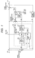
- Fig. 1 is a block diagram of the embodiment of the present invention showing a structure of a motion detection circuit and a noise suppression circuit including the motion detection circuit.
- a motion detection circuit of the embodiment includes a frame memory 111 (delay) for generating a delayed video signal (one-frame-delayed video signal) Vf from a video signal Vi, a subtractor 102 for generating a difference signal between the video signal Vi and the delayed video signal Vf as an interframe difference signal Sd, and a motion detection signal generation circuit 103 for detecting a motion in the interframe difference signal Sd at a target pixel to output a motion detection signal Sm.
- a frame memory 111 delay
- Vf delayed video signal
- a subtractor 102 for generating a difference signal between the video signal Vi and the delayed video signal Vf as an interframe difference signal Sd
- a motion detection signal generation circuit 103 for detecting a motion in the interframe difference signal Sd at a target pixel to output a motion detection signal Sm.
- the noise suppression circuit includes a subtractor 108 for generating the interframe difference signal Sd from the video signal Vi and the delayed video signal Vf, a circulation signal generation circuit 109 for generating a circulation signal 109a from the interframe difference signal in accordance with the motion detection signal Sm, and a subtractor 110 for obtaining a difference between the video signal Vi and the circulation signal 109a to output a noise suppressed video signal Vo.
- the circulation signal generation circuit 109 includes: a coefficient generation circuit 113 for generating a coefficient k, k ⁇ 0 ⁇ 1, in accordance with the motion detection signal Sm from the motion judging circuit 107 and a multiplier 114 for multiplying the video signal by the coefficient k.
- Either of the subtractors 102 and 108 can be omitted.
- An input of the frame memory 111 is supplied with the video signal Vi instead the noise suppressed video signal Vo if only motion detection circuit is used.
- the video signal Vi inputted at a video signal input terminal 101 is supplied to the subtractor 102, a subtractor 108, and to the subtractor 110.
- the subtractor 110 subtracts the circulation signal 109a from the video signal Vi to generate the noise suppressed video signal Vo which is an output of the noise suppressing circuit.
- the noise suppressed video signal Vo is supplied to the frame memory 111 to delay the video signal Vi by one frame to output the delayed video signal Vf.
- the subtractor 102 subtracts the delayed video signal Vf from the video signal Vi to generate the interframe difference signal Sd which is supplied to the low-pass filter 104 and to the selector 105 of the motion detection signal generation circuit 103.
- the interframe difference signal Sd is low-pass-filtered by the low-pass filter 104.
- the selector 105 selects either the interframe difference signal Sd or the output of the low-pass filter 104 in accordance with the selection signal 112. That is, switching the selector 105 is effected in accordance with the frequency characteristic of the interframe difference signal Sd supplied to the motion detection signal generation circuit 103 to supply the interframe difference signal having an optimum frequency characteristic for a motion judging circuit 107 mentioned later.
- the motion detection signal generation circuit 103 further includes an edge detection circuit 106 for detecting an edge from the video signal Vi and the delayed video signal Vf and generating an edge detection signal Edgm and the motion judging circuit 107 for judging a motion in the interframe difference signal at a target pixel from an output of the selector 105 in accordance with the edge detection signal Edgm to output the motion detection signal Sm.
- the edge detection circuit 106 detects an edge portion of the object from the video signal Vi and the delayed video signal Vf to generate the edge detection signal Edgm for the polarity deviation detection circuit 203.
- the motion judging circuit 107 judges the degree of motion at a target pixel TP and the result is supplied to the circulation signal generation circuit 109.
- the subtractor 108 generates the interframe difference signal Sd which is supplied to a coefficient generation circuit 113 of the circulation signal generation circuit 109 which determines the coefficient K as follows:
- K k1 . 0 ⁇ k3 ⁇ k2 ⁇ k1 ⁇ 1.
- the interframe difference signal Sd is multiplied by the coefficient K with the multiplier 114 to generate the circulation signal 109a which is supplied to the subtractor 110.
- the subtractor 110 subtracts the circulation signal 109a from the video signal Vi to generate the noise suppressed video signal Vo as mentioned above.
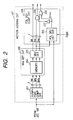
- Fig. 2 is a block diagram of this embodiment showing the structure of the motion judging circuit 107 shown in Fig. 1.
- the motion judging circuit 107 includes a peripheral pixel comparing circuit 201, a majority detection circuit 202, and a polarity deviation compensation circuit 206.
- Fig. 3 is an illustration of the embodiment for illustrating an operation of the peripheral pixel comparing circuit 201.
- the peripheral pixel comparing circuit 201 detects polarities of the interframe difference signal Sd at each pixel at a predetermined area around a target pixel as shown in Fig. 3, for example 5 x 3 including the target pixel TP, detects the number of positive polarities PP of the interframe difference signal Sd at the predetermined area and the number of negative polarities NP of the interframe difference signal at the predetermined area, obtains a difference (PP - NP) in the number between the positive and negative polarities and an absolute value of the difference
- J-1 different references i.e., TH _ S and TH _ M
- the video signal at the target pixel is judged to be moving (Smo).
- J-valued (three-valued) first judging result is supplied to the majority detection circuit 202 which effects motion judgment again in response to the judging result of the intermediate motion Smi.
- J is a natural number more than one.
- the first judging result from the peripheral pixel comparing circuit 201 is supplied to the majority detecting circuit 202 to provide further motion judgement to provide further accurate motion judgement.
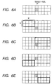
- Fig. 4 is an illustration of this embodiment showing operation of the majority detection circuit 202.
- the majority detection circuit 202 includes a memory 204 for storing the first judging results of the peripheral pixel comparing circuit 201 and reads and outputs the first judging result at a predetermined peripheral area including Q pixels as shown in Fig. 4, for example, eight pixels around the target pixel TP, and a majority detector 205.
- the majority detector 205 detects a majority of the Q results of the peripheral pixel comparing circuit 201 at Q pixels around the target pixel TP.
- the majority detector 205 detects majority of eight first judging results and if more than R1 pixels show the same judging result, the majority detector 205 detects the majority as the second judging result to equalize the motion judgment at the target pixel TP to the judging results at adjacent pixels around the target pixel TP to avoid an isolated judging result. More specifically, if the motion at four pixels out of the eight adjacent pixels are judged to be moving and motion at another four adjacent pixels are judged to be intermediate motion, the second judging result is made to be the intermediate motion. If the motion at four adjacent pixels is judged to be intermediate motion and motion at another four pixels is judged to be stopping, the second judging result of the target pixel is judged as stopping to provide the second judging result which is weighted to the side of stopping. That is, the intermediate motion judged by the peripheral pixel comparing circuit 201 is judged again to stopping, so that noise at the image which is stopping is reduced.
- Figs. 5A to 5E and Figs. 6A to 6E are illustrations of areas of pixels to be processed by the polarity deviation detection circuit 203.
- the upper left area UL shown in Fig. 5B, the upper right area UR shown in Fig. 5C, the lower left area LL shown in Fig. 5D, and the lower right area LR shown in Fig. 5E include the target pixel shown in Fig. 5A.
- the upper left area shown in Fig. 6B, the upper right area shown in Fig. 6C. the lower left area shown in Fig. 6D, and the lower right area shown in Fig. 6E outside the target pixel TP shown in Fig. 6A but adjacent to the target pixel TP.
- the polarity deviation compensation circuit 206 includes a polarity deviation detection circuit 203 and an inverter 207, an AND gate 208, and an OR gate 209.
- the polarity deviation detection circuit 203 detects polarities of the differential signal Sd at each pixel of the video signal, detects agreement of the polarities of all pixels at any of an upper left area UL of the target pixel, an upper right area UR of the target pixel, a lower left area LL of the target pixel, and a lower right area LR of the target pixel, and judges the motion in the interframe difference signal Sd at the target pixel TP as moving in the presence of the agreement.
- the polarity deviation compensation circuit 206 compensates the second judging result of the majority detection circuit 202 from the intermediate motion (Smi) with the inverter 207 and the AND gate 208.
- the OR gate 209 does not compensate the second judging result of the majority detection circuit 202 in accordance with the result of the polarity deviation detection circuit 203.
- the majority detection circuit 202 judges the motion as intermediate motion and the polarity deviation detection circuit judges the motion to be moving, the majority detection circuit outputs L logic level at a signal Sst, H logic level at a signal Smi (an output of the AND gate 208), and L logic level at a signal Smo (an output of the OR gate 209).
- the polarity deviation detection circuit 203 judges the motion and if the third judging result is stopping, the polarity deviation detection circuit 203 outputs H logic level. Then, the inverter 207 outputs L logic level, so that the H logic level at an output of the AND gate 208 is changed to L logic level.
- L logic level at an output of the OR gate 209 is unchanged.
- the polarity deviation detection circuit 203 If the third judging result of the polarity deviation detection circuit 202 is not moving, the polarity deviation detection circuit 203 outputs L logic level, so that the AND gate 208 remains H logic level and the output of the OR gate 209 remains L logic level. As mentioned, the motion judgement is effected again, so that a more accurate judgement is provided.
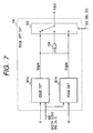
- Fig. 7 is a block diagram of this embodiment showing the structure of the edge detection circuit 106 shown in Fig. 1.
- the edge detection circuit 106 includes a first edge detection circuit 301a, a second edge detection circuit 301b, an OR gate 304, and an edge selection circuit 302.
- the first edge detection circuit 301a detects an edge from the video signal Vi with width of horizontally arranged (2m + 1) pixels (the target pixel and m right pixels and m left pixels) and width of vertically arranged (2n + 1) pixels (the target pixel and n upper pixels and n lower pixels) to generate the edge detection signal Edgmi.
- the second edge detection circuit 301b detects an edge from the video signal Vf with width of horizontally arranged (2m + 1) pixels and width of vertically arranged (2n + 1) pixels to generate the edge detection signal Edgmf.
- the OR gate 304 generates an edge detection signal which is intermediate between the edge detection signals Edgmi and Edgmf.
- the edge selection circuit 302 outputs either the edge detection signal Edgmi, the edge detection signal Edgmf, or the output of the OR gate 304 as the edge detection signal Edgm in accordance with the selection signal 303.
- the edge detection signal Edgm represents an edge with H logic level (1) and a flat portion with L logic level (0).
- the polarity detection circuit 203 controls the size (M, N) of the upper left area UL, the upper right area UR, the lower left area LL, and the lower right area LR in accordance with the edge detection signal Edgm. More specifically, when the edge detection signal is H (1), the number of the pixels (M, N) at the area is reduced, for example 3 x 2 pixels and if the edge detection signal is L (0), the number of pixels (M x N) is made large, for example 5 x 2 pixels, so that generation of after image is suppressed and noise at stopping areas is reduced.
- the motion detection is effected more accurately, so that after image by movement of image is suppressed and the noise at stopping portions are suppressed.
- a motion detection circuit In a motion detection circuit, a difference signal between the video and one-frame delayed video signals is generated. An Edge signal is generated from the video and delayed video signals. Motion in a target pixel is judged from the interframe difference signal according to the edge signal.
- a motion judging circuit further includes an LPF and a selector for supplying an output of the LPF or the difference signal.
- the motion judging circuit may further includes: a peripheral pixel comparing circuit (may be bypassed) for detecting motion at the pixel by checking polarities of the difference signal at an area around the target pixel; a majority detection circuit (may be bypassed) for detecting a majority of the results of the polarity deviation detection circuit to judge the motion with deviation to a side of stopping; and a polarity deviation detecting circuit for judging the motion as moving in the presence of agreement of the polarities of all pixels at any of peripheral areas around the target pixel.
- the size of the peripheral areas are controlled.
- the polarity deviation circuit may compensate the result of the majority detection circuit. Width of the edge signal is controlled.
- a noise suppression apparatus including a motion detection circuit mentioned above is also disclosed.
Applications Claiming Priority (2)
| Application Number | Priority Date | Filing Date | Title |
|---|---|---|---|
| JP27625498A JP3314043B2 (ja) | 1998-09-29 | 1998-09-29 | 動き検出回路とノイズ低減装置 |
| JP27625498 | 1998-09-29 |
Publications (2)
| Publication Number | Publication Date |
|---|---|
| EP0991017A2 true EP0991017A2 (fr) | 2000-04-05 |
| EP0991017A3 EP0991017A3 (fr) | 2000-10-25 |
Family
ID=17566872
Family Applications (1)
| Application Number | Title | Priority Date | Filing Date |
|---|---|---|---|
| EP99119276A Withdrawn EP0991017A3 (fr) | 1998-09-29 | 1999-09-28 | Circuit de dètection de mouvement et circuit de suppression de bruit le comprenant |
Country Status (4)
| Country | Link |
|---|---|
| US (1) | US6567468B1 (fr) |
| EP (1) | EP0991017A3 (fr) |
| JP (1) | JP3314043B2 (fr) |
| CN (1) | CN1155225C (fr) |
Families Citing this family (13)
| Publication number | Priority date | Publication date | Assignee | Title |
|---|---|---|---|---|
| JP3737436B2 (ja) * | 2002-01-24 | 2006-01-18 | 株式会社メガチップス | ノイズ除去方法およびノイズ除去装置 |
| EP1526740A1 (fr) * | 2003-10-21 | 2005-04-27 | Deutsche Thomson-Brandt Gmbh | Procédé et dispositif pour la réduction de bruit des signaux de chrominance en façon temporellement recursif |
| JP4280614B2 (ja) * | 2003-12-09 | 2009-06-17 | Okiセミコンダクタ株式会社 | ノイズ低減回路及び方法 |
| US7924345B2 (en) * | 2005-10-20 | 2011-04-12 | Broadcom Corp. | Method and system for deinterlacing using polarity change count |
| US7791673B2 (en) * | 2005-10-20 | 2010-09-07 | Broadcom Corporation | Method and system for polarity change count |
| US7961256B2 (en) * | 2006-10-17 | 2011-06-14 | Broadcom Corporation | System and method for bad weave detection for inverse telecine |
| TWI401944B (zh) * | 2007-06-13 | 2013-07-11 | Novatek Microelectronics Corp | 用於視訊處理系統之雜訊消除裝置 |
| US20090010341A1 (en) * | 2007-07-02 | 2009-01-08 | Feng Pan | Peak signal to noise ratio weighting module, video encoding system and method for use therewith |
| EP2114068A1 (fr) * | 2008-04-30 | 2009-11-04 | Sony Corporation | Procédé de conversion d'une image et unité de conversion d'images |
| JP5417746B2 (ja) * | 2008-06-19 | 2014-02-19 | ソニー株式会社 | 動き適応型ノイズ低減装置、画像信号処理装置、画像入力処理装置、および、動き適応ノイズ低減方法 |
| JP5909126B2 (ja) * | 2012-03-28 | 2016-04-26 | 西日本電信電話株式会社 | 監視システム、及び監視方法 |
| US9019340B2 (en) * | 2012-03-28 | 2015-04-28 | Intel Corporation | Content aware selective adjusting of motion estimation |
| WO2018193704A1 (fr) * | 2017-04-20 | 2018-10-25 | ソニー株式会社 | Système de traitement de signal, dispositif de traitement de signal et procédé de traitement de signal |
Citations (6)
| Publication number | Priority date | Publication date | Assignee | Title |
|---|---|---|---|---|
| EP0310032A2 (fr) * | 1987-10-02 | 1989-04-05 | Nippon Hoso Kyokai | Circuit de détection de mouvement |
| EP0502615A2 (fr) * | 1991-03-07 | 1992-09-09 | Matsushita Electric Industrial Co., Ltd. | Procédé de détection de mouvement dans un signal vidéo et réducteur de bruit avec utilisation de ce procédé |
| JPH07131676A (ja) * | 1993-10-28 | 1995-05-19 | Toshiba Corp | 動き検出回路 |
| US5600737A (en) * | 1991-04-12 | 1997-02-04 | Mitsubishi Denki Kabushiki Kaisha | Motion compensation predicting encoding method and apparatus |
| JPH0981754A (ja) * | 1995-09-19 | 1997-03-28 | Matsushita Electric Ind Co Ltd | 動き検出回路 |
| EP0777388A2 (fr) * | 1995-12-08 | 1997-06-04 | Kabushiki Kaisha Toshiba | Codeur et décodeur vidéo avec réduction de bruit |
Family Cites Families (6)
| Publication number | Priority date | Publication date | Assignee | Title |
|---|---|---|---|---|
| US5539469A (en) * | 1994-12-30 | 1996-07-23 | Daewoo Electronics Co., Ltd. | Apparatus for determining motion vectors through the use of an adaptive median filtering technique |
| US5631706A (en) * | 1995-06-07 | 1997-05-20 | Mitsubishi Consumer Electronics America, Inc. | Converter and method for converting video signals of interlace format to video signals of progressive format |
| KR100209793B1 (ko) * | 1995-10-28 | 1999-07-15 | 전주범 | 특징점 기반 움직임 추정을 이용하여 비디오 신호를 부호화 및 복호화하는 장치 |
| JPH1051755A (ja) * | 1996-05-30 | 1998-02-20 | Fujitsu Ltd | テレビ会議端末の画面表示制御装置 |
| US5936676A (en) * | 1997-08-21 | 1999-08-10 | Miranda Technologies Inc. | Apparatus and method for line interpolating an interlaced video signal |
| US6118488A (en) * | 1998-08-31 | 2000-09-12 | Silicon Integrated Systems Corporation | Method and apparatus for adaptive edge-based scan line interpolation using 1-D pixel array motion detection |
-
1998
- 1998-09-29 JP JP27625498A patent/JP3314043B2/ja not_active Expired - Fee Related
-
1999
- 1999-09-13 US US09/394,684 patent/US6567468B1/en not_active Expired - Fee Related
- 1999-09-28 EP EP99119276A patent/EP0991017A3/fr not_active Withdrawn
- 1999-09-29 CN CNB991210670A patent/CN1155225C/zh not_active Expired - Fee Related
Patent Citations (6)
| Publication number | Priority date | Publication date | Assignee | Title |
|---|---|---|---|---|
| EP0310032A2 (fr) * | 1987-10-02 | 1989-04-05 | Nippon Hoso Kyokai | Circuit de détection de mouvement |
| EP0502615A2 (fr) * | 1991-03-07 | 1992-09-09 | Matsushita Electric Industrial Co., Ltd. | Procédé de détection de mouvement dans un signal vidéo et réducteur de bruit avec utilisation de ce procédé |
| US5600737A (en) * | 1991-04-12 | 1997-02-04 | Mitsubishi Denki Kabushiki Kaisha | Motion compensation predicting encoding method and apparatus |
| JPH07131676A (ja) * | 1993-10-28 | 1995-05-19 | Toshiba Corp | 動き検出回路 |
| JPH0981754A (ja) * | 1995-09-19 | 1997-03-28 | Matsushita Electric Ind Co Ltd | 動き検出回路 |
| EP0777388A2 (fr) * | 1995-12-08 | 1997-06-04 | Kabushiki Kaisha Toshiba | Codeur et décodeur vidéo avec réduction de bruit |
Non-Patent Citations (3)
| Title |
|---|
| NOGAKI S ET AL: "A study on HDTV signal coding with motion adaptive noise reduction" SIGNAL PROCESSING OF HDTV, II. PROCEEDINGS OF THE THIRD INTERNATIONAL WORKSHOP ON HDTV, TURIN, ITALY, 30 AUG.-1 SEPT. 1989, 30 August 1989 (1989-08-30), pages 725-730, XP000215290 1990, Amsterdam, Netherlands, Elsevier, Netherlands ISBN: 0-444-88833-0 * |
| PATENT ABSTRACTS OF JAPAN vol. 1995, no. 08, 29 September 1995 (1995-09-29) & JP 07 131676 A (TOSHIBA CORP), 19 May 1995 (1995-05-19) * |
| PATENT ABSTRACTS OF JAPAN vol. 1997, no. 07, 31 July 1997 (1997-07-31) & JP 09 081754 A (MATSUSHITA ELECTRIC IND CO LTD), 28 March 1997 (1997-03-28) * |
Also Published As
| Publication number | Publication date |
|---|---|
| US6567468B1 (en) | 2003-05-20 |
| CN1250304A (zh) | 2000-04-12 |
| CN1155225C (zh) | 2004-06-23 |
| JP2000115586A (ja) | 2000-04-21 |
| JP3314043B2 (ja) | 2002-08-12 |
| EP0991017A3 (fr) | 2000-10-25 |
Similar Documents
| Publication | Publication Date | Title |
|---|---|---|
| US6567468B1 (en) | Motion detection circuit and a noise suppressing circuit including the same | |
| US6687300B1 (en) | Motion detection circuit and a noise suppressing circuit including the same | |
| US6459734B1 (en) | Motion detection circuit and a noise suppression circuit including the same | |
| EP0496635B1 (fr) | Appareil de détection d'un vecteur de mouvement pour détecter le mouvement d'une image pour en prévenir une perturbation | |
| JP3899129B2 (ja) | ビデオノイズ低減方法 | |
| CN106127693A (zh) | 除雾系统和除雾方法 | |
| JPH05233815A (ja) | 動きベクトル検出装置 | |
| JP2006238440A (ja) | 輝度レベルについての動き値補正を持つグローバル動き適応システム | |
| JPS63157574A (ja) | 雑音低減回路 | |
| JP2000333134A (ja) | 補間フィールド生成回路及びフィールド倍速変換回路 | |
| US6781625B2 (en) | Noise reducing apparatus | |
| US8320631B2 (en) | Movement detection apparatus and movement detection method | |
| JPH0846925A (ja) | 画像信号の動き検出回路 | |
| JPH0981754A (ja) | 動き検出回路 | |
| JP3662514B2 (ja) | 欠損画素検出補正装置、欠損画素検出補正方法、欠損画素検出補正プログラム、および、映像信号処理装置 | |
| US20080211960A1 (en) | Method and related apparatus for image de-interlacing | |
| JP2765272B2 (ja) | 輝度信号の自動黒伸長制御装置 | |
| JP2795061B2 (ja) | 輝度信号の自動全体ガンマ制御装置 | |
| JP2765368B2 (ja) | 輝度信号の自動黒ガンマ制御装置 | |
| JP2506499B2 (ja) | 画像の動きベクトル検出装置及び揺れ補正装置 | |
| JP2773464B2 (ja) | 輝度信号の自動ガンマ制御装置 | |
| JP2707917B2 (ja) | 輝度信号の自動黒伸長制御装置 | |
| JP3040251B2 (ja) | 動き検出回路 | |
| JPH08184409A (ja) | 画像目標検出装置 | |
| JP2707916B2 (ja) | 輝度信号の自動白伸長制御装置 |
Legal Events
| Date | Code | Title | Description |
|---|---|---|---|
| PUAI | Public reference made under article 153(3) epc to a published international application that has entered the european phase |
Free format text: ORIGINAL CODE: 0009012 |
|
| AK | Designated contracting states |
Kind code of ref document: A2 Designated state(s): DE FR GB |
|
| AX | Request for extension of the european patent |
Free format text: AL;LT;LV;MK;RO;SI |
|
| PUAL | Search report despatched |
Free format text: ORIGINAL CODE: 0009013 |
|
| AK | Designated contracting states |
Kind code of ref document: A3 Designated state(s): AT BE CH CY DE DK ES FI FR GB GR IE IT LI LU MC NL PT SE |
|
| AX | Request for extension of the european patent |
Free format text: AL;LT;LV;MK;RO;SI |
|
| RIC1 | Information provided on ipc code assigned before grant |
Free format text: 7H 04N 7/36 A, 7H 04N 7/30 B, 7G 06T 7/20 B |
|
| 17P | Request for examination filed |
Effective date: 20001220 |
|
| AKX | Designation fees paid |
Free format text: DE FR GB |
|
| RAP1 | Party data changed (applicant data changed or rights of an application transferred) |
Owner name: PANASONIC CORPORATION |
|
| STAA | Information on the status of an ep patent application or granted ep patent |
Free format text: STATUS: THE APPLICATION IS DEEMED TO BE WITHDRAWN |
|
| 18D | Application deemed to be withdrawn |
Effective date: 20150401 |