EP0990237B1 - Procede de production d'un conteneur, et conteneur ainsi produit - Google Patents
Procede de production d'un conteneur, et conteneur ainsi produit Download PDFInfo
- Publication number
- EP0990237B1 EP0990237B1 EP98936155A EP98936155A EP0990237B1 EP 0990237 B1 EP0990237 B1 EP 0990237B1 EP 98936155 A EP98936155 A EP 98936155A EP 98936155 A EP98936155 A EP 98936155A EP 0990237 B1 EP0990237 B1 EP 0990237B1
- Authority
- EP
- European Patent Office
- Prior art keywords
- aggregate
- outer tube
- annular gap
- container
- metal
- Prior art date
- Legal status (The legal status is an assumption and is not a legal conclusion. Google has not performed a legal analysis and makes no representation as to the accuracy of the status listed.)
- Expired - Lifetime
Links
Images

Classifications
-
- G—PHYSICS
- G21—NUCLEAR PHYSICS; NUCLEAR ENGINEERING
- G21F—PROTECTION AGAINST X-RADIATION, GAMMA RADIATION, CORPUSCULAR RADIATION OR PARTICLE BOMBARDMENT; TREATING RADIOACTIVELY CONTAMINATED MATERIAL; DECONTAMINATION ARRANGEMENTS THEREFOR
- G21F5/00—Transportable or portable shielded containers
Definitions
- the invention relates to a method for producing a Container for the transport and storage of radioactive radiating material as well as a container with which to radioactive radiating material can be transported and stored can.
- Such containers have so-called in the embodiment "Castor container” was very important in the past obtained. They serve radioactive material, for example spent fuel elements from nuclear reactors, from the power plant to an intermediate or final storage point transport.
- the invention is based on these aspects Task based on a method for producing a corresponding Container or one of the aforementioned Provide sufficient container.
- Radioactive rays include alpha rays, beta rays, Gamma rays and neutron rays.
- Alpha and Beta rays generally have such short ranges that for their shielding low material thicknesses (order of magnitude: a few millimeters) are sufficient.
- the invention is based on the knowledge that the Shielding effect of such steel-reinforced concrete containers a special selection of heavy concrete between steel walls can be achieved.
- the essential aspect of this process is the special application technique of heavy concrete between the called metal walls.
- cement stands for everyone Types of hydraulic binders. To be favoured however, Portland cements are used, namely Portland cements of type CEM I 42.5 or higher (e.g. CEM I 52.5).
- Surcharges that have the required bulk density are for example barite, ferrophosphorus, magnetite, iron (Steel), lead, hematite and chilled cast granulate and others
- Metals, especially heavy metals, with the supplements can be used individually or in mixtures.
- this term particularly includes steel pipes and here in particular steel pipes with a circular cross section, albeit other cross-sectional shapes, for example Polygons can be used.
- One embodiment of the method provides an inner tube to use which is closed at its upper end and is shorter than the outer tube.
- outer tube and inner tube for example on a floor (one Plate) and then not just the annulus between the inner and outer pipe filled with the aggregate, but also the space between the top closed end of the inner tube and the upper edge of the outer tube. Subsequently In addition to the annulus, the space between the closed end of the inner tube and the top edge of the outer pipe with the cement / water / plasticizer suspension filled. In this way a kind arises "Concrete cover", which in later use (after turning around 180 °) forms the bottom of the container.
- a metal / steel plate attached to the upper edge of the outer tube for Example can be screwed on or welded on.
- the stability of the container is significantly improved, if reinforcement in the Annular gap or that between the upper closed end of the inner tube and the open end of the Outer tube trained space is inserted. hereby is also the heat dissipation during the hydration of the cement improved.
- Such reinforcement can, for example, consist of one Reinforcement cage exist, which is essentially about total volume of the annular gap or the named Extends.
- the width of the annular gap is, for example 20 to 30 cm. Also the “concrete floor slab” can have an appropriate thickness.
- the container can be designed in this way be that the inner tube at a distance from the lower end of the Outer tube ends, is closed at this end and between the closed lower end of the inner tube and a heavy concrete slab is available at the lower end of the outer tube which is material-locking with that in the annular gap Is heavy concrete.
- This embodiment describes the container in Use state. Inner and outer tubes are used for the production arranged rotated by 180 °, as described above.
- the heavy concrete can be armored, the armouring for example there is a reinforcement cage.
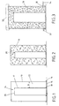
- Outer tube 10 and inner tube 12 stand with their respective lower end on a lid 14, the lid 14 via two concentric flanges 16, 18 with an internal thread corresponding external thread at the lower end of the outer tube 10 and the inner tube 12 is screwed on.
- the inner tube 12 is shorter than the outer tube 10 and ends correspondingly at a distance from the upper edge of the outer tube 10.
- the inner tube 12 is at the upper end with a steel plate 20 locked.
- the annular gap 22 and Room 24 filled with a reinforcement cage 26 made of steel ( Figure 2).
- the reinforcement can also be on the inner wall beforehand of the outer tube and / or on the outer wall of the inner tube attached, for example welded on.
- a heavy concrete aggregate is added to the annular gap 22 and the space 24 filled, which here from 20 wt .-% barite Grain fraction 4/8 mm, from 30 wt .-% barite of the grain fraction 8/16 mm and 50 wt .-% steel balls with a diameter between 5 and 8 mm in a homogeneous mixture (Figure 2).
- the outer tube 10 has two, offset by 180 ° to each other Openings 30, in each of which a tubular Adapter 32 is screwed in.
- the openings are at the bottom End of the outer tube 10 is arranged.
- a delivery line is then connected to the adapter 32 (shown schematically by arrow 34) connected.
- a cement / water / plasticizer mixture is then fed through the delivery line in the form of a viscous suspension Pressure injected into the annular gap 22.
- the suspension consists of cement type CEM I 42.5, a Water content of 35%, based on the cement and one 3% plasticizer (plasticizer here: melamine sulfonate), based on the cement content.
- Figure 3 is an approximately 50% degree of filling of the annular gap 22 identified by line 36.
- a steel plate is made 38 (shown in dashed lines in Figure 3) on the upper Welded end of the outer tube 10.
- the arrangement is then rotated through 180 ° (FIG. 4). at The container lid 14 can then be used as required other steel cover 40 to be replaced.
- the openings 30 on the finished container also closed.
- the 7-day compressive strength according to DIN 1048, part 2 of the heavy concrete is 26 N / mm 2 , the corresponding 28-day compressive strength is 46 N / mm 2 .
- the modulus of elasticity of the concrete was determined based on DIN 1048 Part 5 with 30,000 N / mm 2 .
Landscapes
- Physics & Mathematics (AREA)
- Engineering & Computer Science (AREA)
- General Engineering & Computer Science (AREA)
- High Energy & Nuclear Physics (AREA)
- Curing Cements, Concrete, And Artificial Stone (AREA)
- Filling Or Discharging Of Gas Storage Vessels (AREA)
- Containers Having Bodies Formed In One Piece (AREA)
- Packages (AREA)
- Manufacturing Of Tubular Articles Or Embedded Moulded Articles (AREA)
- Packging For Living Organisms, Food Or Medicinal Products That Are Sensitive To Environmental Conditiond (AREA)
Claims (15)
- Procédé pour la fabrication d'un conteneur pour le transport et pour le stockage de matériau à rayonnement radioactif, comportant les étapes suivantes :1.1 un tuyau intérieur en métal est introduit dans un tuyau extérieur en métal de telle façon qu'on ait un espace annulaire de largeur constante entre le tuyau intérieur et le tuyau extérieur,1.2 ensuite, l'espace annulaire est rempli avec un granulat ou un mélange de granulat, dont la grosseur de grain minimale est 2 mm et la grosseur de grain maximale 20 mm, au moins 95% de poids du granulat présentant une densité brute supérieure à 4,2 g/cm3,1.3 ensuite, on enfonce par au moins une ouverture sur l'extrémité côté fond du tuyau intérieur et/ou du tuyau extérieur une suspension faite de ciment, d'eau et de liquéfiant sous haute pression dans l'espace annulaire jusqu'à ce que la suspension ait atteint l'extrémité supérieure du tuyau extérieur en remplissant complètement les interstices présents au milieu du granulat,1.4 la suspension étant ajustée de telle façon que le béton formé conjointement avec le granulat présente une densité brute supérieure à 4.100 g/cm3 et le ciment pris dans l'espace annulaire conjointement avec le granulat présente une résistance à la pression du béton selon DIN 1048 partie 2 supérieure à 45 N/mm2 après vingt-huit jours.
- Procédé selon la revendication 1, avec lequel on utilise comme ciment un ciment Portland du type CEM I 42,5 ou supérieur.
- Procédé selon la revendication 1, avec lequel on utilise comme granulat de la baryte, du ferrophosphore, de la magnétite, du fer, du plomb, de l'hématite, du granulat de fonte en coquille ainsi que d'autres métaux ou mélanges des granulats précités.
- Procédé selon la revendication 3, avec lequel on utilise comme granulat un mélange de baryte, de ferrophosphore, de magnétite, d'hématite ou de mélanges de ces produits en combinaison avec des billes d'acier.
- Procédé selon la revendication 4, avec lequel on utilise comme granulat un mélange de baryte, de ferrophosphore, de magnétite, d'hématite ou de mélanges de ces produits dans les fractions granulométriques 4/8 mm et 8/16 mm en combinaison avec des billes d'acier avec un diamètre compris entre 4 et 10 mm.
- Procédé selon la revendication 4, avec lequel on utilise comme granulat un mélange de baryte, de ferrophosphore, de magnétite, d'hématite ou de mélanges de ces produits dans un pourcentage de poids de 15 à 25% pour une fraction granulométrique 4/8 mm et un pourcentage en poids compris entre 25 à 35% pour une fraction granulométrique 8/16 mm en combinaison avec 45 à 55% de poids de billes d'acier avec un diamètre compris entre 4 et 8 mm.
- Procédé selon la revendication 1, avec lequel on utilise un tuyau intérieur fermé sur l'extrémité supérieure qui est plus court que le tuyau extérieur, l'espace entre l'extrémité fermée supérieure du tuyau intérieur et le bord supérieur du tuyau extérieur étant également rempli avec du granulat et les interstices étant remplis avec la suspension au milieu du granulat.
- Procédé selon la revendication 1, avec lequel le tuyau intérieur et le tuyau extérieur sont fermés avec un couvercle en métal avant le chargement du granulat sur les extrémités inférieures.
- Procédé selon la revendication 1 ou 7, avec lequel, avant le chargement du granulat, une armature est introduite dans l'espace annulaire et/ou l'espace réalisé entre l'extrémité supérieure fermée du tuyau intérieur et l'extrémité ouverte du tuyau extérieur.
- Procédé selon la revendication 9, avec lequel on utilise comme armature une cage d'armature qui s'étend sensiblement sur tout le volume de l'espace annulaire et/ou de l'espace.
- Procédé selon la revendication 1, avec lequel l'extrémité supérieure ou inférieure ou l'extrémité supérieure et l'extrémité inférieure du tuyau extérieur est/sont fermée(s) de façon étanche après la prise de la suspension avec un couvercle en métal ou un capot en métal, au moins une couvercle en métal ou un capot en métal étant posé de façon amovible sur le tuyau extérieur.
- Conteneur pour le transport et pour le stockage de matériau à rayonnement radioactif avec les caractéristiques suivantes :12.1 le conteneur comprend un tuyau extérieur (10) en métal et un tuyau intérieur (12) en métal disposé dedans avec une distance égale à la périphérie en formant un espace annulaire (22) de largeur constante entre le tuyau intérieur et le tuyau extérieur (12, 10).12.2 l'espace annulaire (22) entre le tuyau intérieur et le tuyau extérieur (12, 10) est rempli avec un béton lourd, qui est à base d'un granulat ou mélange de granulat (28) avec une densité brute supérieure à 4,2 g/cm3 et un ciment remplissant des interstices au milieu du granulat, le béton lourd présentant une densité brute supérieure à 4.100 g/cm3 et une résistance à la pression pendant vingt-huit jours selon DIN 1048, partie 2, supérieure à 45 N/mm2.12.3 Le tuyau extérieur (10) et le tuyau intérieur (12) sont fermés à leurs extrémités avec un fond métallique (38) et un couvercle métallique (14), au moins le couvercle en métal (14) étant disposé de façon amovible.
- Conteneur selon la revendication 12, avec lequel le tuyau intérieur (12) se termine à distance avant l'extrémité inférieure du tuyau extérieur (10), est fermé sur cette extrémité, et entre l'extrémité inférieure fermée du tuyau intérieur (12) et l'extrémité inférieure du tuyau extérieur (10) est disposée une plaque de béton lourd qui est au contact du béton lourd présent dans l'espace annulaire.
- Conteneur selon la revendication 12 ou 13, sur lequel le béton lourd est armé.
- Conteneur selon la revendication 14, sur lequel l'armature comprend une cage d'armature (26).
Applications Claiming Priority (3)
| Application Number | Priority Date | Filing Date | Title |
|---|---|---|---|
| DE19725922 | 1997-06-19 | ||
| DE19725922A DE19725922C2 (de) | 1997-06-19 | 1997-06-19 | Verfahren zur Herstellung eines Behälters |
| PCT/DE1998/001608 WO1998059346A1 (fr) | 1997-06-19 | 1998-06-09 | Procede de production d'un conteneur, et conteneur ainsi produit |
Publications (2)
| Publication Number | Publication Date |
|---|---|
| EP0990237A1 EP0990237A1 (fr) | 2000-04-05 |
| EP0990237B1 true EP0990237B1 (fr) | 2002-08-07 |
Family
ID=7832941
Family Applications (1)
| Application Number | Title | Priority Date | Filing Date |
|---|---|---|---|
| EP98936155A Expired - Lifetime EP0990237B1 (fr) | 1997-06-19 | 1998-06-09 | Procede de production d'un conteneur, et conteneur ainsi produit |
Country Status (15)
| Country | Link |
|---|---|
| US (1) | US6518585B1 (fr) |
| EP (1) | EP0990237B1 (fr) |
| JP (1) | JP2001508874A (fr) |
| KR (1) | KR100320969B1 (fr) |
| CN (1) | CN1165915C (fr) |
| AU (1) | AU8531398A (fr) |
| CA (1) | CA2292589C (fr) |
| CZ (1) | CZ293385B6 (fr) |
| DE (2) | DE19725922C2 (fr) |
| EA (1) | EA001461B1 (fr) |
| ES (1) | ES2181250T3 (fr) |
| SK (1) | SK283640B6 (fr) |
| TW (1) | TW366501B (fr) |
| UA (1) | UA54529C2 (fr) |
| WO (1) | WO1998059346A1 (fr) |
Families Citing this family (12)
| Publication number | Priority date | Publication date | Assignee | Title |
|---|---|---|---|---|
| EP1103984B1 (fr) * | 1999-06-19 | 2002-09-18 | GNB Gesellschaft für Nuklear-Behälter mbH | Conteneur de transport et/ou de stockage d'objets radioactifs dégageant de la chaleur |
| ES2182452T3 (es) | 1999-12-15 | 2003-03-01 | Gnb Gmbh | Procedimiento para fabricar un recipiente de transporte y/o almacenamiento de objetos radiactivos. |
| US7014059B2 (en) * | 2002-05-17 | 2006-03-21 | Master Lite Security Products, Inc. | Explosion resistant waste container |
| SE525468C2 (sv) * | 2002-11-29 | 2005-03-01 | Oyster Internat Nv C O H B Man | Behållaranordning för förvaring av riskmaterial, i synnerhet för slutförvaring av kärnbränsle, och sätt för dess framställning |
| DE10327466B4 (de) * | 2003-01-13 | 2008-08-07 | Jan Forster | Baukörper für Strahlenschutzbauwerke |
| JP2006038465A (ja) * | 2004-07-22 | 2006-02-09 | Kumagai Gumi Co Ltd | 放射線遮蔽用コンクリート組成物 |
| US9443625B2 (en) * | 2005-03-25 | 2016-09-13 | Holtec International, Inc. | Method of storing high level radioactive waste |
| ES2296522B1 (es) * | 2006-05-26 | 2009-04-01 | Europea De Minerales Y Derivados, S.L. | Masa pesada para la fabricacion de productos con alta capacidad de radio-proteccion. |
| JP5545788B1 (ja) * | 2013-07-07 | 2014-07-09 | 株式会社安藤・間 | 放射線遮蔽容器、放射線遮蔽函体、及び放射性廃棄物の収容方法 |
| CN108122650A (zh) * | 2016-11-29 | 2018-06-05 | 黄璜 | 可适变异形衬管 |
| US20220367078A1 (en) * | 2021-05-17 | 2022-11-17 | Holtec International | Stackable nuclear waste storage system |
| DE102022202475A1 (de) | 2022-03-11 | 2023-09-14 | Fraunhofer-Gesellschaft zur Förderung der angewandten Forschung eingetragener Verein | Mehrlagiger Werkstoffverbund, Bauteil umfassend den mehrlagigen Werkstoffverbund, Verfahren zu deren Herstellung und deren Verwendung |
Family Cites Families (15)
| Publication number | Priority date | Publication date | Assignee | Title |
|---|---|---|---|---|
| US3742985A (en) * | 1967-01-31 | 1973-07-03 | Chemstress Ind Inc | Reinforced pipe |
| DE2817193A1 (de) * | 1978-04-20 | 1979-10-31 | Transnuklear Gmbh | Abschirmbehaelter fuer den transport und die lagerung bestrahlter brennelemente |
| FR2516292A1 (fr) * | 1981-11-10 | 1983-05-13 | Stockage Assainissement | Coulis special d'injection et son utilisation pour le stockage dans le sol de dechets radioactifs |
| DE3331892C2 (de) * | 1983-09-03 | 1986-01-23 | Kernforschungsanlage Jülich GmbH, 5170 Jülich | Transport- und Lagerbehälter für radioaktives Material |
| DE3635500A1 (de) * | 1986-10-18 | 1988-05-11 | Kernforschungsanlage Juelich | Schwerbeton zur herstellung eines transportbehaelters fuer radioaktives material |
| DE3709315C2 (de) * | 1987-03-21 | 1996-04-25 | Nuklear Service Gmbh Gns | Verfahren zum Einlagern von radioaktiven Abfallstoffen |
| US5008045A (en) * | 1989-03-23 | 1991-04-16 | Alternative Technologies For Waste, Inc. | Method and apparatus for centrifugally casting hazardous waste |
| US5063967A (en) * | 1989-12-06 | 1991-11-12 | Stephens Patrick J | Pumpable cement grout |
| JP3084123B2 (ja) * | 1992-04-15 | 2000-09-04 | ジオスター株式会社 | ボックスカルバートの製造方法 |
| US5457263A (en) * | 1994-02-14 | 1995-10-10 | University Of New Mexico | Method for containing radioactive waste |
| JP3332687B2 (ja) * | 1995-10-03 | 2002-10-07 | 株式会社東芝 | 原子炉格納容器 |
| JP3020050B2 (ja) * | 1995-12-20 | 2000-03-15 | 五洋建設株式会社 | コンクリート充填方法 |
| US5819186A (en) * | 1996-04-26 | 1998-10-06 | Stephens; Patrick J. | Cellular grout radiation barrier |
| US6299950B1 (en) * | 1997-09-30 | 2001-10-09 | Bwxt Y12 Llc | Fireproof impact limiter aggregate packaging inside shipping containers |
| US5949084A (en) * | 1998-06-30 | 1999-09-07 | Schwartz; Martin W. | Radioactive material storage vessel |
-
1997
- 1997-06-19 DE DE19725922A patent/DE19725922C2/de not_active Expired - Fee Related
-
1998
- 1998-06-09 SK SK1751-99A patent/SK283640B6/sk not_active IP Right Cessation
- 1998-06-09 AU AU85313/98A patent/AU8531398A/en not_active Abandoned
- 1998-06-09 CZ CZ19994338A patent/CZ293385B6/cs not_active IP Right Cessation
- 1998-06-09 ES ES98936155T patent/ES2181250T3/es not_active Expired - Lifetime
- 1998-06-09 JP JP50355399A patent/JP2001508874A/ja active Pending
- 1998-06-09 WO PCT/DE1998/001608 patent/WO1998059346A1/fr active IP Right Grant
- 1998-06-09 CA CA002292589A patent/CA2292589C/fr not_active Expired - Lifetime
- 1998-06-09 EA EA199901064A patent/EA001461B1/ru not_active IP Right Cessation
- 1998-06-09 US US09/446,502 patent/US6518585B1/en not_active Expired - Fee Related
- 1998-06-09 EP EP98936155A patent/EP0990237B1/fr not_active Expired - Lifetime
- 1998-06-09 DE DE59805117T patent/DE59805117D1/de not_active Expired - Lifetime
- 1998-06-09 CN CNB988064073A patent/CN1165915C/zh not_active Expired - Fee Related
- 1998-06-11 TW TW087109302A patent/TW366501B/zh not_active IP Right Cessation
- 1998-06-19 KR KR1019980023036A patent/KR100320969B1/ko not_active IP Right Cessation
- 1998-09-06 UA UA2000010320A patent/UA54529C2/uk unknown
Also Published As
| Publication number | Publication date |
|---|---|
| SK283640B6 (sk) | 2003-11-04 |
| DE59805117D1 (de) | 2002-09-12 |
| DE19725922A1 (de) | 1998-12-24 |
| JP2001508874A (ja) | 2001-07-03 |
| CZ433899A3 (cs) | 2000-04-12 |
| WO1998059346A1 (fr) | 1998-12-30 |
| KR100320969B1 (ko) | 2002-05-13 |
| US6518585B1 (en) | 2003-02-11 |
| UA54529C2 (uk) | 2003-03-17 |
| CN1261456A (zh) | 2000-07-26 |
| CZ293385B6 (cs) | 2004-04-14 |
| TW366501B (en) | 1999-08-11 |
| CA2292589A1 (fr) | 1998-12-30 |
| DE19725922C2 (de) | 2000-07-20 |
| CN1165915C (zh) | 2004-09-08 |
| SK175199A3 (en) | 2000-06-12 |
| CA2292589C (fr) | 2003-02-25 |
| AU8531398A (en) | 1999-01-04 |
| ES2181250T3 (es) | 2003-02-16 |
| KR19990007116A (ko) | 1999-01-25 |
| EA199901064A1 (ru) | 2000-08-28 |
| EA001461B1 (ru) | 2001-04-23 |
| EP0990237A1 (fr) | 2000-04-05 |
Similar Documents
| Publication | Publication Date | Title |
|---|---|---|
| EP0990237B1 (fr) | Procede de production d'un conteneur, et conteneur ainsi produit | |
| DE19725922C9 (de) | Verfahren zur Herstellung eines Behälters | |
| WO2000010935A2 (fr) | Beton et enveloppe de protection contre les radiations | |
| DE1166392B (de) | Verfahren und Einrichtung zum Beseitigen waessrigen Atommuells | |
| DE102007044846A1 (de) | Ortsbeweglicher Tank und Tankcontainer zum Transport von V erflüssigtem Gas | |
| DE1810663A1 (de) | Vorgespannter Betondruckkessel | |
| DE3437534A1 (de) | Explosionskammer | |
| DE2442783A1 (de) | Verbindung von koerpern | |
| CH718234B1 (de) | Vorgespanntes kreisförmiges Spanngurt-Trägersystem und Verfahren zur Steuerung der Verformung des vorgespannten kreisförmigen Spanngurt-Trägersystems. | |
| EP0264521B1 (fr) | Conteneur à deux parois pour matériaux radioactifs | |
| EP0250573B1 (fr) | Beton resistant a la traction se composant de ciment, d'agregats et d'eau | |
| DE19708899C2 (de) | Verfahren zum Transport und zur Lagerung von abgebrannten Brennelementen und Neutronenabsorbern für die Durchführung des Verfahrens | |
| DE2648477C3 (de) | Verbundausbau für Bergbauschächte | |
| DE2049981A1 (de) | Abschaltstab für Kernreaktoren mit einer Schuttung vorzugsweise kugelförmiger Betnebselemente | |
| DE3227512A1 (de) | Verlorener abschirmbehaelter fuer radioaktive abfaelle | |
| DE19757843C1 (de) | Lagerbehälter für die Zwischen- und/oder Endlagerung abgebrannter Brennelemente | |
| CH691691A5 (de) | Stütze, insbesondere Stahlbetonstütze. | |
| CH664415A5 (de) | Rotationssymmetrischer sicherheitsbehaelter. | |
| DE2641352C2 (de) | Radiale Berstsicherung fur Druckbehälter, insbesondere für Kernreaktordruckbehälter | |
| DE2261473A1 (de) | Armiereinrichtung fuer spannbetonelemente | |
| DE1299112B (de) | Hochdruckbehaelter aus Stahlbeton | |
| DE1471517C3 (de) | Verfahren zur Herstellung eines frostbeständigen Injektionsmörtels | |
| Kucherer | Device to absorb solid radioactive waste suspended in water | |
| AT291693B (de) | Druckrohr mit Außenverstärkung für Wasserkraftanlagen od.dgl. | |
| CH337427A (de) | Unterirdischer Schutzraum und Verfahren zur Herstellung desselben |
Legal Events
| Date | Code | Title | Description |
|---|---|---|---|
| PUAI | Public reference made under article 153(3) epc to a published international application that has entered the european phase |
Free format text: ORIGINAL CODE: 0009012 |
|
| 17P | Request for examination filed |
Effective date: 19991106 |
|
| AK | Designated contracting states |
Kind code of ref document: A1 Designated state(s): BE CH DE ES FR GB IT LI NL |
|
| AX | Request for extension of the european patent |
Free format text: LT PAYMENT 19991106 |
|
| GRAG | Despatch of communication of intention to grant |
Free format text: ORIGINAL CODE: EPIDOS AGRA |
|
| 17Q | First examination report despatched |
Effective date: 20010629 |
|
| RAP1 | Party data changed (applicant data changed or rights of an application transferred) |
Owner name: GNB GESELLSCHAFT FUER NUKLEARBEHAELTER MBH |
|
| RAP3 | Party data changed (applicant data changed or rights of an application transferred) |
Owner name: GNB GESELLSCHAFT FUER NUKLEAR-BEHAELTER MBH |
|
| GRAG | Despatch of communication of intention to grant |
Free format text: ORIGINAL CODE: EPIDOS AGRA |
|
| GRAH | Despatch of communication of intention to grant a patent |
Free format text: ORIGINAL CODE: EPIDOS IGRA |
|
| GRAH | Despatch of communication of intention to grant a patent |
Free format text: ORIGINAL CODE: EPIDOS IGRA |
|
| GRAA | (expected) grant |
Free format text: ORIGINAL CODE: 0009210 |
|
| AK | Designated contracting states |
Kind code of ref document: B1 Designated state(s): BE CH DE ES FR GB IT LI NL |
|
| AX | Request for extension of the european patent |
Free format text: LT PAYMENT 19991106 |
|
| REG | Reference to a national code |
Ref country code: GB Ref legal event code: FG4D Free format text: NOT ENGLISH |
|
| REG | Reference to a national code |
Ref country code: CH Ref legal event code: EP |
|
| REF | Corresponds to: |
Ref document number: 59805117 Country of ref document: DE Date of ref document: 20020912 |
|
| REG | Reference to a national code |
Ref country code: CH Ref legal event code: NV Representative=s name: HANS RUDOLF GACHNANG PATENTANWALT |
|
| GBT | Gb: translation of ep patent filed (gb section 77(6)(a)/1977) |
Effective date: 20021025 |
|
| REG | Reference to a national code |
Ref country code: ES Ref legal event code: FG2A Ref document number: 2181250 Country of ref document: ES Kind code of ref document: T3 |
|
| ET | Fr: translation filed | ||
| PLBE | No opposition filed within time limit |
Free format text: ORIGINAL CODE: 0009261 |
|
| STAA | Information on the status of an ep patent application or granted ep patent |
Free format text: STATUS: NO OPPOSITION FILED WITHIN TIME LIMIT |
|
| 26N | No opposition filed |
Effective date: 20030508 |
|
| PGFP | Annual fee paid to national office [announced via postgrant information from national office to epo] |
Ref country code: GB Payment date: 20040527 Year of fee payment: 7 |
|
| PGFP | Annual fee paid to national office [announced via postgrant information from national office to epo] |
Ref country code: NL Payment date: 20040617 Year of fee payment: 7 |
|
| PGFP | Annual fee paid to national office [announced via postgrant information from national office to epo] |
Ref country code: BE Payment date: 20040623 Year of fee payment: 7 |
|
| PG25 | Lapsed in a contracting state [announced via postgrant information from national office to epo] |
Ref country code: GB Free format text: LAPSE BECAUSE OF NON-PAYMENT OF DUE FEES Effective date: 20050609 |
|
| PG25 | Lapsed in a contracting state [announced via postgrant information from national office to epo] |
Ref country code: BE Free format text: LAPSE BECAUSE OF NON-PAYMENT OF DUE FEES Effective date: 20050630 |
|
| REG | Reference to a national code |
Ref country code: CH Ref legal event code: PFA Owner name: GNS GESELLSCHAFT FUER NUKLEAR-SERVICE MBH Free format text: GNB GESELLSCHAFT FUER NUKLEAR-BEHAELTER MBH#HOLLESTRASSE 7A#45127 ESSEN (DE) -TRANSFER TO- GNS GESELLSCHAFT FUER NUKLEAR-SERVICE MBH#HOLLESTRASSE 7A#45127 ESSEN (DE) |
|
| REG | Reference to a national code |
Ref country code: ES Ref legal event code: PC2A |
|
| PG25 | Lapsed in a contracting state [announced via postgrant information from national office to epo] |
Ref country code: NL Free format text: LAPSE BECAUSE OF NON-PAYMENT OF DUE FEES Effective date: 20060101 |
|
| GBPC | Gb: european patent ceased through non-payment of renewal fee |
Effective date: 20050609 |
|
| NLV4 | Nl: lapsed or anulled due to non-payment of the annual fee |
Effective date: 20060101 |
|
| REG | Reference to a national code |
Ref country code: FR Ref legal event code: TP |
|
| BERE | Be: lapsed |
Owner name: G.- FUR NUKLEAR-BEHALTER M.B.H. *GNB Effective date: 20050630 |
|
| REG | Reference to a national code |
Ref country code: CH Ref legal event code: NV Representative=s name: GACHNANG AG PATENTANWAELTE, CH |
|
| REG | Reference to a national code |
Ref country code: FR Ref legal event code: PLFP Year of fee payment: 19 |
|
| REG | Reference to a national code |
Ref country code: FR Ref legal event code: PLFP Year of fee payment: 20 |
|
| PGFP | Annual fee paid to national office [announced via postgrant information from national office to epo] |
Ref country code: CH Payment date: 20170626 Year of fee payment: 20 Ref country code: DE Payment date: 20170517 Year of fee payment: 20 Ref country code: FR Payment date: 20170621 Year of fee payment: 20 |
|
| PGFP | Annual fee paid to national office [announced via postgrant information from national office to epo] |
Ref country code: IT Payment date: 20170622 Year of fee payment: 20 |
|
| PGFP | Annual fee paid to national office [announced via postgrant information from national office to epo] |
Ref country code: ES Payment date: 20170703 Year of fee payment: 20 |
|
| REG | Reference to a national code |
Ref country code: DE Ref legal event code: R071 Ref document number: 59805117 Country of ref document: DE |
|
| REG | Reference to a national code |
Ref country code: CH Ref legal event code: PL |
|
| REG | Reference to a national code |
Ref country code: ES Ref legal event code: FD2A Effective date: 20200805 |
|
| PG25 | Lapsed in a contracting state [announced via postgrant information from national office to epo] |
Ref country code: ES Free format text: LAPSE BECAUSE OF EXPIRATION OF PROTECTION Effective date: 20180610 |