EP0990237B1 - Container and method for producing a container - Google Patents
Container and method for producing a container Download PDFInfo
- Publication number
- EP0990237B1 EP0990237B1 EP98936155A EP98936155A EP0990237B1 EP 0990237 B1 EP0990237 B1 EP 0990237B1 EP 98936155 A EP98936155 A EP 98936155A EP 98936155 A EP98936155 A EP 98936155A EP 0990237 B1 EP0990237 B1 EP 0990237B1
- Authority
- EP
- European Patent Office
- Prior art keywords
- aggregate
- outer tube
- annular gap
- container
- metal
- Prior art date
- Legal status (The legal status is an assumption and is not a legal conclusion. Google has not performed a legal analysis and makes no representation as to the accuracy of the status listed.)
- Expired - Lifetime
Links
Images

Classifications
-
- G—PHYSICS
- G21—NUCLEAR PHYSICS; NUCLEAR ENGINEERING
- G21F—PROTECTION AGAINST X-RADIATION, GAMMA RADIATION, CORPUSCULAR RADIATION OR PARTICLE BOMBARDMENT; TREATING RADIOACTIVELY CONTAMINATED MATERIAL; DECONTAMINATION ARRANGEMENTS THEREFOR
- G21F5/00—Transportable or portable shielded containers
Definitions
- the invention relates to a method for producing a Container for the transport and storage of radioactive radiating material as well as a container with which to radioactive radiating material can be transported and stored can.
- Such containers have so-called in the embodiment "Castor container” was very important in the past obtained. They serve radioactive material, for example spent fuel elements from nuclear reactors, from the power plant to an intermediate or final storage point transport.
- the invention is based on these aspects Task based on a method for producing a corresponding Container or one of the aforementioned Provide sufficient container.
- Radioactive rays include alpha rays, beta rays, Gamma rays and neutron rays.
- Alpha and Beta rays generally have such short ranges that for their shielding low material thicknesses (order of magnitude: a few millimeters) are sufficient.
- the invention is based on the knowledge that the Shielding effect of such steel-reinforced concrete containers a special selection of heavy concrete between steel walls can be achieved.
- the essential aspect of this process is the special application technique of heavy concrete between the called metal walls.
- cement stands for everyone Types of hydraulic binders. To be favoured however, Portland cements are used, namely Portland cements of type CEM I 42.5 or higher (e.g. CEM I 52.5).
- Surcharges that have the required bulk density are for example barite, ferrophosphorus, magnetite, iron (Steel), lead, hematite and chilled cast granulate and others
- Metals, especially heavy metals, with the supplements can be used individually or in mixtures.
- this term particularly includes steel pipes and here in particular steel pipes with a circular cross section, albeit other cross-sectional shapes, for example Polygons can be used.
- One embodiment of the method provides an inner tube to use which is closed at its upper end and is shorter than the outer tube.
- outer tube and inner tube for example on a floor (one Plate) and then not just the annulus between the inner and outer pipe filled with the aggregate, but also the space between the top closed end of the inner tube and the upper edge of the outer tube. Subsequently In addition to the annulus, the space between the closed end of the inner tube and the top edge of the outer pipe with the cement / water / plasticizer suspension filled. In this way a kind arises "Concrete cover", which in later use (after turning around 180 °) forms the bottom of the container.
- a metal / steel plate attached to the upper edge of the outer tube for Example can be screwed on or welded on.
- the stability of the container is significantly improved, if reinforcement in the Annular gap or that between the upper closed end of the inner tube and the open end of the Outer tube trained space is inserted. hereby is also the heat dissipation during the hydration of the cement improved.
- Such reinforcement can, for example, consist of one Reinforcement cage exist, which is essentially about total volume of the annular gap or the named Extends.
- the width of the annular gap is, for example 20 to 30 cm. Also the “concrete floor slab” can have an appropriate thickness.
- the container can be designed in this way be that the inner tube at a distance from the lower end of the Outer tube ends, is closed at this end and between the closed lower end of the inner tube and a heavy concrete slab is available at the lower end of the outer tube which is material-locking with that in the annular gap Is heavy concrete.
- This embodiment describes the container in Use state. Inner and outer tubes are used for the production arranged rotated by 180 °, as described above.
- the heavy concrete can be armored, the armouring for example there is a reinforcement cage.
- Outer tube 10 and inner tube 12 stand with their respective lower end on a lid 14, the lid 14 via two concentric flanges 16, 18 with an internal thread corresponding external thread at the lower end of the outer tube 10 and the inner tube 12 is screwed on.
- the inner tube 12 is shorter than the outer tube 10 and ends correspondingly at a distance from the upper edge of the outer tube 10.
- the inner tube 12 is at the upper end with a steel plate 20 locked.
- the annular gap 22 and Room 24 filled with a reinforcement cage 26 made of steel ( Figure 2).
- the reinforcement can also be on the inner wall beforehand of the outer tube and / or on the outer wall of the inner tube attached, for example welded on.
- a heavy concrete aggregate is added to the annular gap 22 and the space 24 filled, which here from 20 wt .-% barite Grain fraction 4/8 mm, from 30 wt .-% barite of the grain fraction 8/16 mm and 50 wt .-% steel balls with a diameter between 5 and 8 mm in a homogeneous mixture (Figure 2).
- the outer tube 10 has two, offset by 180 ° to each other Openings 30, in each of which a tubular Adapter 32 is screwed in.
- the openings are at the bottom End of the outer tube 10 is arranged.
- a delivery line is then connected to the adapter 32 (shown schematically by arrow 34) connected.
- a cement / water / plasticizer mixture is then fed through the delivery line in the form of a viscous suspension Pressure injected into the annular gap 22.
- the suspension consists of cement type CEM I 42.5, a Water content of 35%, based on the cement and one 3% plasticizer (plasticizer here: melamine sulfonate), based on the cement content.
- Figure 3 is an approximately 50% degree of filling of the annular gap 22 identified by line 36.
- a steel plate is made 38 (shown in dashed lines in Figure 3) on the upper Welded end of the outer tube 10.
- the arrangement is then rotated through 180 ° (FIG. 4). at The container lid 14 can then be used as required other steel cover 40 to be replaced.
- the openings 30 on the finished container also closed.
- the 7-day compressive strength according to DIN 1048, part 2 of the heavy concrete is 26 N / mm 2 , the corresponding 28-day compressive strength is 46 N / mm 2 .
- the modulus of elasticity of the concrete was determined based on DIN 1048 Part 5 with 30,000 N / mm 2 .
Landscapes
- Physics & Mathematics (AREA)
- Engineering & Computer Science (AREA)
- General Engineering & Computer Science (AREA)
- High Energy & Nuclear Physics (AREA)
- Curing Cements, Concrete, And Artificial Stone (AREA)
- Filling Or Discharging Of Gas Storage Vessels (AREA)
- Containers Having Bodies Formed In One Piece (AREA)
- Packages (AREA)
- Manufacturing Of Tubular Articles Or Embedded Moulded Articles (AREA)
- Packging For Living Organisms, Food Or Medicinal Products That Are Sensitive To Environmental Conditiond (AREA)
Description
Die Erfindung betrifft ein Verfahren zur Herstellung eines Behälters zum Transport und zur Lagerung von radioaktiv strahlendem Material sowie einen Behälter, mit dem radioaktiv strahlendes Material transportiert und gelagert werden kann.The invention relates to a method for producing a Container for the transport and storage of radioactive radiating material as well as a container with which to radioactive radiating material can be transported and stored can.
Derartige Behälter haben in der Ausführungsform sogenannter "Castor-Behälter" in der Vergangenheit große Bedeutung erlangt. Sie dienen dazu, radioaktiv strahlendes Material, beispielsweise abgebrannte Brennelemente aus Kernreaktoren, vom Kraftwerk zu einer Zwischen- oder Endlagerungsstelle zu transportieren. Such containers have so-called in the embodiment "Castor container" was very important in the past obtained. They serve radioactive material, for example spent fuel elements from nuclear reactors, from the power plant to an intermediate or final storage point transport.
Dabei sind teilweise große Strecken zu überwinden. Ein solcher Transport erfordert ein extrem hohes Maß an Sicherheit. Dies gilt nicht nur für die Transportfahrzeuge (Lastkraftwagen, Züge, Schiffe), sondern vor allem auch für die Behälter, in denen beispielsweise die Brennelemente transportiert werden.Large distances have to be covered in some cases. On such transport requires an extremely high level of security. This does not only apply to transport vehicles (trucks, Trains, ships), but especially for those Containers in which, for example, the fuel assemblies be transported.
Dabei geht es vor allem um zwei Sicherheitsaspekte:
Insoweit werden an die radioaktive Abschirmung des Behälters ebenso hohe Anforderungen gestellt wie an dessen Festigkeit und Stabilität.To this extent, the radioactive shielding of the container just as high demands as on its strength and stability.
Unter Zugrundelegung dieser Aspekte liegt der Erfindung die Aufgabe zugrunde, ein Verfahren zur Herstellung eines entsprechenden Behälters beziehungsweise einen den vorgenannten Anforderungen genügenden Behälter zur Verfügung zu stellen.The invention is based on these aspects Task based on a method for producing a corresponding Container or one of the aforementioned Provide sufficient container.
Zu den radioaktiven Strahlen gehören Alpha-Strahlen, Beta-Strahlen, Gamma-Strahlen und Neutronenstrahlen. Alpha- und Beta-Strahlen haben im allgemeinen so kurze Reichweiten, daß für ihre Abschirmung geringe Materialdicken (Größenordnung: einige Millimeter) genügen. Bei der Projektierung eines Strahlenschutzbehälters kommt es deshalb in der Hauptsache auf die Schwächung und Absorption der Neutronen- und Gamma-Strahlung an. Radioactive rays include alpha rays, beta rays, Gamma rays and neutron rays. Alpha and Beta rays generally have such short ranges that for their shielding low material thicknesses (order of magnitude: a few millimeters) are sufficient. When planning a The main reason why radiation protection containers occur on the attenuation and absorption of neutron and gamma radiation on.
In diesem Zusammenhang ist es bekannt, daß die Masse und damit die Rohdichte einer entsprechenden Behälterwandung eine wesentliche Größe ist.In this context it is known that the mass and thus the bulk density of a corresponding container wall is an essential size.
Insoweit wurden in der Vergangenheit Stahlbehälter wie der genannte Castor-Behälter verwendet. Daneben sind sogenannte Stahl-Stahlbetonbehälter bekannt, die aus einer Kombination Stahl/Beton aufgebaut sind.To that extent, steel tanks have been used in the past called Castor container used. There are also so-called Steel-reinforced concrete container known from a combination Steel / concrete are built.
Der Erfindung liegt die Erkenntnis zugrunde, daß die Abschirmwirkung derartiger Stahl-Stahlbetonbehälter durch eine spezielle Auswahl eines Schwerbetons zwischen Stahlwänden erreicht werden kann.The invention is based on the knowledge that the Shielding effect of such steel-reinforced concrete containers a special selection of heavy concrete between steel walls can be achieved.
In ihrer allgemeinsten Ausführungsform schlägt die Erfindung ein Verfahren zur Herstellung eines Behälters zum Transport und zur Lagerung von radioaktiv strahlendem Material mit folgenden Merkmalen vor:
- ein Innenrohr aus Metall wird in einem Außenrohr aus Metall so eingestellt, daß zwischen Innen- und Außenrohr ein Ringspalt konstanter Breite entsteht,
- danach wird der Ringspalt mit einem Zuschlag oder einem
Zuschlaggemisch ausgefüllt, dessen minimale Korngröße 2 mm
und dessen
maximale Korngröße 20 mm beträgt, wobei mindestens 95 Gew.-% des Zuschlages eine Rohdichte > 4,2 g/cm3 aufweisen, - anschließend wird durch mindestens eine Öffnung am bodenseitigen Ende des Innen- und/oder Außenrohres eine Suspension aus Zement, Wasser und einem Verlüssiger unter Hochdruck in den Ringspalt eingepreßt, bis die Suspension unter vollständiger Verfüllung der zwischen dem Zuschlag vorhandenen Zwickel das obere Ende des Außenrohres erreicht hat,
- wobei die Suspension aus Zement, Wasser und Verflüssiger so eingestellt wird, daß der (gemeinsam mit dem Zuschlag) entstehende Beton eine Rohdichte > 4.100 g/cm3 und eine Beton-Druckfestigkeit gemäß DIN 1048 Teil 2 von > 45 N/mm2 nach 28 Tagen aufweist.
- an inner tube made of metal is set in an outer tube made of metal so that an annular gap of constant width is formed between the inner and outer tubes,
- the annular gap is then filled with an aggregate or an aggregate mixture whose minimum grain size is 2 mm and whose maximum grain size is 20 mm, at least 95% by weight of the aggregate having a bulk density> 4.2 g / cm 3 ,
- a suspension of cement, water and a condenser is then pressed under high pressure into the annular gap through at least one opening at the bottom end of the inner and / or outer tube until the suspension reaches the upper end of the outer tube with complete filling of the gusset between the aggregate Has,
- whereby the suspension of cement, water and plasticizer is adjusted so that the concrete (together with the aggregate) has a bulk density> 4,100 g / cm 3 and a concrete compressive strength according to DIN 1048 Part 2 of> 45 N / mm 2 after 28 Days.
Der wesentliche Aspekt dieses Verfahrens besteht in der speziellen Einbringtechnik des Schwerbetons zwischen die genannten Metallwände.The essential aspect of this process is the special application technique of heavy concrete between the called metal walls.
Mit einer fertig aufbereiteten Betonmischung, die in den Ringspalt eingefüllt würde, ließen sich die geforderten Rohdichten und Druckfestigkeiten ebensowenig erreichen wie die notwendige Abschirmung gegen radioaktive Strahlung.With a ready prepared concrete mix that is in the Would be filled in, the required Reach densities and compressive strengths just as little as the necessary shielding against radioactive radiation.
Dies gelingt erst durch die Auswahl spezieller Zuschläge, die in einem ersten Verfahrensschritt in den Ringspalt gefüllt werden und durch die sich daran anschließende Injektion des Zementleims unter Druck, wobei der Verfüllungsgrad des Zementleims maßgeblich dadurch optimiert wird, daß die Injektion von unten nach oben erfolgt. Auf diese Weise kann eine hervorragende und nahezu optimale Verfüllung der Zwickel zwischen den Zuschlagteilen erfolgen und damit ein dichter, hochfester Beton im Ringraum ausgebildet werden.This is only possible through the selection of special supplements, in the first step in the annular gap be filled and by the subsequent Injection of the cement paste under pressure, the The degree of filling of the cement paste has been significantly optimized as a result is that the injection is made from the bottom up. On this way can be excellent and almost optimal The gusset is filled between the aggregate parts and thus a dense, high-strength concrete in the annulus be formed.
Der Begriff Zement steht dabei stellvertretend für alle Arten von hydraulischen Bindemitteln. Bevorzugt werden jedoch Portlandzemente eingesetzt, und zwar Portlandzemente des Typs CEM I 42,5 oder höherwertig (zum Beispiel CEM I 52,5). The term cement stands for everyone Types of hydraulic binders. To be favoured however, Portland cements are used, namely Portland cements of type CEM I 42.5 or higher (e.g. CEM I 52.5).
Zuschläge, die die geforderte Rohdichte aufweisen, sind beispielsweise Baryt, Ferrophosphor, Magnetit, Eisen (Stahl), Blei, Haematit und Hartgußgranulat sowie andere Metalle, insbesondere Schwermetalle, wobei die Zuschläge einzeln oder in Mischungen eingesetzt werden können.Surcharges that have the required bulk density are for example barite, ferrophosphorus, magnetite, iron (Steel), lead, hematite and chilled cast granulate and others Metals, especially heavy metals, with the supplements can be used individually or in mixtures.
Eine Mischung aus Baryt, Ferrophosphor, Magnetit, Haematit oder Mischungen daraus in Kombination mit Stahlkugeln führt zu sehr guten Dichte- und Druckfestigkeitswerten des Frischbetons beziehungsweise ausgehärteten Betons.A mixture of barite, ferrophosphorus, magnetite, haematite or mixtures thereof in combination with steel balls to very good density and compressive strength values of the fresh concrete or hardened concrete.
In Vorversuchen wurden verschiedene Zuschlaggemische getestet. Besonders günstige Eigenschaften zeigen danach Zuschlaggemische aus Baryt, Ferrophosphor, Magnetit, Haematit oder Mischungen daraus in den Kornfraktionen 4 bis 8 mm sowie 8 bis 16 mm in Kombination mit Stahlkugeln mit einem Durchmesser zwischen 4 und 10 mm. Die Stahlkugeln können auch eine sphärische Form aufweisen und ganz oder teilweise durch Bleikugeln oder Hartgußgranulat ersetzt werden.Various aggregate mixtures were used in preliminary tests tested. This shows particularly favorable properties Additive mixtures of barite, ferrophosphorus, magnetite, Haematite or mixtures thereof in the grain fractions 4 to 8 mm and 8 to 16 mm in combination with steel balls with a diameter between 4 and 10 mm. The steel balls can also have a spherical shape and all or partly replaced by lead balls or chilled granules become.
Die Mengenanteile der einzelnen Zuschlag-Komponenten können dabei beispielsweise wie folgt sein:
- Zuschlag der Kornfraktion 4/8: 15 bis 25 Gew.-%
- Zuschlag der Kornfraktion 8/16: 15 bis 25 Gew.-%
- Stahlkugeln mit einem Durchmesser zwischen 4 und 10 mm: 45 bis 55 Gew.-%.
- Addition of the grain fraction 4/8: 15 to 25% by weight
- Surcharge of grain fraction 8/16: 15 to 25% by weight
- Steel balls with a diameter between 4 and 10 mm: 45 to 55% by weight.
Soweit vorstehend von Metallrohren gesprochen wurde, so umfaßt dieser Begriff insbesondere Stahlrohre und hier wiederum insbesondere Stahlrohre mit Kreisquerschnitt, wenngleich auch andere Querschnittsformen, beispielsweise Polygone, eingesetzt werden können. Insofar as metal pipes have been mentioned above, so this term particularly includes steel pipes and here in particular steel pipes with a circular cross section, albeit other cross-sectional shapes, for example Polygons can be used.
Eine Ausführungsform des Verfahrens sieht vor, ein Innenrohr zu verwenden, welches an seinem oberen Ende geschlossen und kürzer als das Außenrohr ist. In diesem Fall werden Außenrohr und Innenrohr beispielsweise auf einen Boden (eine Platte) aufgestellt und anschließend nicht nur der Ringraum zwischen Innen- und Außenrohr mit dem Zuschlag verfüllt, sondern auch der Raum zwischen dem oberen geschlossenen Ende des Innenrohres und dem oberen Rand des Außenrohres. Anschließend wird neben dem Ringraum auch der Raum zwischen dem geschlossenen Ende des Innenrohres und dem oberen Rand des Außenrohres mit der Zement/Wasser/Verflüssiger-Suspension verfüllt. Auf diese Weise entsteht eine Art "Betondeckel", der in der späteren Anwendung (nach Drehen um 180°) den Behälterboden bildet. Zusätzlich kann eine Metall-/Stahlplatte am oberen Rand des Außenrohres befestigt, zum Beispiel aufgeschraubt oder angeschweißt werden.One embodiment of the method provides an inner tube to use which is closed at its upper end and is shorter than the outer tube. In this case, outer tube and inner tube, for example on a floor (one Plate) and then not just the annulus between the inner and outer pipe filled with the aggregate, but also the space between the top closed end of the inner tube and the upper edge of the outer tube. Subsequently In addition to the annulus, the space between the closed end of the inner tube and the top edge of the outer pipe with the cement / water / plasticizer suspension filled. In this way a kind arises "Concrete cover", which in later use (after turning around 180 °) forms the bottom of the container. In addition, a metal / steel plate attached to the upper edge of the outer tube for Example can be screwed on or welded on.
Das Herstellungsverfahren wird dadurch vereinfacht, wenn Innenrohr und Außenrohr vor dem Einfüllen des Zuschlages an ihrem unteren Ende mit einem Metall-/Stahldeckel verschlossen werden. Vorzugsweise geschieht dies durch Aufschrauben auf die korrespondierenden Rohrenden. Auf diese Weise wird die koaxiale Ausrichtung von Innen- und Außenrohr erleichtert, und zwar auch beim Einfüllen des Zuschlages beziehungsweise beim Injizieren der Zementsuspension.The manufacturing process is simplified if Inner tube and outer tube before filling in the surcharge its lower end with a metal / steel lid be closed. This is preferably done by screwing on on the corresponding pipe ends. To this The coaxial alignment of the inner and outer tube becomes relieved, even when adding the surcharge or when injecting the cement suspension.
Dieses, bei der Herstellung des Behälters untere Behälterende bildet beim fertigen Behälter (nach Drehung um 180°) das obere Behälterende. Auf diese Weise können zum Beispiel nach Abschrauben des Stahldeckels, abgebrannte Brennelemente in den Freiraum des Innenrohres eingelegt und der Behälter danach wieder verschlossen werden. This is the lower end of the container when the container is manufactured forms in the finished container (after rotation through 180 °) the upper end of the container. This way, for example after unscrewing the steel cover, spent fuel elements placed in the free space of the inner tube and the container then be closed again.
Die Stabilität des Behälters wird nennenswert verbessert, wenn vor dem Einfüllen des Zuschlages eine Armierung in den Ringspalt beziehungsweise den zwischen dem oberen geschlossenen Ende des Innenrohres und dem offenen Ende des Außenrohres ausgebildeten Raum eingelegt wird. Hierdurch wird auch die Wärmeableitung bei der Hydratation des Zements verbessert.The stability of the container is significantly improved, if reinforcement in the Annular gap or that between the upper closed end of the inner tube and the open end of the Outer tube trained space is inserted. hereby is also the heat dissipation during the hydration of the cement improved.
Eine solche Armierung kann zum Beispiel aus einem Bewehrungskorb bestehen, der sich im wesentlichen über das gesamte Volumen des Ringspaltes beziehungsweise des genannten Raumes erstreckt.Such reinforcement can, for example, consist of one Reinforcement cage exist, which is essentially about total volume of the annular gap or the named Extends.
Soweit vorstehend davon gesprochen wurde, daß die Zementsuspension unter Hochdruck eingedüst wird, so bedeutet dies zunächst einen Druck über 1 bar. Mit zunehmender Füllungshöhe des Ringspaltes und einem entsprechend höheren hydrostatischen Druck ist es notwendig, auch den Injektionsdruck der Zementsuspension zu erhöhen, was je nach Behälterhöhe (beispielsweise 3 m) auf einen Injektionsdruck bis zu 15 bar führen kann.As far as it was said above that the cement suspension is injected under high pressure, this means initially a pressure above 1 bar. With increasing filling height of the annular gap and a correspondingly higher hydrostatic Pressure is necessary, including injection pressure increase the cement suspension, depending on the container height (for example 3 m) to an injection pressure of up to 15 bar can lead.
Dabei wird von einer Breite des Ringspaltes von beispielsweise 20 bis 30 cm ausgegangen. Auch die genannte "Beton-Bodenplatte" kann eine entsprechende Dicke aufweisen.The width of the annular gap is, for example 20 to 30 cm. Also the "concrete floor slab" can have an appropriate thickness.
Da die Dichte von Stahl höher ist als die Dichte des Schwerbetons, können die endseitigen Behälterdeckel etwas geringere Wandstärken aufweisen, beispielsweise 5 bis 15 cm.Since the density of steel is higher than the density of heavy concrete, can the end container lid something have smaller wall thicknesses, for example 5 to 15 cm.
Wie ausgeführt umfaßt die Erfindung auch einen Behälter zum Transport und zur Lagerung von radioaktiv strahlendem Material, der entsprechend durch folgende Merkmale gekennzeichnet ist:
- Der Behälter besteht aus einem Außenrohr aus Metall und einem darin mit umlaufend gleichem Abstand angeordneten Innenrohr aus Metall unter Ausbildung eines Ringspaltes konstanter Breite zwischen Innen- und Außenrohr,
- der Ringspalt zwischen Innen- und Außenrohr ist mit einem Schwerbeton ausgefüllt, der aus einem Zuschlag oder Zuschlaggemisch mit einer Rohdichte > 4,2 g/cm3 und einem, Zwickel zwischen dem Zuschlag ausfüllenden Zement besteht, wobei der Schwerbeton eine Rohdichte von > 4.100 g/cm3 und eine 28-Tage-Druckfestigkeit gemäß DIN 1048 Teil 2 von > 45 N/mm2 aufweist, und
- Außenrohr und Innenrohr endseitig mit einem Metallboden und einem Metalldeckel verschlossen sind, wobei wenigstens der Metalldeckel lösbar angeordnet ist.
- The container consists of an outer tube made of metal and an inner tube made of metal arranged with the same circumferential spacing, forming an annular gap of constant width between the inner and outer tubes,
- the annular gap between the inner and outer pipe is filled with a heavy concrete consisting of an aggregate or aggregate mixture with a bulk density> 4.2 g / cm 3 and a gusset filling the cement between the aggregate, the heavy concrete having a bulk density of> 4,100 g / cm 3 and a 28-day compressive strength according to DIN 1048 Part 2 of> 45 N / mm 2 , and
- The outer tube and inner tube are closed at the end with a metal base and a metal cover, at least the metal cover being arranged detachably.
In einer Ausführungsform kann der Behälter so ausgebildet sein, daß das Innenrohr mit Abstand vor dem unteren Ende des Außenrohres endet, an diesem Ende verschlossen ist und zwischen dem verschlossenen unteren Ende des Innenrohres und dem unteren Ende des Außenrohres eine Schwerbetonplatte vorhanden ist, die materialschlüssig mit dem im Ringspalt vorhandenen Schwerbeton ist.In one embodiment, the container can be designed in this way be that the inner tube at a distance from the lower end of the Outer tube ends, is closed at this end and between the closed lower end of the inner tube and a heavy concrete slab is available at the lower end of the outer tube which is material-locking with that in the annular gap Is heavy concrete.
Dabei beschreibt diese Ausführungsform den Behälter im Gebrauchszustand. Zur Herstellung werden Innen- und Außenrohr um 180° gedreht angeordnet, wie vorstehend beschrieben.This embodiment describes the container in Use state. Inner and outer tubes are used for the production arranged rotated by 180 °, as described above.
Entsprechend dem beanspruchten Verfahren kann der Schwerbeton armiert sein, wobei die Armierung beispielsweise aus einem Bewehrungskorb besteht. According to the method claimed, the heavy concrete can be armored, the armouring for example there is a reinforcement cage.
Weitere Merkmale der Erfindung ergeben sich aus den Merkmalen der Unteransprüche sowie den sonstigen Anmeldungsunterlagen.Further features of the invention result from the features of the subclaims and the other registration documents.
Die Erfindung wird nachstehend anhand eines Ausführungsbeispieles näher erläutert.The invention is described below using an exemplary embodiment explained in more detail.
Dabei zeigen - jeweils in schematisierter Darstellung -
- Figur 1:
- eine Anordnung von Stahl-Außen- und Stahl-Innenrohr vor dem Einfüllen eines Beton-Zuschlages,
- Figur 2:
- die Anordnung nach Figur 1, wobei der zwischen Außen- und Innenrohr ausgebildete Raum mit Zuschlag gefüllt ist,
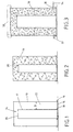
- Figur 3:
- die Anordnung nach Figur 2, bei der der Raum zwischen Außen- und Innenrohr etwa hälftig zusätzlich mit einer Zementsuspension ausgefüllt ist,
- Figur 4:
- einen fertigen Behälter im Längsschnitt.
- Figure 1:
- an arrangement of steel outer and inner steel pipes before filling a concrete aggregate,
- Figure 2:
- the arrangement according to Figure 1, wherein the space formed between the outer and inner tube is filled with a supplement,
- Figure 3:
- 2 shows the arrangement according to FIG. 2, in which the space between the outer and inner tubes is additionally filled in half with a cement suspension,
- Figure 4:
- a finished container in longitudinal section.
In Figur 1 sind ein Stahl-Außenrohr 10 und ein darin konzentrisch
angeordnetes Stahl-Innenrohr 12 zu erkennen.In Figure 1, a steel
Außenrohr 10 und Innenrohr 12 stehen mit ihrem jweils
unteren Ende auf einem Deckel 14 auf, wobei der Deckel 14
über zwei konzentrische Flansche 16, 18 mit Innengewinde auf
korrespondierende Außengewinde am unteren Ende des Außenrohres
10 und des Innenrohres 12 aufgeschraubt ist.
Das Innenrohr 12 ist kürzer als das Außenrohr 10 und endet
entsprechend mit Abstand zum oberen Rand des Außenrohrs 10.
Das Innenrohr 12 ist am oberen Ende mit einer Stahlplatte 20
verschlossen.The
Entsprechend wird zwischen Außenrohr 10 und Innenrohr 12 ein
Ringspalt 22 konstanter Breite (b) und zwischen der Stahlplatte
20 und dem oberen Ende des Außenrohrs 10 ein Raum 24
ausgebildet.Accordingly, a between the
Im nächsten Arbeitsschritt werden der Ringspalt 22 und der
Raum 24 mit einem Bewehrungskorb 26 aus Stahl ausgefüllt
(Figur 2). Die Bewehrung kann auch vorher an der Innenwand
des Außenrohrs und/oder an der Außenwand des Innenrohrs
befestigt, zum Beispiel angeschweißt sein.In the next step, the
Anschließend wird ein Schwerbeton-Zuschlag in den Ringspalt
22 und den Raum 24 gefüllt, der hier aus 20 Gew.-% Baryt der
Kornfraktion 4/8 mm, aus 30 Gew.-% Baryt der Kornfraktion
8/16 mm und 50 Gew.-% Stahlkugeln mit einem Durchmesser
zwischen 5 und 8 mm in homogener Mischung besteht (Figur 2).Then a heavy concrete aggregate is added to the
Danach schließt sich die Injektion eines Zement/Wasser/Verflüssiger-Gemisches
in den vom Bewehrungskorb 26 und
Zuschlag 28 eingenommenen Raum an (Figur 3).This is followed by the injection of a cement / water / plasticizer mixture
in the from the
Dazu weist das Außenrohr 10 zwei, um 180° zueinander versetzte
Öffnungen 30 auf, in die jeweils ein rohrförmiger
Adapter 32 eingeschraubt ist. Die Öffnungen sind am unteren
Ende des Außenrohres 10 angeordnet.For this purpose, the
An die Adapter 32 wird anschließend eine Förderleitung (schematisch durch den Pfeil 34 dargestellt) angeschlossen. A delivery line is then connected to the adapter 32 (shown schematically by arrow 34) connected.
Über die Förderleitung wird anschließend ein Zement/Wasser/Verflüssiger-Gemisch
in Form einer viskosen Suspension unter
Druck in den Ringspalt 22 eingedüst. Im vorliegenden Fall
besteht die Suspension aus Zement des Typs CEM I 42,5, einem
Wassergehalt von 35 %, bezogen auf den Zement und einem
Anteil von 3 % Verflüssiger (Fließmittel hier: Melaminsulfonat),
bezogen auf den Zementanteil.A cement / water / plasticizer mixture is then fed through the delivery line
in the form of a viscous suspension
Pressure injected into the
Während unmittelbar nach Beginn der Injektion die Zementsuspension
nach unten auf die Innenseite des Deckels 14
gelangt, wird der Ringspalt 22 anschließend nach und nach
von unten nach oben mit der Zementsuspension ausgefüllt, die
dabei die Freiräume (Zwickel) zwischen den Zuschlagteilen
und der Bewehrung ausfüllt.While immediately after the start of the injection the cement suspension
down to the inside of the
In Figur 3 ist ein etwa 50 %-iger Füllungsgrad des Ringspaltes
22 durch die Linie 36 gekennzeichnet.In Figure 3 is an approximately 50% degree of filling of the
Unter ständiger Erhöhung des Injektionsdrucks (bis etwa 15
bar) wird die Zementsuspension anschließend weiter
injiziert, bis der Ringspalt 22 und der darüber angeordnete
Raum 24 vollständig mit der Zementsuspension gefüllt sind.Constantly increasing the injection pressure (up to about 15
bar) the cement suspension then continues
injected until the
Nach dem Abbinden und Aushärten des Zements wird eine Stahlplatte
38 (in Figur 3 gestrichelt dargestellt) auf das obere
Ende des Außenrohres 10 aufgeschweißt.After the cement has set and hardened, a steel plate is made
38 (shown in dashed lines in Figure 3) on the upper
Welded end of the
Danach wird die Anordnung um 180° gedreht (Figur 4). Bei
Bedarf kann der Behälterdeckel 14 anschließend durch einen
anderen Stahldeckel 40 ersetzt werden. The arrangement is then rotated through 180 ° (FIG. 4). at
The
Vorzugsweise werden die Öffnungen 30 am fertigen Behälter
ebenfalls verschlossen.Preferably, the
Die 7-Tage-Druckfestigkeit gemäß DIN 1048, Teil 2 des Schwerbetons beträgt 26 N/mm2, die entsprechende 28-Tage-Druckfestigkeit 46 N/mm2.The 7-day compressive strength according to DIN 1048, part 2 of the heavy concrete is 26 N / mm 2 , the corresponding 28-day compressive strength is 46 N / mm 2 .
Der Elastizitätsmodul des Betons wurde in Anlehnung an DIN 1048 Teil 5 mit 30.000 N/mm2 bestimmt.The modulus of elasticity of the concrete was determined based on DIN 1048 Part 5 with 30,000 N / mm 2 .
Claims (15)
- A method for manufacturing a container for transportation and storage of radioactive material, having the following steps:1.1 an inner tube of metal is placed into an outer tube of metal in such a manner that an annular gap of a constant width is formed between the inner and the outer tubes,1.2 the annular gap is then filled with an aggregate or a mixture of aggregates, the minimum grain size of which is 2 mm and the maximum grain size of which is 20 mm, at least 95% by wt. of the aggregate having a bulk density > 4.2 g/cm3,1.3 afterwards, a suspension of cement, water and liquefier is injected under high pressure into the annular gap through at least one opening at the bottom end of the inner and/or the outer tube until the suspension reaches the upper end of the outer tube in filling the gores existing between the aggregate totally,1.4 the suspension being adjusted in such a manner that the concrete being formed together with the aggregate has a bulk density > 4,100 g/cm3 and the set cement together with the aggregate within the annular gap has a compressive strength of concrete according to DIN 1048, part 2 of > 45 N/mm2 after 28 days.
- The method according to claim 1, wherein a Portland cement of the type CEM I 42.5 or having higher values is used as the cement.
- The method according to claim 1, wherein barite, ferrophosphorus, magnetite, iron, lead, hematite, granulated chill-cast iron as well as other metals or mixtures of the mentioned aggregates are used as the aggregate.
- The method according to claim 3, wherein a mixture of barite, ferrophosphorus, magnetite, hematite or mixtures thereof in combination with steel balls are used as the aggregate.
- The method according to claim 4, wherein a mixture of barite, ferrophosphorus, magnetite, hematite or mixtures thereof having the grain fractions 4/8 mm and 8/16 mm in combination with steel balls having a diameter between 4 and 10 mm are used as the aggregate.
- The method according to claim 4, wherein a mixture of barite, ferrophosphorus, magnetite, hematite or mixtures thereof with a 15 to 25% by wt. portion of a grain fraction 4/8 mm and a 25 to 35% by wt. portion of a grain fraction 8/16 mm in combination with 45 to 55% by wt. of steel balls having a diameter between 4 and 8 mm are used as the aggregate.
- The method according to claim 1, wherein an inner tube being closed at its upper end is used, which is shorter than the outer tube, the space between the upper closed end of the inner tube and the upper edge of the outer tube being also filled with the aggregate and the gores between the aggregate being filled with the suspension.
- The method according to claim 1, wherein the inner tube and the outer tube are closed with a metal cover at their lower ends before the aggregate is filled in.
- The method according to claim 1 or 7, wherein a reinforcement is inserted into the annular gap and/or the space formed between the upper closed end of the inner tube and the open end of the outer tube before the aggregate is filled in.
- The method according to claim 9, wherein a reinforcing cage extending essentially over the entire volume of the annular gap and/or the space is used as the reinforcement.
- The method according to claim 1, wherein the upper, the lower or the upper and lower end of the outer tube is closed sealingly with a metal cover or a metal top after the suspension has set, at least one metal cover or metal top being placed removably onto the outer tube.
- A container for transportation and storage of radioactive material having the following features:12.1 the container consists of an outer tube (10) of metal and an inner tube (12) of metal being disposed therein with the same distance all around, an annular gap (22) having a constant width being formed thereby between the inner and outer tubes (12, 10),12.2 the annular gap (22) between the inner and outer tubes (12, 10) is filled with a heavy concrete consisting of an aggregate or a mixture of aggregates (28) having a bulk density > 4.2 g/cm3 and a cement filling the gores between the aggregate, the heavy concrete having a bulk density of > 4,100 g/cm3 and a compressive strength after 28 days according to DIN 1048, part 2 of > 45 N/mm2,12.3 the outer tube (10) and the inner tube (12) are closed at the ends with a metal bottom (38) and a metal cover (14), at least the metal cover (14) being disposed removably.
- The container according to claim 12, wherein the inner tube (12) ends at a distance from the lower end of the outer tube (10), is closed at this end, and a plate of heavy concrete exists between the closed lower end of the inner tube (12) and the lower end of the outer tube (10), which is continuous in material with the heavy concrete in the annular gap.
- The container according to claim 12 or 13, wherein the heavy concrete is reinforced.
- .The container according to claim 14, wherein the reinforcement consists of a reinforcing cage (26).
Applications Claiming Priority (3)
| Application Number | Priority Date | Filing Date | Title |
|---|---|---|---|
| DE19725922A DE19725922C2 (en) | 1997-06-19 | 1997-06-19 | Process for manufacturing a container |
| DE19725922 | 1997-06-19 | ||
| PCT/DE1998/001608 WO1998059346A1 (en) | 1997-06-19 | 1998-06-09 | Container and method for producing a container |
Publications (2)
| Publication Number | Publication Date |
|---|---|
| EP0990237A1 EP0990237A1 (en) | 2000-04-05 |
| EP0990237B1 true EP0990237B1 (en) | 2002-08-07 |
Family
ID=7832941
Family Applications (1)
| Application Number | Title | Priority Date | Filing Date |
|---|---|---|---|
| EP98936155A Expired - Lifetime EP0990237B1 (en) | 1997-06-19 | 1998-06-09 | Container and method for producing a container |
Country Status (15)
| Country | Link |
|---|---|
| US (1) | US6518585B1 (en) |
| EP (1) | EP0990237B1 (en) |
| JP (1) | JP2001508874A (en) |
| KR (1) | KR100320969B1 (en) |
| CN (1) | CN1165915C (en) |
| AU (1) | AU8531398A (en) |
| CA (1) | CA2292589C (en) |
| CZ (1) | CZ293385B6 (en) |
| DE (2) | DE19725922C2 (en) |
| EA (1) | EA001461B1 (en) |
| ES (1) | ES2181250T3 (en) |
| SK (1) | SK283640B6 (en) |
| TW (1) | TW366501B (en) |
| UA (1) | UA54529C2 (en) |
| WO (1) | WO1998059346A1 (en) |
Families Citing this family (12)
| Publication number | Priority date | Publication date | Assignee | Title |
|---|---|---|---|---|
| EP1103984B1 (en) * | 1999-06-19 | 2002-09-18 | GNB Gesellschaft für Nuklear-Behälter mbH | Container for shipping and/or storing radioactive heat releasing parts |
| DE59903429D1 (en) * | 1999-12-15 | 2002-12-19 | Gnb Gmbh | Process for producing a transport and / or storage container for radioactive objects |
| US7014059B2 (en) * | 2002-05-17 | 2006-03-21 | Master Lite Security Products, Inc. | Explosion resistant waste container |
| SE525468C2 (en) * | 2002-11-29 | 2005-03-01 | Oyster Internat Nv C O H B Man | Container device for storing hazardous materials, in particular for final storage of nuclear fuel, and methods for its preparation |
| DE10327466B4 (en) * | 2003-01-13 | 2008-08-07 | Jan Forster | Structure for radiation protection structures |
| JP2006038465A (en) * | 2004-07-22 | 2006-02-09 | Kumagai Gumi Co Ltd | Concrete composition for shielding radiation |
| US9443625B2 (en) * | 2005-03-25 | 2016-09-13 | Holtec International, Inc. | Method of storing high level radioactive waste |
| ES2296522B1 (en) * | 2006-05-26 | 2009-04-01 | Europea De Minerales Y Derivados, S.L. | HEAVY MASS FOR THE MANUFACTURE OF PRODUCTS WITH HIGH CAPACITY OF RADIO-PROTECTION. |
| JP5545788B1 (en) * | 2013-07-07 | 2014-07-09 | 株式会社安藤・間 | Radiation shielding container, radiation shielding box, and method for containing radioactive waste |
| CN108122650A (en) * | 2016-11-29 | 2018-06-05 | 黄璜 | The special-shaped bushing pipe of change can be fitted |
| US20220367078A1 (en) * | 2021-05-17 | 2022-11-17 | Holtec International | Stackable nuclear waste storage system |
| DE102022202475A1 (en) | 2022-03-11 | 2023-09-14 | Fraunhofer-Gesellschaft zur Förderung der angewandten Forschung eingetragener Verein | Multi-layer material composite, component comprising the multi-layer material composite, method for their production and their use |
Family Cites Families (15)
| Publication number | Priority date | Publication date | Assignee | Title |
|---|---|---|---|---|
| US3742985A (en) * | 1967-01-31 | 1973-07-03 | Chemstress Ind Inc | Reinforced pipe |
| DE2817193A1 (en) * | 1978-04-20 | 1979-10-31 | Transnuklear Gmbh | Transport casket for irradiated fuel elements - with webs in concrete filling between inner and outer metal shell |
| FR2516292A1 (en) * | 1981-11-10 | 1983-05-13 | Stockage Assainissement | SPECIAL INJECTION SLIDE AND ITS USE FOR THE STORAGE IN THE SOIL OF RADIOACTIVE WASTE |
| DE3331892C2 (en) * | 1983-09-03 | 1986-01-23 | Kernforschungsanlage Jülich GmbH, 5170 Jülich | Transport and storage containers for radioactive material |
| DE3635500A1 (en) * | 1986-10-18 | 1988-05-11 | Kernforschungsanlage Juelich | HEAVY CONCRETE FOR THE PRODUCTION OF A CONTAINER FOR RADIOACTIVE MATERIAL |
| DE3709315C2 (en) * | 1987-03-21 | 1996-04-25 | Nuklear Service Gmbh Gns | Process for the storage of radioactive waste |
| US5008045A (en) * | 1989-03-23 | 1991-04-16 | Alternative Technologies For Waste, Inc. | Method and apparatus for centrifugally casting hazardous waste |
| US5063967A (en) * | 1989-12-06 | 1991-11-12 | Stephens Patrick J | Pumpable cement grout |
| JP3084123B2 (en) * | 1992-04-15 | 2000-09-04 | ジオスター株式会社 | Box culvert manufacturing method |
| US5457263A (en) * | 1994-02-14 | 1995-10-10 | University Of New Mexico | Method for containing radioactive waste |
| JP3332687B2 (en) * | 1995-10-03 | 2002-10-07 | 株式会社東芝 | Reactor containment vessel |
| JP3020050B2 (en) * | 1995-12-20 | 2000-03-15 | 五洋建設株式会社 | Concrete filling method |
| US5819186A (en) * | 1996-04-26 | 1998-10-06 | Stephens; Patrick J. | Cellular grout radiation barrier |
| US6299950B1 (en) * | 1997-09-30 | 2001-10-09 | Bwxt Y12 Llc | Fireproof impact limiter aggregate packaging inside shipping containers |
| US5949084A (en) * | 1998-06-30 | 1999-09-07 | Schwartz; Martin W. | Radioactive material storage vessel |
-
1997
- 1997-06-19 DE DE19725922A patent/DE19725922C2/en not_active Expired - Fee Related
-
1998
- 1998-06-09 JP JP50355399A patent/JP2001508874A/en active Pending
- 1998-06-09 ES ES98936155T patent/ES2181250T3/en not_active Expired - Lifetime
- 1998-06-09 DE DE59805117T patent/DE59805117D1/en not_active Expired - Lifetime
- 1998-06-09 CA CA002292589A patent/CA2292589C/en not_active Expired - Lifetime
- 1998-06-09 EP EP98936155A patent/EP0990237B1/en not_active Expired - Lifetime
- 1998-06-09 AU AU85313/98A patent/AU8531398A/en not_active Abandoned
- 1998-06-09 US US09/446,502 patent/US6518585B1/en not_active Expired - Fee Related
- 1998-06-09 CZ CZ19994338A patent/CZ293385B6/en not_active IP Right Cessation
- 1998-06-09 SK SK1751-99A patent/SK283640B6/en not_active IP Right Cessation
- 1998-06-09 WO PCT/DE1998/001608 patent/WO1998059346A1/en active IP Right Grant
- 1998-06-09 CN CNB988064073A patent/CN1165915C/en not_active Expired - Fee Related
- 1998-06-09 EA EA199901064A patent/EA001461B1/en not_active IP Right Cessation
- 1998-06-11 TW TW087109302A patent/TW366501B/en not_active IP Right Cessation
- 1998-06-19 KR KR1019980023036A patent/KR100320969B1/en not_active IP Right Cessation
- 1998-09-06 UA UA2000010320A patent/UA54529C2/en unknown
Also Published As
| Publication number | Publication date |
|---|---|
| EA199901064A1 (en) | 2000-08-28 |
| EA001461B1 (en) | 2001-04-23 |
| WO1998059346A1 (en) | 1998-12-30 |
| DE19725922A1 (en) | 1998-12-24 |
| ES2181250T3 (en) | 2003-02-16 |
| UA54529C2 (en) | 2003-03-17 |
| CZ433899A3 (en) | 2000-04-12 |
| SK175199A3 (en) | 2000-06-12 |
| TW366501B (en) | 1999-08-11 |
| SK283640B6 (en) | 2003-11-04 |
| CZ293385B6 (en) | 2004-04-14 |
| KR19990007116A (en) | 1999-01-25 |
| DE19725922C2 (en) | 2000-07-20 |
| JP2001508874A (en) | 2001-07-03 |
| CA2292589A1 (en) | 1998-12-30 |
| EP0990237A1 (en) | 2000-04-05 |
| DE59805117D1 (en) | 2002-09-12 |
| CN1261456A (en) | 2000-07-26 |
| CN1165915C (en) | 2004-09-08 |
| AU8531398A (en) | 1999-01-04 |
| CA2292589C (en) | 2003-02-25 |
| KR100320969B1 (en) | 2002-05-13 |
| US6518585B1 (en) | 2003-02-11 |
Similar Documents
| Publication | Publication Date | Title |
|---|---|---|
| EP0990237B1 (en) | Container and method for producing a container | |
| DE69706926T2 (en) | Containers for radioactive materials and radiation shielding | |
| DE19725922C9 (en) | Method of making a container | |
| WO2000010935A2 (en) | Radiation protective concrete and radiation protective casing | |
| DE102007044846A1 (en) | Transportable tank and tank container for the transport of liquefied gas | |
| DE1810663A1 (en) | Prestressed concrete pressure vessel | |
| CH718234B1 (en) | Prestressed circular tension belt support system and method for controlling deformation of the prestressed circular tension belt support system. | |
| EP0264521B1 (en) | Double-walled transport container for radioactive material | |
| DE69303539T2 (en) | Constipation material, its manufacturing process and the storage of this material in a container store | |
| DE2225664A1 (en) | Underground storage system - for radioactive or poisonous waste prods in liq or free flowing solid form | |
| DE19708899C2 (en) | Process for transporting and storing spent fuel elements and neutron absorbers for carrying out the process | |
| EP0250573B1 (en) | A tension-resisting concrete consisting of cement, aggregate and water | |
| DE2648477C3 (en) | Composite support for mining shafts | |
| DE2049981A1 (en) | Shutdown rod for nuclear reactors with a bed of preferably spherical smoke elements | |
| DE3227512A1 (en) | Consumable shielding container for radioactive waste | |
| Hu | Taiwans Katastrophenschutz und dessen Anpassung im Zuge des Klimawandels. | |
| DE19757843C1 (en) | Storage containers for the intermediate and / or final storage of spent fuel elements | |
| CH691691A5 (en) | Support with reinforcement bars arranged in concrete has complete cross-sectional surface of reinforcement bars amounting to at least 12 per cent of cross-sectional surface of support | |
| DE3326585A1 (en) | Rotationally symmetrical containment | |
| DE2641352C2 (en) | Radial burst protection for pressure vessels, especially for nuclear reactor pressure vessels | |
| DE1299112B (en) | High pressure tank made of reinforced concrete | |
| DE1471517C3 (en) | Process for the production of a frost-resistant injection mortar | |
| DE19606089A1 (en) | Boiling-water reactor safety vessel from steel reinforced concrete | |
| Kucherer | Device to absorb solid radioactive waste suspended in water | |
| DE3429010A1 (en) | Process and equipment for producing building elements used, for example, as dams parallel to a roadway, in underground operation |
Legal Events
| Date | Code | Title | Description |
|---|---|---|---|
| PUAI | Public reference made under article 153(3) epc to a published international application that has entered the european phase |
Free format text: ORIGINAL CODE: 0009012 |
|
| 17P | Request for examination filed |
Effective date: 19991106 |
|
| AK | Designated contracting states |
Kind code of ref document: A1 Designated state(s): BE CH DE ES FR GB IT LI NL |
|
| AX | Request for extension of the european patent |
Free format text: LT PAYMENT 19991106 |
|
| GRAG | Despatch of communication of intention to grant |
Free format text: ORIGINAL CODE: EPIDOS AGRA |
|
| 17Q | First examination report despatched |
Effective date: 20010629 |
|
| RAP1 | Party data changed (applicant data changed or rights of an application transferred) |
Owner name: GNB GESELLSCHAFT FUER NUKLEARBEHAELTER MBH |
|
| RAP3 | Party data changed (applicant data changed or rights of an application transferred) |
Owner name: GNB GESELLSCHAFT FUER NUKLEAR-BEHAELTER MBH |
|
| GRAG | Despatch of communication of intention to grant |
Free format text: ORIGINAL CODE: EPIDOS AGRA |
|
| GRAH | Despatch of communication of intention to grant a patent |
Free format text: ORIGINAL CODE: EPIDOS IGRA |
|
| GRAH | Despatch of communication of intention to grant a patent |
Free format text: ORIGINAL CODE: EPIDOS IGRA |
|
| GRAA | (expected) grant |
Free format text: ORIGINAL CODE: 0009210 |
|
| AK | Designated contracting states |
Kind code of ref document: B1 Designated state(s): BE CH DE ES FR GB IT LI NL |
|
| AX | Request for extension of the european patent |
Free format text: LT PAYMENT 19991106 |
|
| REG | Reference to a national code |
Ref country code: GB Ref legal event code: FG4D Free format text: NOT ENGLISH |
|
| REG | Reference to a national code |
Ref country code: CH Ref legal event code: EP |
|
| REF | Corresponds to: |
Ref document number: 59805117 Country of ref document: DE Date of ref document: 20020912 |
|
| REG | Reference to a national code |
Ref country code: CH Ref legal event code: NV Representative=s name: HANS RUDOLF GACHNANG PATENTANWALT |
|
| GBT | Gb: translation of ep patent filed (gb section 77(6)(a)/1977) |
Effective date: 20021025 |
|
| REG | Reference to a national code |
Ref country code: ES Ref legal event code: FG2A Ref document number: 2181250 Country of ref document: ES Kind code of ref document: T3 |
|
| ET | Fr: translation filed | ||
| PLBE | No opposition filed within time limit |
Free format text: ORIGINAL CODE: 0009261 |
|
| STAA | Information on the status of an ep patent application or granted ep patent |
Free format text: STATUS: NO OPPOSITION FILED WITHIN TIME LIMIT |
|
| 26N | No opposition filed |
Effective date: 20030508 |
|
| PGFP | Annual fee paid to national office [announced via postgrant information from national office to epo] |
Ref country code: GB Payment date: 20040527 Year of fee payment: 7 |
|
| PGFP | Annual fee paid to national office [announced via postgrant information from national office to epo] |
Ref country code: NL Payment date: 20040617 Year of fee payment: 7 |
|
| PGFP | Annual fee paid to national office [announced via postgrant information from national office to epo] |
Ref country code: BE Payment date: 20040623 Year of fee payment: 7 |
|
| PG25 | Lapsed in a contracting state [announced via postgrant information from national office to epo] |
Ref country code: GB Free format text: LAPSE BECAUSE OF NON-PAYMENT OF DUE FEES Effective date: 20050609 |
|
| PG25 | Lapsed in a contracting state [announced via postgrant information from national office to epo] |
Ref country code: BE Free format text: LAPSE BECAUSE OF NON-PAYMENT OF DUE FEES Effective date: 20050630 |
|
| REG | Reference to a national code |
Ref country code: CH Ref legal event code: PFA Owner name: GNS GESELLSCHAFT FUER NUKLEAR-SERVICE MBH Free format text: GNB GESELLSCHAFT FUER NUKLEAR-BEHAELTER MBH#HOLLESTRASSE 7A#45127 ESSEN (DE) -TRANSFER TO- GNS GESELLSCHAFT FUER NUKLEAR-SERVICE MBH#HOLLESTRASSE 7A#45127 ESSEN (DE) |
|
| REG | Reference to a national code |
Ref country code: ES Ref legal event code: PC2A |
|
| PG25 | Lapsed in a contracting state [announced via postgrant information from national office to epo] |
Ref country code: NL Free format text: LAPSE BECAUSE OF NON-PAYMENT OF DUE FEES Effective date: 20060101 |
|
| GBPC | Gb: european patent ceased through non-payment of renewal fee |
Effective date: 20050609 |
|
| NLV4 | Nl: lapsed or anulled due to non-payment of the annual fee |
Effective date: 20060101 |
|
| REG | Reference to a national code |
Ref country code: FR Ref legal event code: TP |
|
| BERE | Be: lapsed |
Owner name: G.- FUR NUKLEAR-BEHALTER M.B.H. *GNB Effective date: 20050630 |
|
| REG | Reference to a national code |
Ref country code: CH Ref legal event code: NV Representative=s name: GACHNANG AG PATENTANWAELTE, CH |
|
| REG | Reference to a national code |
Ref country code: FR Ref legal event code: PLFP Year of fee payment: 19 |
|
| REG | Reference to a national code |
Ref country code: FR Ref legal event code: PLFP Year of fee payment: 20 |
|
| PGFP | Annual fee paid to national office [announced via postgrant information from national office to epo] |
Ref country code: CH Payment date: 20170626 Year of fee payment: 20 Ref country code: DE Payment date: 20170517 Year of fee payment: 20 Ref country code: FR Payment date: 20170621 Year of fee payment: 20 |
|
| PGFP | Annual fee paid to national office [announced via postgrant information from national office to epo] |
Ref country code: IT Payment date: 20170622 Year of fee payment: 20 |
|
| PGFP | Annual fee paid to national office [announced via postgrant information from national office to epo] |
Ref country code: ES Payment date: 20170703 Year of fee payment: 20 |
|
| REG | Reference to a national code |
Ref country code: DE Ref legal event code: R071 Ref document number: 59805117 Country of ref document: DE |
|
| REG | Reference to a national code |
Ref country code: CH Ref legal event code: PL |
|
| REG | Reference to a national code |
Ref country code: ES Ref legal event code: FD2A Effective date: 20200805 |
|
| PG25 | Lapsed in a contracting state [announced via postgrant information from national office to epo] |
Ref country code: ES Free format text: LAPSE BECAUSE OF EXPIRATION OF PROTECTION Effective date: 20180610 |