EP0989904B1 - Module membranaire a membranes en fibres creuses enrobees d'un cote - Google Patents
Module membranaire a membranes en fibres creuses enrobees d'un cote Download PDFInfo
- Publication number
- EP0989904B1 EP0989904B1 EP98928340A EP98928340A EP0989904B1 EP 0989904 B1 EP0989904 B1 EP 0989904B1 EP 98928340 A EP98928340 A EP 98928340A EP 98928340 A EP98928340 A EP 98928340A EP 0989904 B1 EP0989904 B1 EP 0989904B1
- Authority
- EP
- European Patent Office
- Prior art keywords
- fiber membranes
- hollow fiber
- hollow
- membrane
- fluid
- Prior art date
- Legal status (The legal status is an assumption and is not a legal conclusion. Google has not performed a legal analysis and makes no representation as to the accuracy of the status listed.)
- Expired - Lifetime
Links
- 239000012528 membrane Substances 0.000 title claims abstract description 484
- 239000012510 hollow fiber Substances 0.000 title claims abstract description 299
- 239000012530 fluid Substances 0.000 claims abstract description 115
- 239000000126 substance Substances 0.000 claims abstract description 93
- 239000012466 permeate Substances 0.000 claims abstract description 74
- 238000000034 method Methods 0.000 claims abstract description 50
- 150000001875 compounds Chemical class 0.000 claims abstract description 47
- 238000011282 treatment Methods 0.000 claims description 67
- 239000013076 target substance Substances 0.000 claims description 28
- 230000008569 process Effects 0.000 claims description 27
- 238000009826 distribution Methods 0.000 claims description 22
- 239000007788 liquid Substances 0.000 claims description 20
- 238000007789 sealing Methods 0.000 claims description 19
- 239000000725 suspension Substances 0.000 claims description 19
- 239000003446 ligand Substances 0.000 claims description 17
- 125000006850 spacer group Chemical group 0.000 claims description 17
- 239000000203 mixture Substances 0.000 claims description 9
- 238000000926 separation method Methods 0.000 claims description 9
- -1 polypropylene Polymers 0.000 claims description 8
- 238000004140 cleaning Methods 0.000 claims description 7
- 239000003054 catalyst Substances 0.000 claims description 6
- 230000003197 catalytic effect Effects 0.000 claims description 6
- 230000004048 modification Effects 0.000 claims description 6
- 238000012986 modification Methods 0.000 claims description 6
- 229920002678 cellulose Polymers 0.000 claims description 5
- 229920001577 copolymer Polymers 0.000 claims description 4
- 125000000524 functional group Chemical group 0.000 claims description 4
- 239000002033 PVDF binder Substances 0.000 claims description 3
- 239000001913 cellulose Substances 0.000 claims description 3
- 229920001343 polytetrafluoroethylene Polymers 0.000 claims description 3
- 239000004810 polytetrafluoroethylene Substances 0.000 claims description 3
- 229920002981 polyvinylidene fluoride Polymers 0.000 claims description 3
- 239000004952 Polyamide Substances 0.000 claims description 2
- 239000004743 Polypropylene Substances 0.000 claims description 2
- 238000006555 catalytic reaction Methods 0.000 claims description 2
- 229920002492 poly(sulfone) Polymers 0.000 claims description 2
- 229920002647 polyamide Polymers 0.000 claims description 2
- 229920001155 polypropylene Polymers 0.000 claims description 2
- 238000004891 communication Methods 0.000 claims 5
- 230000004907 flux Effects 0.000 abstract 8
- 239000011148 porous material Substances 0.000 description 43
- 229920005862 polyol Polymers 0.000 description 26
- 150000003077 polyols Chemical class 0.000 description 26
- 238000004382 potting Methods 0.000 description 24
- 239000002245 particle Substances 0.000 description 20
- 229920000642 polymer Polymers 0.000 description 14
- 210000002381 plasma Anatomy 0.000 description 12
- 230000036961 partial effect Effects 0.000 description 11
- 230000032258 transport Effects 0.000 description 9
- 239000000463 material Substances 0.000 description 8
- 210000004369 blood Anatomy 0.000 description 7
- 239000008280 blood Substances 0.000 description 7
- 238000005266 casting Methods 0.000 description 7
- 238000010828 elution Methods 0.000 description 6
- 230000006870 function Effects 0.000 description 6
- 238000004587 chromatography analysis Methods 0.000 description 5
- 230000003993 interaction Effects 0.000 description 5
- 230000002829 reductive effect Effects 0.000 description 5
- 239000004753 textile Substances 0.000 description 5
- 238000004804 winding Methods 0.000 description 5
- 108090000790 Enzymes Proteins 0.000 description 4
- 102000004190 Enzymes Human genes 0.000 description 4
- 238000001042 affinity chromatography Methods 0.000 description 4
- 210000004027 cell Anatomy 0.000 description 4
- 230000000694 effects Effects 0.000 description 4
- 239000004744 fabric Substances 0.000 description 4
- 238000001914 filtration Methods 0.000 description 4
- 238000004519 manufacturing process Methods 0.000 description 4
- 238000001179 sorption measurement Methods 0.000 description 4
- 229920002684 Sepharose Polymers 0.000 description 3
- KGNDCEVUMONOKF-UGPLYTSKSA-N benzyl n-[(2r)-1-[(2s,4r)-2-[[(2s)-6-amino-1-(1,3-benzoxazol-2-yl)-1,1-dihydroxyhexan-2-yl]carbamoyl]-4-[(4-methylphenyl)methoxy]pyrrolidin-1-yl]-1-oxo-4-phenylbutan-2-yl]carbamate Chemical compound C1=CC(C)=CC=C1CO[C@H]1CN(C(=O)[C@@H](CCC=2C=CC=CC=2)NC(=O)OCC=2C=CC=CC=2)[C@H](C(=O)N[C@@H](CCCCN)C(O)(O)C=2OC3=CC=CC=C3N=2)C1 KGNDCEVUMONOKF-UGPLYTSKSA-N 0.000 description 3
- 239000012876 carrier material Substances 0.000 description 3
- 235000010980 cellulose Nutrition 0.000 description 3
- 229940125833 compound 23 Drugs 0.000 description 3
- 238000013461 design Methods 0.000 description 3
- 238000005516 engineering process Methods 0.000 description 3
- 230000002255 enzymatic effect Effects 0.000 description 3
- 238000000605 extraction Methods 0.000 description 3
- 239000007789 gas Substances 0.000 description 3
- 108090000623 proteins and genes Proteins 0.000 description 3
- 239000012465 retentate Substances 0.000 description 3
- 239000000243 solution Substances 0.000 description 3
- 238000009941 weaving Methods 0.000 description 3
- PXFBZOLANLWPMH-UHFFFAOYSA-N 16-Epiaffinine Natural products C1C(C2=CC=CC=C2N2)=C2C(=O)CC2C(=CC)CN(C)C1C2CO PXFBZOLANLWPMH-UHFFFAOYSA-N 0.000 description 2
- 229920002307 Dextran Polymers 0.000 description 2
- RTZKZFJDLAIYFH-UHFFFAOYSA-N Diethyl ether Chemical compound CCOCC RTZKZFJDLAIYFH-UHFFFAOYSA-N 0.000 description 2
- 229910004298 SiO 2 Inorganic materials 0.000 description 2
- MZVQCMJNVPIDEA-UHFFFAOYSA-N [CH2]CN(CC)CC Chemical group [CH2]CN(CC)CC MZVQCMJNVPIDEA-UHFFFAOYSA-N 0.000 description 2
- 230000006978 adaptation Effects 0.000 description 2
- 230000008901 benefit Effects 0.000 description 2
- 230000002210 biocatalytic effect Effects 0.000 description 2
- 230000008859 change Effects 0.000 description 2
- 238000009792 diffusion process Methods 0.000 description 2
- 238000007599 discharging Methods 0.000 description 2
- 238000006911 enzymatic reaction Methods 0.000 description 2
- 238000002474 experimental method Methods 0.000 description 2
- 238000009434 installation Methods 0.000 description 2
- 238000009940 knitting Methods 0.000 description 2
- 238000011068 loading method Methods 0.000 description 2
- 239000011159 matrix material Substances 0.000 description 2
- 239000002184 metal Substances 0.000 description 2
- 229910052751 metal Inorganic materials 0.000 description 2
- 238000002156 mixing Methods 0.000 description 2
- 239000004745 nonwoven fabric Substances 0.000 description 2
- 229920006393 polyether sulfone Polymers 0.000 description 2
- 229920002959 polymer blend Polymers 0.000 description 2
- 229920002635 polyurethane Polymers 0.000 description 2
- 239000004814 polyurethane Substances 0.000 description 2
- 229920002451 polyvinyl alcohol Polymers 0.000 description 2
- 235000019422 polyvinyl alcohol Nutrition 0.000 description 2
- 102000004169 proteins and genes Human genes 0.000 description 2
- 238000000746 purification Methods 0.000 description 2
- 230000000717 retained effect Effects 0.000 description 2
- 230000002441 reversible effect Effects 0.000 description 2
- YSUIQYOGTINQIN-UZFYAQMZSA-N 2-amino-9-[(1S,6R,8R,9S,10R,15R,17R,18R)-8-(6-aminopurin-9-yl)-9,18-difluoro-3,12-dihydroxy-3,12-bis(sulfanylidene)-2,4,7,11,13,16-hexaoxa-3lambda5,12lambda5-diphosphatricyclo[13.2.1.06,10]octadecan-17-yl]-1H-purin-6-one Chemical compound NC1=NC2=C(N=CN2[C@@H]2O[C@@H]3COP(S)(=O)O[C@@H]4[C@@H](COP(S)(=O)O[C@@H]2[C@@H]3F)O[C@H]([C@H]4F)N2C=NC3=C2N=CN=C3N)C(=O)N1 YSUIQYOGTINQIN-UZFYAQMZSA-N 0.000 description 1
- HBAQYPYDRFILMT-UHFFFAOYSA-N 8-[3-(1-cyclopropylpyrazol-4-yl)-1H-pyrazolo[4,3-d]pyrimidin-5-yl]-3-methyl-3,8-diazabicyclo[3.2.1]octan-2-one Chemical class C1(CC1)N1N=CC(=C1)C1=NNC2=C1N=C(N=C2)N1C2C(N(CC1CC2)C)=O HBAQYPYDRFILMT-UHFFFAOYSA-N 0.000 description 1
- 239000004953 Aliphatic polyamide Substances 0.000 description 1
- 238000004438 BET method Methods 0.000 description 1
- LSNNMFCWUKXFEE-UHFFFAOYSA-M Bisulfite Chemical compound OS([O-])=O LSNNMFCWUKXFEE-UHFFFAOYSA-M 0.000 description 1
- 102000015081 Blood Coagulation Factors Human genes 0.000 description 1
- 108010039209 Blood Coagulation Factors Proteins 0.000 description 1
- OKTJSMMVPCPJKN-UHFFFAOYSA-N Carbon Chemical compound [C] OKTJSMMVPCPJKN-UHFFFAOYSA-N 0.000 description 1
- 108010093096 Immobilized Enzymes Proteins 0.000 description 1
- 108060003951 Immunoglobulin Proteins 0.000 description 1
- 239000004367 Lipase Substances 0.000 description 1
- 102000004882 Lipase Human genes 0.000 description 1
- 108090001060 Lipase Proteins 0.000 description 1
- 102000018697 Membrane Proteins Human genes 0.000 description 1
- 108010052285 Membrane Proteins Proteins 0.000 description 1
- 102000035195 Peptidases Human genes 0.000 description 1
- 108091005804 Peptidases Proteins 0.000 description 1
- 229920003171 Poly (ethylene oxide) Polymers 0.000 description 1
- 239000004695 Polyether sulfone Substances 0.000 description 1
- 239000002202 Polyethylene glycol Substances 0.000 description 1
- 239000004642 Polyimide Substances 0.000 description 1
- 239000004721 Polyphenylene oxide Substances 0.000 description 1
- 239000004372 Polyvinyl alcohol Substances 0.000 description 1
- 239000004365 Protease Substances 0.000 description 1
- 241000700605 Viruses Species 0.000 description 1
- 239000013543 active substance Substances 0.000 description 1
- 239000000853 adhesive Substances 0.000 description 1
- 230000001070 adhesive effect Effects 0.000 description 1
- 230000000274 adsorptive effect Effects 0.000 description 1
- 125000001931 aliphatic group Chemical group 0.000 description 1
- 229920003231 aliphatic polyamide Polymers 0.000 description 1
- 238000005349 anion exchange Methods 0.000 description 1
- 239000004760 aramid Substances 0.000 description 1
- 229920003235 aromatic polyamide Polymers 0.000 description 1
- 230000009286 beneficial effect Effects 0.000 description 1
- 239000011942 biocatalyst Substances 0.000 description 1
- 230000015572 biosynthetic process Effects 0.000 description 1
- 239000003114 blood coagulation factor Substances 0.000 description 1
- 229910052799 carbon Inorganic materials 0.000 description 1
- 238000005341 cation exchange Methods 0.000 description 1
- 150000001768 cations Chemical class 0.000 description 1
- 239000006285 cell suspension Substances 0.000 description 1
- 229920003086 cellulose ether Polymers 0.000 description 1
- 239000000919 ceramic Substances 0.000 description 1
- 239000013522 chelant Substances 0.000 description 1
- 230000000052 comparative effect Effects 0.000 description 1
- 230000006835 compression Effects 0.000 description 1
- 238000007906 compression Methods 0.000 description 1
- 238000010276 construction Methods 0.000 description 1
- 230000008878 coupling Effects 0.000 description 1
- 238000010168 coupling process Methods 0.000 description 1
- 238000005859 coupling reaction Methods 0.000 description 1
- 230000007423 decrease Effects 0.000 description 1
- 238000011161 development Methods 0.000 description 1
- 238000000502 dialysis Methods 0.000 description 1
- 239000003814 drug Substances 0.000 description 1
- 230000002349 favourable effect Effects 0.000 description 1
- 239000000706 filtrate Substances 0.000 description 1
- 238000003958 fumigation Methods 0.000 description 1
- 238000010353 genetic engineering Methods 0.000 description 1
- 239000011521 glass Substances 0.000 description 1
- 239000003102 growth factor Substances 0.000 description 1
- 229940088597 hormone Drugs 0.000 description 1
- 239000005556 hormone Substances 0.000 description 1
- 239000001257 hydrogen Substances 0.000 description 1
- 229910052739 hydrogen Inorganic materials 0.000 description 1
- 230000007062 hydrolysis Effects 0.000 description 1
- 238000006460 hydrolysis reaction Methods 0.000 description 1
- 230000002209 hydrophobic effect Effects 0.000 description 1
- 125000001165 hydrophobic group Chemical group 0.000 description 1
- 238000003703 image analysis method Methods 0.000 description 1
- 230000003100 immobilizing effect Effects 0.000 description 1
- 102000018358 immunoglobulin Human genes 0.000 description 1
- 229940072221 immunoglobulins Drugs 0.000 description 1
- 229910010272 inorganic material Inorganic materials 0.000 description 1
- 239000011147 inorganic material Substances 0.000 description 1
- 238000004255 ion exchange chromatography Methods 0.000 description 1
- 238000002955 isolation Methods 0.000 description 1
- 235000019421 lipase Nutrition 0.000 description 1
- 229920002521 macromolecule Polymers 0.000 description 1
- 238000001471 micro-filtration Methods 0.000 description 1
- 238000002429 nitrogen sorption measurement Methods 0.000 description 1
- 239000003921 oil Substances 0.000 description 1
- 210000000056 organ Anatomy 0.000 description 1
- 229920000620 organic polymer Polymers 0.000 description 1
- 230000035699 permeability Effects 0.000 description 1
- 229920000110 poly(aryl ether sulfone) Polymers 0.000 description 1
- 229920002239 polyacrylonitrile Polymers 0.000 description 1
- 229920002480 polybenzimidazole Polymers 0.000 description 1
- 229920001610 polycaprolactone Polymers 0.000 description 1
- 239000004632 polycaprolactone Substances 0.000 description 1
- 229920001601 polyetherimide Polymers 0.000 description 1
- 229920001223 polyethylene glycol Polymers 0.000 description 1
- 229920001721 polyimide Polymers 0.000 description 1
- 239000002861 polymer material Substances 0.000 description 1
- 229920006380 polyphenylene oxide Polymers 0.000 description 1
- 229920000915 polyvinyl chloride Polymers 0.000 description 1
- 239000004800 polyvinyl chloride Substances 0.000 description 1
- 229920000036 polyvinylpyrrolidone Polymers 0.000 description 1
- 239000001267 polyvinylpyrrolidone Substances 0.000 description 1
- 235000013855 polyvinylpyrrolidone Nutrition 0.000 description 1
- 239000012460 protein solution Substances 0.000 description 1
- 239000002510 pyrogen Substances 0.000 description 1
- 230000009467 reduction Effects 0.000 description 1
- 239000004627 regenerated cellulose Substances 0.000 description 1
- 230000006641 stabilisation Effects 0.000 description 1
- 238000011105 stabilization Methods 0.000 description 1
- 229920001059 synthetic polymer Polymers 0.000 description 1
- 230000001225 therapeutic effect Effects 0.000 description 1
- 230000007704 transition Effects 0.000 description 1
- 238000000108 ultra-filtration Methods 0.000 description 1
- 238000009827 uniform distribution Methods 0.000 description 1
- 238000011144 upstream manufacturing Methods 0.000 description 1
Images


Classifications
-
- B—PERFORMING OPERATIONS; TRANSPORTING
- B01—PHYSICAL OR CHEMICAL PROCESSES OR APPARATUS IN GENERAL
- B01J—CHEMICAL OR PHYSICAL PROCESSES, e.g. CATALYSIS OR COLLOID CHEMISTRY; THEIR RELEVANT APPARATUS
- B01J20/00—Solid sorbent compositions or filter aid compositions; Sorbents for chromatography; Processes for preparing, regenerating or reactivating thereof
- B01J20/28—Solid sorbent compositions or filter aid compositions; Sorbents for chromatography; Processes for preparing, regenerating or reactivating thereof characterised by their form or physical properties
- B01J20/28014—Solid sorbent compositions or filter aid compositions; Sorbents for chromatography; Processes for preparing, regenerating or reactivating thereof characterised by their form or physical properties characterised by their form
- B01J20/28033—Membrane, sheet, cloth, pad, lamellar or mat
-
- B—PERFORMING OPERATIONS; TRANSPORTING
- B01—PHYSICAL OR CHEMICAL PROCESSES OR APPARATUS IN GENERAL
- B01D—SEPARATION
- B01D15/00—Separating processes involving the treatment of liquids with solid sorbents; Apparatus therefor
- B01D15/08—Selective adsorption, e.g. chromatography
-
- B—PERFORMING OPERATIONS; TRANSPORTING
- B01—PHYSICAL OR CHEMICAL PROCESSES OR APPARATUS IN GENERAL
- B01D—SEPARATION
- B01D53/00—Separation of gases or vapours; Recovering vapours of volatile solvents from gases; Chemical or biological purification of waste gases, e.g. engine exhaust gases, smoke, fumes, flue gases, aerosols
- B01D53/22—Separation of gases or vapours; Recovering vapours of volatile solvents from gases; Chemical or biological purification of waste gases, e.g. engine exhaust gases, smoke, fumes, flue gases, aerosols by diffusion
-
- B—PERFORMING OPERATIONS; TRANSPORTING
- B01—PHYSICAL OR CHEMICAL PROCESSES OR APPARATUS IN GENERAL
- B01D—SEPARATION
- B01D61/00—Processes of separation using semi-permeable membranes, e.g. dialysis, osmosis or ultrafiltration; Apparatus, accessories or auxiliary operations specially adapted therefor
- B01D61/007—Separation by stereostructure, steric separation
-
- B—PERFORMING OPERATIONS; TRANSPORTING
- B01—PHYSICAL OR CHEMICAL PROCESSES OR APPARATUS IN GENERAL
- B01D—SEPARATION
- B01D63/00—Apparatus in general for separation processes using semi-permeable membranes
- B01D63/02—Hollow fibre modules
-
- B—PERFORMING OPERATIONS; TRANSPORTING
- B01—PHYSICAL OR CHEMICAL PROCESSES OR APPARATUS IN GENERAL
- B01D—SEPARATION
- B01D63/00—Apparatus in general for separation processes using semi-permeable membranes
- B01D63/02—Hollow fibre modules
- B01D63/024—Hollow fibre modules with a single potted end
-
- B—PERFORMING OPERATIONS; TRANSPORTING
- B01—PHYSICAL OR CHEMICAL PROCESSES OR APPARATUS IN GENERAL
- B01D—SEPARATION
- B01D63/00—Apparatus in general for separation processes using semi-permeable membranes
- B01D63/02—Hollow fibre modules
- B01D63/026—Wafer type modules or flat-surface type modules
-
- B—PERFORMING OPERATIONS; TRANSPORTING
- B01—PHYSICAL OR CHEMICAL PROCESSES OR APPARATUS IN GENERAL
- B01J—CHEMICAL OR PHYSICAL PROCESSES, e.g. CATALYSIS OR COLLOID CHEMISTRY; THEIR RELEVANT APPARATUS
- B01J20/00—Solid sorbent compositions or filter aid compositions; Sorbents for chromatography; Processes for preparing, regenerating or reactivating thereof
- B01J20/28—Solid sorbent compositions or filter aid compositions; Sorbents for chromatography; Processes for preparing, regenerating or reactivating thereof characterised by their form or physical properties
- B01J20/28014—Solid sorbent compositions or filter aid compositions; Sorbents for chromatography; Processes for preparing, regenerating or reactivating thereof characterised by their form or physical properties characterised by their form
- B01J20/28016—Particle form
- B01J20/28021—Hollow particles, e.g. hollow spheres, microspheres or cenospheres
-
- B—PERFORMING OPERATIONS; TRANSPORTING
- B01—PHYSICAL OR CHEMICAL PROCESSES OR APPARATUS IN GENERAL
- B01J—CHEMICAL OR PHYSICAL PROCESSES, e.g. CATALYSIS OR COLLOID CHEMISTRY; THEIR RELEVANT APPARATUS
- B01J20/00—Solid sorbent compositions or filter aid compositions; Sorbents for chromatography; Processes for preparing, regenerating or reactivating thereof
- B01J20/28—Solid sorbent compositions or filter aid compositions; Sorbents for chromatography; Processes for preparing, regenerating or reactivating thereof characterised by their form or physical properties
- B01J20/28014—Solid sorbent compositions or filter aid compositions; Sorbents for chromatography; Processes for preparing, regenerating or reactivating thereof characterised by their form or physical properties characterised by their form
- B01J20/28023—Fibres or filaments
-
- B—PERFORMING OPERATIONS; TRANSPORTING
- B01—PHYSICAL OR CHEMICAL PROCESSES OR APPARATUS IN GENERAL
- B01J—CHEMICAL OR PHYSICAL PROCESSES, e.g. CATALYSIS OR COLLOID CHEMISTRY; THEIR RELEVANT APPARATUS
- B01J20/00—Solid sorbent compositions or filter aid compositions; Sorbents for chromatography; Processes for preparing, regenerating or reactivating thereof
- B01J20/28—Solid sorbent compositions or filter aid compositions; Sorbents for chromatography; Processes for preparing, regenerating or reactivating thereof characterised by their form or physical properties
- B01J20/28014—Solid sorbent compositions or filter aid compositions; Sorbents for chromatography; Processes for preparing, regenerating or reactivating thereof characterised by their form or physical properties characterised by their form
- B01J20/28052—Several layers of identical or different sorbents stacked in a housing, e.g. in a column
-
- B—PERFORMING OPERATIONS; TRANSPORTING
- B01—PHYSICAL OR CHEMICAL PROCESSES OR APPARATUS IN GENERAL
- B01J—CHEMICAL OR PHYSICAL PROCESSES, e.g. CATALYSIS OR COLLOID CHEMISTRY; THEIR RELEVANT APPARATUS
- B01J20/00—Solid sorbent compositions or filter aid compositions; Sorbents for chromatography; Processes for preparing, regenerating or reactivating thereof
- B01J20/28—Solid sorbent compositions or filter aid compositions; Sorbents for chromatography; Processes for preparing, regenerating or reactivating thereof characterised by their form or physical properties
- B01J20/28054—Solid sorbent compositions or filter aid compositions; Sorbents for chromatography; Processes for preparing, regenerating or reactivating thereof characterised by their form or physical properties characterised by their surface properties or porosity
- B01J20/28057—Surface area, e.g. B.E.T specific surface area
-
- B—PERFORMING OPERATIONS; TRANSPORTING
- B01—PHYSICAL OR CHEMICAL PROCESSES OR APPARATUS IN GENERAL
- B01J—CHEMICAL OR PHYSICAL PROCESSES, e.g. CATALYSIS OR COLLOID CHEMISTRY; THEIR RELEVANT APPARATUS
- B01J20/00—Solid sorbent compositions or filter aid compositions; Sorbents for chromatography; Processes for preparing, regenerating or reactivating thereof
- B01J20/30—Processes for preparing, regenerating, or reactivating
- B01J20/32—Impregnating or coating ; Solid sorbent compositions obtained from processes involving impregnating or coating
- B01J20/3202—Impregnating or coating ; Solid sorbent compositions obtained from processes involving impregnating or coating characterised by the carrier, support or substrate used for impregnation or coating
- B01J20/3206—Organic carriers, supports or substrates
- B01J20/3208—Polymeric carriers, supports or substrates
- B01J20/321—Polymeric carriers, supports or substrates consisting of a polymer obtained by reactions involving only carbon to carbon unsaturated bonds
-
- B—PERFORMING OPERATIONS; TRANSPORTING
- B01—PHYSICAL OR CHEMICAL PROCESSES OR APPARATUS IN GENERAL
- B01J—CHEMICAL OR PHYSICAL PROCESSES, e.g. CATALYSIS OR COLLOID CHEMISTRY; THEIR RELEVANT APPARATUS
- B01J20/00—Solid sorbent compositions or filter aid compositions; Sorbents for chromatography; Processes for preparing, regenerating or reactivating thereof
- B01J20/30—Processes for preparing, regenerating, or reactivating
- B01J20/32—Impregnating or coating ; Solid sorbent compositions obtained from processes involving impregnating or coating
- B01J20/3202—Impregnating or coating ; Solid sorbent compositions obtained from processes involving impregnating or coating characterised by the carrier, support or substrate used for impregnation or coating
- B01J20/3206—Organic carriers, supports or substrates
- B01J20/3208—Polymeric carriers, supports or substrates
- B01J20/3212—Polymeric carriers, supports or substrates consisting of a polymer obtained by reactions otherwise than involving only carbon to carbon unsaturated bonds
-
- B—PERFORMING OPERATIONS; TRANSPORTING
- B01—PHYSICAL OR CHEMICAL PROCESSES OR APPARATUS IN GENERAL
- B01J—CHEMICAL OR PHYSICAL PROCESSES, e.g. CATALYSIS OR COLLOID CHEMISTRY; THEIR RELEVANT APPARATUS
- B01J20/00—Solid sorbent compositions or filter aid compositions; Sorbents for chromatography; Processes for preparing, regenerating or reactivating thereof
- B01J20/30—Processes for preparing, regenerating, or reactivating
- B01J20/32—Impregnating or coating ; Solid sorbent compositions obtained from processes involving impregnating or coating
- B01J20/3214—Impregnating or coating ; Solid sorbent compositions obtained from processes involving impregnating or coating characterised by the method for obtaining this coating or impregnating
- B01J20/3217—Resulting in a chemical bond between the coating or impregnating layer and the carrier, support or substrate, e.g. a covalent bond
- B01J20/3219—Resulting in a chemical bond between the coating or impregnating layer and the carrier, support or substrate, e.g. a covalent bond involving a particular spacer or linking group, e.g. for attaching an active group
-
- B—PERFORMING OPERATIONS; TRANSPORTING
- B01—PHYSICAL OR CHEMICAL PROCESSES OR APPARATUS IN GENERAL
- B01J—CHEMICAL OR PHYSICAL PROCESSES, e.g. CATALYSIS OR COLLOID CHEMISTRY; THEIR RELEVANT APPARATUS
- B01J20/00—Solid sorbent compositions or filter aid compositions; Sorbents for chromatography; Processes for preparing, regenerating or reactivating thereof
- B01J20/30—Processes for preparing, regenerating, or reactivating
- B01J20/32—Impregnating or coating ; Solid sorbent compositions obtained from processes involving impregnating or coating
- B01J20/3231—Impregnating or coating ; Solid sorbent compositions obtained from processes involving impregnating or coating characterised by the coating or impregnating layer
- B01J20/3234—Inorganic material layers
- B01J20/3236—Inorganic material layers containing metal, other than zeolites, e.g. oxides, hydroxides, sulphides or salts
-
- B—PERFORMING OPERATIONS; TRANSPORTING
- B01—PHYSICAL OR CHEMICAL PROCESSES OR APPARATUS IN GENERAL
- B01J—CHEMICAL OR PHYSICAL PROCESSES, e.g. CATALYSIS OR COLLOID CHEMISTRY; THEIR RELEVANT APPARATUS
- B01J20/00—Solid sorbent compositions or filter aid compositions; Sorbents for chromatography; Processes for preparing, regenerating or reactivating thereof
- B01J20/30—Processes for preparing, regenerating, or reactivating
- B01J20/32—Impregnating or coating ; Solid sorbent compositions obtained from processes involving impregnating or coating
- B01J20/3231—Impregnating or coating ; Solid sorbent compositions obtained from processes involving impregnating or coating characterised by the coating or impregnating layer
- B01J20/3242—Layers with a functional group, e.g. an affinity material, a ligand, a reactant or a complexing group
- B01J20/3244—Non-macromolecular compounds
- B01J20/3246—Non-macromolecular compounds having a well defined chemical structure
- B01J20/3248—Non-macromolecular compounds having a well defined chemical structure the functional group or the linking, spacer or anchoring group as a whole comprising at least one type of heteroatom selected from a nitrogen, oxygen or sulfur, these atoms not being part of the carrier as such
- B01J20/3251—Non-macromolecular compounds having a well defined chemical structure the functional group or the linking, spacer or anchoring group as a whole comprising at least one type of heteroatom selected from a nitrogen, oxygen or sulfur, these atoms not being part of the carrier as such comprising at least two different types of heteroatoms selected from nitrogen, oxygen or sulphur
-
- B—PERFORMING OPERATIONS; TRANSPORTING
- B01—PHYSICAL OR CHEMICAL PROCESSES OR APPARATUS IN GENERAL
- B01J—CHEMICAL OR PHYSICAL PROCESSES, e.g. CATALYSIS OR COLLOID CHEMISTRY; THEIR RELEVANT APPARATUS
- B01J20/00—Solid sorbent compositions or filter aid compositions; Sorbents for chromatography; Processes for preparing, regenerating or reactivating thereof
- B01J20/30—Processes for preparing, regenerating, or reactivating
- B01J20/32—Impregnating or coating ; Solid sorbent compositions obtained from processes involving impregnating or coating
- B01J20/3231—Impregnating or coating ; Solid sorbent compositions obtained from processes involving impregnating or coating characterised by the coating or impregnating layer
- B01J20/3242—Layers with a functional group, e.g. an affinity material, a ligand, a reactant or a complexing group
- B01J20/3244—Non-macromolecular compounds
- B01J20/3246—Non-macromolecular compounds having a well defined chemical structure
- B01J20/3257—Non-macromolecular compounds having a well defined chemical structure the functional group or the linking, spacer or anchoring group as a whole comprising at least one of the heteroatoms nitrogen, oxygen or sulfur together with at least one silicon atom, these atoms not being part of the carrier as such
- B01J20/3259—Non-macromolecular compounds having a well defined chemical structure the functional group or the linking, spacer or anchoring group as a whole comprising at least one of the heteroatoms nitrogen, oxygen or sulfur together with at least one silicon atom, these atoms not being part of the carrier as such comprising at least two different types of heteroatoms selected from nitrogen, oxygen or sulfur with at least one silicon atom
-
- B—PERFORMING OPERATIONS; TRANSPORTING
- B01—PHYSICAL OR CHEMICAL PROCESSES OR APPARATUS IN GENERAL
- B01J—CHEMICAL OR PHYSICAL PROCESSES, e.g. CATALYSIS OR COLLOID CHEMISTRY; THEIR RELEVANT APPARATUS
- B01J20/00—Solid sorbent compositions or filter aid compositions; Sorbents for chromatography; Processes for preparing, regenerating or reactivating thereof
- B01J20/30—Processes for preparing, regenerating, or reactivating
- B01J20/32—Impregnating or coating ; Solid sorbent compositions obtained from processes involving impregnating or coating
- B01J20/3231—Impregnating or coating ; Solid sorbent compositions obtained from processes involving impregnating or coating characterised by the coating or impregnating layer
- B01J20/3242—Layers with a functional group, e.g. an affinity material, a ligand, a reactant or a complexing group
- B01J20/3244—Non-macromolecular compounds
- B01J20/3246—Non-macromolecular compounds having a well defined chemical structure
- B01J20/3257—Non-macromolecular compounds having a well defined chemical structure the functional group or the linking, spacer or anchoring group as a whole comprising at least one of the heteroatoms nitrogen, oxygen or sulfur together with at least one silicon atom, these atoms not being part of the carrier as such
- B01J20/3261—Non-macromolecular compounds having a well defined chemical structure the functional group or the linking, spacer or anchoring group as a whole comprising at least one of the heteroatoms nitrogen, oxygen or sulfur together with at least one silicon atom, these atoms not being part of the carrier as such comprising a cyclic structure not containing any of the heteroatoms nitrogen, oxygen or sulfur, e.g. aromatic structures
-
- B—PERFORMING OPERATIONS; TRANSPORTING
- B01—PHYSICAL OR CHEMICAL PROCESSES OR APPARATUS IN GENERAL
- B01J—CHEMICAL OR PHYSICAL PROCESSES, e.g. CATALYSIS OR COLLOID CHEMISTRY; THEIR RELEVANT APPARATUS
- B01J20/00—Solid sorbent compositions or filter aid compositions; Sorbents for chromatography; Processes for preparing, regenerating or reactivating thereof
- B01J20/30—Processes for preparing, regenerating, or reactivating
- B01J20/32—Impregnating or coating ; Solid sorbent compositions obtained from processes involving impregnating or coating
- B01J20/3231—Impregnating or coating ; Solid sorbent compositions obtained from processes involving impregnating or coating characterised by the coating or impregnating layer
- B01J20/3242—Layers with a functional group, e.g. an affinity material, a ligand, a reactant or a complexing group
- B01J20/3268—Macromolecular compounds
- B01J20/3272—Polymers obtained by reactions otherwise than involving only carbon to carbon unsaturated bonds
- B01J20/3274—Proteins, nucleic acids, polysaccharides, antibodies or antigens
-
- B01J35/59—
-
- B—PERFORMING OPERATIONS; TRANSPORTING
- B01—PHYSICAL OR CHEMICAL PROCESSES OR APPARATUS IN GENERAL
- B01D—SEPARATION
- B01D15/00—Separating processes involving the treatment of liquids with solid sorbents; Apparatus therefor
- B01D15/08—Selective adsorption, e.g. chromatography
- B01D15/26—Selective adsorption, e.g. chromatography characterised by the separation mechanism
- B01D15/38—Selective adsorption, e.g. chromatography characterised by the separation mechanism involving specific interaction not covered by one or more of groups B01D15/265 - B01D15/36
- B01D15/3804—Affinity chromatography
-
- B—PERFORMING OPERATIONS; TRANSPORTING
- B01—PHYSICAL OR CHEMICAL PROCESSES OR APPARATUS IN GENERAL
- B01D—SEPARATION
- B01D15/00—Separating processes involving the treatment of liquids with solid sorbents; Apparatus therefor
- B01D15/08—Selective adsorption, e.g. chromatography
- B01D15/26—Selective adsorption, e.g. chromatography characterised by the separation mechanism
- B01D15/38—Selective adsorption, e.g. chromatography characterised by the separation mechanism involving specific interaction not covered by one or more of groups B01D15/265 - B01D15/36
- B01D15/3857—Reaction chromatography
-
- B—PERFORMING OPERATIONS; TRANSPORTING
- B01—PHYSICAL OR CHEMICAL PROCESSES OR APPARATUS IN GENERAL
- B01D—SEPARATION
- B01D2313/00—Details relating to membrane modules or apparatus
- B01D2313/14—Specific spacers
-
- B—PERFORMING OPERATIONS; TRANSPORTING
- B01—PHYSICAL OR CHEMICAL PROCESSES OR APPARATUS IN GENERAL
- B01D—SEPARATION
- B01D2313/00—Details relating to membrane modules or apparatus
- B01D2313/42—Catalysts within the flow path
-
- B—PERFORMING OPERATIONS; TRANSPORTING
- B01—PHYSICAL OR CHEMICAL PROCESSES OR APPARATUS IN GENERAL
- B01D—SEPARATION
- B01D2319/00—Membrane assemblies within one housing
- B01D2319/04—Elements in parallel
Definitions
- Substance-specific treatments for fluids are increasing Degree of importance in application areas such as biotechnology, medicine or chemical technology. Under fluids are gases, gas mixtures and generally liquids such as. Protein solutions, pre-filtered suspensions or clear Subsume solutions.
- An example of a substance specific Treatment is the extraction of active substances from cell suspensions, in which genetically modified cells substances such as antibodies, Hormones, growth factors or enzymes in mostly small ones Have produced concentrations.
- An important application is also the extracorporeal removal of unwanted substances from human blood plasma and the extraction of components such as. Immunoglobulins or coagulation factors from donated Blood plasma. After all, it is widely used also catalytic or biocatalytic - enzymatic - treatment of liquids such as the hydrolysis of oils by lipases immobilized on a matrix.
- the substance-specific treatment of fluids is often carried out in such a way that the fluid to be treated is brought into contact with a carrier material on and / or in which interacting groups or substances are immobilized in a specific, selective manner with the target substance contained in the fluid, ie interact with the substance to which the substance-specific treatment is aimed.
- Such interactions can be, for example, cation or anion exchange, hydrophilic-hydrophobic interaction, hydrogen bonding, affinity or enzymatic or catalytic reactions and the like.
- ligands are coupled or immobilized in the support material, which have the function of specifically binding an individual target substance or an entire class of substances by adsorption. This target substance is called a ligate.
- class-specific ligands are positively charged diethylaminoethyl (DEAE) groups or negatively charged sulfonic acid (SO 3 ) groups, which adsorb the class of positively charged or negatively charged molecules.
- Specific ligands are, for example, antibodies against a specific protein which is bound to the antibody as a ligate.
- Essential criteria for the substance-specific treatment of Fluids are productivity and selectivity. With view on Productivity, it is important that as many substance-specific active groups per volume unit are available, with the target substance contained in the fluid to be treated can interact. At the same time is one Maximizing the transport of the target substance to the substance-specific aiming at active groups or substances.
- a carrier material often used in affinity chromatography for ligands are Sepharose particles, which are in the form a bed in a chromatography column. Although a high concentration of ligands with high Allowing selectivity to be achieved is due to productivity the high pressure losses of the particle columns and the compressibility the Sepharose particles are known to be low. Furthermore is the access of the ligates to those in the Sepharose particles contained ligands diffusion-controlled, whereby especially when separating larger molecules such as e.g. of proteins due to low diffusion rates long dwell times and therefore only low throughputs and low Productivities result.
- membranes made of different materials and with different pore structures available, so that a Adaptation to the physicochemical properties of the treatment Fluids and a convective transport of the to be treated Fluids e.g. with a target substance contained in it the membrane is possible.
- membranes stand out due to their usually only small wall thickness (e.g. ⁇ 100 ⁇ m) due to short transport routes of the fluid to be treated e.g. to interacting groups immobilized in the membranes from, which makes the dwell times comparatively short, the Low pressure drops, the linear flow velocities and so that the binding rates are high.
- modules containing such membranes described in procedures for substance-specific treatment of fluids can be used. It is between the so-called dead-end mode or the dead-end modules and cross-flow mode or to distinguish the cross-flow modules.
- the feed stream flows in parallel to one side of the membrane. Part of the Feed streams through the membrane.
- the one who stepped through Partial stream is called permeate, the one remaining on the feedstream side Partial stream derived as retentate. This can also an additional fluid flow on the permeate side of the membrane be introduced, the one that has passed through the membrane Partial stream picks up.
- Dead-end membrane modules based on hollow fiber membranes often for applications in the field of ultra or microfiltration and often e.g. used for fumigation of liquids.
- these membrane modules e.g. in the EP-A-0 138 060 or EP-A-0 659 468 the hollow fiber membranes bent into a U-shape and their ends together embedded in a potting compound and opened.
- the gas or the liquid to be filtered flows, for example, over the open ends in the lumens of the hollow fiber membranes and permeated due to the pressure difference in the outside space around the hollow fiber membranes. In filtration applications remains then the filtered component in the membrane.
- Another version of dead-end membrane modules are the hollow fiber membranes are essentially straight in the housing arranged and with their one, open end together in a potting compound embedded, whereas its second end free, i.e. is not embedded. The end not embedded the hollow fiber membranes are closed in these modules.
- Membrane modules are, for example, in US-A-4 002 567, US-A-4 547 289, EP-A-0 138 060 or EP-A-0 732 142.
- dead-end membrane modules are suitable for the treatment e.g. of suspensions then often not suitable if the size of the particles contained in the suspension are in the order of the pore diameter. The particles would lead to the formation of a layer on the membrane wall and block the membrane.
- Affinity separation process Such dead-end modules can be used for suspensions only in combination with an upstream pre-cleaning stage operate. This loses one However, the process is more efficient, for example in that in many A large part of the target substance is caused by such pre-cleaning get lost.
- WO 90/05018 discloses a cross-flow module with hollow fiber membranes for use in affinity separation processes. With this becomes a liquid containing ligate via an inlet device introduced into the module housing and flows tangentially along one side of the hollow fiber membranes, in and on which the Ligands are coupled. Part of the liquid permeates through the membrane, with the ligates attached to the ligands be deposited, and occurs on the opposite side of the entry side Membrane side as a permeate stream. About separate Outlet devices become retentate stream and permeate stream derived.
- a modification of a cross-flow process is described in WO 93/02777.
- a plasma filter made of U-shaped bends is used from the blood and embedded at their ends in a specially shaped housing Hollow fiber membranes.
- the hollow fiber membranes are on the lumen side with blood flowing, the substance-specific treatment takes place on the blood plasma separated in the membrane External space around the hollow fiber membranes in the housing, in which a Cleaning medium.
- the bundle can be divided into one Inflow branch and divide into an outflow branch. Because of the positive occurring in the area of the inflow branch Transmembrane pressure is a convective transport of blood plasma through the membrane into the outside space. In the area of the outflow branch flows the treated plasma due to the occurring there negative transmembrane pressure in the lumen of the hollow fiber membranes back and is reunited with the blood.
- EP-A-0 341 413 describes an adsorber module for the treatment of Whole blood described, in which the contained in the module, on their both ends embedded in potting compounds and with ligands provided hollow fiber membranes in cross-flow mode on the lumen side are flooded with blood.
- plasma occurs as a permeate through the hollow fiber membrane wall in which the hollow fiber membranes enclosing outside space, the in the membrane wall Treatment of the plasma is carried out.
- this module has no outlet for the permeate, rather the plasma separated as permeate collects in the outside space around the capillaries and occurs as a result of the emerging Pressure conditions again through the hollow fiber membrane wall into the lumen of the hollow fiber membrane. Due to the fact that with such a module concept, the permeate flow through twice must pass through the membrane wall is this permeate stream and thus the portion subjected to the substance-specific treatment of the plasma is relatively small. This also means that the required Treatment times are relatively long.
- the modules described which are operated in cross-flow mode, show various disadvantages. So with separate permeate and Retentate flows additional pumps and / or control organs required. Furthermore, the modules are double-sided Embedding of the hollow fiber membranes at their ends is expensive manufacturing, and it increases due to the embedding shorter module lengths, the proportion of membranes increases to that in terms of substance-specific treatment has no function. Because with cross-flow modules only a partial flow of the total fluid to be treated passed through the membrane a series connection of several modules is often required. Then, however, the effort for manufacturing increases and operation of the cross-flow modules according to the state of the art considerably.
- the task is with a membrane module according to the preamble of Claim 1 solved in that the lumens of the hollow fiber membranes at their second ends are open and into the outside space open, and wherein a large number of functional groups are coupled to the membranes, which interact with the fluid flowing through the membrane to be treated.
- Fluids to be treated are generally those fluids that certain Contain substances or target substances to which the substance-specific treatment.
- the flow of the hollow fiber membranes takes place in one Cross-flow mode:
- the fluid to be treated flows as a primary flow along one of the two sides of the hollow fiber membranes, i.e. the one facing her at least one lumen Side or its side facing the outside, essentially parallel to their longitudinal extension, and part of the to treated fluids flows as permeate through the walls of the Hollow fiber membranes to the other side of the hollow fiber membrane.
- the hollow fiber membranes Understood cavity inside the hollow fiber membrane and that facing the at least one lumen of the hollow fiber membranes Side as the inside or the one facing the outside Side referred to as the outside of the hollow fiber membranes.
- the hollow fiber membranes can also have more than one continuous, cavity extending along the hollow fiber axis, i.e. have more than one lumen.
- Such hollow fiber membranes are for example in DE-OS 30 22 313 or DE-OS 28 42 835.
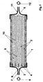
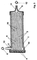
- the bundle contained in the housing includes several side by side arranged hollow fiber membranes.
- bundles also consist of a single hollow fiber membrane.
- the bundle can also consist of several sub-bundles be composed.
- Membrane module opens the at least one inlet device into the outside space and is adjacent to the sealing compound.
- Membrane module stands the at least one inlet device with a distribution room in connection, the front is adjacent to the potting compound and spatially by the potting compound is separated from the outside.
- the distribution room according to a preferred embodiment in the potting compound inserted passages in connection with the outside space, and the lumens of the hollow fiber membranes are embedded on theirs first ends closed. In the simplest case it is in these passages to pass through the potting compound Holes.
- the passages are advantageous formed as fluid permeable elements, which together with the hollow fiber membranes are embedded in the potting compound, wherein particularly good experience with such elements in shape made by capillaries or tubes.
- Membrane module is the fluid to be treated in the outside the hollow fiber membranes initiated.
- the outlet device is located expediently in this case in the range of second end of the hollow fiber membranes, i.e. on the potting compound opposite end of the housing. This flows through Treating fluid as the primary stream the outside space around the hollow fiber membranes essentially along the length of the Hollow fiber membranes towards the outlet device. In these cases is due to the exterior around the hollow fiber membranes formed a channel system for the primary current.
- Part of the primary flow essentially flows through the pressure gradient over the entire extent of the hollow fiber membranes as permeate through their semipermeable, porous wall. This is done the substance-specific treatment on this partial flow. Subsequently the substream treated specifically for the substance enters the lumens of the hollow fiber membranes, which are used here as a collecting space for serve the permeate. The lumens or the collecting space leaves the Permeate flow through the openings at the second end of the hollow fiber membranes and unites with the one flowing through the channel system Primary stream, before that of primary stream and permeate combined stream as treated fluid via the outlet device is discharged from the housing.
- Membrane module stands the at least one inlet device also in connection with a distribution room, the is adjacent to the potting compound and by the potting compound is spatially separated from the outside.
- the fluid to be treated flows as a primary stream over the inlet device of the housing in the distribution room and from this into the lumens of the hollow fiber membranes, flows through them in their longitudinal extension and leaves them through their opening on second, not embedded end of the hollow fiber membranes.
- the Primary current flows through the hollow fiber membranes on the lumen side, in which case the entirety of the lumens of the hollow fiber membranes train the duct system for the primary current.
- the partial flow treated in a substance-specific manner enters the hollow fiber membranes surrounding exterior from that in this embodiment serves as a collecting space for the permeate.
- This outside space flows through the permeate stream in the direction of the outlet device of the housing and unites in the outside space within the housing with that from the duct system, i.e. the primary stream flowing out.
- the treated fluid, i.e. the fluid flow combined from primary flow and permeate becomes derived from the housing via the outlet device.
- the outlet device are in different positions along the housing, however, it is preferably in the vicinity of the sealing compound.
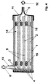
- the inventive Membrane module at least one inlet device, which opens into the outside space and is adjacent to the casting compound, and at least one inlet device connected to a distribution space is connected, the face of the potting compound adjacent is and due to the potting compound spatially from the outside is separated, this distribution space with the lumens of Hollow fiber membranes related to their first End through the potting compound and at this end are open.
- This makes it possible, in particular, in turns a fluid as the primary flow on the lumen side through the hollow fiber membranes and a fluid as a primary flow on the outside to let the outside flow.
- one Fluids for removing certain target substances contained in the fluid e.g. via adsorption to suitable groups in the Membrane first the fluid to be treated as the primary flow Flow through the hollow fiber membranes on the lumen side, as described a partial flow as permeate the walls of the hollow fiber membranes Flows through from the inside out. After completion of the substance-specific treatment can then be used to elute the Membranes adsorbed target substances as an elution fluid Primary flow flows around the outside of the hollow fiber membranes, whereby a partial flow as permeate the walls of the hollow fiber membranes Flows through to the inside and absorbs the target substances.
- the reverse driving style is also possible, i.e. Introducing the fluid to be treated into the exterior and then introducing the elution fluid into the lumens of the Hollow fiber membranes.
- Such an embodiment, in which the first alternate Fluid as primary flow on one side of the hollow fiber membranes and then another fluid as the primary stream on the can flow to the other side of the hollow fiber membrane can be advantageous also in the substance-specific treatment of suspensions use if there are particles in the suspension settle in or on the pore structure of the hollow fiber membranes can.
- the first step in the process is the primary current in the membrane module according to the invention to the introduced one side of the hollow fiber membranes, with the Permeate flow particles of appropriate size in the pore structure washed in or washed onto the pore structure of the membrane can be.
- the primary flow or a second fluid to the other Side of the hollow fiber membranes initiated as a primary stream, and it is formed due to the prevailing pressure conditions Permeate stream, which is compared to the permeate stream in the first process step the walls of the hollow fiber membranes in reverse Direction flows through and the membrane structure of the previous washed-in or washed-up particles. It can second fluid also elution liquid for in the first Process step also retained in the membrane structure be further target substances.
- the aim is that as high a proportion of their per hollow fiber membrane total volume of semi-permeable defined by its outer contour porous membrane wall, in which the substance-specific Treatment can be done.
- the one flowing through the semipermeable walls of the hollow fiber membranes Permeate flow through along the hollow fiber membranes determines the primary flow generated pressure gradient dp / dx.
- dp is the differential pressure change along a differential Distance dx in the direction of the primary current.
- the pressure drop in the direction of the longitudinal extension a hollow fiber membrane, i.e. along that of the primary current flow through channel system takes place with increasing throughput the channel system, i.e. with increasing primary current.
- the amount of the pressure drop dp / dx also increases the smaller are the flow cross sections of the channels from which the channel system flowed through by the primary current, i.e. so the smaller - depending on the embodiment - the cross section the lumens or the spaces between the hollow fiber membranes and between hollow fiber membranes and the inner wall of the housing is.
- the channels of the channel system arise in connection with suitable throughputs through the or flow velocities sufficiently high pressure gradients in the duct system to diffusive transport through the porous membrane structure much larger convective transport due to the permeate flow to overlay.
- the cross sections of the channels should not be too small so that - such as in the substance-specific treatment of suspensions, the one to be treated Fluid can still flow freely through the channels.
- Hollow fiber membranes are preferred in the membrane module according to the invention used, whose walls are essentially one have uniform thickness. In this way it is also achieved that the permeate flow when flowing through the membrane essentially the same at every point of a hollow fiber membrane Flow paths cover what is possible with regard to one uniform residence time of the fluid to be treated is particularly important Advantage is.
- the bundled hollow fiber membranes spaced from each other by spacers be so that there is an outer space around the hollow fiber membranes with defined gaps between the hollow fiber membranes formed. This ensures an even flow of the individual hollow fiber membranes of the bundle.
- the hollow fiber membranes through the primary flow through the spacers the size of the flow cross-sections of the channels of the Adjust hollow fiber membranes surrounding channel system, with what Influence on the pressure gradient occurring in the channels can be taken.
- a spacer is also used in the exterior Adaptation to the size of those contained in the suspension Allows particles.
- the spacers are expediently designed such that they have an elastic component.
- This can be a such bundle of hollow fiber membranes in a simple manner in the Housing of the membrane module can be introduced by first is slightly compressed, the distance between the hollow fiber membranes is slightly reduced in the housing is inserted and then relaxed, which causes the distance between the hollow fiber membranes increases again. As a result, the bundle of hollow fiber membranes is achieved abuts on the outer circumference of the housing inner wall, and an undesirable edge flow along the inside wall of the housing is avoided.
- the hollow fiber membranes within a bundle are preferred kept at a distance by textile threads. In principle, it is enough it, the textile threads between the hollow fiber membranes to lay.
- the hollow fiber membranes are preferred by means of the spacers in at least one hollow fiber mat involved, with these spacers especially is preferably textile threads.
- Such hollow fiber mats can advantageously be used as a knitted mat by known methods, Weaving mat or ribbon, but also as a knitting or as Make a crochet mat.
- weaving or knitting are the textile threads that run across the hollow fiber membranes running weaving or warp threads. Through these cross threads the hollow fiber membranes advantageously against each other evenly spaced and essentially within the mats arranged parallel to each other.
- Mats can be made up of bundles of hollow fiber membranes, which have a high order and in which between the Hollow fiber membranes formed a uniform channel system can be.
- the membrane module according to the invention are the hollow fiber membranes by means of flat, preferably strip-shaped connecting elements in the respective Hollow fiber mat integrated, these strip-shaped connecting elements act as a spacer at the same time.
- Such strip-shaped connecting elements can cross, however also at a different angle to each other advantageously essentially parallel hollow fiber membranes run and are point-like, for example applied adhesive e.g. based on polyurethane on laminated.
- Such mats of hollow fiber membranes are preferably used a stack or a bundle of individual in width layered according to dimensioned mat layers.
- the Hollow fiber membrane mats can, however, also advantageously have one layer or stacked on top of each other in a zig-zag shape Stack or folded into a bundle.
- the individual Windings or the individual layers expediently kept apart from each other, e.g. by means of the woven or knitted threads or inserted connecting elements and optionally by means of additional between the individual Spacers in the form of winding layers of fluid-permeable nonwovens or fabrics.
- Another advantageous embodiment are bundles that consist of at least two superimposed hollow fiber mats, in which the hollow fiber membranes within each mat in a mutual Spaced from each other by spiral Wrapping around an axis or core has been made are, the hollow fiber mats are superimposed so that the hollow threads of the superimposed hollow fiber mats in an intersecting arrangement are brought.
- the production such a bundle is described in detail in EP-A-0 285 812 described.
- the can be between the intersecting angles forming hollow fiber membranes are between 0 ° and 120 °, angles have been found to be favorable exposed between 30 ° and 90 °.
- the in the hollow fiber membrane bundle contained in the membrane modules according to the invention from core bundles arranged around a supporting thread Contain hollow fiber membranes, the one around the support thread arranged hollow fiber membranes with at least one winding thread are wrapped.
- the support threads in the Core bundles contain hollow fiber membranes at a distance from each other held.
- the winding threads ensure one Spacing of the hollow fiber membrane bundle Core bundles with each other, so that overall a good flow around of the hollow fiber membranes contained in the hollow fiber membrane bundle is guaranteed.
- Such composed of core bundles Hollow fiber membrane bundles are described in EP-A-0 732 141.
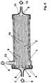
- steps b) and c) of the invention Be repeated several times. This leaves can be achieved in that in the housing in the direction of the longitudinal extent of the hollow fiber membranes several hollow fiber membrane bundles are arranged as steps in a row. Such a series connection of several levels is appropriate Design of the housing and the transitions between the individual Levels both in embodiments of the membrane module possible in which the primary flow through the lumens of the hollow fiber membranes is conducted, as well as in embodiments, at which the primary current the outer space around the hollow fiber membranes flows through.
- the length of the individual step can be i.e. in its dimension in the direction of the longitudinal extension of the in their contained hollow fiber membranes kept short and thereby a change in concentration with regard to possible critical Components in the fluid to be treated can be avoided.
- This is particularly substance-specific in such processes
- Treatment of suspensions of importance in which at least part of the suspended particles through the semipermeable Membrane wall of the hollow fiber membranes is to be retained and at the same time too high concentrations of suspended Particles should be avoided, e.g. in the substance-specific treatment of blood.
- comparative short hollow fiber membranes will run along the hollow fiber membranes only a small partial flow was withdrawn from the primary flow, so that the Concentration changes until the following merge of Primary and permeate flow remain low.
- the number is preferably in the membrane module according to the invention the steps in the housing between 1 and 100.
- Well proven has a number of steps between 1 and 10. It is advantageous if the individual stages are spaced apart to neither the primary stream nor the permeate stream locally by following in the flow direction of the housing order to impede the level and to ensure thorough mixing of primary flow and permeate flow.
- a uniform mixing is an advantage, e.g. undesirable Avoid fluctuations in concentration.
- the fluid to be treated recirculates and goes through the treatment process several times until a desired one Degree of treatment is reached.
- Hollow fiber membranes with different outer contours ie with different outer contours when viewed in cross section, can be used.
- the hollow fiber membranes can, for example, have an essentially round or circular, triangular, quadrangular, hexagonal or octagonal contour, they can also be oval, elliptical, three-lobed, four-lobed, etc.
- hollow fiber membranes with a wall thickness between 15 ⁇ m and 1500 ⁇ m have proven successful; hollow fiber membranes with a wall thickness between 100 ⁇ m and 300 ⁇ m have proven to be very effective.
- a and U denote the sum of the areas or circumferences of the individual lumens of the respective hollow fiber membrane. Hollow fiber membranes with a hydraulic diameter between 200 ⁇ m and 400 ⁇ m are particularly preferred.
- the ranges given above with regard to the hydraulic diameter apply analogously to the cross sections of the channels of the channel system formed by the outer space around the hollow fiber membranes.
- the hydraulic diameter d h of the hollow fiber membranes is preferably 1.2 to 12 times smaller than the hydraulic diameter d h1 of the channels.
- the permeate stream flows through the semipermeable wall of the hollow fiber membranes and convectively transports the target substance through the membrane.
- the semipermeable, porous wall of the hollow fiber membranes has a pore size that is convective Permits transport of the target substance through the membrane wall.
- the permeate flow is of course maximized if the average pore size of the membranes is maximized.
- the pore size must also match the size of the Target substance that is in the form of dissolved macromolecules, but also in the form of small particles with a particle size can be in the sub-micrometer range.
- the membrane separating function and contained in the suspension Holds back components that are not target substances.
- the pore size has a certain maximum value must not exceed. This can block the pore system or for example undesirable interactions between such restrained components with Interaction with the target substances provided Prevents substance-specific groups in the membrane become.
- the membrane module according to the invention may be with regard to the following applications of the membrane module according to the invention or embodiments of the method according to the invention rather be important to use membranes with the smallest possible pore sizes and the largest possible pore volume or the greatest possible porosity to be used in order to achieve a the largest possible inner, i.e. surface formed by the pores to provide the membrane.
- the hollow fiber membranes used according to the invention are medium Porosity between 50 vol.% And 90 vol.%.
- As a middle one Porosity becomes the ratio of the pore volume of the hollow fiber membrane understood the wall volume of the hollow fiber membrane, where the wall volume is made up of the pore volume and the volume of the material making up the membrane structure.
- the requirements for the construction of the hollow fiber membrane i.e. on their structure and pore size distribution over the wall thickness result from the respective application of the substance-specific Treatment.
- the membrane structure can over the wall thickness be isotropic, i.e. inside the membrane wall are the pore diameters essentially constant, they can be anisotropic, be symmetrical or asymmetrical, and the membrane can on one side a layer with a much denser pore structure, i.e. have skin.
- the denser layer can be the primary current or membrane but facing the collection room for the permeate.
- Suspensions may be required to achieve the membrane a small pore diameter for a certain separation effect the side facing the primary current.
- the membrane wall obtained, but the rest of the membrane structure is expedient coarser, but depending on the application not too coarse, in order to achieve the largest possible inner surface.
- Hollow fiber membranes with an average pore diameter are preferred between 0.005 and 5 ⁇ m, particularly preferably those with an average pore diameter between 0.1 and 3 ⁇ m used.
- anisotropic membranes e.g. a layer with denser Pore structure are used to determine the mean Pore diameter within the denser layer also the cited determination methods based on filtration experiments used.
- the Hollow fiber membranes in their wall covering at least 80% of the Wall thickness an essentially constant mean pore diameter exhibit. This allows a high inner Surface combined with a large number of immobilized, substance-specific groups in the membrane at the same time low pressure loss when flowing through the membrane wall and thus achieve a high permeate flow. As an im becomes a substantially constant mean pore diameter understood those who are no longer concerned about the wall thickness changes as +/- 50%.
- Porous hollow fiber membranes with a large inner surface are preferably used in the membrane module according to the invention or for carrying out the method according to the invention.
- Hollow fiber membranes with a BET surface area between 2 and 300 m 2 per cm 3 wall volume have proven themselves, hollow fiber membranes with a BET surface area between 8 and 30 m 2 per cm 3 wall volume have proven themselves.
- the BET method for determining the surface of porous membrane structures which is based on nitrogen adsorption measurement, is described by K. Kaneko, J. Membrane Science 96 (1994), 59-89.
- Membranes made of inorganic materials such as glass, ceramic, SiO 2 , carbon or metal, organic polymers or mixtures thereof can be used.
- the polymers can have a hydrophilic and / or hydrophobic character, they can be selected from the group of cellulosic polymers, such as cellulose or regenerated cellulose, modified cellulose, such as cellulose esters, cellulose ethers, amine-modified celluloses, and mixtures of cellulosic polymers from the group synthetic polymers such as polyacrylonitrile and corresponding copolymers, polyurethane-containing polymers, polyarylsulfones and polyaryl ether sulfones, such as polysulfone or polyethersulfone, polyvinylidene fluoride, polytetrafluoroethylene, water-insoluble polyvinyl alcohols, aliphatic and aromatic polyamides, polyimides, polyetherimides
- polymers such as polyethylene oxide, polyhydroxy ether, polyethylene glycol, polyvinyl pyrrolidone, polyvinyl alcohol or polycaprolactone, or inorganic substances such as SiO 2, for example, can be added to these polymers or polymer mixtures.
- the membrane can also have been subjected to a surface modification, for example, in order to adjust certain properties of the membrane surface, for example in the form of certain functional groups. If polyolefinic polymers are used, it may be necessary to coat at least the inner surface of the membrane, for example with a functionalizable polymer.
- cellulosic membranes Polymers, polyamides, polypropylene, polyether sulfones or made from solvent-stable and pH-stable polymers, especially with membranes made of polytetrafluoroethylene or polyvinylidene fluoride, and modifications derived therefrom, Blends, blends or copolymers.
- membranes are described for example in DE-A-39 23 128.
- the inner cross section is expediently to the particular use of the invention Membrane module or to the contour of those contained in the housing Adjusted bundle.
- housings with a square, rectangular, hexagonal, octagonal or also round inner cross section used.
- the hollow fiber membrane bundles which are preferred Have spacers with an elastic component, under a little compression and relaxation positioned in the housing. Then the hollow fiber membranes according to methods known per se on their first End embedded in a sealing compound in a fluid-tight manner in the housing.
- the housings are in one preferred embodiment has an inner cross section on the along the hollow fiber membranes towards the second Tapered end, i.e. the cross-sectional area of the housing decreases in this direction. This will make the distance between the hollow fiber membranes towards their second, not embedded end reduced and the pressure drop and thus the Permeate flow increased. At the same time, it can be used to equalize of the permeate stream over the longitudinal extent of the Achieve hollow fiber membranes.
- the membrane module according to the invention or the inventive The process can lead to a wide variety of substance-specific treatments of fluids are used.
- fluids to be treated suspensions are preferred.
- Particularly good ones Treatment results are achieved when the method according to the invention the membrane module according to the invention is used, being on and / or in the hollow fiber membranes preferably substance-specific groups are immobilized.
- too different substance-specific groups on and / or be immobilized in the hollow fiber membranes that are specific with various contained in the fluid to be treated Interact with target substances.
- too different hollow fiber membranes with different ones substance-specific groups can be used together.
- membrane modules with several stages in the hollow fiber membranes of the individual stages are the same, however also different substance-specific groups be immobilized.
- these substance-specific groups can be adsorptive or coupled to the membrane via covalent bonds.
- This coupling to the membrane can be done both before installation in the housing as well as after inserting the membrane into the housing of the membrane module according to the invention take place. You can do this in coordination depending on the respective application acting groups, for example, essentially homogeneous to the entire surface of the porous membrane, i.e. both to the outer, facing the lumens and the outer space Surfaces, as well as on the inner, formed by the pores Surfaces coupled, i.e. immobilized on and in the membrane his. But it may also be necessary that the groups acting on specific substances only on a part of them Surfaces are immobilized, for example when individual components of the fluid to be treated is not specific to the substance active groups should come into contact.
- substance-specific groups in the membrane matrix are possible in the case of membranes polymeric materials, for example by modifying the polymer material with, for example, ionic, hydrophilic or hydrophobic groups or by using polymer blends which at least one polymer component is substance-specific has active groups.
- Another option is there in such substance-specific groups or carrier substances or particles having such groups in the pore system of a membrane in the manufacturing process of Store the membrane or add it to the finished membrane e.g. cooperateschwemmen.
- the membrane has expediently an asymmetrical structure and optionally a skin, the openings of the skin or the Pores of the more porous side of the membrane are dimensioned so that the substance-specific groups or the named carrier substances or particles cannot pass through.
- the pore size of the membrane used is too large choose that even despite being immobilized in the pores substance-specific groups, the target substances convectively of at least a portion of the fluid to be treated through the Membrane wall can be transported.
- Ligands for the affine separation of ligates from those to be treated Liquids or around catalysts, taking catalysts also biocatalysts such as Enzymes are to be understood.
- preferred Processes according to the invention are purification / separation processes ligates from a ligate-containing liquid, wherein hollow fiber membranes are selected on and / or in which Ligands for said ligates are immobilized, or membrane modules according to the invention are used, the such Contain hollow fiber membranes.
- ligands can, depending on the application act non-specifically, group-specifically or specifically.
- Possibilities for their immobilization are explained in the explanations in European patent application EP 787 523 referred to, the disclosure of which was expressly referred to here becomes.
- the membrane module according to the invention or the inventive Process is for numerous cleaning / separation applications of ligates from a ligate-containing liquid, such as they, for example, generally from the area of affinity chromatography are known, taking affinity chromatography biospecific adsorption or also ion exchange chromatography or metal chelate chromatography be understood.
- liquids can be hollow fiber membranes be selected on and / or in which according to itself known methods immobilized enzymes or catalysts are.
- membrane module according to the invention or the method according to the invention catalytic treatments is again based on the explanations in European patent application EP 787 523 referred to, the disclosure of which was expressly referred to here becomes.
- the spacers located between the hollow fiber membranes can do other than the spacer function itself Perform functions. So - except on and / or in the porous membrane wall of the hollow fiber membranes also substance-specific active groups immobilized on the spacers his.
- the spacers are advantageous for this purpose from the same polymer or the same polymer family as the membrane material.
- Especially for between the mats spacers inserted from hollow fiber membranes have proven textile fabrics, such as those e.g. by Y. Yang et al., J. Chromatographie 598 (1992), 169-180. there guide fabrics with multifilament threads with a single thread diameter between 1 ⁇ m and 30 ⁇ m for particularly good results. Fabrics that both the weft and also the warp threads at an angle to the direction of the primary current have a value between 30 ° and 60 ° having.
- Figure 1 shows a membrane module according to the invention with a Housing 1, which contains hollow fiber membranes 2 arranged as a bundle.
- the hollow fiber membranes 2 are 3 in at one end a potting compound 4 embedded and at its second end 5 in a fluid can flow around it essentially free.
- the fluid to be treated is passed through the inlet device 7 into the distribution space 8, towards which the hollow fiber membranes 2 with their embedded End 3 are open.
- Fluid as primary flow in the lumens 9 of the hollow fiber membranes 2 initiated and flows through the hollow fiber membranes towards their non-embedded end 5. Because of the pressure drop arising during the flow through the lumens flows along the hollow fiber membranes 2 a part of the primary current as a permeate flow through the porous semipermeable wall of the Hollow fiber membranes 2 in the surrounding the hollow fiber membranes Outside space 10, the partial flow flowing through the wall being a undergoes substance-specific treatment.
- the substance-specific treated permeate is collected in the exterior 10 and flows through it in the direction of the outlet device 11, which is in the area of the non-embedded ends 5 of the Hollow fiber membranes 2 with the flowing out of the lumens 9 Primary stream combined.
- the one made up of primary stream and permeate Fluid flow leaves the membrane module as treated fluid 12 via the outlet device 11 which in the case of FIG membrane module shown at the non-embedded ends 5 of the hollow fiber membranes 2 facing the end of the housing 1 is arranged.
- the arrangement of the outlet device on the non-embedded Ends 5 of the hollow fiber membranes 2 facing the end of the housing 1 represents only one of several possibilities. As shown in FIG. 2, preference is given to the case of lumen-side supply of the primary current according to FIG. 1, the outlet device 11 adjacent to the potting compound 4 and thus towards the first, embedded ends 3 of the hollow fiber membranes 2 arranged. In this case also flows through Primary flow after exiting the lumens 9 of the hollow fiber membranes 2 at their non-embedded ends 5 the directly the hollow fiber membranes 2 surrounding outer space 10 and leaves, mixed with that also flowing through the outer space 10 Permeate flow as treated fluid 12, the housing 1 over the Outlet device 11.
- a membrane module is shown in which the one Bundle of hollow fiber membranes 2 outside of Flow around primary current.
- the housing 1 at the level of the inlet device 13 an extension 14 of the diameter to a more uniform Distribution of the fluid to be treated as a primary flow to reach across the entire bundle cross-section.
- the first Ends 3 of the hollow fiber membranes 2 are in this embodiment embedded in the sealing compound 4 so that the lumens 9 by means of the sealing compound 4 are closed at this end.
- the fluid 6 to be treated flows through the inlet device 13 into and into the outer space 10 surrounding the hollow fiber membranes 2 flows through this outer space 10 as a primary flow essentially along the hollow fiber membranes 2 towards the outlet device 11. Due to the pressure drop that occurs Permeate flow essentially over the entire extent of the Hollow fiber membrane bundle through the semi-permeable, porous walls the hollow fiber membranes 2 in their lumens 9. On which the Walls of the hollow fiber membranes 2 flowing permeate stream takes place the substance-specific treatment.
- the treated permeate stream leaves the lumens 9 through the openings on the second End 5 of the hollow fiber membranes 2 and unites there in the outer space 10 with the primary current before the primary current and Permeate combined stream as treated fluid 12 via the outlet device 11 is discharged from the housing 1.
- a membrane module of the type shown in Figure 3 in which the hollow fiber membranes arranged in a bundle on the outside are surrounded by the primary current, it is important for one even distribution of the fluid to be treated over the bundle cross-section to care. In principle, this can be achieved be that when flowing through the outside space or the duct system formed by the exterior Flow resistance is sufficiently high, such as through Introducing elements into this outdoor space for an increase the flow resistance.
- Figure 4 are - in Flow direction between inlet device 13 and outlet device 11 seen - tubular or capillary-shaped elements 15 introduced into the outer space 10 around the hollow fiber membranes 2, for an increase in flow resistance in the inlet device 13 adjacent part of the outdoor space 10 and so an equalization of the distribution of the primary current cause.
- the membrane module shown in FIG. 4 also includes in the area of the non-embedded ends 5 of the hollow fiber membranes 2 additional flow resistance increasing elements 16 introduced into the outer space 10.
- additional flow resistance increasing elements 16 introduced into the outer space 10.
- tubular or capillary Elements 16 can be the flow resistance for the Primary current when flowing through the outside space results, increase and in this way the permeate flow through the walls enlarge the hollow fiber membranes.
- tubular or capillary elements instead of tubular or capillary elements
- other flow resistance increasing Elements are used, for example in Form of appropriately designed fluid-permeable spacers or in the form of fluid-permeable nonwovens, for example for hollow fiber membrane bundles that consist of a spiral around one Core-wound hollow fiber membrane mats are formed, placed in strips between the layers created during winding become.
- FIG. 5 shows a membrane module according to the invention, which both has an inlet device 7 with a distribution space 8 and over this with the lumens 9 of the hollow fiber membranes 2 in Connected, as well as an inlet device 13, which in the outer space 10 surrounding the hollow fiber membranes 2 opens and is adjacent to the sealing compound 4.
- the membrane module according to the invention can different fluids alternating as primary flow on the lumen side through the hollow fiber membranes and outside through the Outside space.
- a specific one to be treated can first be treated Fluid containing target substances via the inlet device 7 introduced as a primary flow into the lumens 9 of the hollow fiber membranes 2 are closed, the inlet device 13 remains.
- a permeate stream is formed in the manner already described through the semi-permeable, porous walls of the hollow fiber membranes 2, and there is a substance-specific treatment of the permeate stream, for example, by adsorption of the target substances in the hollow fiber membranes 2 and thus a loading of the hollow fiber membranes 2 with the target substances.
- the one around the target substances impoverished permeate stream is combined with that from the lumens 9 of the hollow fiber membranes 2 emerging primary stream over the Outlet device 11 derived from the housing 1.
- the target substances in a simple way out of the hollow fiber membranes be eluted by adding an elution liquid via the inlet device 13 is introduced into the exterior 10 and the Elution liquid flows through the outer space as the primary stream.
- the inlet device 7 remains closed. Then occurs in the manner already described a permeate flow through the semipermeable porous walls of the Hollow fiber membranes 2, but in the opposite direction as when loading the hollow fiber membranes with the target substances, and elution of the target substances from the Hollow fiber membranes 2 take place.
- FIG. 6 shows a membrane module according to the invention, of the two hollow fiber membrane bundles arranged one behind the other as steps 17, 18 contains the hollow fiber membranes 19, 20 each embedded at one end in casting compounds 21, 22 are.
- the fluid 6 to be treated is via the inlet device 7 introduced into the housing 1 of the membrane module and first flows through the hollow fiber membranes as the primary flow on the lumen side 19 of the first membrane bundle 17.
- the resultant Permeate flow is in the walls of the hollow fiber membranes 19th undergo a first substance-specific treatment.
- the outside space in the area of the first membrane bundle 17th permeate flow flowing through combines in the area of non-embedded ends of the hollow fiber membranes 19 of the membrane bundle 17 with that from the lumens of the hollow fiber membranes 19 emerging primary current, and the resulting current of the simple treated fluid then comes again on the lumen side as primary current in the hollow fiber membranes 20 of the second membrane bundle 18 a.
- the processes are repeated in the area of the first Membrane bundle 17 took place, and in the walls of the hollow fiber membranes 20 of the second bundle 18 takes place on it permeate stream flowing through another substance-specific treatment.
- the fluid stream 12 thus treated twice is about the outlet device 11 is discharged from the membrane module. How executed, can in the hollow fiber membranes of each Levels of immobilized, substance-specific groups too be different so that a fluid to be treated when Flow through a membrane module containing several stages experienced several different substance-specific treatments can.
- FIG. 7 A possibility of connecting several bundles in series of hollow fiber membranes as steps with outside flow the hollow fiber membranes through the primary flow is shown in FIG. 7 shown.
- the fluid to be treated is - as with examples for flow through the primary current on the lumen side - front, i.e. from the embedded ends of the hollow fiber membranes forth, via the inlet device 7 in the before the first stage arranged distribution room 8 directed.
- the distribution room 8 borders on one side of the potting compound 23, by means of of which the hollow fiber membranes 19 of the bundle 17 of the first stage embedded at its end facing the inlet device are that their lumens are closed at these ends.
- these potting compound 23 are also fluid-permeable elements 24 embedded, which in the case shown as tubes or capillaries are trained.
- the fluid to be treated is the primary flow in the Outside space 25 around the hollow fiber membranes 19 of the first membrane bundle 17 headed. As described flows due to the prevailing Pressure conditions a permeate flow through the semipermeable, porous walls of the hollow fiber membranes 19 and there undergo a first substance-specific treatment. In the area the non-embedded ends of the hollow fiber membranes 19 the primary flow combines with the permeate flow in the outside 25th
- the resultant first substance-specific treatment fluid stream undergoes bundle 18 in the second stage the hollow fiber membranes 20 supplied.
- This level is analogous to first stage executed.
- the sealing compound 26 fluid-permeable elements 24, by means of which the other fluid to be subjected to in the substance-specific treatment Outside space 27 around the hollow fiber membranes 20 of the second bundle 18 is directed.
- the processes taking place here correspond those in the first stage, the permeate stream being the second stage subjected to a further substance-specific treatment becomes.
- the fluid stream 12 then treated twice becomes then passed through the outlet device 11 from the membrane module.
- FIG. 8 A modification of the membrane module shown in Figure 7 with two hollow fiber membrane bundles arranged one behind the other as steps 17.18 and outside flow around the hollow fiber membranes 19, 20 through the primary current is shown in FIG. 8. at the membrane module according to FIG. 8 is initiated treating fluid 6 also via the inlet device 7. The primary current is then from the front, i.e. of the Level forth, each by the potting compound 23.26 and the embedded, ends of the sealing compound 23, 26 closed Hollow fiber membranes 19, 20 is formed in the respective outer space 25.27 passed around the hollow fiber membranes.
- the housing 1 Around the embedded ends of the hollow fiber membranes 19, 20 of the respective Bundles 17, 18 around are fluid-permeable in the form of a ring Elements 28.29 embedded in the casting compounds 23.26, which in the shown example formed as short tubes or capillaries are and which pass through the casting compounds 23, 26.
- the housing 1 In the area of the casting compounds 23, 26, the housing 1 has extensions 30.31 with respect to its inner diameter. hereby on the one hand, a uniform supply of the to be treated Fluids to the fluid-permeable elements 28.29 reached. To the others are 30.31 ring channels 32.33 through these extensions formed behind the casting compounds 23, 26 in the direction of flow, into which the fluid-permeable elements 28, 29 open and through which an even distribution of the primary current over the respective Bundle cross section is reached.
Abstract
Claims (28)
- Module de membranes pour le traitement spécifique d'un fluide, comprenantcaractérisé par le fait que les lumières (9) des membranes à fibres creuses (2; 19, 20), à la seconde extrémité (5) de ces dernières, sont ouvertes et débouchent dans l'espace extérieur (10; 25, 27), un grand nombre de groupes fonctionnels qui entrent en interaction avec les fluides à traiter s'écoulant à travers la membrane, étant couplés aux membranes.a) une enveloppe (1) ayant une direction longitudinale,b) à l'intérieur de cette enveloppe (1), essentiellement dans la direction longitudinale de cette dernière, un faisceau de membranes à fibres creuses (2; 19, 20) ayant une paroi semi-perméable de structure poreuse, chaque membrane à fibres creuses (2; 19, 20) présentant une première et une seconde extrémités (3, 5) et au moins une lumière (9) s'étendant le long de l'axe longitudinal de la membrane, chaque membrane à fibres creuses étant scellée dans l'enveloppe (1) uniquement à sa première extrémité (3) à l'aide d'une masse de scellement (4; 21, 22; 23, 26) et permettant un écoulement essentiellement libre du fluide autour d'elle à sa seconde extrémité (5), les membranes à fibres creuses (2; 19, 20) étant entourées d'un espace extérieur (10; 25, 27) délimité par la paroi intérieure de l'enveloppe (1) et par la masse de scellement (4; 21, 22; 23, 26) et présentant chacune un côté intérieur tourné vers ladite au moins une lumière (9) et un côté extérieur tourné vers ledit espace extérieur (10; 25, 27),c) au moins un dispositif d'entrée (7, 13) pour l'admission du fluide (6) à traiter dans l'enveloppe (1) sur un seulement des deux côtés des membranes à fibres creuses (2; 19, 20),d) un dispositif de sortie (11) pour l'évacuation du fluide (12) traité de l'enveloppe (1), le dispositif de sortie (11) étant ouvert vers l'espace extérieur (10) autour des membranes à fibres creuses (2; 19, 20),
- Module de membranes suivant la revendication 1, caractérisé par le fait que ledit dispositif d'entrée (13) au nombre d'au moins un débouche dans l'espace extérieur (10) et est voisin de la masse de scellement (4).
- Module de membranes suivant la revendication 2, caractérisé par le fait que les lumières (9) des membranes à fibres creuses (2) sont fermées à la première extrémité (3) scellée de ces dernières.
- Module de membranes suivant la revendication 1, caractérisé par le fait que ledit dispositif d'entrée (7) au nombre d'au moins un se trouve en communication avec un espace distributeur (8) qui côté frontal est voisin de la masse de scellement (4; 21, 22; 23, 26) et est séparé de l'espace extérieur (10; 25, 27) par la masse de scellement (4; 21, 22; 23, 26).
- Module de membranes suivant la revendication 4, caractérisé par le fait que l'espace distributeur (8) se trouve en communication avec les lumières (9) des membranes à fibres creuses (2; 19, 20) dont la première extrémité (3) traverse la masse de scellement (4; 21, 22) et qui sont ouvertes à cette extrémité.
- Module de membranes suivant la revendication 4, caractérisé par le fait que l'espace distributeur (8) se trouve en communication avec l'espace extérieur (10; 25, 27) autour des membranes à fibres creuses (2; 19, 20) à travers des passages (24; 28, 29) pratiqués dans la masse de scellement et que les lumières (9) des membranes à fibres creuses (2; 19, 20) sont fermées à la première extrémité (3) scellée de ces dernières.
- Module de membranes suivant la revendication 6, caractérisé par le fait que les passages (24; 28, 29) sont des éléments perméables au fluide.
- Module de membranes suivant la revendication 7, caractérisé par le fait que les éléments perméables au fluide sont des capillaires ou tubes.
- Module de membranes suivant la revendication 1, caractérisé par le fait qu'au moins un dispositif d'entrée (13) débouche dans l'espace extérieur (10) et est voisin de la masse de scellement (4) et au moins dispositif d'entrée (7) se trouve en communication avec un espace distributeur (8) qui côté frontal est voisin de la masse de scellement (4) et est séparé de l'espace extérieur (10) par la masse de scellement (4), et que cet espace distributeur (8) se trouve en communication avec les lumières (9) des membranes à fibres creuses (2) dont la première extrémité (3) traverse la masse de scellement (4) et qui sont ouvertes à cette extrémité.
- Module de membranes suivant une ou plusieurs des revendications 1 à 9, caractérisé par le fait que les membranes à fibres creuses (2; 19, 20) d'un faisceau sont maintenues à distance réciproque par des espaceurs.
- Module de membranes suivant la revendication 10, caractérisé par le fait que les membranes à fibres creuses (2; 19, 20) sont liées à l'aide des espaceurs dans au moins une nappe de fibres creuses.
- Module de membranes suivant une ou plusieurs des revendications 1 à 11, caractérisé par le fait que plusieurs faisceaux (17, 18) de membranes à fibres creuses (19, 20) sont disposés dans l'enveloppe (1) en étages les uns derrière les autres dans la direction longitudinale des membranes à fibres creuses (19, 20).
- Module de membranes suivant une ou plusieurs des revendications 1 à 12, caractérisé par le fait que les membranes à fibres creuses (2; 19, 20) présentent une surface BET comprise entre 2 et 300 m2 par cm3 de volume de membranes.
- Module de membranes suivant la revendication 13,
caractérisé par le fait que la surface BET est comprise entre 8 et 30 m2 par cm3 de volume de membranes. - Module de membranes suivant une ou plusieurs des revendications 1 à 14, caractérisé par le fait que les membranes à fibres creuses (2; 19, 20) sont constituées de cellulose, polyamide, polypropylène, polysulfone, polytétrafluoréthylène ou poly(fluorure de vinylydène) ou de variantes modifiées, d'alliages, de mélanges ou de copolymères de tels polymères.
- Module de membranes suivant une ou plusieurs des revendications 1 à 15, caractérisé par le fait que des groupes à action spécifique sont immobilisés sur et/ou dans les membranes à fibres creuses (2; 19, 20).
- Module de membranes suivant la revendication 16, caractérisé par le fait que les groupes à action spécifique sont des ligands pour la séparation par affinité de partenaires de liaison dans un fluide à traiter.
- Module de membranes suivant la revendication 16, caractérisé par le fait que les groupes à action spécifique sont des catalyseurs.
- Procédé pour le traitement spécifique d'un fluide avec utilisation d'un module de membranes suivant la revendication 1, les membranes à fibres creuses (2; 19, 20) présentant chacune un côté intérieur tourné vers la au moins une lumière (9) et un côté extérieur tourné vers l'espace extérieur (10; 25, 27), comprenant au moins les étapes suivant lesquelles:a) on introduit dans l'enveloppe (1) le fluide (6) à traiter,b) on fait s'écouler le fluide (6) à traiter en tant que flux primaire sur un premier des côtés des membranes à fibres creuses (2; 19, 20) de manière qu'une partie de ce flux primaire entre en tant que flux de perméat depuis ce premier côté dans la paroi des membranes à fibres creuses (2; 19, 20), traverse la paroi vers le second des côtés, le traitement spécifique du fluide ayant lieu sur la partie du fluide à traiter constituant le flux de perméat, et quitte ensuite la paroi sur le second côté,c) on réunit le flux de perméat ayant traversé la paroi des membranes à fibres creuses (2; 19, 20), après le traitement spécifique, avec le flux primaire s'écoulant sur ledit premier côté des membranes à fibres creuses (2; 19, 20),d) on fait sortir de l'enveloppe (1) le flux de fluide (12) traité réuni à partir du flux primaire et du flux de perméat.
- Procédé suivant la revendication 19, caractérisé par le fait qu'on effectue plusieurs fois les étapes b) et c).
- Procédé suivant la revendication 20, caractérisé par le fait qu'on effectue le traitement du fluide dans plusieurs faisceaux (17, 18) de membranes à fibres creuses (2; 19, 20) disposés en étages successifs dans la direction longitudinale des membranes à fibres creuses (2; 19, 20).
- Procédé suivant la revendication 21, caractérisé par le fait que le nombre des étages est compris entre 1 et 100.
- Procédé suivant une ou plusieurs des revendications 19 à 22, caractérisé par le fait qu'on fait recirculer le fluide (6) à traiter.
- Procédé suivant une ou plusieurs des revendications 19 à 23, caractérisé par le fait que le fluide (6) à traiter est une suspension.
- Procédé pour la purification/séparation par affinité de partenaires de liaison dans un liquide contenant des partenaires de liaison,
caractérisé par le fait qu'on sélectionne des membranes à fibres creuses (2; 19, 20) sur et/dans lesquelles des ligands pour lesdits partenaires de liaison sont immobilisés, et qu'on met en oeuvre le procédé suivant une ou plusieurs des revendications 19 à 24. - Procédé pour le traitement catalytique de fluides, caractérisé par le fait qu'on utilise des membranes à fibres creuses (2; 19, 20) sur et/dans lesquelles des catalyseurs sont immobilisés, et qu'on met en oeuvre le procédé suivant une ou plusieurs des revendications 19 à 24.
- Utilisation du module de membranes suivant la revendication 17 pour la séparation/purification de partenaires de liaison dans un liquide contenant lesdits partenaires de liaison.
- Utilisation du module de membranes suivant la revendication 18 pour la mise en oeuvre de réactions catalytiques sur des substances-cibles contenues dans des fluides.
Applications Claiming Priority (3)
| Application Number | Priority Date | Filing Date | Title |
|---|---|---|---|
| DE19725199 | 1997-06-14 | ||
| DE19725199 | 1997-06-14 | ||
| PCT/EP1998/003262 WO1998057733A1 (fr) | 1997-06-14 | 1998-06-02 | Module membranaire a membranes en fibres creuses enrobees d'un cote |
Publications (2)
| Publication Number | Publication Date |
|---|---|
| EP0989904A1 EP0989904A1 (fr) | 2000-04-05 |
| EP0989904B1 true EP0989904B1 (fr) | 2002-09-11 |
Family
ID=7832485
Family Applications (1)
| Application Number | Title | Priority Date | Filing Date |
|---|---|---|---|
| EP98928340A Expired - Lifetime EP0989904B1 (fr) | 1997-06-14 | 1998-06-02 | Module membranaire a membranes en fibres creuses enrobees d'un cote |
Country Status (5)
| Country | Link |
|---|---|
| US (1) | US6270674B1 (fr) |
| EP (1) | EP0989904B1 (fr) |
| JP (1) | JP3936748B2 (fr) |
| DE (1) | DE59805523D1 (fr) |
| WO (1) | WO1998057733A1 (fr) |
Cited By (5)
| Publication number | Priority date | Publication date | Assignee | Title |
|---|---|---|---|---|
| DE102009037015A1 (de) * | 2009-08-07 | 2011-02-17 | Michael Hajek | Vorrichtung und Verfahren zur Eliminierung von bioschädlichen Stoffen aus Körperflüssigkeiten |
| DE102010049789A1 (de) * | 2010-10-29 | 2012-05-03 | Fresenius Medical Care Deutschland Gmbh | Vorrichtung zur chromatographischen Auftrennung eines Stoffgemisches und deren Verwendung |
| DE102013010724A1 (de) * | 2013-06-27 | 2014-12-31 | Mann+Hummel Gmbh | Polymeres Vollbluthohlfasermembranfiltermedium und Verwendung davon zum Abtrennen von Blutplasma/-serum von Vollblut |
| DE102013010735A1 (de) * | 2013-06-27 | 2015-01-15 | Mann + Hummel Gmbh | Keramisches Vollbluthohlfasermembranfiltermedium und Verwendung davon zum Abtrennen von Blutplasma/-serum von Vollblut |
| DE102013012676A1 (de) * | 2013-07-31 | 2015-02-05 | Mann + Hummel Gmbh | Vorrichtung zur Querstromfiltration |
Families Citing this family (40)
| Publication number | Priority date | Publication date | Assignee | Title |
|---|---|---|---|---|
| US6849185B1 (en) * | 1999-05-14 | 2005-02-01 | Pall Corp | Charged membrane |
| WO2001066237A1 (fr) * | 2000-03-07 | 2001-09-13 | Mat Adsorption Technologies Gmbh & Co. Kg | Module a elements de membrane pour ecoulement partiel et ecoulement total |
| JP4520621B2 (ja) * | 2000-11-01 | 2010-08-11 | 信和化工株式会社 | クロマトグラフィー用分離カラム、固相抽出用媒体、及びクロマトグラフィーの試料注入システム |
| JP4266637B2 (ja) * | 2001-02-05 | 2009-05-20 | ミリポア・コーポレイション | 微生物の検出 |
| WO2003022393A1 (fr) * | 2001-09-10 | 2003-03-20 | Clemson University | Fibres plastiques evidees en tant que phases fixe/de support pour la separation chimique par chromatographie en phase liquide et pour le nettoyage de flux de dechets |
| US20070071649A1 (en) * | 2001-09-10 | 2007-03-29 | Marcus R Kenneth | Capillary-channeled polymer fibers as stationary phase media for spectroscopic analysis |
| GB2387130A (en) * | 2002-04-04 | 2003-10-08 | Fluid Technologies Plc | Hollow fibre filter membrane unit with microorganism detector, and associated usage |
| DE10236664B4 (de) * | 2002-08-09 | 2016-05-12 | Sartorius Stedim Biotech Gmbh | Verfahren und Vorrichtung zur adsorptiven Stofftrennung |
| US20070017870A1 (en) * | 2003-09-30 | 2007-01-25 | Belov Yuri P | Multicapillary device for sample preparation |
| WO2005032688A1 (fr) * | 2003-09-30 | 2005-04-14 | Chromba, Inc. | Colonne multicapillaire pour la chromatographie et la preparation d'echantillon |
| FI117179B (fi) * | 2004-01-23 | 2006-07-14 | Environics Oy | Kaasukromatografi |
| US7261813B2 (en) * | 2004-08-10 | 2007-08-28 | Clemson University | Monolithic structures comprising polymeric fibers for chemical separation by liquid chromatography |
| US7740763B2 (en) * | 2004-08-10 | 2010-06-22 | Clemson University | Capillary-channeled polymeric fiber as solid phase extraction media |
| DE202004015240U1 (de) * | 2004-09-27 | 2004-12-09 | Silvertex Gmbh | Fadensystem zur Installation in Trinkwassersystemen |
| US20060254984A1 (en) * | 2005-05-16 | 2006-11-16 | Uspolyresearch | Hollow Fiber Membrane Adsorber and Process for the Use Thereof |
| DE102005028718A1 (de) * | 2005-06-20 | 2006-12-28 | Carl Freudenberg Kg | Hohlfaseranordnung |
| KR101016732B1 (ko) * | 2006-04-19 | 2011-02-25 | 아사히 가세이 케미칼즈 가부시키가이샤 | 고내구성 pvdf 다공질 막 및 그 제조 방법 및 이를 이용한 세정 방법 및 여과 방법 |
| DE102006023223B3 (de) * | 2006-05-18 | 2007-11-15 | Bruker Biospin Gmbh | Apparatur zur Analyse einer flüssigen Probe mit einer Multi-Lumen-Kapillare |
| WO2009121034A2 (fr) * | 2008-03-28 | 2009-10-01 | Pelican Group Holdings, Inc. | Dispositifs de préparation d’échantillons multicapillaires et procédés de traitement d’analytes |
| TWI374037B (en) * | 2008-08-21 | 2012-10-11 | Univ Taipei Medical | Bio-acceptable conduits and method providing the same |
| US7875176B2 (en) * | 2009-03-06 | 2011-01-25 | Porous Media Corporation | Membrane module for fluid filtration |
| KR20120091161A (ko) * | 2009-09-30 | 2012-08-17 | 멤브라나 게엠베하 | 유체 불투과성 세그먼트를 갖는 중공 섬유 멤브레인 매트 및 관련 방법 |
| BR112014005221A2 (pt) | 2011-09-08 | 2017-03-28 | Safe Bt Inc | uso de materiais de fibra oca modificada para a remoção de exotoxinas produzidas por escherichia coli a partir de liquidos, de preferência a partir de sangue e de plasma, bem como seu uso para o tratamento de doenças concomitantes |
| EP2762180A4 (fr) * | 2011-09-30 | 2015-05-13 | Toray Industries | Colonne de purification et procédé de fabrication d'une colonne de purification |
| WO2013113068A1 (fr) * | 2012-02-02 | 2013-08-08 | Nano-Nouvelle Pty Ltd | Revêtements minces sur matériaux |
| JPWO2013129384A1 (ja) * | 2012-03-02 | 2015-07-30 | 東レ株式会社 | 吸着カラム |
| WO2014024961A1 (fr) * | 2012-08-10 | 2014-02-13 | 宇部興産株式会社 | Module à membranes pour la séparation de gaz |
| CA2911888C (fr) | 2013-02-14 | 2017-09-19 | Nanopareil, Llc | Feutres hybrides de nanofibres electrofilees |
| US9849452B2 (en) | 2013-11-14 | 2017-12-26 | University Of Georgia | Materials transport device for diagnostic and tissue engineering applications |
| US9585996B2 (en) * | 2014-04-02 | 2017-03-07 | Human Biomed, Inc. | Blood purifying filter and blood purifying apparatus |
| US20160025603A1 (en) * | 2014-07-22 | 2016-01-28 | Diomics Corporation | Airborne agent collectors, methods, systems and devices for monitoring airborne agents |
| ITUB20160013A1 (it) * | 2016-01-27 | 2017-07-27 | Bellco Srl | Filtro per la depurazione del sangue. |
| US11338246B2 (en) * | 2016-03-31 | 2022-05-24 | Entegris, Inc. | Nozzle filter |
| US10981118B2 (en) * | 2016-07-20 | 2021-04-20 | Conor Collins | Method and apparatus for purifying the dispersing liquid in a colloidal dispersion |
| US20180093032A1 (en) * | 2016-08-15 | 2018-04-05 | Henry John Smith | Targeted apheresis using binding agents or ligands immobilized on membranes |
| DE102016012730A1 (de) * | 2016-10-24 | 2018-04-26 | Fresenius Medical Care Deutschland Gmbh | Verfahren zur Bestimmung einer Permeationseigenschaft von Hohlfasermembranen |
| DE102017006238A1 (de) * | 2017-07-03 | 2019-01-03 | Enmodes Gmbh | Vorrichtung für den Stoffaustausch zwischen zwei Fluiden, Verfahren zu dessen Herstellung, sowie Wickel und Kernanordnung hierfür |
| US20190201848A1 (en) * | 2018-01-02 | 2019-07-04 | HunchDX, LLC | Device for blood collection |
| JP2021532970A (ja) * | 2018-07-27 | 2021-12-02 | ナノパレイル,エルエルシー | 膜カプセル |
| WO2023023032A1 (fr) * | 2021-08-16 | 2023-02-23 | Jsr Corporation | Insert de lit chromatographique |
Family Cites Families (23)
| Publication number | Priority date | Publication date | Assignee | Title |
|---|---|---|---|---|
| GB1451453A (en) * | 1973-01-24 | 1976-10-06 | Atomic Energy Authority Uk | Reverse osmosis apparatus |
| JPS5325344B2 (fr) | 1974-03-28 | 1978-07-26 | ||
| JPS5949018B2 (ja) * | 1976-10-15 | 1984-11-30 | 旭化成株式会社 | 薬液注入器 |
| US4080296A (en) * | 1977-03-28 | 1978-03-21 | The Dow Chemical Company | Hollow fiber permeator |
| DE2842835C3 (de) | 1978-10-02 | 1989-06-08 | Akzo Gmbh | Dialysemembranhohlfadenkette |
| JPS56307A (en) | 1979-06-14 | 1981-01-06 | Nippon Zeon Co Ltd | Hollow membrane of high polymer, its production and nozzle for producing the same |
| CA1221645A (fr) * | 1983-02-28 | 1987-05-12 | Yoshihiro Okano | Dispositif de filtration a membrane faite de fibres creuses |
| EP0138060B1 (fr) | 1983-09-16 | 1990-03-07 | Mitsubishi Rayon Co., Ltd. | Module de filtrage de fibre creuse et dispositif de purification d'eau utilisant celui-ci |
| DE3803693A1 (de) | 1987-03-10 | 1988-09-22 | Akzo Gmbh | Mehrlagiger hohlfadenwickelkoerper |
| CA1325770C (fr) | 1988-04-04 | 1994-01-04 | Toru Kuroda | Module adsorbant pour le traitement du sang entier et appareil adsorbant pour le module adsorbant |
| CA2001720C (fr) | 1988-10-31 | 2001-10-02 | Randal A. Goffe | Appareil a affinite de membrane et methodes de purification |
| US5019270A (en) | 1989-07-06 | 1991-05-28 | Perseptive Biosystems, Inc. | Perfusive chromatography |
| DE3923128A1 (de) | 1989-07-13 | 1991-01-24 | Akzo Gmbh | Flach- oder kapillarmembran auf der basis eines homogenen gemisches aus polyvinylidenfluorid und eines zweiten, durch chemische umsetzung hydrophilierbaren polymeren |
| US5139668A (en) * | 1989-12-27 | 1992-08-18 | Alberta Research Corporation | Hollow fiber bundle element |
| US5160627A (en) * | 1990-10-17 | 1992-11-03 | Hoechst Celanese Corporation | Process for making microporous membranes having gel-filled pores, and separations methods using such membranes |
| US5258149A (en) * | 1990-11-27 | 1993-11-02 | W. R. Grace & Co.-Conn. | Process of making a membrane for high efficiency removal of low density lipoprotein-cholesterol from whole blood |
| US5211850A (en) | 1991-07-26 | 1993-05-18 | Research Medical, Inc. | Plasma filter sorbent system for removal of components from blood |
| US5332498A (en) | 1992-10-13 | 1994-07-26 | Transfair Corporation | Integrated hollow fiber membrane permeators and method of fabricating integrated permeators |
| GB2275626B (en) | 1993-02-11 | 1996-10-23 | Pall Corp | An affinity separation device and its use for immunoglobulin separation |
| JPH07171356A (ja) | 1993-12-17 | 1995-07-11 | Kitz Corp | 中空糸膜集束体及びその製造方法 |
| DE59508062D1 (de) | 1995-03-11 | 2000-04-27 | Akzo Nobel Nv | Hohlfadenbündel sowie Stoff- und/oder Wärmetauscher |
| US5565149A (en) | 1995-03-15 | 1996-10-15 | Permea, Inc. | Control of dissolved gases in liquids |
| ATE235952T1 (de) | 1996-02-01 | 2003-04-15 | Mat Adsorption Technologies Gm | Vorrichtung und verfahren zur stoffspezifischen behandlung von fluiden |
-
1998
- 1998-06-02 WO PCT/EP1998/003262 patent/WO1998057733A1/fr active IP Right Grant
- 1998-06-02 US US09/445,831 patent/US6270674B1/en not_active Expired - Lifetime
- 1998-06-02 DE DE59805523T patent/DE59805523D1/de not_active Expired - Lifetime
- 1998-06-02 JP JP50365099A patent/JP3936748B2/ja not_active Expired - Fee Related
- 1998-06-02 EP EP98928340A patent/EP0989904B1/fr not_active Expired - Lifetime
Cited By (7)
| Publication number | Priority date | Publication date | Assignee | Title |
|---|---|---|---|---|
| DE102009037015A1 (de) * | 2009-08-07 | 2011-02-17 | Michael Hajek | Vorrichtung und Verfahren zur Eliminierung von bioschädlichen Stoffen aus Körperflüssigkeiten |
| DE102009037015A8 (de) * | 2009-08-07 | 2011-06-22 | Hajek, Michaela, 12587 | Vorrichtung und Verfahren zur Eliminierung von bioschädlichen Stoffen aus Körperflüssigkeiten |
| EP2461847B1 (fr) | 2009-08-07 | 2015-05-27 | Hemoteq AG | Dispositif pour éliminer des matières biologiquement délétères contenues dans les fluides organiques |
| DE102010049789A1 (de) * | 2010-10-29 | 2012-05-03 | Fresenius Medical Care Deutschland Gmbh | Vorrichtung zur chromatographischen Auftrennung eines Stoffgemisches und deren Verwendung |
| DE102013010724A1 (de) * | 2013-06-27 | 2014-12-31 | Mann+Hummel Gmbh | Polymeres Vollbluthohlfasermembranfiltermedium und Verwendung davon zum Abtrennen von Blutplasma/-serum von Vollblut |
| DE102013010735A1 (de) * | 2013-06-27 | 2015-01-15 | Mann + Hummel Gmbh | Keramisches Vollbluthohlfasermembranfiltermedium und Verwendung davon zum Abtrennen von Blutplasma/-serum von Vollblut |
| DE102013012676A1 (de) * | 2013-07-31 | 2015-02-05 | Mann + Hummel Gmbh | Vorrichtung zur Querstromfiltration |
Also Published As
| Publication number | Publication date |
|---|---|
| WO1998057733A1 (fr) | 1998-12-23 |
| JP2002504020A (ja) | 2002-02-05 |
| US6270674B1 (en) | 2001-08-07 |
| JP3936748B2 (ja) | 2007-06-27 |
| DE59805523D1 (de) | 2002-10-17 |
| EP0989904A1 (fr) | 2000-04-05 |
Similar Documents
| Publication | Publication Date | Title |
|---|---|---|
| EP0989904B1 (fr) | Module membranaire a membranes en fibres creuses enrobees d'un cote | |
| EP1289630B1 (fr) | Module a elements de membrane pour ecoulement partiel et ecoulement total | |
| EP0956147B1 (fr) | Module a membranes constituees de fibres creuses et disposees en couches | |
| EP0787523B1 (fr) | Appareil et procédé pour le traitement spécifique à la matière des fluides | |
| EP1218040B1 (fr) | Module a membranes pour hemodiafiltration avec predilution ou postdilution integree du sang | |
| EP0963239B1 (fr) | Module a fibres creuses d'au moins deux groupes, et mode de fabrication | |
| EP2396052B1 (fr) | Dispositif de traitement d'un liquide biologique | |
| DE2722025A1 (de) | Membraneinheit, vorrichtung mit membraneinheit und verfahren zur blutreinigung | |
| EP1244480A1 (fr) | Systeme d'hemodiafiltration | |
| WO1998033581A9 (fr) | Module a fibres creuses d'au moins deux groupes, et mode de fabrication | |
| EP0951343B1 (fr) | Module membranaire pour traitement fluidique specifique | |
| DE19943921C1 (de) | Partikelgängige Vorrichtung zur Durchführung von Stofftrennungen mittels poröser flächiger Adsorptionsmembranen | |
| DE69815688T2 (de) | Verfahren zur hohlfasern filtration | |
| DE3519620A1 (de) | Einrichtung und verfahren zur steuerung der diffusion von fluidkomponenten | |
| DE102018006286B3 (de) | Bioreaktor mit Filtereinheit und Verfahren zur Behandlung einer Zellbrühe | |
| EP3185926B1 (fr) | Système d'élimination de médiateurs pro-inflammatoires et granulocytes et monocytes sanguins | |
| WO2020115196A1 (fr) | Procede et dispositif pour modifier plusieurs fois la composition d'un fluide | |
| WO2000057996A1 (fr) | Dispositif comprenant au moins une membrane preexistant sous la forme d'une fibre creuse pour filtrer les fluides corporels | |
| DE2639549A1 (de) | Membraneinheit und vorrichtung mit membraneinheit zur entgiftung des blutes | |
| EP2055368A1 (fr) | Module de fibre creuse sans boîtier | |
| DE2719814A1 (de) | Membraneinheit, vorrichtung mit membraneinheit und verfahren zur entgiftung des blutes |
Legal Events
| Date | Code | Title | Description |
|---|---|---|---|
| PUAI | Public reference made under article 153(3) epc to a published international application that has entered the european phase |
Free format text: ORIGINAL CODE: 0009012 |
|
| 17P | Request for examination filed |
Effective date: 19991126 |
|
| AK | Designated contracting states |
Kind code of ref document: A1 Designated state(s): DE ES FR GB IT |
|
| RAP1 | Party data changed (applicant data changed or rights of an application transferred) |
Owner name: MEMBRANA GMBH |
|
| RIC1 | Information provided on ipc code assigned before grant |
Free format text: 7B 01D 63/02 A, 7B 01D 69/08 B, 7B 01D 53/22 B, 7B 01D 15/08 B, 7B 01D 61/00 B, 7B 01J 20/28 B, 7B 01J 20/32 B, 7B 01J 35/06 B |
|
| GRAG | Despatch of communication of intention to grant |
Free format text: ORIGINAL CODE: EPIDOS AGRA |
|
| 17Q | First examination report despatched |
Effective date: 20011031 |
|
| RAP1 | Party data changed (applicant data changed or rights of an application transferred) |
Owner name: MAT ADSORPTION TECHNOLOGIES GMBH & CO. KG |
|
| GRAG | Despatch of communication of intention to grant |
Free format text: ORIGINAL CODE: EPIDOS AGRA |
|
| GRAG | Despatch of communication of intention to grant |
Free format text: ORIGINAL CODE: EPIDOS AGRA |
|
| GRAH | Despatch of communication of intention to grant a patent |
Free format text: ORIGINAL CODE: EPIDOS IGRA |
|
| GRAH | Despatch of communication of intention to grant a patent |
Free format text: ORIGINAL CODE: EPIDOS IGRA |
|
| RAP1 | Party data changed (applicant data changed or rights of an application transferred) |
Owner name: MAT ADSORPTION TECHNOLOGIES GMBH & CO. KG |
|
| GRAA | (expected) grant |
Free format text: ORIGINAL CODE: 0009210 |
|
| AK | Designated contracting states |
Kind code of ref document: B1 Designated state(s): DE ES FR GB IT |
|
| REG | Reference to a national code |
Ref country code: GB Ref legal event code: FG4D Free format text: NOT ENGLISH |
|
| REF | Corresponds to: |
Ref document number: 59805523 Country of ref document: DE Date of ref document: 20021017 |
|
| GBT | Gb: translation of ep patent filed (gb section 77(6)(a)/1977) |
Effective date: 20021112 |
|
| PG25 | Lapsed in a contracting state [announced via postgrant information from national office to epo] |
Ref country code: ES Free format text: LAPSE BECAUSE OF FAILURE TO SUBMIT A TRANSLATION OF THE DESCRIPTION OR TO PAY THE FEE WITHIN THE PRESCRIBED TIME-LIMIT Effective date: 20030328 |
|
| ET | Fr: translation filed | ||
| PLBE | No opposition filed within time limit |
Free format text: ORIGINAL CODE: 0009261 |
|
| STAA | Information on the status of an ep patent application or granted ep patent |
Free format text: STATUS: NO OPPOSITION FILED WITHIN TIME LIMIT |
|
| 26N | No opposition filed |
Effective date: 20030612 |
|
| REG | Reference to a national code |
Ref country code: FR Ref legal event code: PLFP Year of fee payment: 19 |
|
| REG | Reference to a national code |
Ref country code: FR Ref legal event code: PLFP Year of fee payment: 20 |
|
| PGFP | Annual fee paid to national office [announced via postgrant information from national office to epo] |
Ref country code: FR Payment date: 20170626 Year of fee payment: 20 Ref country code: GB Payment date: 20170626 Year of fee payment: 20 |
|
| PGFP | Annual fee paid to national office [announced via postgrant information from national office to epo] |
Ref country code: DE Payment date: 20170627 Year of fee payment: 20 Ref country code: IT Payment date: 20170630 Year of fee payment: 20 |
|
| REG | Reference to a national code |
Ref country code: DE Ref legal event code: R071 Ref document number: 59805523 Country of ref document: DE |
|
| REG | Reference to a national code |
Ref country code: GB Ref legal event code: PE20 Expiry date: 20180601 |
|
| PG25 | Lapsed in a contracting state [announced via postgrant information from national office to epo] |
Ref country code: GB Free format text: LAPSE BECAUSE OF EXPIRATION OF PROTECTION Effective date: 20180601 |