EP0989904B1 - Membrane module with unilaterally embedded hollow fiber membranes - Google Patents
Membrane module with unilaterally embedded hollow fiber membranes Download PDFInfo
- Publication number
- EP0989904B1 EP0989904B1 EP98928340A EP98928340A EP0989904B1 EP 0989904 B1 EP0989904 B1 EP 0989904B1 EP 98928340 A EP98928340 A EP 98928340A EP 98928340 A EP98928340 A EP 98928340A EP 0989904 B1 EP0989904 B1 EP 0989904B1
- Authority
- EP
- European Patent Office
- Prior art keywords
- fiber membranes
- hollow fiber
- hollow
- membrane
- fluid
- Prior art date
- Legal status (The legal status is an assumption and is not a legal conclusion. Google has not performed a legal analysis and makes no representation as to the accuracy of the status listed.)
- Expired - Lifetime
Links
- 239000012528 membrane Substances 0.000 title claims abstract description 484
- 239000012510 hollow fiber Substances 0.000 title claims abstract description 299
- 239000012530 fluid Substances 0.000 claims abstract description 115
- 239000000126 substance Substances 0.000 claims abstract description 93
- 239000012466 permeate Substances 0.000 claims abstract description 74
- 238000000034 method Methods 0.000 claims abstract description 50
- 150000001875 compounds Chemical class 0.000 claims abstract description 47
- 238000011282 treatment Methods 0.000 claims description 67
- 239000013076 target substance Substances 0.000 claims description 28
- 230000008569 process Effects 0.000 claims description 27
- 238000009826 distribution Methods 0.000 claims description 22
- 239000007788 liquid Substances 0.000 claims description 20
- 238000007789 sealing Methods 0.000 claims description 19
- 239000000725 suspension Substances 0.000 claims description 19
- 239000003446 ligand Substances 0.000 claims description 17
- 125000006850 spacer group Chemical group 0.000 claims description 17
- 239000000203 mixture Substances 0.000 claims description 9
- 238000000926 separation method Methods 0.000 claims description 9
- -1 polypropylene Polymers 0.000 claims description 8
- 238000004140 cleaning Methods 0.000 claims description 7
- 239000003054 catalyst Substances 0.000 claims description 6
- 230000003197 catalytic effect Effects 0.000 claims description 6
- 230000004048 modification Effects 0.000 claims description 6
- 238000012986 modification Methods 0.000 claims description 6
- 229920002678 cellulose Polymers 0.000 claims description 5
- 229920001577 copolymer Polymers 0.000 claims description 4
- 125000000524 functional group Chemical group 0.000 claims description 4
- 239000002033 PVDF binder Substances 0.000 claims description 3
- 239000001913 cellulose Substances 0.000 claims description 3
- 229920001343 polytetrafluoroethylene Polymers 0.000 claims description 3
- 239000004810 polytetrafluoroethylene Substances 0.000 claims description 3
- 229920002981 polyvinylidene fluoride Polymers 0.000 claims description 3
- 239000004952 Polyamide Substances 0.000 claims description 2
- 239000004743 Polypropylene Substances 0.000 claims description 2
- 238000006555 catalytic reaction Methods 0.000 claims description 2
- 229920002492 poly(sulfone) Polymers 0.000 claims description 2
- 229920002647 polyamide Polymers 0.000 claims description 2
- 229920001155 polypropylene Polymers 0.000 claims description 2
- 238000004891 communication Methods 0.000 claims 5
- 230000004907 flux Effects 0.000 abstract 8
- 239000011148 porous material Substances 0.000 description 43
- 229920005862 polyol Polymers 0.000 description 26
- 150000003077 polyols Chemical class 0.000 description 26
- 238000004382 potting Methods 0.000 description 24
- 239000002245 particle Substances 0.000 description 20
- 229920000642 polymer Polymers 0.000 description 14
- 210000002381 plasma Anatomy 0.000 description 12
- 230000036961 partial effect Effects 0.000 description 11
- 230000032258 transport Effects 0.000 description 9
- 239000000463 material Substances 0.000 description 8
- 210000004369 blood Anatomy 0.000 description 7
- 239000008280 blood Substances 0.000 description 7
- 238000005266 casting Methods 0.000 description 7
- 238000010828 elution Methods 0.000 description 6
- 230000006870 function Effects 0.000 description 6
- 238000004587 chromatography analysis Methods 0.000 description 5
- 230000003993 interaction Effects 0.000 description 5
- 230000002829 reductive effect Effects 0.000 description 5
- 239000004753 textile Substances 0.000 description 5
- 238000004804 winding Methods 0.000 description 5
- 108090000790 Enzymes Proteins 0.000 description 4
- 102000004190 Enzymes Human genes 0.000 description 4
- 238000001042 affinity chromatography Methods 0.000 description 4
- 210000004027 cell Anatomy 0.000 description 4
- 230000000694 effects Effects 0.000 description 4
- 239000004744 fabric Substances 0.000 description 4
- 238000001914 filtration Methods 0.000 description 4
- 238000004519 manufacturing process Methods 0.000 description 4
- 238000001179 sorption measurement Methods 0.000 description 4
- 229920002684 Sepharose Polymers 0.000 description 3
- KGNDCEVUMONOKF-UGPLYTSKSA-N benzyl n-[(2r)-1-[(2s,4r)-2-[[(2s)-6-amino-1-(1,3-benzoxazol-2-yl)-1,1-dihydroxyhexan-2-yl]carbamoyl]-4-[(4-methylphenyl)methoxy]pyrrolidin-1-yl]-1-oxo-4-phenylbutan-2-yl]carbamate Chemical compound C1=CC(C)=CC=C1CO[C@H]1CN(C(=O)[C@@H](CCC=2C=CC=CC=2)NC(=O)OCC=2C=CC=CC=2)[C@H](C(=O)N[C@@H](CCCCN)C(O)(O)C=2OC3=CC=CC=C3N=2)C1 KGNDCEVUMONOKF-UGPLYTSKSA-N 0.000 description 3
- 239000012876 carrier material Substances 0.000 description 3
- 235000010980 cellulose Nutrition 0.000 description 3
- 229940125833 compound 23 Drugs 0.000 description 3
- 238000013461 design Methods 0.000 description 3
- 238000005516 engineering process Methods 0.000 description 3
- 230000002255 enzymatic effect Effects 0.000 description 3
- 238000000605 extraction Methods 0.000 description 3
- 239000007789 gas Substances 0.000 description 3
- 108090000623 proteins and genes Proteins 0.000 description 3
- 239000012465 retentate Substances 0.000 description 3
- 239000000243 solution Substances 0.000 description 3
- 238000009941 weaving Methods 0.000 description 3
- PXFBZOLANLWPMH-UHFFFAOYSA-N 16-Epiaffinine Natural products C1C(C2=CC=CC=C2N2)=C2C(=O)CC2C(=CC)CN(C)C1C2CO PXFBZOLANLWPMH-UHFFFAOYSA-N 0.000 description 2
- 229920002307 Dextran Polymers 0.000 description 2
- RTZKZFJDLAIYFH-UHFFFAOYSA-N Diethyl ether Chemical compound CCOCC RTZKZFJDLAIYFH-UHFFFAOYSA-N 0.000 description 2
- 229910004298 SiO 2 Inorganic materials 0.000 description 2
- MZVQCMJNVPIDEA-UHFFFAOYSA-N [CH2]CN(CC)CC Chemical group [CH2]CN(CC)CC MZVQCMJNVPIDEA-UHFFFAOYSA-N 0.000 description 2
- 230000006978 adaptation Effects 0.000 description 2
- 230000008901 benefit Effects 0.000 description 2
- 230000002210 biocatalytic effect Effects 0.000 description 2
- 230000008859 change Effects 0.000 description 2
- 238000009792 diffusion process Methods 0.000 description 2
- 238000007599 discharging Methods 0.000 description 2
- 238000006911 enzymatic reaction Methods 0.000 description 2
- 238000002474 experimental method Methods 0.000 description 2
- 238000009434 installation Methods 0.000 description 2
- 238000009940 knitting Methods 0.000 description 2
- 238000011068 loading method Methods 0.000 description 2
- 239000011159 matrix material Substances 0.000 description 2
- 239000002184 metal Substances 0.000 description 2
- 229910052751 metal Inorganic materials 0.000 description 2
- 238000002156 mixing Methods 0.000 description 2
- 239000004745 nonwoven fabric Substances 0.000 description 2
- 229920006393 polyether sulfone Polymers 0.000 description 2
- 229920002959 polymer blend Polymers 0.000 description 2
- 229920002635 polyurethane Polymers 0.000 description 2
- 239000004814 polyurethane Substances 0.000 description 2
- 229920002451 polyvinyl alcohol Polymers 0.000 description 2
- 235000019422 polyvinyl alcohol Nutrition 0.000 description 2
- 102000004169 proteins and genes Human genes 0.000 description 2
- 238000000746 purification Methods 0.000 description 2
- 230000000717 retained effect Effects 0.000 description 2
- 230000002441 reversible effect Effects 0.000 description 2
- YSUIQYOGTINQIN-UZFYAQMZSA-N 2-amino-9-[(1S,6R,8R,9S,10R,15R,17R,18R)-8-(6-aminopurin-9-yl)-9,18-difluoro-3,12-dihydroxy-3,12-bis(sulfanylidene)-2,4,7,11,13,16-hexaoxa-3lambda5,12lambda5-diphosphatricyclo[13.2.1.06,10]octadecan-17-yl]-1H-purin-6-one Chemical compound NC1=NC2=C(N=CN2[C@@H]2O[C@@H]3COP(S)(=O)O[C@@H]4[C@@H](COP(S)(=O)O[C@@H]2[C@@H]3F)O[C@H]([C@H]4F)N2C=NC3=C2N=CN=C3N)C(=O)N1 YSUIQYOGTINQIN-UZFYAQMZSA-N 0.000 description 1
- HBAQYPYDRFILMT-UHFFFAOYSA-N 8-[3-(1-cyclopropylpyrazol-4-yl)-1H-pyrazolo[4,3-d]pyrimidin-5-yl]-3-methyl-3,8-diazabicyclo[3.2.1]octan-2-one Chemical class C1(CC1)N1N=CC(=C1)C1=NNC2=C1N=C(N=C2)N1C2C(N(CC1CC2)C)=O HBAQYPYDRFILMT-UHFFFAOYSA-N 0.000 description 1
- 239000004953 Aliphatic polyamide Substances 0.000 description 1
- 238000004438 BET method Methods 0.000 description 1
- LSNNMFCWUKXFEE-UHFFFAOYSA-M Bisulfite Chemical compound OS([O-])=O LSNNMFCWUKXFEE-UHFFFAOYSA-M 0.000 description 1
- 102000015081 Blood Coagulation Factors Human genes 0.000 description 1
- 108010039209 Blood Coagulation Factors Proteins 0.000 description 1
- OKTJSMMVPCPJKN-UHFFFAOYSA-N Carbon Chemical compound [C] OKTJSMMVPCPJKN-UHFFFAOYSA-N 0.000 description 1
- 108010093096 Immobilized Enzymes Proteins 0.000 description 1
- 108060003951 Immunoglobulin Proteins 0.000 description 1
- 239000004367 Lipase Substances 0.000 description 1
- 102000004882 Lipase Human genes 0.000 description 1
- 108090001060 Lipase Proteins 0.000 description 1
- 102000018697 Membrane Proteins Human genes 0.000 description 1
- 108010052285 Membrane Proteins Proteins 0.000 description 1
- 102000035195 Peptidases Human genes 0.000 description 1
- 108091005804 Peptidases Proteins 0.000 description 1
- 229920003171 Poly (ethylene oxide) Polymers 0.000 description 1
- 239000004695 Polyether sulfone Substances 0.000 description 1
- 239000002202 Polyethylene glycol Substances 0.000 description 1
- 239000004642 Polyimide Substances 0.000 description 1
- 239000004721 Polyphenylene oxide Substances 0.000 description 1
- 239000004372 Polyvinyl alcohol Substances 0.000 description 1
- 239000004365 Protease Substances 0.000 description 1
- 241000700605 Viruses Species 0.000 description 1
- 239000013543 active substance Substances 0.000 description 1
- 239000000853 adhesive Substances 0.000 description 1
- 230000001070 adhesive effect Effects 0.000 description 1
- 230000000274 adsorptive effect Effects 0.000 description 1
- 125000001931 aliphatic group Chemical group 0.000 description 1
- 229920003231 aliphatic polyamide Polymers 0.000 description 1
- 238000005349 anion exchange Methods 0.000 description 1
- 239000004760 aramid Substances 0.000 description 1
- 229920003235 aromatic polyamide Polymers 0.000 description 1
- 230000009286 beneficial effect Effects 0.000 description 1
- 239000011942 biocatalyst Substances 0.000 description 1
- 230000015572 biosynthetic process Effects 0.000 description 1
- 239000003114 blood coagulation factor Substances 0.000 description 1
- 229910052799 carbon Inorganic materials 0.000 description 1
- 238000005341 cation exchange Methods 0.000 description 1
- 150000001768 cations Chemical class 0.000 description 1
- 239000006285 cell suspension Substances 0.000 description 1
- 229920003086 cellulose ether Polymers 0.000 description 1
- 239000000919 ceramic Substances 0.000 description 1
- 239000013522 chelant Substances 0.000 description 1
- 230000000052 comparative effect Effects 0.000 description 1
- 230000006835 compression Effects 0.000 description 1
- 238000007906 compression Methods 0.000 description 1
- 238000010276 construction Methods 0.000 description 1
- 230000008878 coupling Effects 0.000 description 1
- 238000010168 coupling process Methods 0.000 description 1
- 238000005859 coupling reaction Methods 0.000 description 1
- 230000007423 decrease Effects 0.000 description 1
- 238000011161 development Methods 0.000 description 1
- 238000000502 dialysis Methods 0.000 description 1
- 239000003814 drug Substances 0.000 description 1
- 230000002349 favourable effect Effects 0.000 description 1
- 239000000706 filtrate Substances 0.000 description 1
- 238000003958 fumigation Methods 0.000 description 1
- 238000010353 genetic engineering Methods 0.000 description 1
- 239000011521 glass Substances 0.000 description 1
- 239000003102 growth factor Substances 0.000 description 1
- 229940088597 hormone Drugs 0.000 description 1
- 239000005556 hormone Substances 0.000 description 1
- 239000001257 hydrogen Substances 0.000 description 1
- 229910052739 hydrogen Inorganic materials 0.000 description 1
- 230000007062 hydrolysis Effects 0.000 description 1
- 238000006460 hydrolysis reaction Methods 0.000 description 1
- 230000002209 hydrophobic effect Effects 0.000 description 1
- 125000001165 hydrophobic group Chemical group 0.000 description 1
- 238000003703 image analysis method Methods 0.000 description 1
- 230000003100 immobilizing effect Effects 0.000 description 1
- 102000018358 immunoglobulin Human genes 0.000 description 1
- 229940072221 immunoglobulins Drugs 0.000 description 1
- 229910010272 inorganic material Inorganic materials 0.000 description 1
- 239000011147 inorganic material Substances 0.000 description 1
- 238000004255 ion exchange chromatography Methods 0.000 description 1
- 238000002955 isolation Methods 0.000 description 1
- 235000019421 lipase Nutrition 0.000 description 1
- 229920002521 macromolecule Polymers 0.000 description 1
- 238000001471 micro-filtration Methods 0.000 description 1
- 238000002429 nitrogen sorption measurement Methods 0.000 description 1
- 239000003921 oil Substances 0.000 description 1
- 210000000056 organ Anatomy 0.000 description 1
- 229920000620 organic polymer Polymers 0.000 description 1
- 230000035699 permeability Effects 0.000 description 1
- 229920000110 poly(aryl ether sulfone) Polymers 0.000 description 1
- 229920002239 polyacrylonitrile Polymers 0.000 description 1
- 229920002480 polybenzimidazole Polymers 0.000 description 1
- 229920001610 polycaprolactone Polymers 0.000 description 1
- 239000004632 polycaprolactone Substances 0.000 description 1
- 229920001601 polyetherimide Polymers 0.000 description 1
- 229920001223 polyethylene glycol Polymers 0.000 description 1
- 229920001721 polyimide Polymers 0.000 description 1
- 239000002861 polymer material Substances 0.000 description 1
- 229920006380 polyphenylene oxide Polymers 0.000 description 1
- 229920000915 polyvinyl chloride Polymers 0.000 description 1
- 239000004800 polyvinyl chloride Substances 0.000 description 1
- 229920000036 polyvinylpyrrolidone Polymers 0.000 description 1
- 239000001267 polyvinylpyrrolidone Substances 0.000 description 1
- 235000013855 polyvinylpyrrolidone Nutrition 0.000 description 1
- 239000012460 protein solution Substances 0.000 description 1
- 239000002510 pyrogen Substances 0.000 description 1
- 230000009467 reduction Effects 0.000 description 1
- 239000004627 regenerated cellulose Substances 0.000 description 1
- 230000006641 stabilisation Effects 0.000 description 1
- 238000011105 stabilization Methods 0.000 description 1
- 229920001059 synthetic polymer Polymers 0.000 description 1
- 230000001225 therapeutic effect Effects 0.000 description 1
- 230000007704 transition Effects 0.000 description 1
- 238000000108 ultra-filtration Methods 0.000 description 1
- 238000009827 uniform distribution Methods 0.000 description 1
- 238000011144 upstream manufacturing Methods 0.000 description 1
Images


Classifications
-
- B—PERFORMING OPERATIONS; TRANSPORTING
- B01—PHYSICAL OR CHEMICAL PROCESSES OR APPARATUS IN GENERAL
- B01J—CHEMICAL OR PHYSICAL PROCESSES, e.g. CATALYSIS OR COLLOID CHEMISTRY; THEIR RELEVANT APPARATUS
- B01J20/00—Solid sorbent compositions or filter aid compositions; Sorbents for chromatography; Processes for preparing, regenerating or reactivating thereof
- B01J20/28—Solid sorbent compositions or filter aid compositions; Sorbents for chromatography; Processes for preparing, regenerating or reactivating thereof characterised by their form or physical properties
- B01J20/28014—Solid sorbent compositions or filter aid compositions; Sorbents for chromatography; Processes for preparing, regenerating or reactivating thereof characterised by their form or physical properties characterised by their form
- B01J20/28033—Membrane, sheet, cloth, pad, lamellar or mat
-
- B—PERFORMING OPERATIONS; TRANSPORTING
- B01—PHYSICAL OR CHEMICAL PROCESSES OR APPARATUS IN GENERAL
- B01D—SEPARATION
- B01D15/00—Separating processes involving the treatment of liquids with solid sorbents; Apparatus therefor
- B01D15/08—Selective adsorption, e.g. chromatography
-
- B—PERFORMING OPERATIONS; TRANSPORTING
- B01—PHYSICAL OR CHEMICAL PROCESSES OR APPARATUS IN GENERAL
- B01D—SEPARATION
- B01D53/00—Separation of gases or vapours; Recovering vapours of volatile solvents from gases; Chemical or biological purification of waste gases, e.g. engine exhaust gases, smoke, fumes, flue gases, aerosols
- B01D53/22—Separation of gases or vapours; Recovering vapours of volatile solvents from gases; Chemical or biological purification of waste gases, e.g. engine exhaust gases, smoke, fumes, flue gases, aerosols by diffusion
-
- B—PERFORMING OPERATIONS; TRANSPORTING
- B01—PHYSICAL OR CHEMICAL PROCESSES OR APPARATUS IN GENERAL
- B01D—SEPARATION
- B01D61/00—Processes of separation using semi-permeable membranes, e.g. dialysis, osmosis or ultrafiltration; Apparatus, accessories or auxiliary operations specially adapted therefor
- B01D61/007—Separation by stereostructure, steric separation
-
- B—PERFORMING OPERATIONS; TRANSPORTING
- B01—PHYSICAL OR CHEMICAL PROCESSES OR APPARATUS IN GENERAL
- B01D—SEPARATION
- B01D63/00—Apparatus in general for separation processes using semi-permeable membranes
- B01D63/02—Hollow fibre modules
-
- B—PERFORMING OPERATIONS; TRANSPORTING
- B01—PHYSICAL OR CHEMICAL PROCESSES OR APPARATUS IN GENERAL
- B01D—SEPARATION
- B01D63/00—Apparatus in general for separation processes using semi-permeable membranes
- B01D63/02—Hollow fibre modules
- B01D63/024—Hollow fibre modules with a single potted end
-
- B—PERFORMING OPERATIONS; TRANSPORTING
- B01—PHYSICAL OR CHEMICAL PROCESSES OR APPARATUS IN GENERAL
- B01D—SEPARATION
- B01D63/00—Apparatus in general for separation processes using semi-permeable membranes
- B01D63/02—Hollow fibre modules
- B01D63/026—Wafer type modules or flat-surface type modules
-
- B—PERFORMING OPERATIONS; TRANSPORTING
- B01—PHYSICAL OR CHEMICAL PROCESSES OR APPARATUS IN GENERAL
- B01J—CHEMICAL OR PHYSICAL PROCESSES, e.g. CATALYSIS OR COLLOID CHEMISTRY; THEIR RELEVANT APPARATUS
- B01J20/00—Solid sorbent compositions or filter aid compositions; Sorbents for chromatography; Processes for preparing, regenerating or reactivating thereof
- B01J20/28—Solid sorbent compositions or filter aid compositions; Sorbents for chromatography; Processes for preparing, regenerating or reactivating thereof characterised by their form or physical properties
- B01J20/28014—Solid sorbent compositions or filter aid compositions; Sorbents for chromatography; Processes for preparing, regenerating or reactivating thereof characterised by their form or physical properties characterised by their form
- B01J20/28016—Particle form
- B01J20/28021—Hollow particles, e.g. hollow spheres, microspheres or cenospheres
-
- B—PERFORMING OPERATIONS; TRANSPORTING
- B01—PHYSICAL OR CHEMICAL PROCESSES OR APPARATUS IN GENERAL
- B01J—CHEMICAL OR PHYSICAL PROCESSES, e.g. CATALYSIS OR COLLOID CHEMISTRY; THEIR RELEVANT APPARATUS
- B01J20/00—Solid sorbent compositions or filter aid compositions; Sorbents for chromatography; Processes for preparing, regenerating or reactivating thereof
- B01J20/28—Solid sorbent compositions or filter aid compositions; Sorbents for chromatography; Processes for preparing, regenerating or reactivating thereof characterised by their form or physical properties
- B01J20/28014—Solid sorbent compositions or filter aid compositions; Sorbents for chromatography; Processes for preparing, regenerating or reactivating thereof characterised by their form or physical properties characterised by their form
- B01J20/28023—Fibres or filaments
-
- B—PERFORMING OPERATIONS; TRANSPORTING
- B01—PHYSICAL OR CHEMICAL PROCESSES OR APPARATUS IN GENERAL
- B01J—CHEMICAL OR PHYSICAL PROCESSES, e.g. CATALYSIS OR COLLOID CHEMISTRY; THEIR RELEVANT APPARATUS
- B01J20/00—Solid sorbent compositions or filter aid compositions; Sorbents for chromatography; Processes for preparing, regenerating or reactivating thereof
- B01J20/28—Solid sorbent compositions or filter aid compositions; Sorbents for chromatography; Processes for preparing, regenerating or reactivating thereof characterised by their form or physical properties
- B01J20/28014—Solid sorbent compositions or filter aid compositions; Sorbents for chromatography; Processes for preparing, regenerating or reactivating thereof characterised by their form or physical properties characterised by their form
- B01J20/28052—Several layers of identical or different sorbents stacked in a housing, e.g. in a column
-
- B—PERFORMING OPERATIONS; TRANSPORTING
- B01—PHYSICAL OR CHEMICAL PROCESSES OR APPARATUS IN GENERAL
- B01J—CHEMICAL OR PHYSICAL PROCESSES, e.g. CATALYSIS OR COLLOID CHEMISTRY; THEIR RELEVANT APPARATUS
- B01J20/00—Solid sorbent compositions or filter aid compositions; Sorbents for chromatography; Processes for preparing, regenerating or reactivating thereof
- B01J20/28—Solid sorbent compositions or filter aid compositions; Sorbents for chromatography; Processes for preparing, regenerating or reactivating thereof characterised by their form or physical properties
- B01J20/28054—Solid sorbent compositions or filter aid compositions; Sorbents for chromatography; Processes for preparing, regenerating or reactivating thereof characterised by their form or physical properties characterised by their surface properties or porosity
- B01J20/28057—Surface area, e.g. B.E.T specific surface area
-
- B—PERFORMING OPERATIONS; TRANSPORTING
- B01—PHYSICAL OR CHEMICAL PROCESSES OR APPARATUS IN GENERAL
- B01J—CHEMICAL OR PHYSICAL PROCESSES, e.g. CATALYSIS OR COLLOID CHEMISTRY; THEIR RELEVANT APPARATUS
- B01J20/00—Solid sorbent compositions or filter aid compositions; Sorbents for chromatography; Processes for preparing, regenerating or reactivating thereof
- B01J20/30—Processes for preparing, regenerating, or reactivating
- B01J20/32—Impregnating or coating ; Solid sorbent compositions obtained from processes involving impregnating or coating
- B01J20/3202—Impregnating or coating ; Solid sorbent compositions obtained from processes involving impregnating or coating characterised by the carrier, support or substrate used for impregnation or coating
- B01J20/3206—Organic carriers, supports or substrates
- B01J20/3208—Polymeric carriers, supports or substrates
- B01J20/321—Polymeric carriers, supports or substrates consisting of a polymer obtained by reactions involving only carbon to carbon unsaturated bonds
-
- B—PERFORMING OPERATIONS; TRANSPORTING
- B01—PHYSICAL OR CHEMICAL PROCESSES OR APPARATUS IN GENERAL
- B01J—CHEMICAL OR PHYSICAL PROCESSES, e.g. CATALYSIS OR COLLOID CHEMISTRY; THEIR RELEVANT APPARATUS
- B01J20/00—Solid sorbent compositions or filter aid compositions; Sorbents for chromatography; Processes for preparing, regenerating or reactivating thereof
- B01J20/30—Processes for preparing, regenerating, or reactivating
- B01J20/32—Impregnating or coating ; Solid sorbent compositions obtained from processes involving impregnating or coating
- B01J20/3202—Impregnating or coating ; Solid sorbent compositions obtained from processes involving impregnating or coating characterised by the carrier, support or substrate used for impregnation or coating
- B01J20/3206—Organic carriers, supports or substrates
- B01J20/3208—Polymeric carriers, supports or substrates
- B01J20/3212—Polymeric carriers, supports or substrates consisting of a polymer obtained by reactions otherwise than involving only carbon to carbon unsaturated bonds
-
- B—PERFORMING OPERATIONS; TRANSPORTING
- B01—PHYSICAL OR CHEMICAL PROCESSES OR APPARATUS IN GENERAL
- B01J—CHEMICAL OR PHYSICAL PROCESSES, e.g. CATALYSIS OR COLLOID CHEMISTRY; THEIR RELEVANT APPARATUS
- B01J20/00—Solid sorbent compositions or filter aid compositions; Sorbents for chromatography; Processes for preparing, regenerating or reactivating thereof
- B01J20/30—Processes for preparing, regenerating, or reactivating
- B01J20/32—Impregnating or coating ; Solid sorbent compositions obtained from processes involving impregnating or coating
- B01J20/3214—Impregnating or coating ; Solid sorbent compositions obtained from processes involving impregnating or coating characterised by the method for obtaining this coating or impregnating
- B01J20/3217—Resulting in a chemical bond between the coating or impregnating layer and the carrier, support or substrate, e.g. a covalent bond
- B01J20/3219—Resulting in a chemical bond between the coating or impregnating layer and the carrier, support or substrate, e.g. a covalent bond involving a particular spacer or linking group, e.g. for attaching an active group
-
- B—PERFORMING OPERATIONS; TRANSPORTING
- B01—PHYSICAL OR CHEMICAL PROCESSES OR APPARATUS IN GENERAL
- B01J—CHEMICAL OR PHYSICAL PROCESSES, e.g. CATALYSIS OR COLLOID CHEMISTRY; THEIR RELEVANT APPARATUS
- B01J20/00—Solid sorbent compositions or filter aid compositions; Sorbents for chromatography; Processes for preparing, regenerating or reactivating thereof
- B01J20/30—Processes for preparing, regenerating, or reactivating
- B01J20/32—Impregnating or coating ; Solid sorbent compositions obtained from processes involving impregnating or coating
- B01J20/3231—Impregnating or coating ; Solid sorbent compositions obtained from processes involving impregnating or coating characterised by the coating or impregnating layer
- B01J20/3234—Inorganic material layers
- B01J20/3236—Inorganic material layers containing metal, other than zeolites, e.g. oxides, hydroxides, sulphides or salts
-
- B—PERFORMING OPERATIONS; TRANSPORTING
- B01—PHYSICAL OR CHEMICAL PROCESSES OR APPARATUS IN GENERAL
- B01J—CHEMICAL OR PHYSICAL PROCESSES, e.g. CATALYSIS OR COLLOID CHEMISTRY; THEIR RELEVANT APPARATUS
- B01J20/00—Solid sorbent compositions or filter aid compositions; Sorbents for chromatography; Processes for preparing, regenerating or reactivating thereof
- B01J20/30—Processes for preparing, regenerating, or reactivating
- B01J20/32—Impregnating or coating ; Solid sorbent compositions obtained from processes involving impregnating or coating
- B01J20/3231—Impregnating or coating ; Solid sorbent compositions obtained from processes involving impregnating or coating characterised by the coating or impregnating layer
- B01J20/3242—Layers with a functional group, e.g. an affinity material, a ligand, a reactant or a complexing group
- B01J20/3244—Non-macromolecular compounds
- B01J20/3246—Non-macromolecular compounds having a well defined chemical structure
- B01J20/3248—Non-macromolecular compounds having a well defined chemical structure the functional group or the linking, spacer or anchoring group as a whole comprising at least one type of heteroatom selected from a nitrogen, oxygen or sulfur, these atoms not being part of the carrier as such
- B01J20/3251—Non-macromolecular compounds having a well defined chemical structure the functional group or the linking, spacer or anchoring group as a whole comprising at least one type of heteroatom selected from a nitrogen, oxygen or sulfur, these atoms not being part of the carrier as such comprising at least two different types of heteroatoms selected from nitrogen, oxygen or sulphur
-
- B—PERFORMING OPERATIONS; TRANSPORTING
- B01—PHYSICAL OR CHEMICAL PROCESSES OR APPARATUS IN GENERAL
- B01J—CHEMICAL OR PHYSICAL PROCESSES, e.g. CATALYSIS OR COLLOID CHEMISTRY; THEIR RELEVANT APPARATUS
- B01J20/00—Solid sorbent compositions or filter aid compositions; Sorbents for chromatography; Processes for preparing, regenerating or reactivating thereof
- B01J20/30—Processes for preparing, regenerating, or reactivating
- B01J20/32—Impregnating or coating ; Solid sorbent compositions obtained from processes involving impregnating or coating
- B01J20/3231—Impregnating or coating ; Solid sorbent compositions obtained from processes involving impregnating or coating characterised by the coating or impregnating layer
- B01J20/3242—Layers with a functional group, e.g. an affinity material, a ligand, a reactant or a complexing group
- B01J20/3244—Non-macromolecular compounds
- B01J20/3246—Non-macromolecular compounds having a well defined chemical structure
- B01J20/3257—Non-macromolecular compounds having a well defined chemical structure the functional group or the linking, spacer or anchoring group as a whole comprising at least one of the heteroatoms nitrogen, oxygen or sulfur together with at least one silicon atom, these atoms not being part of the carrier as such
- B01J20/3259—Non-macromolecular compounds having a well defined chemical structure the functional group or the linking, spacer or anchoring group as a whole comprising at least one of the heteroatoms nitrogen, oxygen or sulfur together with at least one silicon atom, these atoms not being part of the carrier as such comprising at least two different types of heteroatoms selected from nitrogen, oxygen or sulfur with at least one silicon atom
-
- B—PERFORMING OPERATIONS; TRANSPORTING
- B01—PHYSICAL OR CHEMICAL PROCESSES OR APPARATUS IN GENERAL
- B01J—CHEMICAL OR PHYSICAL PROCESSES, e.g. CATALYSIS OR COLLOID CHEMISTRY; THEIR RELEVANT APPARATUS
- B01J20/00—Solid sorbent compositions or filter aid compositions; Sorbents for chromatography; Processes for preparing, regenerating or reactivating thereof
- B01J20/30—Processes for preparing, regenerating, or reactivating
- B01J20/32—Impregnating or coating ; Solid sorbent compositions obtained from processes involving impregnating or coating
- B01J20/3231—Impregnating or coating ; Solid sorbent compositions obtained from processes involving impregnating or coating characterised by the coating or impregnating layer
- B01J20/3242—Layers with a functional group, e.g. an affinity material, a ligand, a reactant or a complexing group
- B01J20/3244—Non-macromolecular compounds
- B01J20/3246—Non-macromolecular compounds having a well defined chemical structure
- B01J20/3257—Non-macromolecular compounds having a well defined chemical structure the functional group or the linking, spacer or anchoring group as a whole comprising at least one of the heteroatoms nitrogen, oxygen or sulfur together with at least one silicon atom, these atoms not being part of the carrier as such
- B01J20/3261—Non-macromolecular compounds having a well defined chemical structure the functional group or the linking, spacer or anchoring group as a whole comprising at least one of the heteroatoms nitrogen, oxygen or sulfur together with at least one silicon atom, these atoms not being part of the carrier as such comprising a cyclic structure not containing any of the heteroatoms nitrogen, oxygen or sulfur, e.g. aromatic structures
-
- B—PERFORMING OPERATIONS; TRANSPORTING
- B01—PHYSICAL OR CHEMICAL PROCESSES OR APPARATUS IN GENERAL
- B01J—CHEMICAL OR PHYSICAL PROCESSES, e.g. CATALYSIS OR COLLOID CHEMISTRY; THEIR RELEVANT APPARATUS
- B01J20/00—Solid sorbent compositions or filter aid compositions; Sorbents for chromatography; Processes for preparing, regenerating or reactivating thereof
- B01J20/30—Processes for preparing, regenerating, or reactivating
- B01J20/32—Impregnating or coating ; Solid sorbent compositions obtained from processes involving impregnating or coating
- B01J20/3231—Impregnating or coating ; Solid sorbent compositions obtained from processes involving impregnating or coating characterised by the coating or impregnating layer
- B01J20/3242—Layers with a functional group, e.g. an affinity material, a ligand, a reactant or a complexing group
- B01J20/3268—Macromolecular compounds
- B01J20/3272—Polymers obtained by reactions otherwise than involving only carbon to carbon unsaturated bonds
- B01J20/3274—Proteins, nucleic acids, polysaccharides, antibodies or antigens
-
- B01J35/59—
-
- B—PERFORMING OPERATIONS; TRANSPORTING
- B01—PHYSICAL OR CHEMICAL PROCESSES OR APPARATUS IN GENERAL
- B01D—SEPARATION
- B01D15/00—Separating processes involving the treatment of liquids with solid sorbents; Apparatus therefor
- B01D15/08—Selective adsorption, e.g. chromatography
- B01D15/26—Selective adsorption, e.g. chromatography characterised by the separation mechanism
- B01D15/38—Selective adsorption, e.g. chromatography characterised by the separation mechanism involving specific interaction not covered by one or more of groups B01D15/265 - B01D15/36
- B01D15/3804—Affinity chromatography
-
- B—PERFORMING OPERATIONS; TRANSPORTING
- B01—PHYSICAL OR CHEMICAL PROCESSES OR APPARATUS IN GENERAL
- B01D—SEPARATION
- B01D15/00—Separating processes involving the treatment of liquids with solid sorbents; Apparatus therefor
- B01D15/08—Selective adsorption, e.g. chromatography
- B01D15/26—Selective adsorption, e.g. chromatography characterised by the separation mechanism
- B01D15/38—Selective adsorption, e.g. chromatography characterised by the separation mechanism involving specific interaction not covered by one or more of groups B01D15/265 - B01D15/36
- B01D15/3857—Reaction chromatography
-
- B—PERFORMING OPERATIONS; TRANSPORTING
- B01—PHYSICAL OR CHEMICAL PROCESSES OR APPARATUS IN GENERAL
- B01D—SEPARATION
- B01D2313/00—Details relating to membrane modules or apparatus
- B01D2313/14—Specific spacers
-
- B—PERFORMING OPERATIONS; TRANSPORTING
- B01—PHYSICAL OR CHEMICAL PROCESSES OR APPARATUS IN GENERAL
- B01D—SEPARATION
- B01D2313/00—Details relating to membrane modules or apparatus
- B01D2313/42—Catalysts within the flow path
-
- B—PERFORMING OPERATIONS; TRANSPORTING
- B01—PHYSICAL OR CHEMICAL PROCESSES OR APPARATUS IN GENERAL
- B01D—SEPARATION
- B01D2319/00—Membrane assemblies within one housing
- B01D2319/04—Elements in parallel
Definitions
- Substance-specific treatments for fluids are increasing Degree of importance in application areas such as biotechnology, medicine or chemical technology. Under fluids are gases, gas mixtures and generally liquids such as. Protein solutions, pre-filtered suspensions or clear Subsume solutions.
- An example of a substance specific Treatment is the extraction of active substances from cell suspensions, in which genetically modified cells substances such as antibodies, Hormones, growth factors or enzymes in mostly small ones Have produced concentrations.
- An important application is also the extracorporeal removal of unwanted substances from human blood plasma and the extraction of components such as. Immunoglobulins or coagulation factors from donated Blood plasma. After all, it is widely used also catalytic or biocatalytic - enzymatic - treatment of liquids such as the hydrolysis of oils by lipases immobilized on a matrix.
- the substance-specific treatment of fluids is often carried out in such a way that the fluid to be treated is brought into contact with a carrier material on and / or in which interacting groups or substances are immobilized in a specific, selective manner with the target substance contained in the fluid, ie interact with the substance to which the substance-specific treatment is aimed.
- Such interactions can be, for example, cation or anion exchange, hydrophilic-hydrophobic interaction, hydrogen bonding, affinity or enzymatic or catalytic reactions and the like.
- ligands are coupled or immobilized in the support material, which have the function of specifically binding an individual target substance or an entire class of substances by adsorption. This target substance is called a ligate.
- class-specific ligands are positively charged diethylaminoethyl (DEAE) groups or negatively charged sulfonic acid (SO 3 ) groups, which adsorb the class of positively charged or negatively charged molecules.
- Specific ligands are, for example, antibodies against a specific protein which is bound to the antibody as a ligate.
- Essential criteria for the substance-specific treatment of Fluids are productivity and selectivity. With view on Productivity, it is important that as many substance-specific active groups per volume unit are available, with the target substance contained in the fluid to be treated can interact. At the same time is one Maximizing the transport of the target substance to the substance-specific aiming at active groups or substances.
- a carrier material often used in affinity chromatography for ligands are Sepharose particles, which are in the form a bed in a chromatography column. Although a high concentration of ligands with high Allowing selectivity to be achieved is due to productivity the high pressure losses of the particle columns and the compressibility the Sepharose particles are known to be low. Furthermore is the access of the ligates to those in the Sepharose particles contained ligands diffusion-controlled, whereby especially when separating larger molecules such as e.g. of proteins due to low diffusion rates long dwell times and therefore only low throughputs and low Productivities result.
- membranes made of different materials and with different pore structures available, so that a Adaptation to the physicochemical properties of the treatment Fluids and a convective transport of the to be treated Fluids e.g. with a target substance contained in it the membrane is possible.
- membranes stand out due to their usually only small wall thickness (e.g. ⁇ 100 ⁇ m) due to short transport routes of the fluid to be treated e.g. to interacting groups immobilized in the membranes from, which makes the dwell times comparatively short, the Low pressure drops, the linear flow velocities and so that the binding rates are high.
- modules containing such membranes described in procedures for substance-specific treatment of fluids can be used. It is between the so-called dead-end mode or the dead-end modules and cross-flow mode or to distinguish the cross-flow modules.
- the feed stream flows in parallel to one side of the membrane. Part of the Feed streams through the membrane.
- the one who stepped through Partial stream is called permeate, the one remaining on the feedstream side Partial stream derived as retentate. This can also an additional fluid flow on the permeate side of the membrane be introduced, the one that has passed through the membrane Partial stream picks up.
- Dead-end membrane modules based on hollow fiber membranes often for applications in the field of ultra or microfiltration and often e.g. used for fumigation of liquids.
- these membrane modules e.g. in the EP-A-0 138 060 or EP-A-0 659 468 the hollow fiber membranes bent into a U-shape and their ends together embedded in a potting compound and opened.
- the gas or the liquid to be filtered flows, for example, over the open ends in the lumens of the hollow fiber membranes and permeated due to the pressure difference in the outside space around the hollow fiber membranes. In filtration applications remains then the filtered component in the membrane.
- Another version of dead-end membrane modules are the hollow fiber membranes are essentially straight in the housing arranged and with their one, open end together in a potting compound embedded, whereas its second end free, i.e. is not embedded. The end not embedded the hollow fiber membranes are closed in these modules.
- Membrane modules are, for example, in US-A-4 002 567, US-A-4 547 289, EP-A-0 138 060 or EP-A-0 732 142.
- dead-end membrane modules are suitable for the treatment e.g. of suspensions then often not suitable if the size of the particles contained in the suspension are in the order of the pore diameter. The particles would lead to the formation of a layer on the membrane wall and block the membrane.
- Affinity separation process Such dead-end modules can be used for suspensions only in combination with an upstream pre-cleaning stage operate. This loses one However, the process is more efficient, for example in that in many A large part of the target substance is caused by such pre-cleaning get lost.
- WO 90/05018 discloses a cross-flow module with hollow fiber membranes for use in affinity separation processes. With this becomes a liquid containing ligate via an inlet device introduced into the module housing and flows tangentially along one side of the hollow fiber membranes, in and on which the Ligands are coupled. Part of the liquid permeates through the membrane, with the ligates attached to the ligands be deposited, and occurs on the opposite side of the entry side Membrane side as a permeate stream. About separate Outlet devices become retentate stream and permeate stream derived.
- a modification of a cross-flow process is described in WO 93/02777.
- a plasma filter made of U-shaped bends is used from the blood and embedded at their ends in a specially shaped housing Hollow fiber membranes.
- the hollow fiber membranes are on the lumen side with blood flowing, the substance-specific treatment takes place on the blood plasma separated in the membrane External space around the hollow fiber membranes in the housing, in which a Cleaning medium.
- the bundle can be divided into one Inflow branch and divide into an outflow branch. Because of the positive occurring in the area of the inflow branch Transmembrane pressure is a convective transport of blood plasma through the membrane into the outside space. In the area of the outflow branch flows the treated plasma due to the occurring there negative transmembrane pressure in the lumen of the hollow fiber membranes back and is reunited with the blood.
- EP-A-0 341 413 describes an adsorber module for the treatment of Whole blood described, in which the contained in the module, on their both ends embedded in potting compounds and with ligands provided hollow fiber membranes in cross-flow mode on the lumen side are flooded with blood.
- plasma occurs as a permeate through the hollow fiber membrane wall in which the hollow fiber membranes enclosing outside space, the in the membrane wall Treatment of the plasma is carried out.
- this module has no outlet for the permeate, rather the plasma separated as permeate collects in the outside space around the capillaries and occurs as a result of the emerging Pressure conditions again through the hollow fiber membrane wall into the lumen of the hollow fiber membrane. Due to the fact that with such a module concept, the permeate flow through twice must pass through the membrane wall is this permeate stream and thus the portion subjected to the substance-specific treatment of the plasma is relatively small. This also means that the required Treatment times are relatively long.
- the modules described which are operated in cross-flow mode, show various disadvantages. So with separate permeate and Retentate flows additional pumps and / or control organs required. Furthermore, the modules are double-sided Embedding of the hollow fiber membranes at their ends is expensive manufacturing, and it increases due to the embedding shorter module lengths, the proportion of membranes increases to that in terms of substance-specific treatment has no function. Because with cross-flow modules only a partial flow of the total fluid to be treated passed through the membrane a series connection of several modules is often required. Then, however, the effort for manufacturing increases and operation of the cross-flow modules according to the state of the art considerably.
- the task is with a membrane module according to the preamble of Claim 1 solved in that the lumens of the hollow fiber membranes at their second ends are open and into the outside space open, and wherein a large number of functional groups are coupled to the membranes, which interact with the fluid flowing through the membrane to be treated.
- Fluids to be treated are generally those fluids that certain Contain substances or target substances to which the substance-specific treatment.
- the flow of the hollow fiber membranes takes place in one Cross-flow mode:
- the fluid to be treated flows as a primary flow along one of the two sides of the hollow fiber membranes, i.e. the one facing her at least one lumen Side or its side facing the outside, essentially parallel to their longitudinal extension, and part of the to treated fluids flows as permeate through the walls of the Hollow fiber membranes to the other side of the hollow fiber membrane.
- the hollow fiber membranes Understood cavity inside the hollow fiber membrane and that facing the at least one lumen of the hollow fiber membranes Side as the inside or the one facing the outside Side referred to as the outside of the hollow fiber membranes.
- the hollow fiber membranes can also have more than one continuous, cavity extending along the hollow fiber axis, i.e. have more than one lumen.
- Such hollow fiber membranes are for example in DE-OS 30 22 313 or DE-OS 28 42 835.
- the bundle contained in the housing includes several side by side arranged hollow fiber membranes.
- bundles also consist of a single hollow fiber membrane.
- the bundle can also consist of several sub-bundles be composed.
- Membrane module opens the at least one inlet device into the outside space and is adjacent to the sealing compound.
- Membrane module stands the at least one inlet device with a distribution room in connection, the front is adjacent to the potting compound and spatially by the potting compound is separated from the outside.
- the distribution room according to a preferred embodiment in the potting compound inserted passages in connection with the outside space, and the lumens of the hollow fiber membranes are embedded on theirs first ends closed. In the simplest case it is in these passages to pass through the potting compound Holes.
- the passages are advantageous formed as fluid permeable elements, which together with the hollow fiber membranes are embedded in the potting compound, wherein particularly good experience with such elements in shape made by capillaries or tubes.
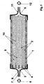
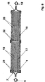
- Membrane module is the fluid to be treated in the outside the hollow fiber membranes initiated.
- the outlet device is located expediently in this case in the range of second end of the hollow fiber membranes, i.e. on the potting compound opposite end of the housing. This flows through Treating fluid as the primary stream the outside space around the hollow fiber membranes essentially along the length of the Hollow fiber membranes towards the outlet device. In these cases is due to the exterior around the hollow fiber membranes formed a channel system for the primary current.
- Part of the primary flow essentially flows through the pressure gradient over the entire extent of the hollow fiber membranes as permeate through their semipermeable, porous wall. This is done the substance-specific treatment on this partial flow. Subsequently the substream treated specifically for the substance enters the lumens of the hollow fiber membranes, which are used here as a collecting space for serve the permeate. The lumens or the collecting space leaves the Permeate flow through the openings at the second end of the hollow fiber membranes and unites with the one flowing through the channel system Primary stream, before that of primary stream and permeate combined stream as treated fluid via the outlet device is discharged from the housing.
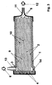
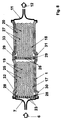
- Membrane module stands the at least one inlet device also in connection with a distribution room, the is adjacent to the potting compound and by the potting compound is spatially separated from the outside.
- the fluid to be treated flows as a primary stream over the inlet device of the housing in the distribution room and from this into the lumens of the hollow fiber membranes, flows through them in their longitudinal extension and leaves them through their opening on second, not embedded end of the hollow fiber membranes.
- the Primary current flows through the hollow fiber membranes on the lumen side, in which case the entirety of the lumens of the hollow fiber membranes train the duct system for the primary current.
- the partial flow treated in a substance-specific manner enters the hollow fiber membranes surrounding exterior from that in this embodiment serves as a collecting space for the permeate.
- This outside space flows through the permeate stream in the direction of the outlet device of the housing and unites in the outside space within the housing with that from the duct system, i.e. the primary stream flowing out.
- the treated fluid, i.e. the fluid flow combined from primary flow and permeate becomes derived from the housing via the outlet device.
- the outlet device are in different positions along the housing, however, it is preferably in the vicinity of the sealing compound.
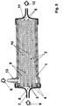
- the inventive Membrane module at least one inlet device, which opens into the outside space and is adjacent to the casting compound, and at least one inlet device connected to a distribution space is connected, the face of the potting compound adjacent is and due to the potting compound spatially from the outside is separated, this distribution space with the lumens of Hollow fiber membranes related to their first End through the potting compound and at this end are open.
- This makes it possible, in particular, in turns a fluid as the primary flow on the lumen side through the hollow fiber membranes and a fluid as a primary flow on the outside to let the outside flow.
- one Fluids for removing certain target substances contained in the fluid e.g. via adsorption to suitable groups in the Membrane first the fluid to be treated as the primary flow Flow through the hollow fiber membranes on the lumen side, as described a partial flow as permeate the walls of the hollow fiber membranes Flows through from the inside out. After completion of the substance-specific treatment can then be used to elute the Membranes adsorbed target substances as an elution fluid Primary flow flows around the outside of the hollow fiber membranes, whereby a partial flow as permeate the walls of the hollow fiber membranes Flows through to the inside and absorbs the target substances.
- the reverse driving style is also possible, i.e. Introducing the fluid to be treated into the exterior and then introducing the elution fluid into the lumens of the Hollow fiber membranes.
- Such an embodiment, in which the first alternate Fluid as primary flow on one side of the hollow fiber membranes and then another fluid as the primary stream on the can flow to the other side of the hollow fiber membrane can be advantageous also in the substance-specific treatment of suspensions use if there are particles in the suspension settle in or on the pore structure of the hollow fiber membranes can.
- the first step in the process is the primary current in the membrane module according to the invention to the introduced one side of the hollow fiber membranes, with the Permeate flow particles of appropriate size in the pore structure washed in or washed onto the pore structure of the membrane can be.
- the primary flow or a second fluid to the other Side of the hollow fiber membranes initiated as a primary stream, and it is formed due to the prevailing pressure conditions Permeate stream, which is compared to the permeate stream in the first process step the walls of the hollow fiber membranes in reverse Direction flows through and the membrane structure of the previous washed-in or washed-up particles. It can second fluid also elution liquid for in the first Process step also retained in the membrane structure be further target substances.
- the aim is that as high a proportion of their per hollow fiber membrane total volume of semi-permeable defined by its outer contour porous membrane wall, in which the substance-specific Treatment can be done.
- the one flowing through the semipermeable walls of the hollow fiber membranes Permeate flow through along the hollow fiber membranes determines the primary flow generated pressure gradient dp / dx.
- dp is the differential pressure change along a differential Distance dx in the direction of the primary current.
- the pressure drop in the direction of the longitudinal extension a hollow fiber membrane, i.e. along that of the primary current flow through channel system takes place with increasing throughput the channel system, i.e. with increasing primary current.
- the amount of the pressure drop dp / dx also increases the smaller are the flow cross sections of the channels from which the channel system flowed through by the primary current, i.e. so the smaller - depending on the embodiment - the cross section the lumens or the spaces between the hollow fiber membranes and between hollow fiber membranes and the inner wall of the housing is.
- the channels of the channel system arise in connection with suitable throughputs through the or flow velocities sufficiently high pressure gradients in the duct system to diffusive transport through the porous membrane structure much larger convective transport due to the permeate flow to overlay.
- the cross sections of the channels should not be too small so that - such as in the substance-specific treatment of suspensions, the one to be treated Fluid can still flow freely through the channels.
- Hollow fiber membranes are preferred in the membrane module according to the invention used, whose walls are essentially one have uniform thickness. In this way it is also achieved that the permeate flow when flowing through the membrane essentially the same at every point of a hollow fiber membrane Flow paths cover what is possible with regard to one uniform residence time of the fluid to be treated is particularly important Advantage is.
- the bundled hollow fiber membranes spaced from each other by spacers be so that there is an outer space around the hollow fiber membranes with defined gaps between the hollow fiber membranes formed. This ensures an even flow of the individual hollow fiber membranes of the bundle.
- the hollow fiber membranes through the primary flow through the spacers the size of the flow cross-sections of the channels of the Adjust hollow fiber membranes surrounding channel system, with what Influence on the pressure gradient occurring in the channels can be taken.
- a spacer is also used in the exterior Adaptation to the size of those contained in the suspension Allows particles.
- the spacers are expediently designed such that they have an elastic component.
- This can be a such bundle of hollow fiber membranes in a simple manner in the Housing of the membrane module can be introduced by first is slightly compressed, the distance between the hollow fiber membranes is slightly reduced in the housing is inserted and then relaxed, which causes the distance between the hollow fiber membranes increases again. As a result, the bundle of hollow fiber membranes is achieved abuts on the outer circumference of the housing inner wall, and an undesirable edge flow along the inside wall of the housing is avoided.
- the hollow fiber membranes within a bundle are preferred kept at a distance by textile threads. In principle, it is enough it, the textile threads between the hollow fiber membranes to lay.
- the hollow fiber membranes are preferred by means of the spacers in at least one hollow fiber mat involved, with these spacers especially is preferably textile threads.
- Such hollow fiber mats can advantageously be used as a knitted mat by known methods, Weaving mat or ribbon, but also as a knitting or as Make a crochet mat.
- weaving or knitting are the textile threads that run across the hollow fiber membranes running weaving or warp threads. Through these cross threads the hollow fiber membranes advantageously against each other evenly spaced and essentially within the mats arranged parallel to each other.
- Mats can be made up of bundles of hollow fiber membranes, which have a high order and in which between the Hollow fiber membranes formed a uniform channel system can be.
- the membrane module according to the invention are the hollow fiber membranes by means of flat, preferably strip-shaped connecting elements in the respective Hollow fiber mat integrated, these strip-shaped connecting elements act as a spacer at the same time.
- Such strip-shaped connecting elements can cross, however also at a different angle to each other advantageously essentially parallel hollow fiber membranes run and are point-like, for example applied adhesive e.g. based on polyurethane on laminated.
- Such mats of hollow fiber membranes are preferably used a stack or a bundle of individual in width layered according to dimensioned mat layers.
- the Hollow fiber membrane mats can, however, also advantageously have one layer or stacked on top of each other in a zig-zag shape Stack or folded into a bundle.
- the individual Windings or the individual layers expediently kept apart from each other, e.g. by means of the woven or knitted threads or inserted connecting elements and optionally by means of additional between the individual Spacers in the form of winding layers of fluid-permeable nonwovens or fabrics.
- Another advantageous embodiment are bundles that consist of at least two superimposed hollow fiber mats, in which the hollow fiber membranes within each mat in a mutual Spaced from each other by spiral Wrapping around an axis or core has been made are, the hollow fiber mats are superimposed so that the hollow threads of the superimposed hollow fiber mats in an intersecting arrangement are brought.
- the production such a bundle is described in detail in EP-A-0 285 812 described.
- the can be between the intersecting angles forming hollow fiber membranes are between 0 ° and 120 °, angles have been found to be favorable exposed between 30 ° and 90 °.
- the in the hollow fiber membrane bundle contained in the membrane modules according to the invention from core bundles arranged around a supporting thread Contain hollow fiber membranes, the one around the support thread arranged hollow fiber membranes with at least one winding thread are wrapped.
- the support threads in the Core bundles contain hollow fiber membranes at a distance from each other held.
- the winding threads ensure one Spacing of the hollow fiber membrane bundle Core bundles with each other, so that overall a good flow around of the hollow fiber membranes contained in the hollow fiber membrane bundle is guaranteed.
- Such composed of core bundles Hollow fiber membrane bundles are described in EP-A-0 732 141.
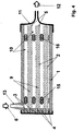
- steps b) and c) of the invention Be repeated several times. This leaves can be achieved in that in the housing in the direction of the longitudinal extent of the hollow fiber membranes several hollow fiber membrane bundles are arranged as steps in a row. Such a series connection of several levels is appropriate Design of the housing and the transitions between the individual Levels both in embodiments of the membrane module possible in which the primary flow through the lumens of the hollow fiber membranes is conducted, as well as in embodiments, at which the primary current the outer space around the hollow fiber membranes flows through.
- the length of the individual step can be i.e. in its dimension in the direction of the longitudinal extension of the in their contained hollow fiber membranes kept short and thereby a change in concentration with regard to possible critical Components in the fluid to be treated can be avoided.
- This is particularly substance-specific in such processes
- Treatment of suspensions of importance in which at least part of the suspended particles through the semipermeable Membrane wall of the hollow fiber membranes is to be retained and at the same time too high concentrations of suspended Particles should be avoided, e.g. in the substance-specific treatment of blood.
- comparative short hollow fiber membranes will run along the hollow fiber membranes only a small partial flow was withdrawn from the primary flow, so that the Concentration changes until the following merge of Primary and permeate flow remain low.
- the number is preferably in the membrane module according to the invention the steps in the housing between 1 and 100.
- Well proven has a number of steps between 1 and 10. It is advantageous if the individual stages are spaced apart to neither the primary stream nor the permeate stream locally by following in the flow direction of the housing order to impede the level and to ensure thorough mixing of primary flow and permeate flow.
- a uniform mixing is an advantage, e.g. undesirable Avoid fluctuations in concentration.
- the fluid to be treated recirculates and goes through the treatment process several times until a desired one Degree of treatment is reached.
- Hollow fiber membranes with different outer contours ie with different outer contours when viewed in cross section, can be used.
- the hollow fiber membranes can, for example, have an essentially round or circular, triangular, quadrangular, hexagonal or octagonal contour, they can also be oval, elliptical, three-lobed, four-lobed, etc.
- hollow fiber membranes with a wall thickness between 15 ⁇ m and 1500 ⁇ m have proven successful; hollow fiber membranes with a wall thickness between 100 ⁇ m and 300 ⁇ m have proven to be very effective.
- a and U denote the sum of the areas or circumferences of the individual lumens of the respective hollow fiber membrane. Hollow fiber membranes with a hydraulic diameter between 200 ⁇ m and 400 ⁇ m are particularly preferred.
- the ranges given above with regard to the hydraulic diameter apply analogously to the cross sections of the channels of the channel system formed by the outer space around the hollow fiber membranes.
- the hydraulic diameter d h of the hollow fiber membranes is preferably 1.2 to 12 times smaller than the hydraulic diameter d h1 of the channels.
- the permeate stream flows through the semipermeable wall of the hollow fiber membranes and convectively transports the target substance through the membrane.
- the semipermeable, porous wall of the hollow fiber membranes has a pore size that is convective Permits transport of the target substance through the membrane wall.
- the permeate flow is of course maximized if the average pore size of the membranes is maximized.
- the pore size must also match the size of the Target substance that is in the form of dissolved macromolecules, but also in the form of small particles with a particle size can be in the sub-micrometer range.
- the membrane separating function and contained in the suspension Holds back components that are not target substances.
- the pore size has a certain maximum value must not exceed. This can block the pore system or for example undesirable interactions between such restrained components with Interaction with the target substances provided Prevents substance-specific groups in the membrane become.
- the membrane module according to the invention may be with regard to the following applications of the membrane module according to the invention or embodiments of the method according to the invention rather be important to use membranes with the smallest possible pore sizes and the largest possible pore volume or the greatest possible porosity to be used in order to achieve a the largest possible inner, i.e. surface formed by the pores to provide the membrane.
- the hollow fiber membranes used according to the invention are medium Porosity between 50 vol.% And 90 vol.%.
- As a middle one Porosity becomes the ratio of the pore volume of the hollow fiber membrane understood the wall volume of the hollow fiber membrane, where the wall volume is made up of the pore volume and the volume of the material making up the membrane structure.
- the requirements for the construction of the hollow fiber membrane i.e. on their structure and pore size distribution over the wall thickness result from the respective application of the substance-specific Treatment.
- the membrane structure can over the wall thickness be isotropic, i.e. inside the membrane wall are the pore diameters essentially constant, they can be anisotropic, be symmetrical or asymmetrical, and the membrane can on one side a layer with a much denser pore structure, i.e. have skin.
- the denser layer can be the primary current or membrane but facing the collection room for the permeate.
- Suspensions may be required to achieve the membrane a small pore diameter for a certain separation effect the side facing the primary current.
- the membrane wall obtained, but the rest of the membrane structure is expedient coarser, but depending on the application not too coarse, in order to achieve the largest possible inner surface.
- Hollow fiber membranes with an average pore diameter are preferred between 0.005 and 5 ⁇ m, particularly preferably those with an average pore diameter between 0.1 and 3 ⁇ m used.
- anisotropic membranes e.g. a layer with denser Pore structure are used to determine the mean Pore diameter within the denser layer also the cited determination methods based on filtration experiments used.
- the Hollow fiber membranes in their wall covering at least 80% of the Wall thickness an essentially constant mean pore diameter exhibit. This allows a high inner Surface combined with a large number of immobilized, substance-specific groups in the membrane at the same time low pressure loss when flowing through the membrane wall and thus achieve a high permeate flow. As an im becomes a substantially constant mean pore diameter understood those who are no longer concerned about the wall thickness changes as +/- 50%.
- Porous hollow fiber membranes with a large inner surface are preferably used in the membrane module according to the invention or for carrying out the method according to the invention.
- Hollow fiber membranes with a BET surface area between 2 and 300 m 2 per cm 3 wall volume have proven themselves, hollow fiber membranes with a BET surface area between 8 and 30 m 2 per cm 3 wall volume have proven themselves.
- the BET method for determining the surface of porous membrane structures which is based on nitrogen adsorption measurement, is described by K. Kaneko, J. Membrane Science 96 (1994), 59-89.
- Membranes made of inorganic materials such as glass, ceramic, SiO 2 , carbon or metal, organic polymers or mixtures thereof can be used.
- the polymers can have a hydrophilic and / or hydrophobic character, they can be selected from the group of cellulosic polymers, such as cellulose or regenerated cellulose, modified cellulose, such as cellulose esters, cellulose ethers, amine-modified celluloses, and mixtures of cellulosic polymers from the group synthetic polymers such as polyacrylonitrile and corresponding copolymers, polyurethane-containing polymers, polyarylsulfones and polyaryl ether sulfones, such as polysulfone or polyethersulfone, polyvinylidene fluoride, polytetrafluoroethylene, water-insoluble polyvinyl alcohols, aliphatic and aromatic polyamides, polyimides, polyetherimides
- polymers such as polyethylene oxide, polyhydroxy ether, polyethylene glycol, polyvinyl pyrrolidone, polyvinyl alcohol or polycaprolactone, or inorganic substances such as SiO 2, for example, can be added to these polymers or polymer mixtures.
- the membrane can also have been subjected to a surface modification, for example, in order to adjust certain properties of the membrane surface, for example in the form of certain functional groups. If polyolefinic polymers are used, it may be necessary to coat at least the inner surface of the membrane, for example with a functionalizable polymer.
- cellulosic membranes Polymers, polyamides, polypropylene, polyether sulfones or made from solvent-stable and pH-stable polymers, especially with membranes made of polytetrafluoroethylene or polyvinylidene fluoride, and modifications derived therefrom, Blends, blends or copolymers.
- membranes are described for example in DE-A-39 23 128.
- the inner cross section is expediently to the particular use of the invention Membrane module or to the contour of those contained in the housing Adjusted bundle.
- housings with a square, rectangular, hexagonal, octagonal or also round inner cross section used.
- the hollow fiber membrane bundles which are preferred Have spacers with an elastic component, under a little compression and relaxation positioned in the housing. Then the hollow fiber membranes according to methods known per se on their first End embedded in a sealing compound in a fluid-tight manner in the housing.
- the housings are in one preferred embodiment has an inner cross section on the along the hollow fiber membranes towards the second Tapered end, i.e. the cross-sectional area of the housing decreases in this direction. This will make the distance between the hollow fiber membranes towards their second, not embedded end reduced and the pressure drop and thus the Permeate flow increased. At the same time, it can be used to equalize of the permeate stream over the longitudinal extent of the Achieve hollow fiber membranes.
- the membrane module according to the invention or the inventive The process can lead to a wide variety of substance-specific treatments of fluids are used.
- fluids to be treated suspensions are preferred.
- Particularly good ones Treatment results are achieved when the method according to the invention the membrane module according to the invention is used, being on and / or in the hollow fiber membranes preferably substance-specific groups are immobilized.
- too different substance-specific groups on and / or be immobilized in the hollow fiber membranes that are specific with various contained in the fluid to be treated Interact with target substances.
- too different hollow fiber membranes with different ones substance-specific groups can be used together.
- membrane modules with several stages in the hollow fiber membranes of the individual stages are the same, however also different substance-specific groups be immobilized.
- these substance-specific groups can be adsorptive or coupled to the membrane via covalent bonds.
- This coupling to the membrane can be done both before installation in the housing as well as after inserting the membrane into the housing of the membrane module according to the invention take place. You can do this in coordination depending on the respective application acting groups, for example, essentially homogeneous to the entire surface of the porous membrane, i.e. both to the outer, facing the lumens and the outer space Surfaces, as well as on the inner, formed by the pores Surfaces coupled, i.e. immobilized on and in the membrane his. But it may also be necessary that the groups acting on specific substances only on a part of them Surfaces are immobilized, for example when individual components of the fluid to be treated is not specific to the substance active groups should come into contact.
- substance-specific groups in the membrane matrix are possible in the case of membranes polymeric materials, for example by modifying the polymer material with, for example, ionic, hydrophilic or hydrophobic groups or by using polymer blends which at least one polymer component is substance-specific has active groups.
- Another option is there in such substance-specific groups or carrier substances or particles having such groups in the pore system of a membrane in the manufacturing process of Store the membrane or add it to the finished membrane e.g. cooperateschwemmen.
- the membrane has expediently an asymmetrical structure and optionally a skin, the openings of the skin or the Pores of the more porous side of the membrane are dimensioned so that the substance-specific groups or the named carrier substances or particles cannot pass through.
- the pore size of the membrane used is too large choose that even despite being immobilized in the pores substance-specific groups, the target substances convectively of at least a portion of the fluid to be treated through the Membrane wall can be transported.
- Ligands for the affine separation of ligates from those to be treated Liquids or around catalysts, taking catalysts also biocatalysts such as Enzymes are to be understood.
- preferred Processes according to the invention are purification / separation processes ligates from a ligate-containing liquid, wherein hollow fiber membranes are selected on and / or in which Ligands for said ligates are immobilized, or membrane modules according to the invention are used, the such Contain hollow fiber membranes.
- ligands can, depending on the application act non-specifically, group-specifically or specifically.
- Possibilities for their immobilization are explained in the explanations in European patent application EP 787 523 referred to, the disclosure of which was expressly referred to here becomes.
- the membrane module according to the invention or the inventive Process is for numerous cleaning / separation applications of ligates from a ligate-containing liquid, such as they, for example, generally from the area of affinity chromatography are known, taking affinity chromatography biospecific adsorption or also ion exchange chromatography or metal chelate chromatography be understood.
- liquids can be hollow fiber membranes be selected on and / or in which according to itself known methods immobilized enzymes or catalysts are.
- membrane module according to the invention or the method according to the invention catalytic treatments is again based on the explanations in European patent application EP 787 523 referred to, the disclosure of which was expressly referred to here becomes.
- the spacers located between the hollow fiber membranes can do other than the spacer function itself Perform functions. So - except on and / or in the porous membrane wall of the hollow fiber membranes also substance-specific active groups immobilized on the spacers his.
- the spacers are advantageous for this purpose from the same polymer or the same polymer family as the membrane material.
- Especially for between the mats spacers inserted from hollow fiber membranes have proven textile fabrics, such as those e.g. by Y. Yang et al., J. Chromatographie 598 (1992), 169-180. there guide fabrics with multifilament threads with a single thread diameter between 1 ⁇ m and 30 ⁇ m for particularly good results. Fabrics that both the weft and also the warp threads at an angle to the direction of the primary current have a value between 30 ° and 60 ° having.
- Figure 1 shows a membrane module according to the invention with a Housing 1, which contains hollow fiber membranes 2 arranged as a bundle.
- the hollow fiber membranes 2 are 3 in at one end a potting compound 4 embedded and at its second end 5 in a fluid can flow around it essentially free.
- the fluid to be treated is passed through the inlet device 7 into the distribution space 8, towards which the hollow fiber membranes 2 with their embedded End 3 are open.
- Fluid as primary flow in the lumens 9 of the hollow fiber membranes 2 initiated and flows through the hollow fiber membranes towards their non-embedded end 5. Because of the pressure drop arising during the flow through the lumens flows along the hollow fiber membranes 2 a part of the primary current as a permeate flow through the porous semipermeable wall of the Hollow fiber membranes 2 in the surrounding the hollow fiber membranes Outside space 10, the partial flow flowing through the wall being a undergoes substance-specific treatment.
- the substance-specific treated permeate is collected in the exterior 10 and flows through it in the direction of the outlet device 11, which is in the area of the non-embedded ends 5 of the Hollow fiber membranes 2 with the flowing out of the lumens 9 Primary stream combined.
- the one made up of primary stream and permeate Fluid flow leaves the membrane module as treated fluid 12 via the outlet device 11 which in the case of FIG membrane module shown at the non-embedded ends 5 of the hollow fiber membranes 2 facing the end of the housing 1 is arranged.
- the arrangement of the outlet device on the non-embedded Ends 5 of the hollow fiber membranes 2 facing the end of the housing 1 represents only one of several possibilities. As shown in FIG. 2, preference is given to the case of lumen-side supply of the primary current according to FIG. 1, the outlet device 11 adjacent to the potting compound 4 and thus towards the first, embedded ends 3 of the hollow fiber membranes 2 arranged. In this case also flows through Primary flow after exiting the lumens 9 of the hollow fiber membranes 2 at their non-embedded ends 5 the directly the hollow fiber membranes 2 surrounding outer space 10 and leaves, mixed with that also flowing through the outer space 10 Permeate flow as treated fluid 12, the housing 1 over the Outlet device 11.
- a membrane module is shown in which the one Bundle of hollow fiber membranes 2 outside of Flow around primary current.
- the housing 1 at the level of the inlet device 13 an extension 14 of the diameter to a more uniform Distribution of the fluid to be treated as a primary flow to reach across the entire bundle cross-section.
- the first Ends 3 of the hollow fiber membranes 2 are in this embodiment embedded in the sealing compound 4 so that the lumens 9 by means of the sealing compound 4 are closed at this end.
- the fluid 6 to be treated flows through the inlet device 13 into and into the outer space 10 surrounding the hollow fiber membranes 2 flows through this outer space 10 as a primary flow essentially along the hollow fiber membranes 2 towards the outlet device 11. Due to the pressure drop that occurs Permeate flow essentially over the entire extent of the Hollow fiber membrane bundle through the semi-permeable, porous walls the hollow fiber membranes 2 in their lumens 9. On which the Walls of the hollow fiber membranes 2 flowing permeate stream takes place the substance-specific treatment.
- the treated permeate stream leaves the lumens 9 through the openings on the second End 5 of the hollow fiber membranes 2 and unites there in the outer space 10 with the primary current before the primary current and Permeate combined stream as treated fluid 12 via the outlet device 11 is discharged from the housing 1.
- a membrane module of the type shown in Figure 3 in which the hollow fiber membranes arranged in a bundle on the outside are surrounded by the primary current, it is important for one even distribution of the fluid to be treated over the bundle cross-section to care. In principle, this can be achieved be that when flowing through the outside space or the duct system formed by the exterior Flow resistance is sufficiently high, such as through Introducing elements into this outdoor space for an increase the flow resistance.
- Figure 4 are - in Flow direction between inlet device 13 and outlet device 11 seen - tubular or capillary-shaped elements 15 introduced into the outer space 10 around the hollow fiber membranes 2, for an increase in flow resistance in the inlet device 13 adjacent part of the outdoor space 10 and so an equalization of the distribution of the primary current cause.
- the membrane module shown in FIG. 4 also includes in the area of the non-embedded ends 5 of the hollow fiber membranes 2 additional flow resistance increasing elements 16 introduced into the outer space 10.
- additional flow resistance increasing elements 16 introduced into the outer space 10.
- tubular or capillary Elements 16 can be the flow resistance for the Primary current when flowing through the outside space results, increase and in this way the permeate flow through the walls enlarge the hollow fiber membranes.
- tubular or capillary elements instead of tubular or capillary elements
- other flow resistance increasing Elements are used, for example in Form of appropriately designed fluid-permeable spacers or in the form of fluid-permeable nonwovens, for example for hollow fiber membrane bundles that consist of a spiral around one Core-wound hollow fiber membrane mats are formed, placed in strips between the layers created during winding become.
- FIG. 5 shows a membrane module according to the invention, which both has an inlet device 7 with a distribution space 8 and over this with the lumens 9 of the hollow fiber membranes 2 in Connected, as well as an inlet device 13, which in the outer space 10 surrounding the hollow fiber membranes 2 opens and is adjacent to the sealing compound 4.
- the membrane module according to the invention can different fluids alternating as primary flow on the lumen side through the hollow fiber membranes and outside through the Outside space.
- a specific one to be treated can first be treated Fluid containing target substances via the inlet device 7 introduced as a primary flow into the lumens 9 of the hollow fiber membranes 2 are closed, the inlet device 13 remains.
- a permeate stream is formed in the manner already described through the semi-permeable, porous walls of the hollow fiber membranes 2, and there is a substance-specific treatment of the permeate stream, for example, by adsorption of the target substances in the hollow fiber membranes 2 and thus a loading of the hollow fiber membranes 2 with the target substances.
- the one around the target substances impoverished permeate stream is combined with that from the lumens 9 of the hollow fiber membranes 2 emerging primary stream over the Outlet device 11 derived from the housing 1.
- the target substances in a simple way out of the hollow fiber membranes be eluted by adding an elution liquid via the inlet device 13 is introduced into the exterior 10 and the Elution liquid flows through the outer space as the primary stream.
- the inlet device 7 remains closed. Then occurs in the manner already described a permeate flow through the semipermeable porous walls of the Hollow fiber membranes 2, but in the opposite direction as when loading the hollow fiber membranes with the target substances, and elution of the target substances from the Hollow fiber membranes 2 take place.
- FIG. 6 shows a membrane module according to the invention, of the two hollow fiber membrane bundles arranged one behind the other as steps 17, 18 contains the hollow fiber membranes 19, 20 each embedded at one end in casting compounds 21, 22 are.
- the fluid 6 to be treated is via the inlet device 7 introduced into the housing 1 of the membrane module and first flows through the hollow fiber membranes as the primary flow on the lumen side 19 of the first membrane bundle 17.
- the resultant Permeate flow is in the walls of the hollow fiber membranes 19th undergo a first substance-specific treatment.
- the outside space in the area of the first membrane bundle 17th permeate flow flowing through combines in the area of non-embedded ends of the hollow fiber membranes 19 of the membrane bundle 17 with that from the lumens of the hollow fiber membranes 19 emerging primary current, and the resulting current of the simple treated fluid then comes again on the lumen side as primary current in the hollow fiber membranes 20 of the second membrane bundle 18 a.
- the processes are repeated in the area of the first Membrane bundle 17 took place, and in the walls of the hollow fiber membranes 20 of the second bundle 18 takes place on it permeate stream flowing through another substance-specific treatment.
- the fluid stream 12 thus treated twice is about the outlet device 11 is discharged from the membrane module. How executed, can in the hollow fiber membranes of each Levels of immobilized, substance-specific groups too be different so that a fluid to be treated when Flow through a membrane module containing several stages experienced several different substance-specific treatments can.
- FIG. 7 A possibility of connecting several bundles in series of hollow fiber membranes as steps with outside flow the hollow fiber membranes through the primary flow is shown in FIG. 7 shown.
- the fluid to be treated is - as with examples for flow through the primary current on the lumen side - front, i.e. from the embedded ends of the hollow fiber membranes forth, via the inlet device 7 in the before the first stage arranged distribution room 8 directed.
- the distribution room 8 borders on one side of the potting compound 23, by means of of which the hollow fiber membranes 19 of the bundle 17 of the first stage embedded at its end facing the inlet device are that their lumens are closed at these ends.
- these potting compound 23 are also fluid-permeable elements 24 embedded, which in the case shown as tubes or capillaries are trained.
- the fluid to be treated is the primary flow in the Outside space 25 around the hollow fiber membranes 19 of the first membrane bundle 17 headed. As described flows due to the prevailing Pressure conditions a permeate flow through the semipermeable, porous walls of the hollow fiber membranes 19 and there undergo a first substance-specific treatment. In the area the non-embedded ends of the hollow fiber membranes 19 the primary flow combines with the permeate flow in the outside 25th
- the resultant first substance-specific treatment fluid stream undergoes bundle 18 in the second stage the hollow fiber membranes 20 supplied.
- This level is analogous to first stage executed.
- the sealing compound 26 fluid-permeable elements 24, by means of which the other fluid to be subjected to in the substance-specific treatment Outside space 27 around the hollow fiber membranes 20 of the second bundle 18 is directed.
- the processes taking place here correspond those in the first stage, the permeate stream being the second stage subjected to a further substance-specific treatment becomes.
- the fluid stream 12 then treated twice becomes then passed through the outlet device 11 from the membrane module.
- FIG. 8 A modification of the membrane module shown in Figure 7 with two hollow fiber membrane bundles arranged one behind the other as steps 17.18 and outside flow around the hollow fiber membranes 19, 20 through the primary current is shown in FIG. 8. at the membrane module according to FIG. 8 is initiated treating fluid 6 also via the inlet device 7. The primary current is then from the front, i.e. of the Level forth, each by the potting compound 23.26 and the embedded, ends of the sealing compound 23, 26 closed Hollow fiber membranes 19, 20 is formed in the respective outer space 25.27 passed around the hollow fiber membranes.
- the housing 1 Around the embedded ends of the hollow fiber membranes 19, 20 of the respective Bundles 17, 18 around are fluid-permeable in the form of a ring Elements 28.29 embedded in the casting compounds 23.26, which in the shown example formed as short tubes or capillaries are and which pass through the casting compounds 23, 26.
- the housing 1 In the area of the casting compounds 23, 26, the housing 1 has extensions 30.31 with respect to its inner diameter. hereby on the one hand, a uniform supply of the to be treated Fluids to the fluid-permeable elements 28.29 reached. To the others are 30.31 ring channels 32.33 through these extensions formed behind the casting compounds 23, 26 in the direction of flow, into which the fluid-permeable elements 28, 29 open and through which an even distribution of the primary current over the respective Bundle cross section is reached.
Abstract
Description
Die Erfindung betrifft einen Membranmodul zur stoffspezifischen
Behandlung eines Fluids, enthaltend
Stoffspezifische Behandlungen von Fluiden gewinnen in zunehmendem Maße an Bedeutung in Anwendungsgebieten wie der Biotechnologie, der Medizin oder der chemischen Technologie. Unter Fluiden sind dabei Gase, Gasgemische sowie allgemein Flüssigkeiten wie z.B. Proteinlösungen, vorfiltrierte Suspensionen oder klare Lösungen zu subsummieren. Ein Beispiel für eine stoffspezifische Behandlung ist die Gewinnung von Wirkstoffen aus Zellsuspensionen, in denen genmodifizierte Zellen Stoffe wie Antikörper, Hormone, Wachstumsfaktoren oder Enzyme in meist kleinen Konzentrationen produziert haben. Eine wichtige Anwendung ist auch die extrakorporale Entfernung von unerwünschten Substanzen aus dem menschlichen Blutplasma sowie die Gewinnung von Komponenten wie z.B. Immunglobulinen oder Gerinnungsfaktoren aus gespendetem Blutplasma. Schließlich ist eine breite Anwendung auch die katalytische oder biokatalytische - enzymatische - Behandlung von Flüssigkeiten wie z.B. die Hydrolyse von Ölen durch Lipasen, die an einer Matrix immobilisiert sind.Substance-specific treatments for fluids are increasing Degree of importance in application areas such as biotechnology, medicine or chemical technology. Under fluids are gases, gas mixtures and generally liquids such as. Protein solutions, pre-filtered suspensions or clear Subsume solutions. An example of a substance specific Treatment is the extraction of active substances from cell suspensions, in which genetically modified cells substances such as antibodies, Hormones, growth factors or enzymes in mostly small ones Have produced concentrations. An important application is also the extracorporeal removal of unwanted substances from human blood plasma and the extraction of components such as. Immunoglobulins or coagulation factors from donated Blood plasma. After all, it is widely used also catalytic or biocatalytic - enzymatic - treatment of liquids such as the hydrolysis of oils by lipases immobilized on a matrix.
Die stoffspezifische Behandlung von Fluiden erfolgt vielfach derart, daß das zu behandelnde Fluid mit einem Trägermaterial in Kontakt gebracht wird, auf und/oder in dem wechselwirkende Gruppen oder Substanzen immobilisiert sind, die in spezifischer, selektiver Weise mit der in dem Fluid enthaltenen Zielsubstanz, d.h. der Substanz, auf die die stoffspezifische Behandlung ausgerichtet ist, wechselwirken. Solche Wechselwirkungen können beispielsweise Kationen- oder Anionenaustausch, Hydrophil-Hydrophob-Wechselwirkung, Wasserstoffbrückenbildung, Affinität oder enzymatische oder katalytische Reaktionen und dergleichen sein. Bei der affinen Stofftrennung, wie z.B. der Affinitätschromatographie, sind an das Trägermaterial Liganden gekoppelt oder im Trägermaterial immobilisiert, die die Funktion haben, eine einzelne Zielsubstanz oder auch eine ganze Klasse von Substanzen adsorptiv spezifisch zu binden. Diese Zielsubstanz wird als Ligat bezeichnet. Ein Beispiel für klassenspezifische Liganden sind positiv geladene Diethylaminoethyl(DEAE)-Gruppen oder negativ geladene Sulfonsäure(SO3)-Gruppen, die die Klasse der positiv geladenen bzw. negativ geladenen Moleküle adsorbieren. Spezifische Liganden sind z.B. Antikörper gegen ein bestimmtes Protein, das als Ligat an den Antikörper gebunden wird.The substance-specific treatment of fluids is often carried out in such a way that the fluid to be treated is brought into contact with a carrier material on and / or in which interacting groups or substances are immobilized in a specific, selective manner with the target substance contained in the fluid, ie interact with the substance to which the substance-specific treatment is aimed. Such interactions can be, for example, cation or anion exchange, hydrophilic-hydrophobic interaction, hydrogen bonding, affinity or enzymatic or catalytic reactions and the like. In the affine separation of substances, such as affinity chromatography, ligands are coupled or immobilized in the support material, which have the function of specifically binding an individual target substance or an entire class of substances by adsorption. This target substance is called a ligate. An example of class-specific ligands are positively charged diethylaminoethyl (DEAE) groups or negatively charged sulfonic acid (SO 3 ) groups, which adsorb the class of positively charged or negatively charged molecules. Specific ligands are, for example, antibodies against a specific protein which is bound to the antibody as a ligate.
Wesentliche Kriterien bei der stoffspezifischen Behandlung von Fluiden sind Produktivität und Selektivität. Mit Blick auf die Produktivität ist es wichtig, daß möglichst viele stoffspezifisch wirkende Gruppen pro Volumeneinheit zur Verfügung stehen, die mit der in dem zu behandelnden Fluid enthaltenen Zielsubstanz in Wechselwirkung treten können. Gleichzeitig ist eine Maximierung des Transports der Zielsubstanz zu den stoffspezifisch wirkenden Gruppen bzw. Substanzen anzustreben.Essential criteria for the substance-specific treatment of Fluids are productivity and selectivity. With view on Productivity, it is important that as many substance-specific active groups per volume unit are available, with the target substance contained in the fluid to be treated can interact. At the same time is one Maximizing the transport of the target substance to the substance-specific aiming at active groups or substances.
Ein in der Affinitätschromatographie häufig eingesetztes Trägermaterial für Liganden sind Sepharosepartikel, die in Form einer Schüttung in einer Chromatographiesäule vorliegen. Wenngleich sich hierbei eine hohe Konzentration an Liganden mit hoher Selektivität realisieren läßt, ist die Produktivität wegen der hohen Druckverluste der Partikelsäulen und der Kompressibilität der Sepharosepartikel bekanntermaßen gering. Darüberhinaus ist der Zugang der Ligaten zu den in den Sepharosepartikeln enthaltenen Liganden diffusionskontrolliert, wodurch insbesondere bei der Abtrennung von größeren Molekülen wie z.B. von Proteinen aufgrund geringer Diffusionsgeschwindigkeiten lange Verweilzeiten und damit nur geringe Durchsätze und geringe Produktivitäten resultieren.A carrier material often used in affinity chromatography for ligands are Sepharose particles, which are in the form a bed in a chromatography column. Although a high concentration of ligands with high Allowing selectivity to be achieved is due to productivity the high pressure losses of the particle columns and the compressibility the Sepharose particles are known to be low. Furthermore is the access of the ligates to those in the Sepharose particles contained ligands diffusion-controlled, whereby especially when separating larger molecules such as e.g. of proteins due to low diffusion rates long dwell times and therefore only low throughputs and low Productivities result.
Verbesserte Chromatographie-Säulenmaterialien aus starren, porösen Partikeln, die konvektiv durchströmt werden können, werden in der US-A-5 019 270 beschrieben. Diese Partikel erlauben gegenüber dem zuvor genannten Säulenmaterial eine Reduzierung der Verweilzeit und eine Steigerung der Produktivität. Dennoch weisen auch mit diesen Partikeln gefüllte Chromatographie-Säulen bei größeren Säulendurchmessern eine ungleichförmige Durchströmung auf, die sich negativ in bezug auf eine gleichmäßige Nutzung aller in der Chromatographiesäule vorhandenen Liganden auswirkt. Ferner wird die technische Beherrschung der erforderlichen Drücke mit größeren Durchmessern zunehmend aufwendiger.Improved chromatography column materials made of rigid, porous Particles that can be flowed through convectively in US-A-5 019 270. Allow these particles a reduction compared to the aforementioned column material the dwell time and an increase in productivity. Yet also have chromatography columns filled with these particles with larger column diameters a non-uniform Flow on, which is negative with respect to a uniform Use of all ligands present in the chromatography column effect. Furthermore, the technical mastery of the required pressures with larger diameters increasingly complex.
Die geschilderten Nachteile partikelförmiger Trägermaterialien führten zur Entwicklung einer Reihe von Verfahren zur stoffspezifischen Behandlung von Fluiden unter Verwendung von porösen, semipermeablen Membranen. Aufgrund ihrer porösen Struktur stellen Membranen eine große innere Oberfläche zur Verfügung, so daß an die Membranen in einer hohen Konzentration pro Volumeneinheit eine große Anzahl von funktionellen Gruppen gekoppelt werden kann, die in Wechselwirkung mit den die Membran durchströmenden, zu behandelnden Fluiden treten (s. z.B. E. Klein, "Affinity Membranes", John Wiley & Sons, Inc., 1991; S. Brandt u. a., "Membrane-Based Affinity Technology for Commercial Scale Purifications", Bio/Technology Vol. 6 (1988), S. 779-782).The described disadvantages of particulate carrier materials led to the development of a number of methods for substance-specific Treatment of fluids using porous, semipermeable membranes. Because of their porous structure Membranes have a large inner surface available, so that to the membranes in a high concentration per unit volume a large number of functional groups coupled in interaction with the flow through the membrane fluids to be treated occur (see e.g. E. Klein, "Affinity Membranes", John Wiley & Sons, Inc., 1991; S. Brandt u. a., "Membrane-Based Affinity Technology for Commercial Scale Purifications ", Bio / Technology Vol. 6 (1988), pp. 779-782).
Es stehen Membranen aus unterschiedlichsten Materialien und mit unterschiedlichen Porenstrukturen zur Verfügung, so daß eine Anpassung an die physikochemischen Eigenschaften der zu behandelnden Fluide und ein konvektiver Transport des zu behandelnden Fluids z.B. mit einer in ihm enthaltenen Zielsubstanz durch die Membran möglich ist. Darüberhinaus zeichnen sich Membranen aufgrund ihrer in der Regel nur geringen Wanddicke (z.B. <100 µm) durch kurze Transportwege des zu behandelnden Fluids z.B. zu in den Membranen immobilisierten, wechselwirkenden Gruppen aus, wodurch die Verweilzeiten vergleichsweise kurz, die Druckverluste gering, die linearen Flußgeschwindigkeiten und damit die Bindungsraten hoch sind.There are membranes made of different materials and with different pore structures available, so that a Adaptation to the physicochemical properties of the treatment Fluids and a convective transport of the to be treated Fluids e.g. with a target substance contained in it the membrane is possible. In addition, membranes stand out due to their usually only small wall thickness (e.g. <100 µm) due to short transport routes of the fluid to be treated e.g. to interacting groups immobilized in the membranes from, which makes the dwell times comparatively short, the Low pressure drops, the linear flow velocities and so that the binding rates are high.
Es sind eine Reihe von solche Membranen enthaltenden Modulen beschrieben, die bei Verfahren zur stoffspezifischen Behandlung von Fluiden verwendet werden. Dabei ist zwischen dem sogenannten dead-end-Modus bzw. den dead-end-Modulen und dem cross-flow-Modus bzw. den cross-flow-Modulen zu unterscheiden.There are a number of modules containing such membranes described in procedures for substance-specific treatment of fluids can be used. It is between the so-called dead-end mode or the dead-end modules and cross-flow mode or to distinguish the cross-flow modules.
Bei der Fahrweise im cross-flow-Modus fließt der Feedstrom parallel zur einen Seite der Membran. Dabei tritt ein Teil des Feedstroms durch die Membran hindurch. Der hindurchgetretene Teilstrom wird als Permeat, der auf der Feedstromseite verbleibende Teilstrom als Retentat abgeleitet. Hierbei kann auch auf der Permeatseite der Membran ein zusätzlicher Fluidstrom eingeleitet werden, der den durch die Membran hindurchgetretenen Teilstrom aufnimmt.When operating in cross-flow mode, the feed stream flows in parallel to one side of the membrane. Part of the Feed streams through the membrane. The one who stepped through Partial stream is called permeate, the one remaining on the feedstream side Partial stream derived as retentate. This can also an additional fluid flow on the permeate side of the membrane be introduced, the one that has passed through the membrane Partial stream picks up.
Beim dead-end-Modus hingegen wird das gesamte, als Feedstrom in den Membranmodul einströmende Fluid durch die Membran hindurchgeführt und auf der der Einströmseite der Membran gegenüberliegenden Abströmseite als Filtrat bzw. Permeat abgeleitet.In dead-end mode, on the other hand, the entire, as feed stream in fluid flowing in through the membrane module passes through the membrane and on the opposite side of the inflow side of the membrane Downstream side derived as filtrate or permeate.
Dead-end-Membranmodule auf Basis von Hohlfasermembranen werden vielfach für Anwendungen im Bereich der Ultra- oder Mikrofiltration und oftmals z.B. zur Begasung von Flüssigkeiten eingesetzt. Bei einem Teil dieser Membranmodule, wie sie z.B. in der EP-A-0 138 060 oder der EP-A-0 659 468 beschrieben werden, sind die Hohlfasermembranen U-förmig gebogen und ihre Enden gemeinsam in einer Vergußmasse eingebettet und geöffnet. Das Gas bzw. die zu filtrierende Flüssigkeit strömt beispielsweise über die offenen Enden in die Lumina der Hohlfasermembranen ein und permeiert aufgrund der anliegenden Druckdifferenz in den Außenraum um die Hohlfasermembranen. Bei Filtrationsanwendungen verbleibt dann die abfiltrierte Komponente in der Membran.Dead-end membrane modules based on hollow fiber membranes often for applications in the field of ultra or microfiltration and often e.g. used for fumigation of liquids. With some of these membrane modules, e.g. in the EP-A-0 138 060 or EP-A-0 659 468 the hollow fiber membranes bent into a U-shape and their ends together embedded in a potting compound and opened. The gas or the liquid to be filtered flows, for example, over the open ends in the lumens of the hollow fiber membranes and permeated due to the pressure difference in the outside space around the hollow fiber membranes. In filtration applications remains then the filtered component in the membrane.
In einer anderen Ausführung von dead-end Membranmodulen sind die Hohlfasermembranen im wesentlichen geradlinig im Gehäuse angeordnet und mit ihrem einen, geöffneten Ende gemeinsam in eine Vergußmasse eingebettet , wohingegen ihr zweites Ende frei, d.h. nicht eingebettet ist. Das nicht eingebettete Ende der Hohlfasermembranen ist bei diesen Modulen geschlossen. Derartige Membrarimodule sind beispielsweise in US-A-4 002 567, US-A-4 547 289, EP-A-0 138 060 oder EP-A-0 732 142 beschrieben.Another version of dead-end membrane modules are the hollow fiber membranes are essentially straight in the housing arranged and with their one, open end together in a potting compound embedded, whereas its second end free, i.e. is not embedded. The end not embedded the hollow fiber membranes are closed in these modules. such Membrane modules are, for example, in US-A-4 002 567, US-A-4 547 289, EP-A-0 138 060 or EP-A-0 732 142.
Bei allen dead-end-Membranmodulen ist von Nachteil, daß sie für die Behandlung z.B. von Suspensionen dann oft nicht geeignet sind, wenn die Größe der in der Suspension enthaltenen Teilchen in der Größenordnung der Porendurchmesser liegen. Die Teilchen würden zum Aufbau einer Schicht auf der Membranwand führen und die Membran blockieren. Für die Anwendung bei z.B. Affinitätstrennverfahren für Suspensionen können derartige dead-end-Module nur in Kombination mit einer vorgeschalteten Vorreinigungsstufe betrieben werden. Hierdurch verliert ein solches Verfahren jedoch an Effizienz, etwa auch dadurch, daß in vielen Fällen durch eine solche Vorreinigung ein Großteil der Zielsubstanz verloren geht.A disadvantage of all dead-end membrane modules is that they are suitable for the treatment e.g. of suspensions then often not suitable if the size of the particles contained in the suspension are in the order of the pore diameter. The particles would lead to the formation of a layer on the membrane wall and block the membrane. For use in e.g. Affinity separation process Such dead-end modules can be used for suspensions only in combination with an upstream pre-cleaning stage operate. This loses one However, the process is more efficient, for example in that in many A large part of the target substance is caused by such pre-cleaning get lost.
Die genannten Nachteile im dead-end-Modus betriebener Module in Bezug z.B. auf ihre Verwendbarkeit bei Suspensionen können zumindest teilweise bei Einsatz von cross-flow-Modulen vermieden werden. Bei diesen läßt sich durch den parallel zur Membranoberfläche strömenden Feedstrom bei genügend hohen Scherbeanspruchungen der Aufbau einer Schicht aus suspendierten Teilchen verringern.The disadvantages mentioned in dead-end mode operated modules in Reference e.g. on their usability in suspensions at least partially avoided when using cross-flow modules become. These can be parallel to the membrane surface flowing feed stream with sufficiently high shear stresses building a layer of suspended particles reduce.
Die WO 90/05018 offenbart einen cross-flow Modul mit Hohlfasermembranen zum Einsatz bei Affinitätstrennverfahren. Bei diesem wird eine ligathaltige Flüssigkeit über eine Einlaßeinrichtung in das Modulgehäuse eingeleitet und strömt tangential entlang einer Seite der Hohlfasermembranen, in und an der die Liganden gekoppelt sind. Ein Teil der Flüssigkeit permeiert durch die Membran hindurch, wobei die Ligaten an die Liganden angelagert werden, und tritt auf der der Eintrittsseite gegenüberliegenden Membranseite als Permeatstrom aus. Über getrennte Auslaßeinrichtungen werden Retentatstrom und Permeatstrom abgeleitet. WO 90/05018 discloses a cross-flow module with hollow fiber membranes for use in affinity separation processes. With this becomes a liquid containing ligate via an inlet device introduced into the module housing and flows tangentially along one side of the hollow fiber membranes, in and on which the Ligands are coupled. Part of the liquid permeates through the membrane, with the ligates attached to the ligands be deposited, and occurs on the opposite side of the entry side Membrane side as a permeate stream. About separate Outlet devices become retentate stream and permeate stream derived.
Eine Abwandlung eines cross-flow-Prozesses wird in der WO 93/02777 beschrieben. Zur spezifischen Entfernung von Komponenten aus dem Blut dient ein Plasmafilter aus U-förmig gebogenen und an ihren Enden in ein speziell ausgeformtes Gehäuse eingebetteten Hohlfasermembranen. Die Hohlfasermembranen werden lumenseitig vom Blut durchströmt, die stoffspezifische Behandlung erfolgt an dem mittels der Membran abgetrennten Blutplasma im Außenraum um die Hohlfasermembranen im Gehäuse, in dem sich ein Reinigungsmedium befindet. Das Bündel läßt sich in einen Einströmast und in einen Ausströmast unterteilen. Aufgrund des im Bereich des Einströmasts auftretenden positiven Transmembrandrucks erfolgt ein konvektiver Transport von Blutplasma durch die Membran in den Außenraum. Im Bereich des Ausströmasts strömt das behandelte Plasma aufgrund des dort auftretenden negativen Transmembrandrucks in das Lumen der Hohlfasermembranen zurück und wird wieder mit dem Blut vereinigt.A modification of a cross-flow process is described in WO 93/02777. For the specific removal of components a plasma filter made of U-shaped bends is used from the blood and embedded at their ends in a specially shaped housing Hollow fiber membranes. The hollow fiber membranes are on the lumen side with blood flowing, the substance-specific treatment takes place on the blood plasma separated in the membrane External space around the hollow fiber membranes in the housing, in which a Cleaning medium. The bundle can be divided into one Inflow branch and divide into an outflow branch. Because of the positive occurring in the area of the inflow branch Transmembrane pressure is a convective transport of blood plasma through the membrane into the outside space. In the area of the outflow branch flows the treated plasma due to the occurring there negative transmembrane pressure in the lumen of the hollow fiber membranes back and is reunited with the blood.
In der EP-A-0 341 413 wird ein Adsorbermodul zur Behandlung von Vollblut beschrieben, bei dem die im Modul enthaltenen, an ihren beiden Enden in Vergußmassen eingebetteten und mit Liganden versehenen Hohlfasermembranen im cross-flow-Modus lumenseitig vom Blut durchströmt werden. Hierbei tritt Plasma als Permeat durch die Hohlfasermembranwand in den die Hohlfasermembranen umschließenden Außenraum, wobei in der Membranwand die Behandlung des Plasmas erfolgt. In einer speziellen Ausführungsform besitzt dieser Modul keinen Auslaß für das Permeat, sondern das als Permeat abgetrennte Plasma sammelt sich im Außenraum um die Kapillaren und tritt infolge der sich einstellenden Druckverhältnisse wieder durch die Hohlfasermembranwandung in das Lumen der Hohlfasermembran ein. Aufgrunddessen, daß bei einem solchen Modulkonzept der Permeatstrom zweimal durch die Membranwand hindurchtreten muß, ist dieser Permeatstrom und damit der der stoffspezifischen Behandlung unterzogene Anteil des Plasmas relativ klein. Hieraus resultiert auch daß die erforderlichen Behandlungszeiten relativ lang sind.EP-A-0 341 413 describes an adsorber module for the treatment of Whole blood described, in which the contained in the module, on their both ends embedded in potting compounds and with ligands provided hollow fiber membranes in cross-flow mode on the lumen side are flooded with blood. Here, plasma occurs as a permeate through the hollow fiber membrane wall in which the hollow fiber membranes enclosing outside space, the in the membrane wall Treatment of the plasma is carried out. In a special embodiment this module has no outlet for the permeate, rather the plasma separated as permeate collects in the outside space around the capillaries and occurs as a result of the emerging Pressure conditions again through the hollow fiber membrane wall into the lumen of the hollow fiber membrane. Due to the fact that with such a module concept, the permeate flow through twice must pass through the membrane wall is this permeate stream and thus the portion subjected to the substance-specific treatment of the plasma is relatively small. This also means that the required Treatment times are relatively long.
Die beschriebenen, im cross-flow-Modus betriebenen Module weisen verschiedene Nachteile auf. So sind bei getrennten Permeatund Retentatströmen zusätzliche Pumpen und/oder Kontrollorgane erforderlich. Ferner sind die Module durch die beidseitige Einbettung der Hohlfasermembranen an deren Enden aufwendig in der Fertigung, und es nimmt aufgrund der Einbettungen bei geringeren Modullängen in steigendem Maße der Anteil der Membranen zu, der im Hinblick auf die stoffspezifische Behandlung ohne Funktion ist. Da bei cross-flow Modulen nur ein Teilstrom des insgesamt zu behandelnden Fluids durch die Membran geleitet wird, ist oft eine Hintereinanderschaltung mehrerer Module erforderlich. Dann erhöht sich jedoch der Aufwand für Fertigung und Betrieb der cross-flow Module nach dem Stand der Technik erheblich.The modules described, which are operated in cross-flow mode, show various disadvantages. So with separate permeate and Retentate flows additional pumps and / or control organs required. Furthermore, the modules are double-sided Embedding of the hollow fiber membranes at their ends is expensive manufacturing, and it increases due to the embedding shorter module lengths, the proportion of membranes increases to that in terms of substance-specific treatment has no function. Because with cross-flow modules only a partial flow of the total fluid to be treated passed through the membrane a series connection of several modules is often required. Then, however, the effort for manufacturing increases and operation of the cross-flow modules according to the state of the art considerably.
Es ist daher Aufgabe der Erfindung, einen Membranmodul der eingangs genannten Art zur stoffspezifischen Behandlung von Fluiden zur Verfügung zu stellen, bei dem die genannten Nachteile des Standes der Technik zumindest reduziert sind, der in einfacher Weise herstellbar ist, flexibel an die jeweilige Fluidbehandlung angepaßt werden kann und insbesondere auch für Suspensionen geeignet ist.It is therefore an object of the invention to provide a membrane module mentioned type for the substance-specific treatment of fluids to provide, in which the disadvantages mentioned of the prior art are at least reduced in simpler Can be manufactured in a flexible manner to the respective fluid treatment can be adapted and especially for suspensions suitable is.
Es ist des weiteren Aufgabe der Erfindung, ein Verfahren zur effizienten stoffspezifischen Behandlung von Fluiden unter Verwendung von semipermeablen Membranen mit poröser Struktur bereitzustellen, bei dem die oben genannten Nachteile zumindest reduziert sind.It is a further object of the invention to provide a method for efficient substance-specific treatment of fluids under Use of semi-permeable membranes with a porous structure To provide, at least the disadvantages mentioned above are reduced.
Die Aufgabe wird bei einem Membranmodul gemäß Oberbegriff des
Anspruchs 1 dadurch gelöst, daß die Lumina der Hohlfasermembranen
an deren zweiten Enden geöffnet sind und in den Außenraum
münden, und wobei an die Membranen eine große Anzahl von funktionellen Gruppen gekoppelt sind, die im Wechselwirkung mit dem die Membran durch Strömenden, zu behandelnden Fluiden treten. The task is with a membrane module according to the preamble of
Die Aufgabe wird desweiteren durch ein Verfahren zur stoffspezifischen
Behandlung eines Fluids unter Verwendung dieses Membranmoduls
gelöst, wobei die Hohlfasermembranen eine Innenseite,
die ihrem mindestens einen Lumen zugewandt ist, sowie
eine Außenseite, die dem Außenraum zugewandt ist, aufweisen,
welches Verfahren mindestens folgende Schritte umfaßt:
Zu behandelnde Fluide sind generell solche Fluide, die bestimmte Stoffe oder Zielsubstanzen enthalten, auf die die stoffspezifische Behandlung ausgerichtet ist.Fluids to be treated are generally those fluids that certain Contain substances or target substances to which the substance-specific treatment.
Beim erfindungsgemäßen Membranmodul bzw. bei der Durchführung des erfindungsgemäßen Verfahrens zur stoffspezifischen Fluidbehandlung erfolgt die Anströmung der Hohlfasermembranen in einem Cross-flow-Modus: Das zu behandelnde Fluid strömt als Primärstrom entlang einer der beiden Seiten der Hohlfasermembranen, d.h. der entlang ihrer ihrem mindestens einen Lumen zugewandten Seite oder ihrer dem Außenraum zugewandten Seite, im wesentlichen parallel zu ihrer Längserstreckung, und ein Teil des zu behandelnden Fluids strömt als Permeat durch die Wände der Hohlfasermembranen zur jeweils anderen Hohlfasermembranseite. Hierbei wird unter dem Lumen der Hohlfasermembranen der von ihrer Wand umschlossene und sich in Richtung ihrer Längsachse erstreckende Hohlraum im Hohlfasermembran-Inneren verstanden und die dem mindestens einen Lumen der Hohlfasermembranen zugewandte Seite als Innenseite bzw. die dem Außenraum zugewandte Seite als Außenseite der Hohlfasermembranen bezeichnet. Dabei können die Hohlfasermembranen auch mehr als einen durchgehenden, sich längs der Hohlfaserachse erstreckenden Hohlraum, d.h. mehr als ein Lumen aufweisen. Derartige Hohlfasermembranen werden beispielsweise in der DE-OS 30 22 313 oder der DE-OS 28 42 835 beschrieben.In the membrane module according to the invention or in the implementation of the method according to the invention for substance-specific fluid treatment the flow of the hollow fiber membranes takes place in one Cross-flow mode: The fluid to be treated flows as a primary flow along one of the two sides of the hollow fiber membranes, i.e. the one facing her at least one lumen Side or its side facing the outside, essentially parallel to their longitudinal extension, and part of the to treated fluids flows as permeate through the walls of the Hollow fiber membranes to the other side of the hollow fiber membrane. Here, under the lumen of the hollow fiber membranes of their Wall enclosed and extending in the direction of its longitudinal axis Understood cavity inside the hollow fiber membrane and that facing the at least one lumen of the hollow fiber membranes Side as the inside or the one facing the outside Side referred to as the outside of the hollow fiber membranes. there the hollow fiber membranes can also have more than one continuous, cavity extending along the hollow fiber axis, i.e. have more than one lumen. Such hollow fiber membranes are for example in DE-OS 30 22 313 or DE-OS 28 42 835.
Um entsprechend große Fluidmengen stoffspezifisch behandeln zu können, umfaßt das im Gehäuse enthaltene Bündel mehrere nebeneinander angeordnete Hohlfasermembranen. Im Grenzfall kann das Bündel jedoch auch aus einer einzelnen Hohlfasermembran bestehen. Natürlich kann das Bündel auch aus mehreren Teilbündeln zusammengesetzt sein.To treat large quantities of fluid according to the substance can, the bundle contained in the housing includes several side by side arranged hollow fiber membranes. In the borderline case it can However, bundles also consist of a single hollow fiber membrane. Of course, the bundle can also consist of several sub-bundles be composed.
Entsprechend einer bevorzugten Ausführungsform des erfindungsgemäßen Membranmoduls mündet die mindestens eine Einlaßeinrichtung in den Außenraum und ist zur Vergußmasse benachbart. Vorteilhafterweise sind dabei die Lumina der Hohlfasermembranen an deren eingebettetem Ende geschlossen.According to a preferred embodiment of the invention Membrane module opens the at least one inlet device into the outside space and is adjacent to the sealing compound. advantageously, are the lumens of the hollow fiber membranes their embedded end closed.
Bei einer weiteren vorteilhaften Ausführungsform des erfindungsgemäßen Membranmoduls steht die mindestens eine Einlaßeinrichtung mit einem Verteilerraum in Verbindung, der stirnseitig zur Vergußmasse benachbart ist und durch die Vergußmasse räumlich vom Außenraum getrennt ist. Hierbei steht der Verteilerraum gemäß einer bevorzugten Ausgestaltung über in die Vergußmasse eingebrachte Durchlässe mit dem Außenraum in Verbindung, und die Lumina der Hohlfasermembranen sind an deren eingebettetem ersten Enden geschlossen. Im einfachsten Fall handelt es sich bei diesen Durchlässen um durch die Vergußmasse hindurchtretende Löcher. Vorteilhafterweise sind die Durchlässe jedoch als fluiddurchlässige Elemente ausgebildet, die zusammen mit den Hohlfasermembranen in die Vergußmasse eingebettet sind, wobei besonders gute Erfahrungen mit derartigen Elementen in Form von Kapillaren oder Röhrchen gemacht wurden.In a further advantageous embodiment of the invention Membrane module stands the at least one inlet device with a distribution room in connection, the front is adjacent to the potting compound and spatially by the potting compound is separated from the outside. Here is the distribution room according to a preferred embodiment in the potting compound inserted passages in connection with the outside space, and the lumens of the hollow fiber membranes are embedded on theirs first ends closed. In the simplest case it is in these passages to pass through the potting compound Holes. However, the passages are advantageous formed as fluid permeable elements, which together with the hollow fiber membranes are embedded in the potting compound, wherein particularly good experience with such elements in shape made by capillaries or tubes.
Bei den zuvor genannten Ausführungsformen des erfindungsgemäßen Membranmoduls wird das zu behandelnde Fluid in den Außenraum um die Hohlfasermembranen eingeleitet. Die Auslaßeinrichtung befindet sich in diesem Fall zweckmäßigerweise im Bereich des zweiten Endes der Hohlfasermembranen, d.h. an dem der Vergußmasse abgewandten Ende des Gehäuses. Dadurch durchströmt das zu behandelnde Fluid als Primärstrom den Außenraum um die Hohlfasermembranen im wesentlichen entlang der Längserstreckung der Hohlfasermembranen in Richtung auf die Auslaßeinrichtung. In diesen Fällen wird durch den Außenraum um die Hohlfasermembranen ein Kanalsystem für den Primärstrom ausgebildet.In the aforementioned embodiments of the invention Membrane module is the fluid to be treated in the outside the hollow fiber membranes initiated. The outlet device is located expediently in this case in the range of second end of the hollow fiber membranes, i.e. on the potting compound opposite end of the housing. This flows through Treating fluid as the primary stream the outside space around the hollow fiber membranes essentially along the length of the Hollow fiber membranes towards the outlet device. In these cases is due to the exterior around the hollow fiber membranes formed a channel system for the primary current.
Aufgrund des bei der Durchströmung dieses Kanalsystems entstehenden Druckgefälles strömt ein Teil des Primärstroms im wesentlichen über die gesamte Erstreckung der Hohlfasermembranen als Permeat durch deren semipermeable, poröse Wand. Hierbei erfolgt an diesem Teilstrom die stoffspezifische Behandlung. Anschließend tritt der stoffspezifisch behandelte Teilstrom in die Lumina der Hohlfasermembranen, die hier als Sammelraum für das Permeat dienen. Die Lumina bzw. den Sammelraum verläßt der Permeatstrom über die Öffnungen am zweiten Ende der Hohlfasermembranen und vereinigt sich mit dem das Kanalsystem durchströmenden Primärstrom, bevor der aus Primärstrom und Permeat vereinigte Strom als behandeltes Fluid über die Auslaßeinrichtung aus dem Gehäuse ausgeleitet wird. Due to the resulting flow through this channel system Part of the primary flow essentially flows through the pressure gradient over the entire extent of the hollow fiber membranes as permeate through their semipermeable, porous wall. This is done the substance-specific treatment on this partial flow. Subsequently the substream treated specifically for the substance enters the lumens of the hollow fiber membranes, which are used here as a collecting space for serve the permeate. The lumens or the collecting space leaves the Permeate flow through the openings at the second end of the hollow fiber membranes and unites with the one flowing through the channel system Primary stream, before that of primary stream and permeate combined stream as treated fluid via the outlet device is discharged from the housing.
Bei einer ebenfalls bevorzugten Ausführungsform des erfindungsgemäßen Membranmoduls steht die mindestens eine Einlaßeinrichtung ebenfalls mit einem Verteilerraum in Verbindung, der stirnseitig zur Vergußmasse benachbart ist und durch die Vergußmasse räumlich vom Außenraum getrennt ist. Jedoch treten die Hohlfasermembranen bei dieser Ausführungsform mit ihrem ersten Ende, d.h. mit ihrem eingebetteten Ende, durch die Vergußmasse hindurch und sind an diesem Ende geöffnet. In diesem Fall strömt das zu behandelnde Fluid als Primärstrom über die Einlaßeinrichtung des Gehäuses in den Verteilerraum und von diesem in die Lumina der Hohlfasermembranen ein, durchströmt diese in ihrer Längserstreckung und verläßt sie über ihre Öffnung am zweiten, nicht eingebetteten Ende der Hohlfasermembranen. Der Primärstrom durchströmt die Hohlfasermembranen also lumenseitig, wobei in diesem Fall die Gesamtheit der Lumina der Hohlfasermembranen das Kanalsystem für den Primärstrom ausbilden.In a likewise preferred embodiment of the invention Membrane module stands the at least one inlet device also in connection with a distribution room, the is adjacent to the potting compound and by the potting compound is spatially separated from the outside. However, the kick Hollow fiber membranes in this embodiment with their first End, i.e. with its embedded end, through the potting compound through and are open at this end. In this case the fluid to be treated flows as a primary stream over the inlet device of the housing in the distribution room and from this into the lumens of the hollow fiber membranes, flows through them in their longitudinal extension and leaves them through their opening on second, not embedded end of the hollow fiber membranes. The Primary current flows through the hollow fiber membranes on the lumen side, in which case the entirety of the lumens of the hollow fiber membranes train the duct system for the primary current.
Aufgrund des bei der Durchströmung der Lumina entstehenden Druckgefälles strömt ein Teil des Primärstroms im wesentlichen über die gesamte Erstreckung der Hohlfasermembranen als Permeat durch deren semipermeable, poröse Wand. Hierbei erfolgt an diesem Teilstrom die stoffspezifische Behandlung. Anschließend tritt der stoffspezifisch behandelte Teilstrom in den die Hohlfasermembranen umgebenden Außenraum aus, der bei dieser Ausführungsform als Sammelraum für das Permeat dient. Diesen Außenraum durchströmt der Permeatstrom in Richtung auf die Auslaßeinrichtung des Gehäuses und vereinigt sich dabei im Außenraum innerhalb des Gehäuses mit dem aus dem Kanalsystem, d.h. den Lumina ausströmenden Primärstrom. Das behandelte Fluid, d.h. der aus Primärstrom und Permeat vereinigte Fluidstrom wird über die Auslaßeinrichtung aus dem Gehäuse abgeleitet. Hierbei kann sich bei der genannten Ausführungsform die Auslaßeinrichtung an verschiedenen Positionen entlang des Gehäuses befinden, vorzugsweise befindet sie sich jedoch in der Nähe der Vergußmasse. Due to the resulting flow through the lumens Part of the primary flow essentially flows through the pressure gradient over the entire extent of the hollow fiber membranes as permeate through their semipermeable, porous wall. This takes place on this Partial flow the substance-specific treatment. Subsequently the partial flow treated in a substance-specific manner enters the hollow fiber membranes surrounding exterior from that in this embodiment serves as a collecting space for the permeate. This outside space flows through the permeate stream in the direction of the outlet device of the housing and unites in the outside space within the housing with that from the duct system, i.e. the primary stream flowing out. The treated fluid, i.e. the fluid flow combined from primary flow and permeate becomes derived from the housing via the outlet device. in this connection can in the embodiment mentioned the outlet device are in different positions along the housing, however, it is preferably in the vicinity of the sealing compound.
In einer weiteren bevorzugten Ausführungsform weist der erfindungsgemäße Membranmodul mindestens eine Einlaßeinrichtung auf, die in den Außenraum mündet und zur Vergußmasse benachbart ist, und mindestens eine Einlaßeinrichtung, die mit einem Verteilerraum in Verbindung steht, der stirnseitig zur Vergußmasse benachbart ist und durch die Vergußmasse räumlich vom Außenraum getrennt ist, wobei dieser Verteilerraum mit den Lumina der Hohlfasermembranen in Verbindung steht, die mit ihrem ersten Ende durch die Vergußmasse hindurchtreten und an diesem Ende geöffnet sind. Hierduch wird es insbesondere möglich, im Wechsel ein Fluid als Primärstrom lumenseitig durch die Hohlfasermembranen und ein Fluid als Primärstrom außenseitig durch den Außenraum strömen zu lassen.In a further preferred embodiment, the inventive Membrane module at least one inlet device, which opens into the outside space and is adjacent to the casting compound, and at least one inlet device connected to a distribution space is connected, the face of the potting compound adjacent is and due to the potting compound spatially from the outside is separated, this distribution space with the lumens of Hollow fiber membranes related to their first End through the potting compound and at this end are open. This makes it possible, in particular, in turns a fluid as the primary flow on the lumen side through the hollow fiber membranes and a fluid as a primary flow on the outside to let the outside flow.
So kann beispielsweise bei der stoffspezifischen Behandlung eines Fluids zur Entfernung bestimmter im Fluid enthaltener Zielsubstanzen z.B. über Adsorption an geeignete Gruppen in der Membran zunächst das zu behandelnde Fluid als Primärstrom die Hohlfasermembranen lumenseitig durchströmen, wobei wie beschrieben ein Teilstrom als Permeat die Wände der Hohlfasermembranen von innen nach außen durchströmt. Nach Abschluß der stoffspezifischen Behandlung kann dann zur Elution der an den Membranen adsorbierten Zielsubstanzen ein Elutionsfluid als Primärstrom die Hohlfasermembranen außenseitig umströmen, wobei ein Teilstrom als Permeat die Wände der Hohlfasermembranen von außen nach innen durchströmt und dabei die Zielsubstanzen aufnimmt. Natürlich ist auch die umgekehrte Fahrweise möglich, d.h. Einleiten des zu behandelnden Fluid in den Außenraum und anschließendes Einleiten des Elutionsfluids in die Lumina der Hohlfasermembranen.For example, in substance-specific treatment, one Fluids for removing certain target substances contained in the fluid e.g. via adsorption to suitable groups in the Membrane first the fluid to be treated as the primary flow Flow through the hollow fiber membranes on the lumen side, as described a partial flow as permeate the walls of the hollow fiber membranes Flows through from the inside out. After completion of the substance-specific treatment can then be used to elute the Membranes adsorbed target substances as an elution fluid Primary flow flows around the outside of the hollow fiber membranes, whereby a partial flow as permeate the walls of the hollow fiber membranes Flows through to the inside and absorbs the target substances. Of course, the reverse driving style is also possible, i.e. Introducing the fluid to be treated into the exterior and then introducing the elution fluid into the lumens of the Hollow fiber membranes.
Eine solche Ausführungsform, bei der im Wechsel zunächst ein Fluid als Primärstrom auf der einen Seite der Hohlfasermembranen und anschließend ein weiteres Fluid als Primärstrom auf der anderen Seite der Hohlfasermembran strömen kann, läßt sich vorteilhaft auch bei der stoffspezifischen Behandlung von Suspensionen einsetzen, wenn sich in der Suspension enthaltene Teilchen in oder auf der Porenstruktur der Hohlfasermembranen absetzen können. In einem ersten Verfahrensschritt wird zunächst der Primärstrom in den erfindungsgemäßen Membranmodul auf die einen Seite der Hohlfasermembranen eingeleitet, wobei mit dem Permeatstrom Teilchen entsprechender Größe in die Porenstruktur eingeschwemmt oder auf die Porenstruktur der Membran angeschwemmt werden können. In einem nachfolgenden Schritt wird dann der Primärstrom oder ein zweites Fluid auf die andere Seite der Hohlfasermembranen als Primärstrom eingeleitet, und es bildet sich aufgrund der herrschenden Druckverhältnisse ein Permeatstrom aus, der gegenüber dem Permeatstrom im ersten Verfahrensschritt die Wände der Hohlfasermembranen in umgekehrter Richtung durchströmt und dabei die Membranstruktur von den vorher ein- oder angeschwemmten Teilchen freispült. Dabei kann das zweite Fluid auch gleichzeitig Elutionsflüssigkeit für im ersten Verfahrensschritt ebenfalls in der Membranstruktur zurückgehaltene weitere Zielsubstanzen sein.Such an embodiment, in which the first alternate Fluid as primary flow on one side of the hollow fiber membranes and then another fluid as the primary stream on the can flow to the other side of the hollow fiber membrane can be advantageous also in the substance-specific treatment of suspensions use if there are particles in the suspension settle in or on the pore structure of the hollow fiber membranes can. The first step in the process is the primary current in the membrane module according to the invention to the introduced one side of the hollow fiber membranes, with the Permeate flow particles of appropriate size in the pore structure washed in or washed onto the pore structure of the membrane can be. In a subsequent step then the primary flow or a second fluid to the other Side of the hollow fiber membranes initiated as a primary stream, and it is formed due to the prevailing pressure conditions Permeate stream, which is compared to the permeate stream in the first process step the walls of the hollow fiber membranes in reverse Direction flows through and the membrane structure of the previous washed-in or washed-up particles. It can second fluid also elution liquid for in the first Process step also retained in the membrane structure be further target substances.
Bei der Dimensionierung des Sammelraums für das Permeat kommt es darauf an, daß der Strömungswiderstand, der bei der Durchströmung des Sammelraums durch das Permeat entsteht, klein gegenüber dem bei der Durchströmung der semipermeablen Wand entstehenden Strömungswiderstand ist. Gleichzeitig ist anzustreben, daß pro Hohlfasermembran ein möglichst hoher Anteil ihres durch ihre äußere Kontur definierten Gesamtvolumens aus semipermeabler poröser Membranwand besteht, in der die stoffspezifische Behandlung erfolgen kann.When dimensioning the collecting space for the permeate comes it is due to the fact that the flow resistance caused by the flow of the collecting space created by the permeate, small opposite the result of the flow through the semipermeable wall Is flow resistance. At the same time, the aim is that as high a proportion of their per hollow fiber membrane total volume of semi-permeable defined by its outer contour porous membrane wall, in which the substance-specific Treatment can be done.
Neben anderen Einflußfaktoren wie der hydraulischen Permeabilität der Membran oder dem Strömungswiderstand im Sammelraum wird der durch die semipermeablen Wände der Hohlfasermembranen strömende Permeatstrom durch den längs der Hohlfasermembranen durch den Primärstrom erzeugten Druckgradienten dp/dx bestimmt. Dabei ist dp die differentielle Druckänderung längs einer differentiellen Strecke dx in Richtung des Primärstroms. Je größer der Betrag dieses Druckgradienten ist, umso größer ist der Permeatstrom durch die Membranwand und umso größer ist demzufolge der Teil des Primärstroms, der der stoffspezifischen Behandlung unterzogen wird. Das Druckgefälle in Richtung der Längserstrekkung einer Hohlfasermembran, d.h. entlang des vom Primärstrom durchströmten Kanalsystems nimmt mit steigendem Durchsatz durch das Kanalsystem, d.h. mit steigendem Primärstrom zu.In addition to other influencing factors such as hydraulic permeability the membrane or the flow resistance in the collecting space the one flowing through the semipermeable walls of the hollow fiber membranes Permeate flow through along the hollow fiber membranes determines the primary flow generated pressure gradient dp / dx. there dp is the differential pressure change along a differential Distance dx in the direction of the primary current. The bigger the The amount of this pressure gradient is, the greater the permeate flow through the membrane wall and therefore the larger it is the part of the primary current, that of the substance-specific treatment is subjected. The pressure drop in the direction of the longitudinal extension a hollow fiber membrane, i.e. along that of the primary current flow through channel system takes place with increasing throughput the channel system, i.e. with increasing primary current.
Der Betrag des Druckgefälles dp/dx nimmt desweiteren zu, je geringer die Strömungsquerschnitte der Kanäle sind, aus denen das vom Primärstrom durchströmte Kanalsystem zusammengesetzt ist, d.h. also je geringer - je nach Ausführungsform - der Querschnitt der Lumina bzw. der Zwischenräume zwischen den Hohlfasermembranen und zwischen Hohlfasermembranen und Gehäuseinnenwand ist. Bei ausreichend kleiner Dimension der Strömungsquerschnitte der Kanäle des Kanalsystems entstehen in Verbindung mit geeigneten Durchsätzen durch das bzw. Strömungsgeschwindigkeiten in dem Kanalsystem genügend hohe Druckgradienten, um dem diffusiven Transport durch die poröse Membranstruktur einen wesentlich größeren konvektiven Transport aufgrund des Permeatstroms zu überlagern. Andererseits dürfen die Querschnitte der Kanäle nicht zu klein sein, damit - wie z.B. bei der stoffspezifischen Behandlung von Suspensionen, das zu behandelnde Fluid noch ungehindert durch die Kanäle strömen kann.The amount of the pressure drop dp / dx also increases the smaller are the flow cross sections of the channels from which the channel system flowed through by the primary current, i.e. so the smaller - depending on the embodiment - the cross section the lumens or the spaces between the hollow fiber membranes and between hollow fiber membranes and the inner wall of the housing is. With a sufficiently small dimension of the flow cross sections the channels of the channel system arise in connection with suitable throughputs through the or flow velocities sufficiently high pressure gradients in the duct system to diffusive transport through the porous membrane structure much larger convective transport due to the permeate flow to overlay. On the other hand, the cross sections of the channels should not be too small so that - such as in the substance-specific treatment of suspensions, the one to be treated Fluid can still flow freely through the channels.
Im erfindungsgemäßen Membranmodul werden bevorzugt Hohlfasermembranen eingesetzt, deren Wände eine im wesentlichen gleichmäßige Dicke aufweisen. Auf diese Weise wird auch erreicht, daß der Permeatstrom bei der Durchströmung der Membran an jeder Stelle einer Hohlfasermembran im wesentlichen gleiche Durchströmwege zurücklegt, was im Hinblick auf eine möglichst gleichmäßige Verweilzeit des zu behandelnden Fluids von besonderem Vorteil ist. Hollow fiber membranes are preferred in the membrane module according to the invention used, whose walls are essentially one have uniform thickness. In this way it is also achieved that the permeate flow when flowing through the membrane essentially the same at every point of a hollow fiber membrane Flow paths cover what is possible with regard to one uniform residence time of the fluid to be treated is particularly important Advantage is.
Bei Einsatz von mehreren Hohlfasermembranen als Bündel ist es von Vorteil, wenn die im Bündel zusammengefaßten Hohlfasermembranen durch Abstandshalter gegeneinander auf Abstand gehalten werden, so daß sich um die Hohlfasermembranen herum ein Außenraum mit definierten Zwischenräumen zwischen den Hohlfasermembranen ausbildet. Auf diese Weise wird eine gleichmäßige Umströmung der einzelnen Hohlfasermembranen des Bündels ermöglicht. Darüberhinaus läßt sich für den Fall der Außenumströmung der Hohlfasermembranen durch den Primärstrom über die Abstandshalter die Größe der Strömungsquerschnitte der Kanäle des die Hohlfasermembranen umgebenden Kanalsystems einstellen, womit Einfluß auf den sich in den Kanälen einstellenden Druckgradienten genommen werden kann. Im Falle der stoffspezifischen Behandlung von Suspensionen und der Einleitung des Primärstroms in den Außenraum wird über die Abstandshalter auch eine Anpassung an die Größe der in der Suspension enthaltenen Teilchen ermöglicht.When using several hollow fiber membranes as a bundle it is advantageous if the bundled hollow fiber membranes spaced from each other by spacers be so that there is an outer space around the hollow fiber membranes with defined gaps between the hollow fiber membranes formed. This ensures an even flow of the individual hollow fiber membranes of the bundle. In addition, in the case of external flow the hollow fiber membranes through the primary flow through the spacers the size of the flow cross-sections of the channels of the Adjust hollow fiber membranes surrounding channel system, with what Influence on the pressure gradient occurring in the channels can be taken. In the case of substance-specific Treatment of suspensions and the introduction of the primary flow a spacer is also used in the exterior Adaptation to the size of those contained in the suspension Allows particles.
Zweckmäßigerweise sind die Abstandshalter so ausgeführt, daß sie eine elastische Komponente aufweisen. Hierdurch kann ein solches Bündel aus Hohlfasermembranen auf einfache Weise in das Gehäuse des Membranmoduls eingebracht werden, indem es zunächst geringfügig zusammengedrückt wird, wobei der Abstand zwischen den Hohlfasermembranen etwas verringert wird, in das Gehäuse eingeschoben wird und anschließend entspannt wird, wodurch sich der Abstand zwischen den Hohlfasermembranen wieder vergrößert. Als Folge wird erreicht, daß das Bündel von Hohlfasermembranen an seinem äußeren Umfang an der Gehäuseinnenwand anliegt, und eine unerwünschte Randströmung entlang der Gehäuseinnenwand wird vermieden.The spacers are expediently designed such that they have an elastic component. This can be a such bundle of hollow fiber membranes in a simple manner in the Housing of the membrane module can be introduced by first is slightly compressed, the distance between the hollow fiber membranes is slightly reduced in the housing is inserted and then relaxed, which causes the distance between the hollow fiber membranes increases again. As a result, the bundle of hollow fiber membranes is achieved abuts on the outer circumference of the housing inner wall, and an undesirable edge flow along the inside wall of the housing is avoided.
Die Hohlfasermembranen innerhalb eines Bündels sind vorzugsweise durch textile Fäden auf Abstand gehalten. Im Prinzip genügt es dabei, die textilen Fäden zwischen die Hohlfasermembranen zu legen. Bevorzugt werden jedoch die Hohlfasermembranen mittels der Abstandshalter in mindestens eine Hohlfasermatte eingebunden, wobei es sich bei diesen Abstandshaltern besonders bevorzugt um textile Fäden handelt. Derartige Hohlfasermmatten lassen sich vorteilhaft nach bekannten Verfahren als Wirkmatte, Webmatte oder Webbändchen, aber auch als Strick- oder als Häkelmatte herstellen. In den Fällen des Webens oder Wirkens sind die textilen Fäden die quer zu den Hohlfasermembranen verlaufenden Web- bzw. Kettfäden. Durch diese Querfäden werden die Hohlfasermembranen vorteilhaft gegeneinander auf gleichmäßigen Abstand gehalten und innerhalb der Matten im wesentlichen parallel zueinander angeordnet. Mittels derartiger Matten lassen sich Bündel von Hohlfasermembranen herstellen, die eine hohe Ordnung aufweisen und bei denen zwischen den Hohlfasermembranen ein gleichmäßiges Kanalsystem ausgebildet werden kann.The hollow fiber membranes within a bundle are preferred kept at a distance by textile threads. In principle, it is enough it, the textile threads between the hollow fiber membranes to lay. However, the hollow fiber membranes are preferred by means of the spacers in at least one hollow fiber mat involved, with these spacers especially is preferably textile threads. Such hollow fiber mats can advantageously be used as a knitted mat by known methods, Weaving mat or ribbon, but also as a knitting or as Make a crochet mat. In the case of weaving or knitting are the textile threads that run across the hollow fiber membranes running weaving or warp threads. Through these cross threads the hollow fiber membranes advantageously against each other evenly spaced and essentially within the mats arranged parallel to each other. By means of such Mats can be made up of bundles of hollow fiber membranes, which have a high order and in which between the Hollow fiber membranes formed a uniform channel system can be.
In weiteren Ausführungsformen des erfindungsgemäßen Membranmoduls sind die Hohlfasermembranen mittels flächiger, vorzugsweise streifenförmiger Verbindungselemente in die jeweilige Hohlfasermatte eingebunden, wobei diese streifenförmigen Verbindungselemente gleichzeitig als Abstandshalter fungieren. Solche streifenförmigen Verbindungselemente können quer, aber auch unter einem anderen Winkel zu den vorteilhafterweise zueinander im wesentlichen parallel angeordneten Hohlfasermembranen verlaufen und sind beispielsweise mittels eines punktförmig aufgetragenen Klebers z.B. auf Polyurethanbasis auf diese auf laminiert.In further embodiments of the membrane module according to the invention are the hollow fiber membranes by means of flat, preferably strip-shaped connecting elements in the respective Hollow fiber mat integrated, these strip-shaped connecting elements act as a spacer at the same time. Such strip-shaped connecting elements can cross, however also at a different angle to each other advantageously essentially parallel hollow fiber membranes run and are point-like, for example applied adhesive e.g. based on polyurethane on laminated.
Derartige Matten von Hohlfasermembanen werden vorzugsweise zu einem Stapel bzw. zu einem Bündel von einzelnen in der Breite entsprechend bemessenen Mattenlagen aufeinandergeschichtet. Die Hohlfasermembranmatten können jedoch auch vorteilhaft einlagig oder übereinandergelegt mehrlagig zick-zack-förmig zu einem Stapel bzw. zu einem Bündel gefaltet werden. In einer weiteren vorteilhaften Ausgestaltung der Erfindung werden die beschriebenen Hohlfasermembranmatten einlagig oder mehrlagig so übereinandergelegt, daß die Hohlfasermembranen der einzelnen Lagen zueinander im wesentlichen parallel sind, und nach bekannten Verfahren im wesentlichen parallel zur Längserstreckung der Hohlfasermembranen spiralförmig um eine Achse oder einen Kern zu Bündeln aufgewickelt.Such mats of hollow fiber membranes are preferably used a stack or a bundle of individual in width layered according to dimensioned mat layers. The Hollow fiber membrane mats can, however, also advantageously have one layer or stacked on top of each other in a zig-zag shape Stack or folded into a bundle. In another advantageous embodiment of the invention are described Hollow fiber membrane mats, one layer or multiple layers, laid one on top of the other, that the hollow fiber membranes of the individual layers are substantially parallel to each other, and according to known Process essentially parallel to the longitudinal extension of the Hollow fiber membranes spiral around an axis or core wrapped in bundles.
Bei den so hergestellten Bündeln oder Stapeln werden die einzelnen Wicklungen bzw. die einzelnen Lagen zweckmäßigerweise gegeneinander auf Abstand gehalten, z.B. mittels der eingewebten oder eingewirkten Fäden oder eingebrachten Verbindungselemente und gegebenenfalls mittels zusätzlich zwischen den einzelnen Wickellagen eingebrachter Abstandshalter etwa in Form von fluiddurchlässigen Vliesen oder Geweben.In the bundles or stacks produced in this way, the individual Windings or the individual layers expediently kept apart from each other, e.g. by means of the woven or knitted threads or inserted connecting elements and optionally by means of additional between the individual Spacers in the form of winding layers of fluid-permeable nonwovens or fabrics.
Eine weitere vorteilhafte Ausführungsform sind Bündel, die aus mindestens zwei übereinandergelegten Hohlfasermatten, bei denen die Hohlfasermembranen innerhalb jeder Matte in einem gegenseitigen Abstand zueinander angeordnet sind, durch spiralförmiges Wickeln um eine Achse oder einen Kern hergestellt worden sind, wobei die Hohlfasermatten so übereinandergelegt sind, daß die Hohlfäden der übereinandergelegten Hohlfasermatten in eine sich überkreuzende Anordnung gebracht sind. Die Herstellung derartiger Bündel wird eingehend in der EP-A-0 285 812 beschrieben. Für solche Bündel kann der sich zwischen den überkreuzt angeordneten Hohlfasermembranen ausbildende Winkel zwischen 0° und 120° liegen, als günstig haben sich Winkel zwischen 30° und 90° herausgestellt.Another advantageous embodiment are bundles that consist of at least two superimposed hollow fiber mats, in which the hollow fiber membranes within each mat in a mutual Spaced from each other by spiral Wrapping around an axis or core has been made are, the hollow fiber mats are superimposed so that the hollow threads of the superimposed hollow fiber mats in an intersecting arrangement are brought. The production such a bundle is described in detail in EP-A-0 285 812 described. For such bundles, the can be between the intersecting angles forming hollow fiber membranes are between 0 ° and 120 °, angles have been found to be favorable exposed between 30 ° and 90 °.
In einer weiteren vorteilhaften Ausgestaltung besteht die in den erfindungsgemäßen Membranmodulen enthaltenen Hohlfasermembranbündel aus Kernbündeln, die um einen Stützfaden herum angeordnete Hohlfasermembranen enthalten, wobei die um den Stützfaden angeordneten Hohlfasermembranen mit mindestens einem Wikkelfaden umwickelt sind. Durch die Stützfäden werden die im Kernbündel enthaltenen Hohlfasermembranen gegenseitig auf Abstand gehalten. Gleichzeitig sorgen die Wickelfäden für eine Beabstandung der das Hohlfasermembranbündel zusammensetzenden Kernbündel untereinander, so daß insgesamt eine gute Umströmbarkeit der im Hohlfasermembranbündel enthaltenen Hohlfasermembranen gewährleistet ist. Derartige aus Kernbündeln zusammengesetzte Hohlfasermembranbündel werden in der EP-A- 0 732 141 beschrieben.In a further advantageous embodiment, the in the hollow fiber membrane bundle contained in the membrane modules according to the invention from core bundles arranged around a supporting thread Contain hollow fiber membranes, the one around the support thread arranged hollow fiber membranes with at least one winding thread are wrapped. Through the support threads in the Core bundles contain hollow fiber membranes at a distance from each other held. At the same time, the winding threads ensure one Spacing of the hollow fiber membrane bundle Core bundles with each other, so that overall a good flow around of the hollow fiber membranes contained in the hollow fiber membrane bundle is guaranteed. Such composed of core bundles Hollow fiber membrane bundles are described in EP-A-0 732 141.
Zur Erhöhung des Wirkungsgrades der stoffspezifischen Behandlung ist es von Vorteil, wenn die Schritte b) und c) des erfindungsgemäßen Verfahrens mehrfach durchlaufen werden. Dies läßt sich dadurch erreichen, daß im Gehäuse in Richtung der Längserstreckung der Hohlfasermembranen mehrere Hohlfasermembranbündel als Stufen hintereinander angeordnet sind. Eine solche Hintereinanderschaltung von mehreren Stufen ist bei entsprechender Ausgestaltung des Gehäuses und der Übergänge zwischen den einzelnen Stufen sowohl bei Ausführungsformen des Membranmoduls möglich, bei denen der Primärstrom durch die Lumina der Hohlfasermembranen geleitet wird, als auch bei Ausführungsformen, bei denen der Primärstrom den Außenraum um die Hohlfasermembranen durchströmt.To increase the efficiency of the substance-specific treatment it is advantageous if steps b) and c) of the invention Be repeated several times. This leaves can be achieved in that in the housing in the direction of the longitudinal extent of the hollow fiber membranes several hollow fiber membrane bundles are arranged as steps in a row. Such a series connection of several levels is appropriate Design of the housing and the transitions between the individual Levels both in embodiments of the membrane module possible in which the primary flow through the lumens of the hollow fiber membranes is conducted, as well as in embodiments, at which the primary current the outer space around the hollow fiber membranes flows through.
Durch die Hintereinanderschaltung einer Vielzahl von Stufen kann gleichzeitig die einzelne Stufe in ihrer Längsabmessung, d.h. in ihrer Abmessung in Richtung der Längserstreckung der in ihr enthaltenen Hohlfasermembranen kurz gehalten und dadurch eine Konzentrationsänderung bezüglich möglicher kritischer Komponenten in dem zu behandelnden Fluid vermieden werden. Dies ist insbesondere bei solchen Verfahren zur stoffspezifischen Behandlung von Suspensionen von Bedeutung, bei denen zumindest ein Teil der suspendierten Teilchen durch die semipermeable Membranwand der Hohlfasermembranen zurückgehalten werden soll und gleichzeitig zu hohe Aufkonzentrationen an suspendierten Teilchen vermieden werden sollen, wie z.B. bei der stoffspezifischen Behandlung von Blut. Durch vergleichsweise kurze Hohlfasermembranen wird entlang der Hohlfasermembranen dem Primärstrom nur ein geringer Teilstrom entzogen, so daß die Konzentrationsänderungen bis zur folgenden Zusammenführung von Primär- und Permeatstrom gering bleiben.By connecting a large number of stages the length of the individual step can be i.e. in its dimension in the direction of the longitudinal extension of the in their contained hollow fiber membranes kept short and thereby a change in concentration with regard to possible critical Components in the fluid to be treated can be avoided. This is particularly substance-specific in such processes Treatment of suspensions of importance, in which at least part of the suspended particles through the semipermeable Membrane wall of the hollow fiber membranes is to be retained and at the same time too high concentrations of suspended Particles should be avoided, e.g. in the substance-specific treatment of blood. By comparative short hollow fiber membranes will run along the hollow fiber membranes only a small partial flow was withdrawn from the primary flow, so that the Concentration changes until the following merge of Primary and permeate flow remain low.
Bevorzugt liegt bei dem erfindungsgemäßen Membranmodul die Anzahl der Stufen im Gehäuse zwischen 1 und 100. Bestens bewährt hat sich eine Stufenzahl zwischen 1 und 10. Dabei ist es vorteilhaft, wenn die einzelnen Stufen einen Abstand zueinander aufweisen, um weder den Primärstrom noch den Permeatstrom lokal durch die in Durchströmungsrichtung des Gehäuses nachfolgend angeordnete Stufe zu behindern und um eine gute Durchmischung von Primärstrom und Permeatstrom zu ermöglichen. Eine gleichmäßige Durchmischung ist von Vorteil, um z.B. unerwünschte Konzentrationsschwankungen zu vermeiden.The number is preferably in the membrane module according to the invention the steps in the housing between 1 and 100. Well proven has a number of steps between 1 and 10. It is advantageous if the individual stages are spaced apart to neither the primary stream nor the permeate stream locally by following in the flow direction of the housing order to impede the level and to ensure thorough mixing of primary flow and permeate flow. A uniform mixing is an advantage, e.g. undesirable Avoid fluctuations in concentration.
Natürlich ist in Anpassung an die Erfordernisse des Behandlungsverfahrens auch die Hintereinanderschaltung mehrerer erfindungsgemäßer Membranmodule möglich, die vorzugsweise mehrere Stufen von Hohlfasermembranen enthalten. In einer weiteren bevorzugten Ausgestaltung des erfindungsgemäßen Verfahrens wird das zu behandelnde Fluid rezirkuliert und durchläuft das Behandlungsverfahren mehrfach, bis ein gewünschter Behandlungsgrad erreicht ist.Of course, is adapted to the needs of the treatment process also the series connection of several inventive Membrane modules possible, preferably several Contain stages of hollow fiber membranes. In another preferred Design of the method according to the invention the fluid to be treated recirculates and goes through the treatment process several times until a desired one Degree of treatment is reached.
Es können Hohlfasermembranen mit verschiedenen äußeren Konturen, d.h. mit im Querschnitt betrachtet verschiedenen äußeren Umrissen eingesetzt werden. Die Hohlfasermembranen können beispielsweise eine im wesentlichen runde bzw. kreisförmige, dreieckige, viereckige, sechseckige oder achteckige Kontur aufweisen, sie können auch oval, eliptisch, dreilappig, vierlappig usw. ausgebildet sein. Für den Einsatz im erfindungsgemäßen Membranmodul bzw. zur Durchführung des erfindungsgemäßen Verfahrens haben sich Hohlfasermembranen bewährt, die eine Wandstärke zwischen 15 µm und 1500 µm aufweisen, bestens bewährt haben sich Hohlfasermembranen mit einer Wandstärke zwischen 100 µm und 300 µm. Vorzugsweise beträgt der hydraulische Durchmesser der eingesetzten Hohlfasermembranen 50 µm bis 900 µm mit der Definition des hydraulischen Durchmessers dh als dh=4*A/U, wobei A die Fläche des Strömungsquerschnitts des mindestens einen Lumens der Hohlfasermembran und U den Umfang des Strömungsquerschnitts des jeweiligen Hohlfaserlumens bezeichnet. Im Falle, daß die Hohlfasermembranen jeweils mehrere Lumina aufweisen, bezeichenen A und U jeweils die Summe der Flächen bzw. Umfänge der einzelnen Lumina der jeweiligen Hohlfasermembran. Besonders bevorzugt sind Hohlfasermembranen mit einem hydraulischen Durchmesser zwischen 200 µm und 400 µm.Hollow fiber membranes with different outer contours, ie with different outer contours when viewed in cross section, can be used. The hollow fiber membranes can, for example, have an essentially round or circular, triangular, quadrangular, hexagonal or octagonal contour, they can also be oval, elliptical, three-lobed, four-lobed, etc. For use in the membrane module according to the invention or for carrying out the method according to the invention, hollow fiber membranes with a wall thickness between 15 μm and 1500 μm have proven successful; hollow fiber membranes with a wall thickness between 100 μm and 300 μm have proven to be very effective. The hydraulic diameter of the hollow fiber membranes used is preferably 50 μm to 900 μm with the definition of the hydraulic diameter d h as d h = 4 * A / U, where A is the area of the flow cross section of the at least one lumen of the hollow fiber membrane and U is the circumference of the flow cross section of the designated respective hollow fiber lumen. In the event that the hollow fiber membranes each have a plurality of lumens, A and U denote the sum of the areas or circumferences of the individual lumens of the respective hollow fiber membrane. Hollow fiber membranes with a hydraulic diameter between 200 μm and 400 μm are particularly preferred.
Bei Ausführungsformen des erfindungsgemäßen Membranmoduls, bei denen eine außenseitige Umströmung der Hohlfasermembranen durch den Primärstrom erfolgt, gelten die oben angegebenen Bereiche bzgl. der hydraulischen Durchmesser analog für die Querschnitte der Kanäle des durch den Außenraum um die Hohlfasermembranen ausgebildeten Kanalsystems. Hierbei ist der hydraulische Durchmesser dh1 der Kanäle als dh1=4*A1/U1 definiert mit A1 als der Fläche des Strömungsquerschnitts zwischen den Hohlfasermembranen senkrecht zu den Hohlfasermembranen und U1 als der Summe der äußeren Umfänge aller Hohlfasermembranen und des inneren Umfangs des Gehäuses. In diesen Fällen ist der hydraulische Duchmesser dh der Hohlfasermembranen vorzugsweise um den Faktor 1,2 bis 12 kleiner als der hydraulische Durchmesser dh1 der Kanäle.In embodiments of the membrane module according to the invention, in which the primary flow flows around the hollow fiber membranes on the outside, the ranges given above with regard to the hydraulic diameter apply analogously to the cross sections of the channels of the channel system formed by the outer space around the hollow fiber membranes. Here, the hydraulic diameter d h1 of the channels is defined as d h1 = 4 * A 1 / U 1 with A 1 as the area of the flow cross section between the hollow fiber membranes perpendicular to the hollow fiber membranes and U 1 as the sum of the outer circumferences of all hollow fiber membranes and the inner one Circumference of the housing. In these cases, the hydraulic diameter d h of the hollow fiber membranes is preferably 1.2 to 12 times smaller than the hydraulic diameter d h1 of the channels.
In der bevorzugten Ausführung der Erfindung strömt der Permeatstrom durch die semipermeable Wand der Hohlfasermembranen und transportiert konvektiv die Zielsubstanz durch die Membran. Dies setzt voraus, daß die semipermeable, poröse Wand der Hohlfasermembranen eine Porengröße aufweist, die einen konvektiven Transport der Zielsubstanz durch die Membranwand zuläßt. Bei gegebenem Druckgradienten im vom Primärstrom durchströmten Kanalsystem und bei gegebenen geometrischen Dimensionen der Hohlfasermembranen wird natürlich der Permeatstrom maximiert, wenn die mittlere Porengröße der Membranen maximiert wird. Im Anwendungsfall muß die Porengröße aber auch auf die Größe der Zielsubstanz abgestimmt werden, die in Form gelöster Makromoleküle, aber auch in Form kleiner Teilchen mit einer Teilchengröße im Sub-Mikrometerbereich vorliegen kann. Gleichzeitig kann es z.B. bei der stoffspezifischen Behandlung von Suspensionen vielfach erforderlich sein, daß die Membran eine trennenden Funktion übernimmt und in der Suspension enthaltende Komponenten, die nicht Zielsubstanzen sind, zurückhält. Dies bedeutet, daß die Porengröße einen bestimmten maximalen Wert nicht übersteigen darf. Hierdurch kann einer Blockade des Porensystems oder beispielsweise unerwünschten Wechselwirkungen zwischen derartigen zurückzuhaltenden Komponenten mit zur Wechselwirkung mit den Zielsubstanzen vorgesehenen stoffspezifisch wirkenden Gruppen in der Membran vorgebeugt werden.In the preferred embodiment of the invention, the permeate stream flows through the semipermeable wall of the hollow fiber membranes and convectively transports the target substance through the membrane. This presupposes that the semipermeable, porous wall of the hollow fiber membranes has a pore size that is convective Permits transport of the target substance through the membrane wall. at given pressure gradient in the duct system through which the primary flow flows and given the geometric dimensions of the hollow fiber membranes the permeate flow is of course maximized if the average pore size of the membranes is maximized. In use but the pore size must also match the size of the Target substance that is in the form of dissolved macromolecules, but also in the form of small particles with a particle size can be in the sub-micrometer range. simultaneously can it e.g. in the substance-specific treatment of Suspensions may be required that the membrane separating function and contained in the suspension Holds back components that are not target substances. This means that the pore size has a certain maximum value must not exceed. This can block the pore system or for example undesirable interactions between such restrained components with Interaction with the target substances provided Prevents substance-specific groups in the membrane become.
Auf der anderen Seite kann es im Hinblick auf die im folgenden ausgeführten Anwendungen des erfindungsgemäßen Membranmoduls bzw. Ausführungsformen des erfindungsgemäßen Verfahrens eher wichtig sein, Membranen mit möglichst kleinen Porengrößen und möglichst großem Porenvolumen bzw. möglichst großer Porosität zu verwenden, um so für die stoffspezifische Behandlung eine möglichst große innere, d.h. durch die Poren gebildete Oberfläche der Membran zur Verfügung zu stellen. Bevorzugt weisen die erfindungsgemäß eingesetzten Hohlfasermembranen eine mittlere Porosität zwischen 50 Vol.% und 90 Vol.% auf. Als mittlere Porosität wird das Verhältnis des Porenvolumens der Hohlfasermembran zum Wandvolumen der Hohlfasermembran verstanden, wobei sich das Wandvolumen aus dem Porenvolumen und dem Volumen des die Membranstruktur aufbauenden Materials zusammensetzt.On the other hand, it may be with regard to the following applications of the membrane module according to the invention or embodiments of the method according to the invention rather be important to use membranes with the smallest possible pore sizes and the largest possible pore volume or the greatest possible porosity to be used in order to achieve a the largest possible inner, i.e. surface formed by the pores to provide the membrane. Preferably point the hollow fiber membranes used according to the invention are medium Porosity between 50 vol.% And 90 vol.%. As a middle one Porosity becomes the ratio of the pore volume of the hollow fiber membrane understood the wall volume of the hollow fiber membrane, where the wall volume is made up of the pore volume and the volume of the material making up the membrane structure.
Die Anforderungen an den Aufbau der Hohlfasermembran, d.h. an ihre Struktur und Porengrößenverteilung über der Wanddicke resultieren aus dem jeweiligen Anwendungsfall der stoffspezifischen Behandlung. Die Membranstruktur kann über die Wanddicke isotrop sein, d.h. innerhalb der Membranwand sind die Porendurchmesser im wesentlichen konstant, sie können anisotrop, symmetrisch oder auch asymmetrisch sein, und die Membran kann an einer ihrer Seiten eine Schicht mit wesentlich dichterer Porenstruktur, d.h. eine Haut aufweisen. Im Falle einer asymmetrischen Membran kann die dichtere Schicht dem Primärstrom oder aber dem Sammelraum für das Permeat zugewandt sein. Beispielsweise kann es bei der stoffspezifischen Behandlung von Suspensionen erforderlich sein, daß die Membran zur Erzielung einer bestimmten Trennwirkung einen kleinen Porendurchmesser an der dem Primärstrom zugewandten Seite aufweist. Um gleichzeitig einen möglichst großen Permeatstrom durch die Membranwand zu erhalten, ist jedoch die übrige Membranstruktur zweckmäßigerweise grobporiger, jedoch je nach Anwendung nicht zu grobporig, um eine möglichst große innere Oberfläche zu erzielen.The requirements for the construction of the hollow fiber membrane, i.e. on their structure and pore size distribution over the wall thickness result from the respective application of the substance-specific Treatment. The membrane structure can over the wall thickness be isotropic, i.e. inside the membrane wall are the pore diameters essentially constant, they can be anisotropic, be symmetrical or asymmetrical, and the membrane can on one side a layer with a much denser pore structure, i.e. have skin. In the case of an asymmetrical The denser layer can be the primary current or membrane but facing the collection room for the permeate. For example it can be used in the substance-specific treatment of Suspensions may be required to achieve the membrane a small pore diameter for a certain separation effect the side facing the primary current. To at the same time the largest possible permeate flow through the membrane wall obtained, but the rest of the membrane structure is expedient coarser, but depending on the application not too coarse, in order to achieve the largest possible inner surface.
Bevorzugt werden Hohlfasermembranen mit einem mittleren Porendurchmesser zwischen 0,005 und 5 µm , besonders bevorzugt solche mit einem mittleren Porendurchmesser zwischen 0,1 und 3 µm eingesetzt.Hollow fiber membranes with an average pore diameter are preferred between 0.005 and 5 µm, particularly preferably those with an average pore diameter between 0.1 and 3 µm used.
Zur Bestimmung des mittleren Porendurchmessers werden je nach Größe des Porendurchmessers und je nach Membranstruktur unterschiedliche Verfahren angewandt. Für im wesentlichen isotrope Porenstrukturen werden Porendurchmesser indirekt durch ein Filtrationsexperiment bestimmt, indem eine wässrige Dextranlösung mit einer vorgegebenen Größenverteilung von Dextranmolekülen durch die Membran filtriert wird. Aus dem dabei gemessenen relativen Rückhalt als Funktion der nominalen Moleküldurchmesser wird die Porendurchmesserverteilung und daraus der mittlere Porendurchmesser berechnet. Dieses Verfahren wird beispielsweise von K. Sakai, J. Membrane Science 96 (1994), 91-130, oder von Shin-ichi Nakao, J. Membrane Science 96 (1994) 131-165, für Dialyse- bzw. Filtrationsmembranen beschrieben.To determine the average pore diameter, depending on Size of the pore diameter and different depending on the membrane structure Procedure applied. For essentially isotropic Pore structures become pore diameters indirectly through a filtration experiment determined by an aqueous dextran solution with a given size distribution of dextran molecules is filtered through the membrane. From the measured relative Support as a function of the nominal molecular diameter becomes the pore diameter distribution and from this the average pore diameter calculated. This procedure is for example by K. Sakai, J. Membrane Science 96 (1994), 91-130, or by Shin-ichi Nakao, J. Membrane Science 96 (1994) 131-165, for Dialysis or filtration membranes described.
Für anisotrope Membranen, die z.B. eine Schicht mit dichterer Porenstruktur aufweisen, werden zur Bestimmung der mittleren Porendurchmesser innerhalb der dichteren Schicht ebenfalls die zitierten, auf Filtrationsexperimenten basierenden Bestimmungsverfahren herangezogen. Zur Bestimmung der mittleren Porendurchmesser der grobporigeren Bereiche der anisotropen Membranen wird ein bildanalytisches Verfahren nach L. Zeman u.a., J. Membrane Science 71 (1992), 221-231 eingesetzt. Dieses eignet sich für einen Porengrößenbereich zwischen 0,1 µm und 5 µm, naturgemäß sowohl für isotrope als auch für anisotrope Porenstrukturen.For anisotropic membranes, e.g. a layer with denser Pore structure are used to determine the mean Pore diameter within the denser layer also the cited determination methods based on filtration experiments used. To determine the average pore diameter the larger pored areas of the anisotropic membranes an image analysis method according to L. Zeman et al., J. Membrane Science 71 (1992), 221-231. This is suitable for a pore size range between 0.1 µm and 5 µm, naturally for both isotropic and anisotropic pore structures.
Für Anwendungen des erfindungsgemäßen Membranmoduls bzw. des erfindungsgemäßen Verfahrens für Flüssigkeiten wie insbesondere klare Lösungen oder Suspensionen ist es vorteilhaft, wenn die Hohlfasermembranen in ihrer Wand über mindestens 80 % der Wanddicke einen im wesentlichen konstanten mittleren Porendurchmesser aufweisen. Hierdurch läßt sich eine hohe innere Oberfläche, verbunden mit einer großen Anzahl immobilisierter, stoffspezifisch wirkender Gruppen in der Membran bei gleichzeitig geringem Druckverlust bei der Durchströmung der Membranwand und damit ein hoher Permeatstrom erzielen. Als ein im wesentlichen konstanter mittlerer Porendurchmesser wird ein solcher verstanden, der sich über die Wanddicke um nicht mehr als +/-50 % ändert.For applications of the membrane module according to the invention or the Process according to the invention for liquids such as in particular clear solutions or suspensions it is advantageous if the Hollow fiber membranes in their wall covering at least 80% of the Wall thickness an essentially constant mean pore diameter exhibit. This allows a high inner Surface combined with a large number of immobilized, substance-specific groups in the membrane at the same time low pressure loss when flowing through the membrane wall and thus achieve a high permeate flow. As an im becomes a substantially constant mean pore diameter understood those who are no longer concerned about the wall thickness changes as +/- 50%.
Für die stoffspezifische Behandlung von Suspensionen erweist es sich als günstig, wenn Membranen eingesetzt wird, die auf ihrer dem Primärstrom zugewandten Seite eine Schicht besitzen, die einen kleineren mittleren Porendurchmesser aufweist als der in Richtung des Lumens angrenzende Bereich der Membranen mit im wesentlichen konstantem mittleren Porendurchmesser. Vorteilhafterweise ist diese Schicht zwischen 1 µm und 5 µm dick und weist einen mittleren Porendurchmesser auf, der um den Faktor 5 bis 50 kleiner ist als der mittlere Porendurchmesser im angrenzenden Bereich.It proves for the substance-specific treatment of suspensions proved to be beneficial if membranes are used that are on their have a layer facing the primary current, the has a smaller average pore diameter than that in Area of the membrane adjacent to the lumen with im substantially constant mean pore diameter. advantageously, this layer is between 1 µm and 5 µm thick and has an average pore diameter that is a factor of 5 up to 50 is smaller than the average pore diameter in the adjacent one Area.
Im erfindungsgemäßen Membranmodul bzw. zur Durchführung des erfindungsgemäßen Verfahrens werden bevorzugt poröse Hohlfasermembranen mit großer innerer Oberfläche eingesetzt. Bewährt haben sich Hohlfasermembranen mit einer BET-Oberfläche zwischen 2 und 300 m2 je cm3 Wandvolumen, bestens bewährt haben sich Hohlfasermembranen mit einer BET-Oberfläche zwischen 8 und 30 m2 je cm3 Wandvolumen. Das auf Stickstoffadsorptionsmessung basierende BET-Verfahren zur Bestimmung der Oberfläche poröser Membranstrukturen ist von K.Kaneko, J. Membrane Science 96 (1994), 59-89 beschrieben.Porous hollow fiber membranes with a large inner surface are preferably used in the membrane module according to the invention or for carrying out the method according to the invention. Hollow fiber membranes with a BET surface area between 2 and 300 m 2 per cm 3 wall volume have proven themselves, hollow fiber membranes with a BET surface area between 8 and 30 m 2 per cm 3 wall volume have proven themselves. The BET method for determining the surface of porous membrane structures, which is based on nitrogen adsorption measurement, is described by K. Kaneko, J. Membrane Science 96 (1994), 59-89.
Hinsichtlich des Materials, aus dem die Hohlfasermembranen gemäß der Erfindung aufgebaut sind, sind keinerlei Einschränkungen gegeben. So können Membranen aus anorganischen Materialien wie Glas, Keramik, SiO2, Kohlenstoff oder Metall, aus organischen Polymeren oder Mischungen daraus eingesetzt werden. Die Polymeren können hydrophilen und/oder hydrophoben Charakter aufweisen, sie können ausgewählt sein aus der Gruppe der cellulosischen Polymeren, wie z.B. Cellulose oder regenerierte Cellulose, modifizierte Cellulose, wie z.B. Celluloseester, Celluloseäther, aminmodifizierte Cellulosen, sowie Mischungen von cellulosischen Polymeren, aus der Gruppe der synthetischen Polymeren wie z.B. Polyacrylnitril und entsprechende Copolymere, Polyurethan enthaltende Polymere, Polyarylsulfone und Polyarylethersulfone, wie z.B. Polysulfon oder Polyethersulfon, Polyvinylidenfluorid, Polytetrafluorethylen, wasserunlösliche Polyvinylalkohole, aliphatische und aromatische Polyamide, Polyimide, Polyetherimide, Polyester, Polycarbonate, Polyolefine, wie Polyethylen, Polypropylen, Polyvinylchlorid, Polyphenylenoxid, Polybenzimidazole und Polybenzimidazolone, sowie daraus gewonnenen Modifikationen, Blends, Mischungen oder Copolymeren dieser Polymeren. Diesen Polymeren bzw. Polymergemischen können weitere Polymere wie z.B. Polyethylenoxid, Polyhydroxyether, Polyethylenglykol, Polyvinylpyrrolidon, Polyvinylalkohol oder Polycaprolacton, oder anorganische Stoffe wie z.B. SiO2 als Zusatzstoffe beigemischt werden. Im Einzelfall kann die Membran auch z.B. einer Oberflächenmodifikation unterzogen worden sein, um bestimmte Eigenschaften der Membranoberfläche z.B. in Form bestimmter funktioneller Gruppen einzustellen. Im Falle des Einsatzes von polyolefinischen Polymeren kann es erforderlich sein, zumindest die innere Oberfläche der Membran z.B. mit einem funktionalisierbaren Polymer zu beschichten.There are no restrictions with regard to the material from which the hollow fiber membranes according to the invention are constructed. Membranes made of inorganic materials such as glass, ceramic, SiO 2 , carbon or metal, organic polymers or mixtures thereof can be used. The polymers can have a hydrophilic and / or hydrophobic character, they can be selected from the group of cellulosic polymers, such as cellulose or regenerated cellulose, modified cellulose, such as cellulose esters, cellulose ethers, amine-modified celluloses, and mixtures of cellulosic polymers from the group synthetic polymers such as polyacrylonitrile and corresponding copolymers, polyurethane-containing polymers, polyarylsulfones and polyaryl ether sulfones, such as polysulfone or polyethersulfone, polyvinylidene fluoride, polytetrafluoroethylene, water-insoluble polyvinyl alcohols, aliphatic and aromatic polyamides, polyimides, polyetherimides, polyols, polyefins, polyols, polyols, polyols, polyols, polyols, polyols, polyols, polyols, polyols, polyols, polyols, polyols, polyols, polyols, polyols, polyols, polyols, polyols, polyols, polyols, polyols, polyols, polyols, polyols, such as polyols , Polyvinyl chloride, polyphenylene oxide, polybenzimidazoles and polybenzimidazolones, as well as modifications, blends, mixtures or copolymers of these polymers obtained therefrom. Further polymers such as polyethylene oxide, polyhydroxy ether, polyethylene glycol, polyvinyl pyrrolidone, polyvinyl alcohol or polycaprolactone, or inorganic substances such as SiO 2, for example, can be added to these polymers or polymer mixtures. In individual cases, the membrane can also have been subjected to a surface modification, for example, in order to adjust certain properties of the membrane surface, for example in the form of certain functional groups. If polyolefinic polymers are used, it may be necessary to coat at least the inner surface of the membrane, for example with a functionalizable polymer.
Besonders gute Erfahrungen wurden mit Membranen aus cellulosischen Polymeren, Polyamiden, Polypropylen, Polyethersulfonen oder aus lösemittelstabilen und pH-Wert-stabilen Polymeren gemacht, insbesondere mit Membranen aus Polytetrafluorethylen oder Polyvinylidenfluorid, sowie daraus gewonnenen Modifikationen, Blends, Mischungen oder Copolymeren. Derartige Membranen werden beispielsweise in der DE-A-39 23 128 beschrieben.Particularly good experiences have been made with cellulosic membranes Polymers, polyamides, polypropylene, polyether sulfones or made from solvent-stable and pH-stable polymers, especially with membranes made of polytetrafluoroethylene or polyvinylidene fluoride, and modifications derived therefrom, Blends, blends or copolymers. Such membranes are described for example in DE-A-39 23 128.
An die Form des inneren Querschnitts des Gehäuses, in dem die zu einem Bündel zusammengefaßten Hohlfasermembranen oder die Stufen von Hohlfasermembranen angeordnet sind, sind keine besonderen Anforderungen zu stellen. Der innere Querschnitt wird zweckmäßigerweise an die jeweilige Verwendung des erfindungsgemäßen Membranmoduls bzw. an die Kontur der im Gehäuse enthaltenen Bündel angepaßt. Bevorzugt werden jedoch Gehäuse mit quadratischem, rechteckigem, sechseckigem, achteckigem oder auch rundem Innenquerschnitt verwendet.To the shape of the inner cross section of the housing in which the to form a bundle of hollow fiber membranes or the Steps of hollow fiber membranes are not special To make demands. The inner cross section is expediently to the particular use of the invention Membrane module or to the contour of those contained in the housing Adjusted bundle. However, housings with a square, rectangular, hexagonal, octagonal or also round inner cross section used.
In die Gehäuse werden die Hohlfasermembranbündel, die bevorzugt Abstandshalter mit einer elastischen Komponente aufweisen, unter einer geringen Kompression eingebracht und unter Entspannung im Gehäuse positioniert. Anschließend werden die Hohlfasermembranen nach an sich bekannten Methoden am ihrem ersten Ende in eine Vergußmasse fluiddicht in das Gehäuse eingebettet.In the housing are the hollow fiber membrane bundles, which are preferred Have spacers with an elastic component, under a little compression and relaxation positioned in the housing. Then the hollow fiber membranes according to methods known per se on their first End embedded in a sealing compound in a fluid-tight manner in the housing.
Bei Ausführungsformen mit außenseitiger Umströmung der Hohlfasermembranen durch den Primärstrom weisen die Gehäuse in einer bevorzugten Ausführungsform einen inneren Querschnitt auf, der sich entlang der Hohlfasermembranen in Richtung auf deren zweites Ende verjüngt, d.h. die Querschnittsfläche des Gehäuses nimmt in dieser Richtung ab. Hierdurch wird der Abstand zwischen den Hohlfasermembranen in Richtung auf ihr zweites, nicht eingebettetes Ende reduziert und der Druckabfall und damit der Permeatstrom erhöht. Gleichzeitig läßt sich damit eine Vergleichmäßigung des Permeatstroms über die Längserstreckung der Hohlfasermembranen erzielen.In embodiments with outside flow around the hollow fiber membranes due to the primary current, the housings are in one preferred embodiment has an inner cross section on the along the hollow fiber membranes towards the second Tapered end, i.e. the cross-sectional area of the housing decreases in this direction. This will make the distance between the hollow fiber membranes towards their second, not embedded end reduced and the pressure drop and thus the Permeate flow increased. At the same time, it can be used to equalize of the permeate stream over the longitudinal extent of the Achieve hollow fiber membranes.
Der erfindungsgemäße Membranmodul bzw. das erfindungsgemäße Verfahren kann zu verschiedensten stoffspezifischen Behandlungen von Fluiden eingesetzt werden. Als zu behandelnde Fluide gelangen bevorzugt Suspensionen zum Einsatz. Besonders gute Resultate in der Behandlung werden erzielt, wenn bei dem erfindungsgemäßen Verfahren der erfindungsgemäße Membranmodul verwendet wird, wobei auf und/oder in den Hohlfasermembranen bevorzugt stoffspezifisch wirkende Gruppen immobilisiert sind. Im Hinblick auf das jeweilige Behandlungsverfahren können auch unterschiedliche stoffspezifisch wirkende Gruppen auf und/oder in den Hohlfasermembranen immobilisiert sein, die spezifisch mit verschiedenen in dem zu behandelnden Fluid enthaltenen Zielsubstanzen wechselwirken. In gleicher Weise können auch unterschiedliche Hohlfasermembranen mit jeweils verschiedenen stoffspezifisch wirkenden Gruppen zusammen verwendet werden. Bei Einsatz von Membranmodulen mit mehreren Stufen können in den Hohlfasermembranen der einzelnen Stufen gleiche, jedoch auch unterschiedliche stoffspezifisch wirkende Gruppen immobilisiert sein.The membrane module according to the invention or the inventive The process can lead to a wide variety of substance-specific treatments of fluids are used. As fluids to be treated suspensions are preferred. Particularly good ones Treatment results are achieved when the method according to the invention the membrane module according to the invention is used, being on and / or in the hollow fiber membranes preferably substance-specific groups are immobilized. With regard to the respective treatment procedure, too different substance-specific groups on and / or be immobilized in the hollow fiber membranes that are specific with various contained in the fluid to be treated Interact with target substances. In the same way, too different hollow fiber membranes with different ones substance-specific groups can be used together. When using membrane modules with several stages, in the hollow fiber membranes of the individual stages are the same, however also different substance-specific groups be immobilized.
Zur Immobilisierung stoffspezifisch wirkender Gruppen auf und/oder in den Hohlfasermembranen können die in der Literatur beschriebenen Verfahren eingesetzt werden. Auch hinsichtlich der in Bezug auf die jeweilige stoffspezifische Fluidbehandlung verwendbaren stoffspezifisch wirkenden Gruppen kann auf die in der Literatur beschriebenen zurückgegriffen werden. Verschiedene Möglichkeiten der Immobilisierung der stoffspezifisch wirkenden Gruppen kommen in Betracht, sowohl in Bezug auf den Ort, wo sie immobilisiert sind, als auch in Bezug auf die Art und Weise ihrer Immobilisierung. For the immobilization of substance-specific groups and / or in the hollow fiber membranes can be found in the literature described methods are used. Also regarding in relation to the respective substance-specific fluid treatment usable substance-specific groups can refer to the in described in the literature. Various Possibilities of immobilizing the substance-specific acting groups come into consideration, both in relation to the Place where they are immobilized, as well as in terms of type and how they are immobilized.
So können diese stoffspezifisch wirkenden Gruppen adsorptiv oder über kovalente Bindungen an die Membran gekoppelt sein. Diese Kopplung an die Membran kann sowohl vor Einbau in das Gehäuse als auch nach Einsetzen der Membran in das Gehäuse des erfindungsgemäßen Membranmoduls erfolgen. Hierbei können in Abstimmung auf den jeweiligen Anwendungsfall die stoffspezifisch wirkenden Gruppen beispielsweise im wesentlichen homogen an die gesamte Oberfläche der porösen Membran, d.h. sowohl an die äußeren, den Lumina sowie dem Außenraum zugewandten Oberflächen, als auch an die inneren, durch die Poren gebildeten Oberflächen gekoppelt, d.h. auf und in der Membran immobilisiert sein. Es kann aber auch erforderlich sein, daß die stoffspezifisch wirkenden Gruppen nur an einem Teil dieser Oberflächen immobilisiert sind, etwa wenn einzelne Bestandteile des zu behandelnden Fluids nicht mit den stoffspezifisch wirkenden Gruppen in Kontakt kommen sollen.So these substance-specific groups can be adsorptive or coupled to the membrane via covalent bonds. This coupling to the membrane can be done both before installation in the housing as well as after inserting the membrane into the housing of the membrane module according to the invention take place. You can do this in coordination depending on the respective application acting groups, for example, essentially homogeneous to the entire surface of the porous membrane, i.e. both to the outer, facing the lumens and the outer space Surfaces, as well as on the inner, formed by the pores Surfaces coupled, i.e. immobilized on and in the membrane his. But it may also be necessary that the groups acting on specific substances only on a part of them Surfaces are immobilized, for example when individual components of the fluid to be treated is not specific to the substance active groups should come into contact.
Auch ein direkter Einbau von stoffspezifisch wirkenden Gruppen in die Membranmatrix ist möglich, im Falle von Membranen aus polymeren Materialien etwa durch Modifikation des Polymermaterials mit beispielsweise ionischen, hydrophilen oder hydrophoben Gruppen oder durch Einsatz von Polymerblends, bei denen mindestens eine Polymerkomponente stoffspezifisch wirkende Gruppen aufweist. Eine weitere Möglichkeit besteht darin, derartige stoffspezifisch wirkende Gruppen oder auch solche Gruppen aufweisende Trägersubstanzen oder Partikel in das Porensystem einer Membran beim Herstellungsverfahren der Membran einzulagern oder nachträglich in die fertige Membran z.B. einzuschwemmen. In letzterem Fall weist die Membran zweckmäßigerweise eine asymmetrische Struktur sowie gegebenenfalls eine Haut auf, wobei die Öffnungen der Haut bzw. die Poren der feinporigeren Seite der Membran so bemessen sind, daß die stoffspezifisch wirkenden Gruppen bzw. die genannten Trägersubstanzen oder Partikel nicht hindurchtreten können. Also a direct installation of substance-specific groups in the membrane matrix is possible in the case of membranes polymeric materials, for example by modifying the polymer material with, for example, ionic, hydrophilic or hydrophobic groups or by using polymer blends which at least one polymer component is substance-specific has active groups. Another option is there in such substance-specific groups or carrier substances or particles having such groups in the pore system of a membrane in the manufacturing process of Store the membrane or add it to the finished membrane e.g. einzuschwemmen. In the latter case, the membrane has expediently an asymmetrical structure and optionally a skin, the openings of the skin or the Pores of the more porous side of the membrane are dimensioned so that the substance-specific groups or the named carrier substances or particles cannot pass through.
In jedem Fall ist die Porengröße der verwendeten Membran so zu wählen, daß auch trotz der in den Poren immobilisierten stoffspezifisch wirkenden Gruppen die Zielsubstanzen konvektiv von zumindest einem Teil des zu behandelnden Fluids durch die Membranwand transportiert werden können.In any case, the pore size of the membrane used is too large choose that even despite being immobilized in the pores substance-specific groups, the target substances convectively of at least a portion of the fluid to be treated through the Membrane wall can be transported.
Gemäß einer besonders bevorzugten Ausgestaltung der Erfindung handelt es sich bei den stoffspezifisch wirkenden Gruppen um Liganden zur affinen Trennung von Ligaten aus zu behandelnden Flüssigkeiten oder um Katalysatoren, wobei unter Katalysatoren auch Biokatalysatoren wie z.B. Enzyme zu verstehen sind. Bevorzugte erfindungsgemäße Verfahren sind Verfahren zur Reinigung/Trennung von Ligaten aus einer ligathaltigen Flüssigkeit, wobei Hohlfasermembranen ausgewählt werden, auf und/oder in denen Liganden für besagte Ligaten immobilisiert sind, bzw. erfindungsgemäße Membranmodule verwendet werden, die derartige Hohlfasermembranen enthalten. Desweiteren sind bevorzugte Verfahren solche zur katalytischen Behandlung von Flüssigkeiten, wobei Hohlfasermembranen ausgewählt werden, auf und/oder in denen Katalysatoren immobilisiert sind, bzw. erfindungsgemäße Membranmodule verwendet werden, die derartige Hohlfasermembranen enthalten. Zu den katalytischen Verfahren zählen auch biokatalytische Verfahren wie z.B. enzymatische Verfahren.According to a particularly preferred embodiment of the invention are the substance-specific groups Ligands for the affine separation of ligates from those to be treated Liquids or around catalysts, taking catalysts also biocatalysts such as Enzymes are to be understood. preferred Processes according to the invention are purification / separation processes ligates from a ligate-containing liquid, wherein hollow fiber membranes are selected on and / or in which Ligands for said ligates are immobilized, or membrane modules according to the invention are used, the such Contain hollow fiber membranes. They are also preferred Processes for the catalytic treatment of liquids, with hollow fiber membranes being selected and / or in which catalysts are immobilized, or according to the invention Membrane modules are used, such Contain hollow fiber membranes. The catalytic process also count biocatalytic processes such as enzymatic Method.
Liganden können in dem hier gebrauchten Sinne je nach Anwendung nicht-spezifisch, gruppenspezifisch oder spezifisch wirken. Hinsichtlich einsetzbarer Liganden sowie hinsichtlich der Möglichkeiten ihrer Immobilisierung sei auf die Ausführungen in der europäischen Patentanmeldung EP 787 523 verwiesen, auf deren Offenbarung sich hier ausdrücklich bezogen wird.In the sense used here, ligands can, depending on the application act non-specifically, group-specifically or specifically. With regard to usable ligands and with regard to Possibilities for their immobilization are explained in the explanations in European patent application EP 787 523 referred to, the disclosure of which was expressly referred to here becomes.
Der erfindungsgemäße Membranmodul bzw. das erfindungsgemäße Verfahren ist für zahlreiche Anwendungen zur Reinigung/Trennung von Ligaten aus einer ligathaltigen Flüssigkeit einsetzbar, wie sie beispielsweise allgemein aus dem Bereich der Affinitätschromatographie bekannt sind, wobei unter Affinitätschromatographie biospezifische Adsorptionen oder auch die Ionenaustauscherchromatographie oder die Metallchelatchromatographie verstanden werden.The membrane module according to the invention or the inventive Process is for numerous cleaning / separation applications of ligates from a ligate-containing liquid, such as they, for example, generally from the area of affinity chromatography are known, taking affinity chromatography biospecific adsorption or also ion exchange chromatography or metal chelate chromatography be understood.
Interessante Anwendungen beziehen sich auf die Reinigung von monoklonalen Flüssigkeiten, auf die Entfernung von Proteasen zur Stabilisierung von biologischen Flüssigkeiten, auf die Gewinnung oder therapeutische Entfernung von Blutplasmabestandteilen aus Blutplasma oder Vollblut, auf die Entfernung von Pyrogenen aus biologischen oder pharmazeutischen Flüssigkeiten, auf die Trennung von Enantiomeren, auf die Isolierung von Enzymen oder auch auf die Zellselektion mittels spezifischer, auf ein bestimmtes Oberflächenprotein der Zellen reagierender Liganden, um nur einige Beispiele zu nennen. Auch für Anwendungen im Bereich der Gentechnik sind die erfindungsgemäßen Membranmodule bestens geeignet, wenn bei solchen Anwendungen z.B. ein konvektiver Transport von Genen zu beispielsweise auf und/oder in der Membran immobilisierten Viren oder Zellen erreicht werden soll.Interesting applications relate to the cleaning of monoclonal liquids, for the removal of proteases for the stabilization of biological liquids, on the extraction or therapeutic removal of blood plasma components from blood plasma or whole blood, for the removal of pyrogens from biological or pharmaceutical liquids, on the separation of enantiomers, on the isolation of enzymes or also on the cell selection by means of specific a specific surface protein of the cells of reacting ligands, to name just a few examples. Also for applications The membrane modules according to the invention are in the field of genetic engineering ideally suited if e.g. on convective transport of genes to, for example, on and / or viruses or cells immobilized in the membrane can be reached should.
Für Anwendungen im Bereich der enzymatischen oder allgemein katalytischen Behandlung von Flüssigkeiten können Hohlfasermembranen ausgewählt werden, auf und/oder in denen nach an sich bekannten Methoden Enzyme oder Katalysatoren immobilisiert sind. Hinsichtlich der mit dem erfindungsgemäßen Membranmodul bzw. dem erfindungsgemäßen Verfahren durchführbaren katalytischen Behandlungen sei wiederum auf die Ausführungen in der europäischen Patentanmeldung EP 787 523 verwiesen, auf deren Offenbarung sich hier ausdrücklich bezogen wird.For applications in the field of enzymatic or general catalytic Treatment of liquids can be hollow fiber membranes be selected on and / or in which according to itself known methods immobilized enzymes or catalysts are. With regard to the membrane module according to the invention or the method according to the invention catalytic treatments is again based on the explanations in European patent application EP 787 523 referred to, the disclosure of which was expressly referred to here becomes.
Die sich zwischen den Hohlfasermembranen befindenden Abstandshalter können außer der Abstandshalterfunktion selbst weitere Funktionen erfüllen. So können - außer auf und/oder in der porösen Membranwand der Hohlfasermembranen zusätzlich stoffspezifisch wirkende Gruppen an den Abstandshaltern immobilisiert sein. Die Abstandshalter sind zu diesem Zweck vorteilhafterweise aus demselben Polymer oder derselben Polymerfamilie wie das Membranmaterial. Insbesondere für die zwischen den Matten aus Hohlfasermembranen eingebrachten Abstandshalter haben sich hierbei textile Gewebe bewährt, wie sie z.B. von Y. Yang u.a., J. Chromatographie 598 (1992), 169-180, beschrieben werden. Dabei führen Gewebe mit multifilen Fäden mit einem Einzelfadendurchmesser zwischen 1 µm und 30 µm zu besonders guten Ergebnissen. Auch haben sich Gewebe bewährt, die sowohl die Schußals auch die Kettfäden in einem Winkel zur Richtung des Primärstroms liegen haben, der einen Wert zwischen 30° und 60° aufweist.The spacers located between the hollow fiber membranes can do other than the spacer function itself Perform functions. So - except on and / or in the porous membrane wall of the hollow fiber membranes also substance-specific active groups immobilized on the spacers his. The spacers are advantageous for this purpose from the same polymer or the same polymer family as the membrane material. Especially for between the mats spacers inserted from hollow fiber membranes have proven textile fabrics, such as those e.g. by Y. Yang et al., J. Chromatographie 598 (1992), 169-180. there guide fabrics with multifilament threads with a single thread diameter between 1 µm and 30 µm for particularly good results. Fabrics that both the weft and also the warp threads at an angle to the direction of the primary current have a value between 30 ° and 60 ° having.
Die Erfindung wird nachfolgend anhand der Zeichnungen näher erläutert. Es zeigen in vereinfachter schematischer Darstellungsweise:
- Fig. 1:
- Membranmodul mit lumenseitiger Durchströmung der Hohlfasermembranen durch den Primärstrom
- Fig. 2:
- Membranmodul mit lumenseitiger Durchströmung der Hohlfasermembranen durch den Primärstrom und mit zur Vergußmasse benachbarter Auslaßeinrichtung
- Fig. 3:
- Membranmodul mit außenseitiger Umströmung der Hohlfasermembranen durch den Primärstrom
- Fig. 4:
- Membranmodul mit außenseitiger Umströmung der Hohlfasermembranen durch den Primärstrom und zwischen die Hohlfasermembranen eingebrachten Elementen zur Strömungsvergleichmäßigung und Druckerhöhung
- Fig. 5:
- Membranmodul mit außenseitiger und lumenseitiger Umbzw. Durchströmung der Hohlfasermembranen durch den Primärstrom
- Fig. 6:
- Membranmodul mit zwei als Stufen hintereinander angeordneten Hohlfasermembranbündeln und lumenseitiger Durchströmung der Hohlfasermembranen durch den Primärstrom
- Fig. 7:
- Membranmodul mit zwei als Stufen hintereinander angeordneten Hohlfasermembranbündeln und außenseitiger Umströmung der Hohlfasermembranen durch den Primärstrom
- Fig. 8:
- Membranmodul mit zwei als Stufen hintereinander angeordneten Hohlfasermembranbündeln und außenseitiger Umströmung der Hohlfasermembranen durch den Primärstrom bei ringkanalförmiger Zuführung des Primärstroms
- Fig. 1:
- Membrane module with lumen-side flow through the hollow fiber membranes through the primary flow
- Fig. 2:
- Membrane module with lumen-side flow through the hollow fiber membranes through the primary flow and with an outlet device adjacent to the casting compound
- Fig. 3:
- Membrane module with outside flow around the hollow fiber membranes by the primary flow
- Fig. 4:
- Membrane module with outside flow around the hollow fiber membranes through the primary flow and elements inserted between the hollow fiber membranes for flow equalization and pressure increase
- Fig. 5:
- Membrane module with outside and lumen-side Umbzw. Flow through the hollow fiber membranes through the primary flow
- Fig. 6:
- Membrane module with two hollow fiber membrane bundles arranged one behind the other as stages and flow through the lumen side of the hollow fiber membranes by the primary flow
- Fig. 7:
- Membrane module with two hollow fiber membrane bundles arranged one behind the other as steps and outside flow around the hollow fiber membranes by the primary flow
- Fig. 8:
- Membrane module with two hollow fiber membrane bundles arranged one behind the other as steps and outside flow around the hollow fiber membranes by the primary stream with an annular channel supply of the primary stream
Figur 1 zeigt einen erfindungsgemäßen Membranmodul mit einem
Gehäuse 1, das als Bündel angeordnete Hohlfasermembranen 2 enthält.
Die Hohlfasermembranen 2 sind an ihrem einen Ende 3 in
eine Vergußmasse 4 eingebettet und an ihrem zweiten Ende 5 im
wesentlichen frei von einem Fluid umströmbar.Figure 1 shows a membrane module according to the invention with a
Das zu behandelnde Fluid, dargestellt durch den Pfeil 6, wird
über die Einlaßeinrichtung 7 in den Verteilerraum 8 geleitet,
zu dem hin die Hohlfasermembranen 2 mit ihrem eingebetteten
Ende 3 geöffnet sind. Aus dem Verteilerraum 8 wird das zu behandelnde
Fluid als Primärstrom in die Lumina 9 der Hohlfasermembranen
2 eingeleitet und durchströmt die Hohlfasermembranen
in Richtung ihres nicht-eingebetteten Endes 5. Aufgrund des
bei der Durchströmung der Lumina entstehenden Druckgefälles
strömt entlang der Hohlfasermembranen 2 ein Teil des Primärstroms
als Permeatstrom durch die poröse semipermeable Wand der
Hohlfasermembranen 2 in den die Hohlfasermembranen umgebenden
Außenraum 10, wobei der die Wand durchströmende Teilstrom einer
stoffspezifischen Behandlung unterzogen wird. Das stoffspezifisch
behandelte Permeat wird im Außenraum 10 gesammelt und
durchströmt diesen in Richtung auf die Auslaßeinrichtung 11,
wobei es sich im Bereich der nicht-eingebetteten Enden 5 der
Hohlfasermembranen 2 mit dem aus den Lumina 9 ausströmenden
Primärstrom vereinigt. Der aus Primärstrom und Permeat vereinigte
Fluidstrom verläßt als behandeltes Fluid 12 den Membranmodul
über die Auslaßeinrichtung 11, die bei dem in Figur 1
dargestellten Membranmodul an dem den nicht-eingebetteten Enden
5 der Hohlfasermembranen 2 zugewandten Ende des Gehäuses 1
angeordnet ist.The fluid to be treated, represented by
Die Anordnung der Auslaßeinrichtung an dem den nicht-eingebetteten
Enden 5 der Hohlfasermembranen 2 zugewandten Ende des Gehäuses
1 stellt nur eine von mehreren Möglichkeiten dar.
Bevorzugt ist - wie in Figur 2 dargestellt - für den Fall der
lumenseitigen Zuführung des Primärstroms entsprechend Figur 1,
die Auslaßeinrichtung 11 zur Vergußmasse 4 benachbart und damit
in Richtung der ersten, eingebetteten Enden 3 der Hohlfasermembranen
2 angeordnet. In diesem Fall durchströmt auch der
Primärstrom nach Austreten aus den Lumina 9 der Hohlfasermembranen
2 an deren nicht-eingebetteten Enden 5 den direkt
die Hohlfasermembranen 2 umgebenden Außenraum 10 und verläßt,
vermischt mit dem ebenfalls den Außenraum 10 durchströmenden
Permeatstrom als behandeltes Fluid 12 das Gehäuse 1 über die
Auslaßeinrichtung 11.The arrangement of the outlet device on the
In Figur 3 ist ein Membranmodul dargestellt, bei dem die zu einem
Bündel angeordneten Hohlfasermembranen 2 außenseitig vom
Primärstrom umströmt werden. Bei diesem Membranmodul mündet die
Einlaßeinrichtung 13 für das zu behandelnde Fluid 6 in den Außenraum
10 und ist zur Vergußmasse 4 benachbart. Im dargestellten
Beispiel weist das Gehäuse 1 in Höhe der Einlaßeinrichtung
13 eine Erweiterung 14 des Durchmessers auf, um eine gleichmäßigere
Verteilung des zu behandelnden Fluid als Primärstrom
über den gesamten Bündelquerschnitt zu erreichen. Die ersten
Enden 3 der Hohlfasermembranen 2 sind bei dieser Ausführungsform
so in die Vergußmasse 4 eingebettet, daß die Lumina 9 mittels
der Vergußmasse 4 an diesem Ende verschlossen sind.In Figure 3, a membrane module is shown in which the one
Bundle of
Das zu behandelnde Fluid 6 strömt über die Einlaßeinrichtung 13
in den die Hohlfasermembranen 2 umgebenden Außenraum 10 ein und
durchströmt als Primärstrom diesen Außenraum 10 im wesentlichen
entlang der Hohlfasermembranen 2 in Richtung auf die Auslaßeinrichtung
11. Aufgrund des entstehenden Druckgefälles tritt ein
Permeatstrom im wesentlichen über die gesamte Erstreckung des
Hohlfasermembranbündels durch die semipermeablen, porösen Wände
der Hohlfasermembranen 2 in deren Lumina 9 ein. An dem die
Wände der Hohlfasermembranen 2 durchströmenden Permeatstrom erfolgt
die stoffspezifische Behandlung. Der behandelte Permeatstrom
verläßt die Lumina 9 über die Öffnungen am zweiten
Ende 5 der Hohlfasermembranen 2 und vereinigt sich dort im Außenraum
10 mit dem Primärstrom, bevor der aus Primärstrom und
Permeat vereinigte Strom als behandeltes Fluid 12 über die Auslaßeinrichtung
11 aus dem Gehäuse 1 ausgeleitet wird.The
Bei einem Membranmodul der in Figur 3 gezeigten Art, bei dem
die in einem Bündel angeordneten Hohlfasermembranen außenseitig
vom Primärstrom umströmt werden, ist es wichtig, für eine
gleichmäßige Verteilung des zu behandelnden Fluid über dem Bündelquerschnitt
zu sorgen. Dies kann prinzipiell dadurch erreicht
werden, daß der bei der Durchströmung des Außenraums
bzw. des durch den Außenraum ausgebildeten Kanalsystems entstehende
Strömungswiderstand ausreichend hoch ist, etwa auch durch
Einbringen von Elementen in diesen Außenraum, die für eine Erhöhung
des Strömungswiderstandes sorgen. In Figur 4 sind - in
Strömungsrichtung zwischen Einlaßeinrichtung 13 und Auslaßeinrichtung
11 gesehen - röhrchen- bzw. kapillarförmige Elemente
15 in den Außenraum 10 um die Hohlfasermembranen 2 eingebracht,
die für eine Erhöhung des Strömungswiderstandes im der Einlaßeinrichtung
13 benachbarten Teil des Außenraums 10 sorgen
und so eine Vergleichmäßigung der Verteilung des Primärstroms
bewirken.In a membrane module of the type shown in Figure 3, in which
the hollow fiber membranes arranged in a bundle on the outside
are surrounded by the primary current, it is important for one
even distribution of the fluid to be treated over the bundle cross-section
to care. In principle, this can be achieved
be that when flowing through the outside space
or the duct system formed by the exterior
Flow resistance is sufficiently high, such as through
Introducing elements into this outdoor space for an increase
the flow resistance. In Figure 4 are - in
Flow direction between
Bei dem in Figur 4 dargestellten Membranmodul sind darüberhinaus
im Bereich der nicht-eingebetteten Enden 5 der Hohlfasermembranen
2 weitere strömungswiderstandserhöhende Elemente
16 in den Außenraum 10 eingebracht. Mittels dieser, im gezeigten
Beispiel ebenfalls röhrchen- oder kapillarförmig ausgeführten
Elemente 16 läßt sich der Strömungswiderstand, der für den
Primärstrom bei der Durchströmung des Außenraums resultiert,
erhöhen und auf diese Weise der Permeatstrom durch die Wände
der Hohlfasermembranen vergrößern.The membrane module shown in FIG. 4 also includes
in the area of the non-embedded ends 5 of the
Anstelle röhrchen- bzw. kapillarförmig ausgeführter Elemente können zur Erzielung ähnlicher Effekte z.B. in den in Figur 4 gezeigten Bereichen entlang der Hohlfasermembranen andere strömungswiderstandserhöhende Elemente eingesetzt werden, etwa in Form entsprechend ausgestalteter fluiddurchlässiger Abstandshalter oder in Form fluiddurchlässiger Vliese, die beipielsweise bei Hohlfasermembranbündeln, die aus spiralförmig um einen Kern gewickelten Hohlfasermembranmatten ausgebildet sind, streifenförmig zwischen die beim Wickeln entstehenden Lagen gelegt werden.Instead of tubular or capillary elements To achieve similar effects, e.g. in the in Figure 4 shown areas along the hollow fiber membranes other flow resistance increasing Elements are used, for example in Form of appropriately designed fluid-permeable spacers or in the form of fluid-permeable nonwovens, for example for hollow fiber membrane bundles that consist of a spiral around one Core-wound hollow fiber membrane mats are formed, placed in strips between the layers created during winding become.
Ähnliche Effekte, wie sie durch den Einsatz der strömungswiderstandserhöhenden
Elemente 16 erreicht werden können, lassen
sich bei Membranmodulen, bei denen Hohlfasermembranen 2 außenseitig
vom Primärstrom umströmt werden, auch durch eine entsprechende
Ausgestaltung des Innenquerschnitts des Gehäuses 1
erzielen. Durch Verjüngung des Gehäusequerschnitts im Bereich
der Hohlfasermembranen in Richtung auf das nicht-eingebettete
Ende 5 der Hohlfasermembranen 2 wird der Abstand zwischen den
zum Bündel zusammengefaßten Hohlfasermembranen an den nicht-eingebetteten
Enden 5 gegenüber dem Abstand im Bereich der Vergußmasse
reduziert. Dadurch wird der Strömungswiderstand in
Richtung auf die Enden 5 erhöht, und es resultiert eine Vergrößerung
des Permeatstroms.Similar effects as they result from the use of the flow
Figur 5 zeigt einen erfindungsgemäßen Membranmodul, der sowohl
eine Einlaßeinrichtung 7 aufweist, die mit einem Verteilerraum
8 und über diesen mit den Lumina 9 der Hohlfasermembranen 2 in
Verbindung steht, als auch eine Einlaßeinrichtung 13, die in
den die Hohlfasermembranen 2 umgebenden Außenraum 10 mündet
und zur Vergußmasse 4 benachbart ist. Bei einer solchen Ausführungsform
des erfindungsgemäßen Membranmoduls können
verschiedene Fluide im Wechsel als Primärstrom lumenseitig
durch die Hohlfasermembranen und außenseitig durch den
Außenraum geleitet werden.Figure 5 shows a membrane module according to the invention, which both
has an
Beispielsweise kann zunächst ein zu behandelndes, bestimmte
Zielsubstanzen enthaltendes Fluid über die Einlaßeinrichtung 7
als Primärstrom in die Lumina 9 der Hohlfasermembranen 2 eingeleitet
werden, wobei die Einlaßeinrichtung 13 verschlossen
bleibt. In der bereits beschreibenen Weise entsteht ein Permeatstrom
durch die semipermeablen, porösen Wände der Hohlfasermembranen
2, und es erfolgt eine stoffspezifische Behandlung
des Permeatstroms etwa durch Adsorption der Zielsubstanzen in
den Hohlfasermembranen 2 und damit eine Beladung der Hohlfasermembranen
2 mit den Zielsubstanzen. Der um die Zielsubstanzen
verarmte Permeatstrom wird zusammen mit dem aus den Lumina
9 der Hohlfasermembranen 2 austretenden Primärstrom über die
Auslaßeinrichtung 11 aus dem Gehäuse 1 abgeleitet.For example, a specific one to be treated can first be treated
Fluid containing target substances via the
Nach Erreichen der Kapazität der Hohlfasermembranen im Hinblick
auf die adsorbierbare Menge an Zielsubstanzen können die Zielsubstanzen
auf einfache Weise wieder aus den Hohlfasermembranen
eluiert werden, indem eine Elutionsflüssigkeit über die Einlaßeinrichtung
13 in den Außenraum 10 eingeleitet wird und die
Elutionsflüssigkeit als Primärstrom den Außenaum durchströmt.
Während dieses Vorgangs bleibt die Einlaßeinrichtung 7 verschlossen.
In ebenfalls bereits beschriebener Weise tritt dann
ein Permeatstrom durch die semipermeablen porösen Wände der
Hohlfasermembranen 2, allerdings in umgekehrter Richtung als
bei der Beladung der Hohlfasermembranen mit den Zielsubstanzen,
und es kann problemlos eine Elution der Zielsubstanzen aus den
Hohlfasermembranen 2 erfolgen.After reaching the capacity of the hollow fiber membranes in view
on the adsorbable amount of target substances, the target substances
in a simple way out of the hollow fiber membranes
be eluted by adding an elution liquid via the
In Figur 6 ist ein erfindungsgemäßer Membranmodul dargestellt,
der zwei als Stufen hintereinander angeordnete Hohlfasermembranbündel
17, 18 enthält, deren Hohlfasermembranen 19, 20 jeweils
an ihrem einen Ende in Vergußmassen 21,22 eingebettet
sind. Das zu behandelnde Fluid 6 wird über die Einlaßeinrichtung
7 in das Gehäuse 1 des Membranmoduls eingeleitet und
durchströmt zunächst als Primärstrom lumenseitig die Hohlfasermembranen
19 des ersten Membranbündels 17. Der dabei entstehende
Permeatstrom wird in den Wänden der Hohlfasermembranen 19
einer ersten stoffspezifischen Behandlung unterzogen.FIG. 6 shows a membrane module according to the invention,
of the two hollow fiber membrane bundles arranged one behind the other as
Der den Außenraum im Bereich des ersten Membranbündels 17
durchströmende Permeatstrom vereinigt sich im Bereich der
nicht-eingebetteten Enden der Hohlfasermembranen 19 des Membranbündels
17 mit dem aus den Lumina der Hohlfasermembranen 19
austretenden Primärstrom, und der so entstandene Strom des einfach
behandelten Fluids tritt anschließend wiederum lumenseitig
als Primärstrom in die Hohlfasermembranen 20 des zweiten Membranbündels
18 ein.The outside space in the area of the first membrane bundle 17th
permeate flow flowing through combines in the area of
non-embedded ends of the
Hier wiederholen sich die Vorgänge, die im Bereich des ersten
Membranbündels 17 stattfanden, und in den Wänden der Hohlfasermembranen
20 des zweiten Bündels 18 erfolgt an dem sie
durchströmenden Permeatstrom eine weitere stoffspezifische Behandlung.
Der somit zweifach behandelte Fluidstrom 12 wird über
die Auslaßeinrichtung 11 aus dem Membranmodul ausgeleitet. Wie
ausgeführt, können die in den Hohlfasermembranen der einzelnen
Stufen immobilisierten, stoffspezifisch wirkenden Gruppen auch
unterschiedlich sein, so daß ein zu behandelndes Fluid beim
Durchströmen eines mehrere Stufen enthaltenden Membranmoduls
mehrere verschiedene stoffspezifischen Behandlungen erfahren
kann.Here, the processes are repeated in the area of the
Eine Möglichkeit der Hintereinanderschaltung mehrerer Bündel
von Hohlfasermembranen als Stufen bei außenseitiger Umströmung
der Hohlfasermembranen durch den Primärstrom ist in Figur 7
dargestellt. Das zu behandelnde Fluid wird - wie bei Beispielen
zur lumenseitigen Durchströmung durch den Primärstrom - stirnseitLg,
d.h. von den eingebetteten Enden der Hohlfasermembranen
her, über die Einlaßeinrichtung 7 in den vor der ersten Stufe
angeordneten Verteilerraum 8 geleitet. Der Verteilerraum 8
grenzt an seiner einen Seite an die Vergußmasse 23 an, mittels
derer die Hohlfasermembranen 19 des Bündels 17 der ersten Stufe
an ihrem der Einlaßeinrichtung zugewandten Ende so eingebettet
sind, daß ihre Lumina an diesen Enden verschlossen sind. In
diese Vergußmasse 23 sind außerdem fluiddurchlässige Elemente
24 eingebettet, die im dargestellten Fall als Röhrchen oder Kapillaren
ausgebildet sind. Über diese fluiddurchlässigen Elemente
24 wird das zu behandelnde Fluid als Primärstrom in den
Außenraum 25 um die Hohlfasermembranen 19 des ersten Membranbündels
17 geleitet. Wie beschrieben strömt aufgrund der herrschenden
Druckverhältnisse ein Permeatstrom durch die semipermeablen,
porösen Wände der Hohlfasermembranen 19 und wird dort
einer ersten stoffspezifischen Behandlung unterzogen. Im Bereich
der nicht-eingebetteten Enden der Hohlfasermembranen 19
vereinigt sich der Primärstrom mit dem Permeatstrom im Außenraum
25.A possibility of connecting several bundles in series
of hollow fiber membranes as steps with outside flow
the hollow fiber membranes through the primary flow is shown in FIG. 7
shown. The fluid to be treated is - as with examples
for flow through the primary current on the lumen side - front,
i.e. from the embedded ends of the hollow fiber membranes
forth, via the
Der so entstehende, einer ersten stoffspezifischen Behandlung
unterzogene Fluidstrom wird in der zweiten Stufe dem Bündel 18
der Hohlfasermembranen 20 zugeführt. Diese Stufe ist analog zur
ersten Stufe ausgeführt. Auch hier weist die Vergußmasse 26
fluidduchlässige Elemente 24 auf, mittels derer das der weiteren
stoffspezifischen Behandlung zu unterziehende Fluid in den
Außenraum 27 um die Hohlfasermembranen 20 des zweiten Bündels
18 geleitet wird. Die hier stattfindenden Vorgänge entsprechen
denjenigen in der ersten Stufe, wobei der Permeatstrom der
zweiten Stufe einer weiteren stoffspezifischen Behandlung unterworfen
wird. Der dann zweifach behandelte Fluidstrom 12 wird
dann über die Auslaßeinrichtung 11 aus dem Membranmodul geleitet.The resultant first substance-specific treatment
fluid stream undergoes
Eine Abwandlung des in Figur 7 dargestellten Membranmoduls mit
zwei als Stufen hintereinander angeordneten Hohlfasermembranbündeln
17,18 und außenseitiger Umströmung der Hohlfasermembranen
19,20 durch den Primärstrom ist in Figur 8 dargestellt. Bei
dem Membranmodul gemäß Figur 8 erfolgt die Einleitung des zu
behandelnden Fluids 6 ebenfalls über die Einlaßeinrichtung 7.
Der Primärstrom wird dann von der Stirnseite her, d.h. von der
Ebene her, die jeweils durch die Vergußmasse 23,26 und die eingebetteten,
von der Vergußmasse 23,26 verschlossenen Enden der
Hohlfasermembranen 19,20 gebildet wird, in den jeweiligen Außenraum
25,27 um die Hohlfasermembranen geleitet.A modification of the membrane module shown in Figure 7 with
two hollow fiber membrane bundles arranged one behind the other as steps
17.18 and outside flow around the
Um die eingebetteten Enden der Hohlfasermembranen 19,20 des jeweiligen
Bündels 17,18 herum sind ringförmig fluiddurchlässige
Elemente 28,29 in die Vergußmassen 23,26 eingebettet, die im
gezeigten Beispiel als kurze Röhrchen oder Kapillaren ausgebildet
sind und die durch die Vergußmassen 23,26 hindurchtreten.
Im Bereich der Vergußmassen 23,26 weist das Gehäuse 1 Erweiterungen
30,31 bezüglich seines Innendurchmessers auf. Hierdurch
wird zum einen eine gleichmäßige Zuführung des zu behandelnden
Fluids zu den fluiddurchlässigen Elementen 28,29 erreicht. Zum
anderen werden durch diese Erweiterungen 30,31 Ringkanäle 32,33
in Strömungsrichtung hinter den Vergußmassen 23,26 ausgebildet,
in die die fluiddurchlässigen Elemente 28,29 münden und durch
die eine gleichmäßige Verteilung des Primärstroms über den jeweiligen
Bündelquerschnitt erreicht wird.Around the embedded ends of the
Claims (28)
- Membrane module for substance-specific treatment of a fluid, comprisingcharacterized in that the lumina (9) of the hollow-fiber membranes (2;19,20) are open at their second ends (5) and lead into the external space (10;25,27) and that a large number of functional groups are coupled to the membrane which can interact with the fluids to be treated that flow through the membrane.a) a housing (1) with a longitudinal extent,b) therein, arranged substantially in the direction of the longitudinal extent of the housing (1), a bundle of hollow-fiber membranes (2;19,20) with a semi-permeable wall having a porous structure, wherein each hollow-fiber membrane (2;19,20) has first and second ends (3,5) and at least one lumen (9) extending along the longitudinal axis of the membrane, wherein each hollow-fiber membrane is embedded in the housing (1) via a sealing compound (4;21,22;23,26) only at the first end (3) and flow around the second end (5) is substantially unrestricted, and wherein the hollow-fiber membranes (2;19,20) are surrounded by an external space (10;25,27) delimited by the inner wall of the housing (1) and by the sealing compound (4;21,22;23,26), each hollow-fiber membrane having an inside facing its at least one lumen (9) and an outside facing the external space (10;25,27).c) at least one inlet arrangement (7,13) for introducing the fluid (6) to be treated into the housing (1) on only one of the two sides (inside or outside) of the hollow-fiber membranes (2;19,20),d) an outlet arrangement (11) for draining the treated fluid (12) from the housing (1), whereby the outlet arrangement (11) is open toward the external space (10) surrounding the hollow-fiber membranes (2;19,20),
- Membrane module according to Claim 1, characterized in that the at least one inlet arrangement (13) leads into the external space (10) and is adjacent to the sealing compound (4).
- Membrane module according to Claim 2, characterized in that the lumina (9) of the hollow-fiber membranes (2) are closed at their embedded first ends (3).
- Membrane module according to Claim 1, characterized in that the at least one inlet arrangement (7) is in communication with a distribution space (8) that is adjacent to the end face of the sealing compound (4;21,22;23,26) and spatially separated from the external space (10;25,27) by the sealing compound (4;21,22;23,26).
- Membrane module according to Claim 4, characterized in that the distribution space (8) is in communication with the lumina (9) of the hollow-fiber membranes (2;19,20), the first ends (3) of which extend through the sealing compound (4;21,22) and are open at this end.
- Membrane module according to Claim 4, characterized in that the distribution space (8) is in communication with the external space (10;25,27) surrounding the hollow-fiber membranes (2;19,20) via passages (24;28,29) inserted into the sealing compound and that the lumina (9) of the hollow-fiber membranes (2;19,20) are closed at their embedded first ends (3).
- Membrane module according to Claim 6, characterized in that the passages (24;28,29) are fluid-permeable elements.
- Membrane module according to Claim 7, characterized in that the fluid-permeable elements are capillaries or tubes.
- Membrane module according to Claim 1, characterized in that at least one inlet arrangement (13) leads into the external space (10) and is adjacent to the sealing compound (4), at least one inlet arrangement (7) is in communication with a distribution space (8) adjacent to the end face of the sealing compound (4) and spatially separated from the external space (10) by the sealing compound (4), and this distribution space (8) is in communication with the lumina (9) of the hollow-fiber membranes (2), the first ends (3) of which extend through the sealing compound (4) and are open at this end.
- Membrane module according to one or more of Claims 1 to 9, characterized in that the hollow-fiber membranes (2;19,20) of a bundle are spaced from each other by spacers.
- Membrane module according to Claim 10, characterized in that the hollow-fiber membranes (2;19,20) are bound via the spacers into at least one hollow-fiber mat.
- Membrane module according to one or more of Claims 1 to 11, characterized in that in the housing (1), in the direction of the longitudinal extent of the hollow-fiber membranes(19,20), a plurality of bundles (17,18) of hollow-fiber membranes (19,20) are arranged as stages in series.
- Membrane module according to one or more of Claims 1 to 12, characterized in that the hollow-fiber membranes (2;19,20) have a BET surface area between 2 and 300 m2 per cm3 of membrane volume.
- Membrane module according to Claim 13, characterized in that the BET surface area is between 8 and 30 m2 per cm3 of membrane volume.
- Membrane module according to one or more of Claims 1 to 14, characterized in that the hollow-fiber membranes (2;19,20) consist of cellulose, polyamide, polypropylene, polysulfone, polytetrafluoroethylene, or polyvinylidene fluoride, or modifications, blends, mixtures, or copolymers derived therefrom.
- Membrane module according to one or more of Claims 1 to 15, characterized in that substance-specific groups are immobilized on and/or in the hollow-fiber membranes (2;19,20).
- Membrane module according to Claim 16, characterized in that the substance-specific groups are ligands for affinity separation of ligates from the fluid to be treated.
- Membrane module according to Claim 16, characterized in that the substance-specific groups are catalysts.
- Process for substance-specific treatment of a fluid using a membrane module according to Claim 1, whereby the hollow-fiber membranes (2;19,20) each have an inside facing the at least one lumen (9) and an outside facing the external space (10;25,27), comprising at least the steps of:a) Introducing the fluid (6) to be treated into the housing (1),b) Passing the fluid (6) to be treated as a primary stream over one of the sides of the hollow-fiber membranes (2;19,20), such that a portion of this primary stream flows as a permeate stream into the wall of the hollow-fiber membranes (2;19,20) via this one side, through the wall to the respective other side, whereby the substance-specific treatment of the fluid takes place on the portion of the fluid to be treated representing the permeate stream, and then out of the wall through the other side,c) Combining the permeate stream, after flowing through the wall of the hollow-fiber membranes (2;19,20) and after substance-specific treatment, with the primary stream flowing on the one side of the hollow-fiber membranes (2;19,20).d) Draining the combined stream of the treated fluid (12), consisting of primary and permeate streams, from the housing (1).
- Process according to Claim 19, characterized in that steps b) and c) are repeated multiple times.
- Process according to Claim 20, characterized in that the treatment of the fluid is conducted in multiple bundles (17,18) of hollow-fiber membranes (2;19,20), the bundles arranged spatially as stages in series in the direction of the longitudinal extent of the hollow-fiber membranes (2;19,20).
- Process according to Claim 21, characterized in that the number of stages is between 1 and 100.
- Process according to one or more of Claims 19 to 22, characterized in that the fluid (6) to be treated is recirculated.
- Process according to one or more of Claims 19 to 23, characterized in that the fluid (6) to be treated is a suspension.
- Process for cleaning/separating ligates from a ligate-containing liquid by affinity, characterized in that hollow-fiber membranes (2;19,20) are selected on and/or in which ligands for said ligates are immobilized, and the process is conducted according to one or more of Claims 19 to 24.
- Process for catalytic treatment of fluids, characterized in that hollow-fiber membranes (2;19,20) are used on and/or in which catalysts are immobilized and the process is conducted according to one or more of Claims 19 to 24.
- Use of the membrane modules according to Claim 17 for separating/cleaning ligates from a liquid containing these ligates.
- Use of the membrane module according to Claim 18 for conducting catalytic reactions on target substances contained in fluids.
Applications Claiming Priority (3)
| Application Number | Priority Date | Filing Date | Title |
|---|---|---|---|
| DE19725199 | 1997-06-14 | ||
| DE19725199 | 1997-06-14 | ||
| PCT/EP1998/003262 WO1998057733A1 (en) | 1997-06-14 | 1998-06-02 | Membrane module with unilaterally embedded hollow fiber membranes |
Publications (2)
| Publication Number | Publication Date |
|---|---|
| EP0989904A1 EP0989904A1 (en) | 2000-04-05 |
| EP0989904B1 true EP0989904B1 (en) | 2002-09-11 |
Family
ID=7832485
Family Applications (1)
| Application Number | Title | Priority Date | Filing Date |
|---|---|---|---|
| EP98928340A Expired - Lifetime EP0989904B1 (en) | 1997-06-14 | 1998-06-02 | Membrane module with unilaterally embedded hollow fiber membranes |
Country Status (5)
| Country | Link |
|---|---|
| US (1) | US6270674B1 (en) |
| EP (1) | EP0989904B1 (en) |
| JP (1) | JP3936748B2 (en) |
| DE (1) | DE59805523D1 (en) |
| WO (1) | WO1998057733A1 (en) |
Cited By (5)
| Publication number | Priority date | Publication date | Assignee | Title |
|---|---|---|---|---|
| DE102009037015A1 (en) * | 2009-08-07 | 2011-02-17 | Michael Hajek | Apparatus and method for eliminating biologically harmful substances from body fluids |
| DE102010049789A1 (en) * | 2010-10-29 | 2012-05-03 | Fresenius Medical Care Deutschland Gmbh | Apparatus for the chromatographic separation of a substance mixture and their use |
| DE102013010724A1 (en) * | 2013-06-27 | 2014-12-31 | Mann+Hummel Gmbh | A whole blood plastic hollow fiber membrane filter medium and use thereof for separating blood plasma / serum from whole blood |
| DE102013010735A1 (en) * | 2013-06-27 | 2015-01-15 | Mann + Hummel Gmbh | A ceramic whole blood hollow fiber membrane filter medium and use thereof for separating blood plasma / serum from whole blood |
| DE102013012676A1 (en) * | 2013-07-31 | 2015-02-05 | Mann + Hummel Gmbh | Device for crossflow filtration |
Families Citing this family (40)
| Publication number | Priority date | Publication date | Assignee | Title |
|---|---|---|---|---|
| US6849185B1 (en) * | 1999-05-14 | 2005-02-01 | Pall Corp | Charged membrane |
| JP2003525736A (en) * | 2000-03-07 | 2003-09-02 | エムアーテー アツォルプツィオーン テヒノロギース ゲゼルシャフト ミット ベシュレンクテル ハフツング ウント コンパニー コマンディートゲゼルシャフト | Module with membrane element with cross flow and dead end configuration |
| JP4520621B2 (en) * | 2000-11-01 | 2010-08-11 | 信和化工株式会社 | Chromatographic separation column, solid phase extraction medium, and chromatographic sample injection system |
| CN102353779B (en) * | 2001-02-05 | 2014-10-15 | 米利波尔公司 | Detection of micro-organisms |
| US7374673B2 (en) * | 2001-09-10 | 2008-05-20 | Clemson University | Channeled polymer fibers as stationary/support phases for chemical separation by liquid chromatography and for waste stream clean-up |
| US20070071649A1 (en) * | 2001-09-10 | 2007-03-29 | Marcus R Kenneth | Capillary-channeled polymer fibers as stationary phase media for spectroscopic analysis |
| GB2387130A (en) * | 2002-04-04 | 2003-10-08 | Fluid Technologies Plc | Hollow fibre filter membrane unit with microorganism detector, and associated usage |
| DE10236664B4 (en) * | 2002-08-09 | 2016-05-12 | Sartorius Stedim Biotech Gmbh | Method and device for adsorptive material separation |
| EP1677886A1 (en) * | 2003-09-30 | 2006-07-12 | Chromba, Inc. | Multicapillary column for chromatography and sample preparation |
| US20070017870A1 (en) | 2003-09-30 | 2007-01-25 | Belov Yuri P | Multicapillary device for sample preparation |
| FI117179B (en) * | 2004-01-23 | 2006-07-14 | Environics Oy | Gas chromatograph |
| US7740763B2 (en) * | 2004-08-10 | 2010-06-22 | Clemson University | Capillary-channeled polymeric fiber as solid phase extraction media |
| US7261813B2 (en) * | 2004-08-10 | 2007-08-28 | Clemson University | Monolithic structures comprising polymeric fibers for chemical separation by liquid chromatography |
| DE202004015240U1 (en) * | 2004-09-27 | 2004-12-09 | Silvertex Gmbh | Thread system for installation in drinking water systems |
| US20060254984A1 (en) * | 2005-05-16 | 2006-11-16 | Uspolyresearch | Hollow Fiber Membrane Adsorber and Process for the Use Thereof |
| DE102005028718A1 (en) * | 2005-06-20 | 2006-12-28 | Carl Freudenberg Kg | Air humidifier has layers of hollow fibers sandwiched in a spiral wrapping of fleece or open-pored foam |
| EP2008706B1 (en) * | 2006-04-19 | 2020-05-06 | Asahi Kasei Kabushiki Kaisha | Highly durable porous pvdf film, method of producing the same and washing method and filtration method using the same |
| DE102006023223B3 (en) * | 2006-05-18 | 2007-11-15 | Bruker Biospin Gmbh | Apparatus for analyzing a liquid sample with a multi-lumen capillary |
| US20110092686A1 (en) * | 2008-03-28 | 2011-04-21 | Pelican Group Holdings, Inc. | Multicapillary sample preparation devices and methods for processing analytes |
| TWI374037B (en) * | 2008-08-21 | 2012-10-11 | Univ Taipei Medical | Bio-acceptable conduits and method providing the same |
| US7875176B2 (en) * | 2009-03-06 | 2011-01-25 | Porous Media Corporation | Membrane module for fluid filtration |
| CN102574061A (en) * | 2009-09-30 | 2012-07-11 | 门布拉内有限公司 | Hollow fiber membrane mats with fluid impermeable segments and related methods |
| RU2573492C2 (en) | 2011-09-08 | 2016-01-20 | СЭЙФ БиТи, ИНК. | APPLICATION OF MODIFIED HOLLOW FIBROUS MATERIALS FOR REMOVAL OF EXOTOXINS, PRODUCED BY Escherichia coli, FROM LIQUIDS, MAINLY FROM BLOOD AND PLASMA, AS WELL AS THEIR APPLICATION FOR TREATMENT OF ACCOMPANYING DISEASES |
| JP5929762B2 (en) * | 2011-09-30 | 2016-06-08 | 東レ株式会社 | Purification column and purification column manufacturing method |
| US20140370259A1 (en) * | 2012-02-02 | 2014-12-18 | Nano-Nouvelle Pty Ltd | Thin coatings on materials |
| WO2013129384A1 (en) * | 2012-03-02 | 2013-09-06 | 東レ株式会社 | Adsorption column |
| CN104703674B (en) * | 2012-08-10 | 2017-08-15 | 宇部兴产株式会社 | Gas separation membrane module |
| US9604168B2 (en) | 2013-02-14 | 2017-03-28 | Nanopareil, Llc | Hybrid felts of electrospun nanofibers |
| US9849452B2 (en) | 2013-11-14 | 2017-12-26 | University Of Georgia | Materials transport device for diagnostic and tissue engineering applications |
| US9585996B2 (en) * | 2014-04-02 | 2017-03-07 | Human Biomed, Inc. | Blood purifying filter and blood purifying apparatus |
| EP3185995B1 (en) * | 2014-07-22 | 2021-09-29 | Diomics Corporation | Air flow system and method for collecting an airborne agent |
| ITUB20160013A1 (en) * | 2016-01-27 | 2017-07-27 | Bellco Srl | FILTER FOR BLOOD PURIFICATION. |
| JP6832952B2 (en) * | 2016-03-31 | 2021-02-24 | インテグリス・インコーポレーテッド | Nozzle filter |
| US10981118B2 (en) * | 2016-07-20 | 2021-04-20 | Conor Collins | Method and apparatus for purifying the dispersing liquid in a colloidal dispersion |
| US20180093032A1 (en) * | 2016-08-15 | 2018-04-05 | Henry John Smith | Targeted apheresis using binding agents or ligands immobilized on membranes |
| DE102016012730A1 (en) * | 2016-10-24 | 2018-04-26 | Fresenius Medical Care Deutschland Gmbh | Method for determining a permeation property of hollow fiber membranes |
| DE102017006238A1 (en) * | 2017-07-03 | 2019-01-03 | Enmodes Gmbh | Device for mass transfer between two fluids, process for its preparation, as well as winding and core arrangement therefor |
| WO2019136086A1 (en) * | 2018-01-02 | 2019-07-11 | HunchDX, LLC | Device for blood collection |
| US20220040641A1 (en) * | 2018-07-27 | 2022-02-10 | Nanopareil, Llc | Multiple membrane separation capsule |
| KR20240048511A (en) * | 2021-08-16 | 2024-04-15 | 제이에스알 가부시끼가이샤 | Chromatography bed insert |
Family Cites Families (23)
| Publication number | Priority date | Publication date | Assignee | Title |
|---|---|---|---|---|
| GB1451453A (en) * | 1973-01-24 | 1976-10-06 | Atomic Energy Authority Uk | Reverse osmosis apparatus |
| JPS5325344B2 (en) * | 1974-03-28 | 1978-07-26 | ||
| JPS5949018B2 (en) * | 1976-10-15 | 1984-11-30 | 旭化成株式会社 | drug syringe |
| US4080296A (en) * | 1977-03-28 | 1978-03-21 | The Dow Chemical Company | Hollow fiber permeator |
| DE2842835C3 (en) | 1978-10-02 | 1989-06-08 | Akzo Gmbh | DIALYSIS MEMBRANE HOLE CHAIN |
| JPS56307A (en) | 1979-06-14 | 1981-01-06 | Nippon Zeon Co Ltd | Hollow membrane of high polymer, its production and nozzle for producing the same |
| CA1221645A (en) * | 1983-02-28 | 1987-05-12 | Yoshihiro Okano | Filtration apparatus using hollow fiber-membrane |
| CA1245567A (en) | 1983-09-16 | 1988-11-29 | Michio Inoue | Hollow-fiber filtering module and water purification device utilizing it |
| DE3803693A1 (en) | 1987-03-10 | 1988-09-22 | Akzo Gmbh | MULTI-LAYER HOLLOW FILM BODY |
| CA1325770C (en) | 1988-04-04 | 1994-01-04 | Toru Kuroda | Adsorber module for whole blood treatment and an adsorber apparatus containing the adsorber module |
| CA2001720C (en) | 1988-10-31 | 2001-10-02 | Randal A. Goffe | Membrane affinity apparatus and purification methods related thereto |
| US5019270A (en) | 1989-07-06 | 1991-05-28 | Perseptive Biosystems, Inc. | Perfusive chromatography |
| DE3923128A1 (en) | 1989-07-13 | 1991-01-24 | Akzo Gmbh | FLAX OR CAPILLARY MEMBRANE BASED ON A HOMOGENEOUS MIXTURE OF POLYVINYLIDE FLUORIDE AND OF A SECOND, BY CHEMICAL IMPROVEMENT, HYDROPHILIBLABLE POLYMERS |
| US5139668A (en) * | 1989-12-27 | 1992-08-18 | Alberta Research Corporation | Hollow fiber bundle element |
| US5160627A (en) * | 1990-10-17 | 1992-11-03 | Hoechst Celanese Corporation | Process for making microporous membranes having gel-filled pores, and separations methods using such membranes |
| US5258149A (en) | 1990-11-27 | 1993-11-02 | W. R. Grace & Co.-Conn. | Process of making a membrane for high efficiency removal of low density lipoprotein-cholesterol from whole blood |
| US5211850A (en) | 1991-07-26 | 1993-05-18 | Research Medical, Inc. | Plasma filter sorbent system for removal of components from blood |
| US5332498A (en) | 1992-10-13 | 1994-07-26 | Transfair Corporation | Integrated hollow fiber membrane permeators and method of fabricating integrated permeators |
| GB2275626B (en) | 1993-02-11 | 1996-10-23 | Pall Corp | An affinity separation device and its use for immunoglobulin separation |
| JPH07171356A (en) | 1993-12-17 | 1995-07-11 | Kitz Corp | Hollow fiber membrane assembly and manufacture thereof |
| DE59508062D1 (en) | 1995-03-11 | 2000-04-27 | Akzo Nobel Nv | Hollow thread bundle and fabric and / or heat exchanger |
| US5565149A (en) * | 1995-03-15 | 1996-10-15 | Permea, Inc. | Control of dissolved gases in liquids |
| DE59709659D1 (en) | 1996-02-01 | 2003-05-08 | Mat Adsorption Technologies Gm | Device and method for the substance-specific treatment of fluids |
-
1998
- 1998-06-02 WO PCT/EP1998/003262 patent/WO1998057733A1/en active IP Right Grant
- 1998-06-02 DE DE59805523T patent/DE59805523D1/en not_active Expired - Lifetime
- 1998-06-02 US US09/445,831 patent/US6270674B1/en not_active Expired - Lifetime
- 1998-06-02 JP JP50365099A patent/JP3936748B2/en not_active Expired - Fee Related
- 1998-06-02 EP EP98928340A patent/EP0989904B1/en not_active Expired - Lifetime
Cited By (7)
| Publication number | Priority date | Publication date | Assignee | Title |
|---|---|---|---|---|
| DE102009037015A1 (en) * | 2009-08-07 | 2011-02-17 | Michael Hajek | Apparatus and method for eliminating biologically harmful substances from body fluids |
| DE102009037015A8 (en) * | 2009-08-07 | 2011-06-22 | Hajek, Michaela, 12587 | Apparatus and method for eliminating biologically harmful substances from body fluids |
| EP2461847B1 (en) | 2009-08-07 | 2015-05-27 | Hemoteq AG | Device for eliminating biologically harmful substances from bodily fluids |
| DE102010049789A1 (en) * | 2010-10-29 | 2012-05-03 | Fresenius Medical Care Deutschland Gmbh | Apparatus for the chromatographic separation of a substance mixture and their use |
| DE102013010724A1 (en) * | 2013-06-27 | 2014-12-31 | Mann+Hummel Gmbh | A whole blood plastic hollow fiber membrane filter medium and use thereof for separating blood plasma / serum from whole blood |
| DE102013010735A1 (en) * | 2013-06-27 | 2015-01-15 | Mann + Hummel Gmbh | A ceramic whole blood hollow fiber membrane filter medium and use thereof for separating blood plasma / serum from whole blood |
| DE102013012676A1 (en) * | 2013-07-31 | 2015-02-05 | Mann + Hummel Gmbh | Device for crossflow filtration |
Also Published As
| Publication number | Publication date |
|---|---|
| JP2002504020A (en) | 2002-02-05 |
| JP3936748B2 (en) | 2007-06-27 |
| WO1998057733A1 (en) | 1998-12-23 |
| EP0989904A1 (en) | 2000-04-05 |
| DE59805523D1 (en) | 2002-10-17 |
| US6270674B1 (en) | 2001-08-07 |
Similar Documents
| Publication | Publication Date | Title |
|---|---|---|
| EP0989904B1 (en) | Membrane module with unilaterally embedded hollow fiber membranes | |
| EP1289630B1 (en) | Module with membrane elements in a cross-flow and in a dead-end arrangement | |
| EP0956147B1 (en) | Membrane module with hollow fibre membranes arranged in layers | |
| EP0787523B1 (en) | Apparatus and process for material-specific treatment of fluids | |
| EP1218040B1 (en) | Membrane module for the hemodiafiltration with integrated pre- or postdilution of the blood | |
| EP0963239B1 (en) | Module made of at least two-type hollow fibres, and production of same | |
| EP2396052B1 (en) | Device for the treatment of a biological fluid | |
| DE2722025A1 (en) | MEMBRANE UNIT, DEVICE WITH MEMBRANE UNIT, AND METHOD OF BLOOD PURIFICATION | |
| EP1244480A1 (en) | Haemofiltration system | |
| WO1998033581A9 (en) | Module made of at least two-type hollow fibres, and production of same | |
| EP0951343B1 (en) | Membrane module for substance-specific fluid treatment | |
| DE19943921C1 (en) | Separator employing series of finely-porus adsorbent membranes, allows portion of fluid and all particles contained, to bypass each layer through large perforations made in membranes | |
| DE69815688T2 (en) | PROCESS FOR HOLLOW FIBER FILTRATION | |
| DE3519620A1 (en) | DEVICE AND METHOD FOR CONTROLLING THE DIFFUSION OF FLUID COMPONENTS | |
| DE102018006286B3 (en) | Bioreactor with filter unit and method for treating a cell broth | |
| EP3185926B1 (en) | System for the removal of pro-inflammatory mediators and granulocytes and monocytes from blood | |
| EP3890870A1 (en) | Device and method for repeatedly modifying the composition of a fluid | |
| WO2000057996A1 (en) | Device with at least one membrane in the form of a hollow fiber for filtering body fluids | |
| DE2639549A1 (en) | Blood purifier involving semipermeable and absorbent filters - for removal of toxic and urogenous metabolites from a small blood volume | |
| EP2055368A1 (en) | Shell-less hollow fibre module | |
| DE2719814A1 (en) | Blood purifier involving semipermeable and absorbent filters - for removal of toxic and urogenous metabolites from a small blood volume |
Legal Events
| Date | Code | Title | Description |
|---|---|---|---|
| PUAI | Public reference made under article 153(3) epc to a published international application that has entered the european phase |
Free format text: ORIGINAL CODE: 0009012 |
|
| 17P | Request for examination filed |
Effective date: 19991126 |
|
| AK | Designated contracting states |
Kind code of ref document: A1 Designated state(s): DE ES FR GB IT |
|
| RAP1 | Party data changed (applicant data changed or rights of an application transferred) |
Owner name: MEMBRANA GMBH |
|
| RIC1 | Information provided on ipc code assigned before grant |
Free format text: 7B 01D 63/02 A, 7B 01D 69/08 B, 7B 01D 53/22 B, 7B 01D 15/08 B, 7B 01D 61/00 B, 7B 01J 20/28 B, 7B 01J 20/32 B, 7B 01J 35/06 B |
|
| GRAG | Despatch of communication of intention to grant |
Free format text: ORIGINAL CODE: EPIDOS AGRA |
|
| 17Q | First examination report despatched |
Effective date: 20011031 |
|
| RAP1 | Party data changed (applicant data changed or rights of an application transferred) |
Owner name: MAT ADSORPTION TECHNOLOGIES GMBH & CO. KG |
|
| GRAG | Despatch of communication of intention to grant |
Free format text: ORIGINAL CODE: EPIDOS AGRA |
|
| GRAG | Despatch of communication of intention to grant |
Free format text: ORIGINAL CODE: EPIDOS AGRA |
|
| GRAH | Despatch of communication of intention to grant a patent |
Free format text: ORIGINAL CODE: EPIDOS IGRA |
|
| GRAH | Despatch of communication of intention to grant a patent |
Free format text: ORIGINAL CODE: EPIDOS IGRA |
|
| RAP1 | Party data changed (applicant data changed or rights of an application transferred) |
Owner name: MAT ADSORPTION TECHNOLOGIES GMBH & CO. KG |
|
| GRAA | (expected) grant |
Free format text: ORIGINAL CODE: 0009210 |
|
| AK | Designated contracting states |
Kind code of ref document: B1 Designated state(s): DE ES FR GB IT |
|
| REG | Reference to a national code |
Ref country code: GB Ref legal event code: FG4D Free format text: NOT ENGLISH |
|
| REF | Corresponds to: |
Ref document number: 59805523 Country of ref document: DE Date of ref document: 20021017 |
|
| GBT | Gb: translation of ep patent filed (gb section 77(6)(a)/1977) |
Effective date: 20021112 |
|
| PG25 | Lapsed in a contracting state [announced via postgrant information from national office to epo] |
Ref country code: ES Free format text: LAPSE BECAUSE OF FAILURE TO SUBMIT A TRANSLATION OF THE DESCRIPTION OR TO PAY THE FEE WITHIN THE PRESCRIBED TIME-LIMIT Effective date: 20030328 |
|
| ET | Fr: translation filed | ||
| PLBE | No opposition filed within time limit |
Free format text: ORIGINAL CODE: 0009261 |
|
| STAA | Information on the status of an ep patent application or granted ep patent |
Free format text: STATUS: NO OPPOSITION FILED WITHIN TIME LIMIT |
|
| 26N | No opposition filed |
Effective date: 20030612 |
|
| REG | Reference to a national code |
Ref country code: FR Ref legal event code: PLFP Year of fee payment: 19 |
|
| REG | Reference to a national code |
Ref country code: FR Ref legal event code: PLFP Year of fee payment: 20 |
|
| PGFP | Annual fee paid to national office [announced via postgrant information from national office to epo] |
Ref country code: FR Payment date: 20170626 Year of fee payment: 20 Ref country code: GB Payment date: 20170626 Year of fee payment: 20 |
|
| PGFP | Annual fee paid to national office [announced via postgrant information from national office to epo] |
Ref country code: DE Payment date: 20170627 Year of fee payment: 20 Ref country code: IT Payment date: 20170630 Year of fee payment: 20 |
|
| REG | Reference to a national code |
Ref country code: DE Ref legal event code: R071 Ref document number: 59805523 Country of ref document: DE |
|
| REG | Reference to a national code |
Ref country code: GB Ref legal event code: PE20 Expiry date: 20180601 |
|
| PG25 | Lapsed in a contracting state [announced via postgrant information from national office to epo] |
Ref country code: GB Free format text: LAPSE BECAUSE OF EXPIRATION OF PROTECTION Effective date: 20180601 |