EP0963239B1 - Module a fibres creuses d'au moins deux groupes, et mode de fabrication - Google Patents
Module a fibres creuses d'au moins deux groupes, et mode de fabrication Download PDFInfo
- Publication number
- EP0963239B1 EP0963239B1 EP98908029A EP98908029A EP0963239B1 EP 0963239 B1 EP0963239 B1 EP 0963239B1 EP 98908029 A EP98908029 A EP 98908029A EP 98908029 A EP98908029 A EP 98908029A EP 0963239 B1 EP0963239 B1 EP 0963239B1
- Authority
- EP
- European Patent Office
- Prior art keywords
- fiber membranes
- hollow
- hollow fiber
- housing
- groups
- Prior art date
- Legal status (The legal status is an assumption and is not a legal conclusion. Google has not performed a legal analysis and makes no representation as to the accuracy of the status listed.)
- Expired - Lifetime
Links
- 238000004519 manufacturing process Methods 0.000 title claims description 17
- 239000012528 membrane Substances 0.000 claims description 466
- 239000012510 hollow fiber Substances 0.000 claims description 370
- 238000000034 method Methods 0.000 claims description 57
- 230000008569 process Effects 0.000 claims description 41
- 239000012530 fluid Substances 0.000 claims description 33
- 150000001875 compounds Chemical class 0.000 claims description 32
- 239000000126 substance Substances 0.000 claims description 24
- 238000007789 sealing Methods 0.000 claims description 17
- 238000000926 separation method Methods 0.000 claims description 16
- 238000011282 treatment Methods 0.000 claims description 13
- 238000004113 cell culture Methods 0.000 claims description 4
- 125000006850 spacer group Chemical group 0.000 claims description 4
- 239000004753 textile Substances 0.000 claims description 3
- HBAQYPYDRFILMT-UHFFFAOYSA-N 8-[3-(1-cyclopropylpyrazol-4-yl)-1H-pyrazolo[4,3-d]pyrimidin-5-yl]-3-methyl-3,8-diazabicyclo[3.2.1]octan-2-one Chemical class C1(CC1)N1N=CC(=C1)C1=NNC2=C1N=C(N=C2)N1C2C(N(CC1CC2)C)=O HBAQYPYDRFILMT-UHFFFAOYSA-N 0.000 claims description 2
- 238000009395 breeding Methods 0.000 claims description 2
- 230000001488 breeding effect Effects 0.000 claims description 2
- 238000004891 communication Methods 0.000 claims 2
- 238000003780 insertion Methods 0.000 claims 1
- 230000037431 insertion Effects 0.000 claims 1
- 239000007788 liquid Substances 0.000 description 26
- 229920005862 polyol Polymers 0.000 description 26
- 150000003077 polyols Chemical class 0.000 description 26
- 238000004804 winding Methods 0.000 description 11
- 239000000463 material Substances 0.000 description 10
- 238000004382 potting Methods 0.000 description 8
- 238000005266 casting Methods 0.000 description 7
- 239000003446 ligand Substances 0.000 description 7
- 229920000642 polymer Polymers 0.000 description 7
- 210000004027 cell Anatomy 0.000 description 6
- 238000000605 extraction Methods 0.000 description 6
- 239000011148 porous material Substances 0.000 description 6
- 238000005516 engineering process Methods 0.000 description 5
- 239000004744 fabric Substances 0.000 description 5
- 239000013076 target substance Substances 0.000 description 5
- 239000012876 carrier material Substances 0.000 description 4
- 239000003054 catalyst Substances 0.000 description 4
- 229920002678 cellulose Polymers 0.000 description 4
- 125000000524 functional group Chemical group 0.000 description 4
- 239000000203 mixture Substances 0.000 description 4
- 235000015097 nutrients Nutrition 0.000 description 4
- 238000012546 transfer Methods 0.000 description 4
- 239000002699 waste material Substances 0.000 description 4
- 238000003466 welding Methods 0.000 description 4
- OKTJSMMVPCPJKN-UHFFFAOYSA-N Carbon Chemical compound [C] OKTJSMMVPCPJKN-UHFFFAOYSA-N 0.000 description 3
- QVGXLLKOCUKJST-UHFFFAOYSA-N atomic oxygen Chemical compound [O] QVGXLLKOCUKJST-UHFFFAOYSA-N 0.000 description 3
- 230000003197 catalytic effect Effects 0.000 description 3
- 235000010980 cellulose Nutrition 0.000 description 3
- 238000013461 design Methods 0.000 description 3
- 230000002255 enzymatic effect Effects 0.000 description 3
- 210000003494 hepatocyte Anatomy 0.000 description 3
- 210000004185 liver Anatomy 0.000 description 3
- 239000001301 oxygen Substances 0.000 description 3
- 229910052760 oxygen Inorganic materials 0.000 description 3
- 238000005192 partition Methods 0.000 description 3
- -1 polytetrafluoroethylene Polymers 0.000 description 3
- 229920005989 resin Polymers 0.000 description 3
- 239000011347 resin Substances 0.000 description 3
- PXFBZOLANLWPMH-UHFFFAOYSA-N 16-Epiaffinine Natural products C1C(C2=CC=CC=C2N2)=C2C(=O)CC2C(=CC)CN(C)C1C2CO PXFBZOLANLWPMH-UHFFFAOYSA-N 0.000 description 2
- RTZKZFJDLAIYFH-UHFFFAOYSA-N Diethyl ether Chemical compound CCOCC RTZKZFJDLAIYFH-UHFFFAOYSA-N 0.000 description 2
- 102000004190 Enzymes Human genes 0.000 description 2
- 108090000790 Enzymes Proteins 0.000 description 2
- 229910004298 SiO 2 Inorganic materials 0.000 description 2
- MZVQCMJNVPIDEA-UHFFFAOYSA-N [CH2]CN(CC)CC Chemical group [CH2]CN(CC)CC MZVQCMJNVPIDEA-UHFFFAOYSA-N 0.000 description 2
- 239000008346 aqueous phase Substances 0.000 description 2
- 230000002210 biocatalytic effect Effects 0.000 description 2
- 210000004369 blood Anatomy 0.000 description 2
- 239000008280 blood Substances 0.000 description 2
- 239000006285 cell suspension Substances 0.000 description 2
- 239000001913 cellulose Substances 0.000 description 2
- 229920001577 copolymer Polymers 0.000 description 2
- 239000003822 epoxy resin Substances 0.000 description 2
- 239000007789 gas Substances 0.000 description 2
- 230000003993 interaction Effects 0.000 description 2
- 239000002184 metal Substances 0.000 description 2
- 229910052751 metal Inorganic materials 0.000 description 2
- 238000001471 micro-filtration Methods 0.000 description 2
- 230000004048 modification Effects 0.000 description 2
- 238000012986 modification Methods 0.000 description 2
- 239000012074 organic phase Substances 0.000 description 2
- 238000006213 oxygenation reaction Methods 0.000 description 2
- 238000012856 packing Methods 0.000 description 2
- 230000035699 permeability Effects 0.000 description 2
- 210000002381 plasma Anatomy 0.000 description 2
- 229920000647 polyepoxide Polymers 0.000 description 2
- 229920002635 polyurethane Polymers 0.000 description 2
- 239000004814 polyurethane Substances 0.000 description 2
- 229920002451 polyvinyl alcohol Polymers 0.000 description 2
- 235000019422 polyvinyl alcohol Nutrition 0.000 description 2
- 239000000047 product Substances 0.000 description 2
- 238000001179 sorption measurement Methods 0.000 description 2
- 238000000108 ultra-filtration Methods 0.000 description 2
- 238000009941 weaving Methods 0.000 description 2
- 239000004953 Aliphatic polyamide Substances 0.000 description 1
- LSNNMFCWUKXFEE-UHFFFAOYSA-M Bisulfite Chemical compound OS([O-])=O LSNNMFCWUKXFEE-UHFFFAOYSA-M 0.000 description 1
- 102000015081 Blood Coagulation Factors Human genes 0.000 description 1
- 108010039209 Blood Coagulation Factors Proteins 0.000 description 1
- 239000004831 Hot glue Substances 0.000 description 1
- 108060003951 Immunoglobulin Proteins 0.000 description 1
- 239000004367 Lipase Substances 0.000 description 1
- 102000004882 Lipase Human genes 0.000 description 1
- 108090001060 Lipase Proteins 0.000 description 1
- 206010028980 Neoplasm Diseases 0.000 description 1
- 239000002033 PVDF binder Substances 0.000 description 1
- 229920003171 Poly (ethylene oxide) Polymers 0.000 description 1
- 239000004695 Polyether sulfone Substances 0.000 description 1
- 239000002202 Polyethylene glycol Substances 0.000 description 1
- 239000004642 Polyimide Substances 0.000 description 1
- 239000004721 Polyphenylene oxide Substances 0.000 description 1
- 239000004372 Polyvinyl alcohol Substances 0.000 description 1
- 210000001744 T-lymphocyte Anatomy 0.000 description 1
- 241000700605 Viruses Species 0.000 description 1
- 239000004480 active ingredient Substances 0.000 description 1
- 239000013543 active substance Substances 0.000 description 1
- 239000000853 adhesive Substances 0.000 description 1
- 238000004026 adhesive bonding Methods 0.000 description 1
- 230000001070 adhesive effect Effects 0.000 description 1
- 238000001042 affinity chromatography Methods 0.000 description 1
- 125000001931 aliphatic group Chemical group 0.000 description 1
- 229920003231 aliphatic polyamide Polymers 0.000 description 1
- 238000005349 anion exchange Methods 0.000 description 1
- 239000004760 aramid Substances 0.000 description 1
- 229920003235 aromatic polyamide Polymers 0.000 description 1
- 230000000712 assembly Effects 0.000 description 1
- 238000000429 assembly Methods 0.000 description 1
- 230000009286 beneficial effect Effects 0.000 description 1
- 230000008901 benefit Effects 0.000 description 1
- 239000003114 blood coagulation factor Substances 0.000 description 1
- 238000003490 calendering Methods 0.000 description 1
- 229910052799 carbon Inorganic materials 0.000 description 1
- 238000006555 catalytic reaction Methods 0.000 description 1
- 238000005341 cation exchange Methods 0.000 description 1
- 150000001768 cations Chemical class 0.000 description 1
- 229920003086 cellulose ether Polymers 0.000 description 1
- 239000000919 ceramic Substances 0.000 description 1
- 230000008859 change Effects 0.000 description 1
- 230000007547 defect Effects 0.000 description 1
- 238000000151 deposition Methods 0.000 description 1
- 238000010612 desalination reaction Methods 0.000 description 1
- 238000009826 distribution Methods 0.000 description 1
- 238000006911 enzymatic reaction Methods 0.000 description 1
- 239000011521 glass Substances 0.000 description 1
- 239000003102 growth factor Substances 0.000 description 1
- LNEPOXFFQSENCJ-UHFFFAOYSA-N haloperidol Chemical compound C1CC(O)(C=2C=CC(Cl)=CC=2)CCN1CCCC(=O)C1=CC=C(F)C=C1 LNEPOXFFQSENCJ-UHFFFAOYSA-N 0.000 description 1
- 229940088597 hormone Drugs 0.000 description 1
- 239000005556 hormone Substances 0.000 description 1
- 239000001257 hydrogen Substances 0.000 description 1
- 229910052739 hydrogen Inorganic materials 0.000 description 1
- 230000007062 hydrolysis Effects 0.000 description 1
- 238000006460 hydrolysis reaction Methods 0.000 description 1
- 230000002209 hydrophobic effect Effects 0.000 description 1
- 102000018358 immunoglobulin Human genes 0.000 description 1
- 229940072221 immunoglobulins Drugs 0.000 description 1
- 238000002347 injection Methods 0.000 description 1
- 239000007924 injection Substances 0.000 description 1
- 229910010272 inorganic material Inorganic materials 0.000 description 1
- 239000011147 inorganic material Substances 0.000 description 1
- 239000013067 intermediate product Substances 0.000 description 1
- 238000005304 joining Methods 0.000 description 1
- 238000009940 knitting Methods 0.000 description 1
- 235000019421 lipase Nutrition 0.000 description 1
- 239000011159 matrix material Substances 0.000 description 1
- 150000002739 metals Chemical class 0.000 description 1
- 238000001728 nano-filtration Methods 0.000 description 1
- 239000004745 nonwoven fabric Substances 0.000 description 1
- 239000003921 oil Substances 0.000 description 1
- 229920000620 organic polymer Polymers 0.000 description 1
- 230000002093 peripheral effect Effects 0.000 description 1
- 229920000110 poly(aryl ether sulfone) Polymers 0.000 description 1
- 229920002492 poly(sulfone) Polymers 0.000 description 1
- 229920002239 polyacrylonitrile Polymers 0.000 description 1
- 229920002480 polybenzimidazole Polymers 0.000 description 1
- 229920001610 polycaprolactone Polymers 0.000 description 1
- 239000004632 polycaprolactone Substances 0.000 description 1
- 229920006393 polyether sulfone Polymers 0.000 description 1
- 229920001601 polyetherimide Polymers 0.000 description 1
- 229920001223 polyethylene glycol Polymers 0.000 description 1
- 229920001721 polyimide Polymers 0.000 description 1
- 229920002959 polymer blend Polymers 0.000 description 1
- 229920006380 polyphenylene oxide Polymers 0.000 description 1
- 229920001343 polytetrafluoroethylene Polymers 0.000 description 1
- 239000004810 polytetrafluoroethylene Substances 0.000 description 1
- 229920005749 polyurethane resin Polymers 0.000 description 1
- 229920000915 polyvinyl chloride Polymers 0.000 description 1
- 239000004800 polyvinyl chloride Substances 0.000 description 1
- 229920002981 polyvinylidene fluoride Polymers 0.000 description 1
- 229920000036 polyvinylpyrrolidone Polymers 0.000 description 1
- 239000001267 polyvinylpyrrolidone Substances 0.000 description 1
- 235000013855 polyvinylpyrrolidone Nutrition 0.000 description 1
- 238000002360 preparation method Methods 0.000 description 1
- 238000004321 preservation Methods 0.000 description 1
- 102000004169 proteins and genes Human genes 0.000 description 1
- 108090000623 proteins and genes Proteins 0.000 description 1
- 238000000746 purification Methods 0.000 description 1
- 239000004627 regenerated cellulose Substances 0.000 description 1
- 239000000243 solution Substances 0.000 description 1
- 210000000130 stem cell Anatomy 0.000 description 1
- 239000003351 stiffener Substances 0.000 description 1
- 229920001059 synthetic polymer Polymers 0.000 description 1
- 238000005496 tempering Methods 0.000 description 1
- 238000002560 therapeutic procedure Methods 0.000 description 1
- 238000011144 upstream manufacturing Methods 0.000 description 1
Images


Classifications
-
- B—PERFORMING OPERATIONS; TRANSPORTING
- B01—PHYSICAL OR CHEMICAL PROCESSES OR APPARATUS IN GENERAL
- B01D—SEPARATION
- B01D65/00—Accessories or auxiliary operations, in general, for separation processes or apparatus using semi-permeable membranes
-
- B—PERFORMING OPERATIONS; TRANSPORTING
- B01—PHYSICAL OR CHEMICAL PROCESSES OR APPARATUS IN GENERAL
- B01D—SEPARATION
- B01D53/00—Separation of gases or vapours; Recovering vapours of volatile solvents from gases; Chemical or biological purification of waste gases, e.g. engine exhaust gases, smoke, fumes, flue gases, aerosols
- B01D53/22—Separation of gases or vapours; Recovering vapours of volatile solvents from gases; Chemical or biological purification of waste gases, e.g. engine exhaust gases, smoke, fumes, flue gases, aerosols by diffusion
-
- B—PERFORMING OPERATIONS; TRANSPORTING
- B01—PHYSICAL OR CHEMICAL PROCESSES OR APPARATUS IN GENERAL
- B01D—SEPARATION
- B01D61/00—Processes of separation using semi-permeable membranes, e.g. dialysis, osmosis or ultrafiltration; Apparatus, accessories or auxiliary operations specially adapted therefor
- B01D61/24—Dialysis ; Membrane extraction
- B01D61/28—Apparatus therefor
-
- B—PERFORMING OPERATIONS; TRANSPORTING
- B01—PHYSICAL OR CHEMICAL PROCESSES OR APPARATUS IN GENERAL
- B01D—SEPARATION
- B01D61/00—Processes of separation using semi-permeable membranes, e.g. dialysis, osmosis or ultrafiltration; Apparatus, accessories or auxiliary operations specially adapted therefor
- B01D61/38—Liquid-membrane separation
-
- B—PERFORMING OPERATIONS; TRANSPORTING
- B01—PHYSICAL OR CHEMICAL PROCESSES OR APPARATUS IN GENERAL
- B01D—SEPARATION
- B01D63/00—Apparatus in general for separation processes using semi-permeable membranes
- B01D63/02—Hollow fibre modules
- B01D63/021—Manufacturing thereof
-
- B—PERFORMING OPERATIONS; TRANSPORTING
- B01—PHYSICAL OR CHEMICAL PROCESSES OR APPARATUS IN GENERAL
- B01D—SEPARATION
- B01D63/00—Apparatus in general for separation processes using semi-permeable membranes
- B01D63/02—Hollow fibre modules
- B01D63/021—Manufacturing thereof
- B01D63/0232—Manufacturing thereof using hollow fibers mats as precursor, e.g. wound or pleated mats
-
- B—PERFORMING OPERATIONS; TRANSPORTING
- B01—PHYSICAL OR CHEMICAL PROCESSES OR APPARATUS IN GENERAL
- B01D—SEPARATION
- B01D63/00—Apparatus in general for separation processes using semi-permeable membranes
- B01D63/02—Hollow fibre modules
- B01D63/026—Wafer type modules or flat-surface type modules
-
- B—PERFORMING OPERATIONS; TRANSPORTING
- B01—PHYSICAL OR CHEMICAL PROCESSES OR APPARATUS IN GENERAL
- B01D—SEPARATION
- B01D63/00—Apparatus in general for separation processes using semi-permeable membranes
- B01D63/02—Hollow fibre modules
- B01D63/04—Hollow fibre modules comprising multiple hollow fibre assemblies
- B01D63/043—Hollow fibre modules comprising multiple hollow fibre assemblies with separate tube sheets
-
- B—PERFORMING OPERATIONS; TRANSPORTING
- B01—PHYSICAL OR CHEMICAL PROCESSES OR APPARATUS IN GENERAL
- B01D—SEPARATION
- B01D2313/00—Details relating to membrane modules or apparatus
- B01D2313/20—Specific housing
-
- B—PERFORMING OPERATIONS; TRANSPORTING
- B01—PHYSICAL OR CHEMICAL PROCESSES OR APPARATUS IN GENERAL
- B01D—SEPARATION
- B01D2313/00—Details relating to membrane modules or apparatus
- B01D2313/20—Specific housing
- B01D2313/205—Specific housing characterised by the shape
-
- B—PERFORMING OPERATIONS; TRANSPORTING
- B01—PHYSICAL OR CHEMICAL PROCESSES OR APPARATUS IN GENERAL
- B01D—SEPARATION
- B01D2319/00—Membrane assemblies within one housing
- B01D2319/04—Elements in parallel
-
- B—PERFORMING OPERATIONS; TRANSPORTING
- B01—PHYSICAL OR CHEMICAL PROCESSES OR APPARATUS IN GENERAL
- B01D—SEPARATION
- B01D2319/00—Membrane assemblies within one housing
- B01D2319/06—Use of membranes of different materials or properties within one module
Definitions
- the present invention relates to a method for manufacturing of a membrane module that has at least two groups of in layered layers arranged essentially parallel to one another Contains hollow fiber membranes and such a module.
- multi-stage extraction processes to carry out, in which one in a e.g. aqueous Phase dissolved component first by means of an organic Phase is extracted and then this component by means of a second aqueous phase separated from the organic phase becomes.
- Such multi-stage processes can be combined perform as one-step processes in membrane modules, which contain two groups of hollow fiber membranes, the Feed stream through the hollow fiber membranes of one Group and finally containing the separated component Strip stream through the hollow fiber membranes of the second group flows.
- the outside space around the hollow fiber membranes is filled with the extraction liquid which is the one to be extracted Component of the hollow fiber membranes of the first group transported to the hollow fiber membranes of the second group.
- the liquid surrounding the hollow fiber membranes acts here as a liquid membrane.
- EP-A-514 021 discloses membrane modules used for CLM separation processes are suitable, as well as a process for their preparation.
- a single hollow fiber membrane on undulating and crossing paths in several layers on a suitable frame and put on made a bundle this way.
- the bundles obtained are in tubular housing middle parts retracted and the end pieces separated into the arms of Y-shaped End pieces introduced in which they are embedded.
- the arms of the Y-shaped end pieces are so with appropriate Inlet or outlet devices connected that the two groups of hollow fiber membranes separated by two different ones Liquids can flow through.
- EP-A-515 034 tracked.
- the membrane modules according to EP-A-515 034 face those according to EP-A-514 021 a higher order of the hollow fiber membranes and a more uniform spacing of the hollow fiber membranes the first group to those of the second group on.
- manufacture of these membrane modules by separate manufacture of the hollow fiber membrane stack and the Difficult to handle stacks with larger cross-sections.
- pulling the stacks into the case is especially important problematic with longer housing lengths, whereby here there is also the danger that the previously achieved high degree of order the hollow fiber membranes are destroyed.
- due to the manufacturing technology also exist with regard to the fill level restrictions.
- the membrane stack consists of at least one pair of superimposed fabric webs consist of hollow fiber membranes, the fabric sheets being parallel to each other to the hollow fiber membranes folded in a zigzag shape and placed on top of one another in a stack are.
- the present invention is therefore based on the object to provide a process by means of which Membrane modules of the type mentioned with a wide range to embodiments on simple and economical Have way manufactured, including membrane modules with larger ones Exchange surfaces are producible, and by means of which in the membrane modules produced in this way have a high order of hollow fiber membranes and also high filling levels of the hollow fiber membranes can be implemented in the module housing.
- the present invention is further based on the object Membrane modules of the type mentioned are available to provide, where there are high levels of order of the hollow fiber membranes and also high filling levels of the hollow fiber membranes in the module housing can be realized, which means e.g. a controlled one Flow between the hollow fiber membranes of the individual groups is made possible, which are easy to manufacture and a large Bandwidth in relation to the membrane exchange area and the Embodiment so that they can be used for a variety of different Applications can be used.
- a membrane module Preamble of claim 20 solved in that the middle part of the housing and the tails with their arms in the form of at theirs Open top gutters are formed and together a Form housing shell, and that the middle part of the housing as well the end pieces on their tops with a covering device are sealed fluid-tight.
- the covering device can consist of one or more parts exist and e.g. permanently in the form of a lid, for example by welding or gluing to the middle part of the housing and be connected to the end pieces.
- This cover device is preferred removable, for example with the Screwed middle part of the housing and the end pieces and with a Sealed gasket.
- the covering device can be advantageous be carried out transparently or has a viewing window, to, if necessary, changes inside the module and in particular Observe leaks in the hollow fiber membranes can.
- Module is the cover device also as a housing shell executed, i.e. also a gutter-shaped one on his Open top middle part with adjoining groove-shaped and open ends at the top, these second housing shell preferably identical to the folding symmetry first, lower case shell.
- the at least two groups of hollow fiber membranes that can be fed separately, each in layered form Layers were also in the upper, second housing shell, i.e. the cover device inserted so that after assembling the two housing shells the inner cross section of the middle part of the Housing completely and evenly filled with hollow fiber membranes is.
- Housing middle parts with a rectangular or are preferred square inner cross section With such cross sections of the middle part of the housing is an adjustment of the layer width the width of the cross-section is not necessary as a uniform Width of the layers is above the height of the housing, and it can simultaneously have a high packing density or a high one
- the degree of filling of the hollow fiber membranes in the housing can be achieved. It is particularly advantageous here if the end pieces at least in some areas a rectangular or square Have cross-section. In this way, one can be special simple method of manufacture e.g. the invention Realize membrane modules, which with simple handling a economic manufacture of such membrane modules allowed.
- the membrane modules manufactured and manufactured in this way a geometric over the entire height of the housing Execution of adjacent layers of hollow fiber membranes possible. This can e.g. especially in such applications be beneficial where a uniform and defined Flow between adjacent layers is required.
- Method or the membrane module according to the invention has the middle part of the housing has a partially circular inner cross section on.
- Such forms of the middle part of the housing can be, for example easy to manufacture from tubular intermediate products, the end pieces also being round or part-circular Have internal cross sections. This allows the connections such as. Inlet and / or outlet devices screwable be carried out.
- middle parts with part circular Internal cross sections are those with a semicircular Internal cross section preferred, with the covering device then also in this case identical to the symmetry of the housing shell is executed, the middle part of a semicircular Has internal cross section.
- a membrane module housing get that at least in the area of the middle part of the housing consists of two half-shells and a circular one there Has internal cross section.
- Such housing shapes are preferably used when the application is important that in the area of the middle part of the housing the inner cross section rotationally symmetrical about the axis in the longitudinal direction of the middle part of the housing or that the inner cross section is none Has corners that may lead to dead spaces.
- the inner cross section are also of the middle part of the housing possible, e.g. a step-shaped Version with an increase above the housing height Width of the steps.
- the height of the steps is then preferably so dimensioned so that the packing height of 3 to 6 layers of hollow fiber membranes equivalent. This is only a gradual one and no continuous adjustment of the layer width to the housing width required.
- the outer contour in such stepped Internal cross sections can still be circular his.
- the hollow fiber membranes are not embedded in their Range have a high order, for example one high parallelism and a defined even distance to each other, however, it may be necessary to use the hollow fiber membranes also in the area of the ends of the middle part of the housing. In these cases, the outside space around the hollow fiber membranes through the remaining part of the inner wall of the middle part of the housing and the covering device and by the casting compounds limited.
- the housing consists of a lower and an upper shell is assembled and in both Shells the groups of hollow fiber membranes are inserted, it may be appropriate to connect the hollow fiber ends before joining them of the housing shells separated in the individual housing shells embed in casting compounds.
- the hollow fiber membranes are separated into groups embedded in a casting compound at its ends so that they pass through the sealing compound with at least one of their ends and are open at this end.
- Such arrangements of hollow fiber membranes are then in the Flows usually in cross-flow mode.
- This Hollow fiber membranes are operated in dead-end mode then of course only loadable from one end, the open end.
- a fluid can be opened on one side Hollow fiber membranes in dead-end mode around the outside the hollow fiber membranes are introduced or a fluid out can be drawn off from the outside via these hollow fiber membranes.
- dead-end mode and cross-flow mode be to the publication of V. Gekas: "Terminology for Pressure-Driven Membrane Operations ", Desalination Vol. 68 (1988) 72-92.
- Membrane module with three groups of hollow fiber membranes can e.g. B. the hollow fiber membranes of two groups closed on one side and that of the third group on both sides be open so that two groups of hollow fiber membranes are used in dead-end mode and a group of hollow fiber membranes be operated in cross-flow mode.
- An application Such a module is, for example, the breeding of Cell cultures, with the one operated in dead-end mode Membrane group the supply of nutrients, the second the Removal of waste products or certain active ingredients and via the membrane group operated in cross-flow mode using a correspondingly selected oxygenation membrane
- the cells could be supplied with oxygen.
- the respective groups of hollow fiber membranes can in turn consist of subgroups of hollow fiber membranes that are different Have functions.
- the membrane module according to the invention consists of at least one Group of hollow fiber membranes from at least two in layered layers arranged subgroups of hollow fiber membranes, in a particularly preferred embodiment only hollow fiber membranes within a layered layer are contained in a single subgroup and the Hollow fiber membranes embedded in this at least one group are that they are only open at one end and that End pieces in which the open ends of hollow fiber membranes different subgroups are embedded in opposite ones Ends of the middle part of the housing.
- Membrane module due to the on its top reach the open housing shell in a particularly simple manner by that the hollow fiber membranes of the subgroups in layers shifted somewhat against each other in terms of their longitudinal extent be inserted into the housing shell. Do this before embedding the ultimately closed hollow fiber ends initially open, and the ends that are ultimately opened are e.g. by welding closed and face the ultimately closed End a little over. The embedding then takes place that at the beginning of the embedding process, both hollow fiber ends lie within the sealing compound, whereby during embedding still liquid potting compound in the finally closed ends penetrates and closes it.
- the casting compounds with the hollow fiber ends become vertical trimmed to the hollow fiber ends so that the ultimately closed Ends are within the potting compound and remain closed, whereas the ends that are ultimately opened pass through the sealing compound and open through the cut become.
- the respectively opened ends of the hollow fiber membranes are then equipped with an inlet or an outlet device connected.
- the membrane module according to the invention preferably contains two Groups of hollow fiber membranes.
- the end pieces two arms each, so that e.g. a Y-shaped shape of the end pieces results.
- the arms of the end pieces can be on different Be wise. So form in an advantageous Execution the arms of the end pieces with respect to the Longitudinal axis of the middle part of the housing from an angle of 0 °, whereby has the advantage that after embedding the hollow fiber membranes a joint final cut is made in casting compounds can and common for the inlet and outlet devices End caps with different chambers can be used can.
- the end pieces can also e.g.
- an extension represent the middle part of the housing and including their arms have the same outer shape as the middle part of the housing, whereby on End of the end pieces in the direction of the longitudinal extent of the middle part of the housing running partitions are inserted over which the hollow fiber membranes are separated into groups.
- other designs of the end pieces are different Cross sections of the arms possible, depending on whether e.g. a constant filling level in the middle part of the housing and end pieces, constant distance between the hollow fiber membranes inside a location or the like is desired or otherwise application-related conditions Requirements for execution of the end pieces result.
- the end pieces have one of the number number of arms corresponding to the groups, which suitably branch off at different angles.
- the groups of hollow fiber membranes can be layered as individual capillaries e.g. by means of automatic winding or depositing devices into the middle part of the housing and the arms of the end pieces be inserted so that the longitudinal axis of the hollow fiber membranes in the direction of the longitudinal axis of the middle part of the housing lies.
- the hollow fiber membranes of the individual are preferred Groups in hollow fiber mats before inserting them into the housing integrated, which makes handling much easier becomes.
- the hollow fiber membranes can, for example, be placed in these hollow fiber mats by means of flat, preferably strip-shaped Fasteners are integrated, which preferably one have a uniform distance from each other.
- strip-like Fasteners can be used horizontally, but also under one other angles to those substantially parallel to each other Hollow fiber membranes run and for example by means of a point-applied adhesive e.g. based on polyurethane these should be laminated on.
- the hollow fiber membranes are preferred in the hollow fiber mats but by means of cross threads e.g. integrated in the form of textile threads.
- Such mats can be advantageous by known methods as a knitted mat or woven mat, but also as a woven ribbon, Make knitting or crochet mat.
- the transverse threads are the transverse to the hollow fiber membranes running weaving or warp threads. Through these cross threads the hollow fiber membranes are spaced apart and in mutually parallel and stable arrangement kept, which results in a high order of hollow fiber membranes can be realized in the module.
- hollow fiber mats are also suitable for various applications or mat-shaped elements made of hollow fiber membranes can be used, as they do by means of the method described in DE-OS-40 05 132 are producible.
- such mat-shaped elements by winding hollow fiber membranes in several winding layers on a rotating drum produce the hollow fiber membranes by suitable Thread guiding elements are changed so that the hollow fiber membranes essentially within a winding position are arranged in parallel, the hollow fiber membranes adjacent Winding layers are in a cross-over arrangement.
- After exiting of the winding process is the one consisting of the winding layers
- winding on the circumference of the winding drum by welding perpendicular to the circumferential direction in segments divided into equal lengths.
- Such elements can be within the scope of the present invention use if, on the one hand, the number of winding layers is small and is less than about 10 in the range. On the other hand it is necessary that when winding on the drum when The resulting deflection angles of the hollow fiber membranes thus change is set that the hollow fiber membranes are adjacent Cross wrapping layers at a small angle, taking small ones Angles of ⁇ 15 ° can be understood. With such a The hollow fiber membranes form crossing angles at the same time with respect to the circumferential direction of the drum angle ⁇ 10 °.
- hollow fiber membranes which are at a maximum angle of 15 ° to each other and extend to the longitudinal extent of the middle part of the housing, as essentially parallel to one another or essentially parallel to the longitudinal extent of the middle part of the housing designated.
- Process or the module according to the invention are or are the hollow fiber mats from the respective groups of hollow fiber membranes stacked as layers. Different can Sequence the locations of the different groups of Hollow fiber membranes are set so that e.g. the hollow fiber membranes of a group in the stack in a higher proportion are represented as hollow fiber membranes of the remaining groups.
- the layers are Hollow fiber membranes arranged so that there is an alternating Sequence of the positions of the different groups of hollow fiber membranes results. This also applies to the case that the hollow fiber membranes as single capillaries, i.e. not in the form of mats be introduced into the housing.
- At least one group of hollow fiber membranes from at least two sub-groups arranged in layers of hollow fiber membranes are preferred also the individual layers of the subgroups in the alternating Sequence included.
- one of two groups of hollow fiber membranes containing membrane module in which both groups then consist of two sub-groups e.g. an alternating Sequence of hollow fiber membranes of the first subgroup the first group, hollow fiber membranes of the first subgroup the second group, hollow fiber membranes of the second subgroup of the first group and hollow fiber membranes of the second subgroup of the second group.
- Method or the module according to the invention is at least an arrangement of superimposed hollow fiber mats with a hollow fiber mat for each group of hollow fiber membranes at intervals corresponding to the width of the middle part of the housing parallel to the hollow fiber membranes in a zigzag shape folded into a stack and the stack thus obtained in the middle part of the housing inserted, the ends of the hollow fiber membranes different groups in different arms of each End pieces are inserted after the hollow fiber mats previously separated at their ends by groups were.
- the hollow fiber mats can be used to facilitate separation at their ends before stacking e.g. with suitable Partition strips are taped. With such a structure Stacks contain the individual layers of hollow fiber membranes single group.
- the hollow fiber membranes another group, including individual hollow fiber membranes of the other group or groups.
- the layers constructed in this way are within the scope of the present invention however also to be understood as layers that only have hollow fiber membranes contained in a single group.
- Membrane module it is advantageous if between adjacent Layers of the hollow fiber membranes there is a defined distance. This is important, for example, if, as stated, when carrying out a process using the CLM technology in A liquid is required outside of the hollow fiber membranes is that acts as a liquid membrane and that for transportation a component to be separated to equalize Residence times expediently a defined, if possible has uniform thickness.
- a spacer can be introduced, for example in Form of a fluid-permeable fleece.
- a spacer function is already when using hollow fiber mats through the transverse threads or the strip-shaped connecting elements accepted. This also allows relatively small distances between the individual layers and the fill levels keep the housing at a high level.
- Particulate carrier materials can be introduced in this way like e.g. Activated carbon to make certain substances to remove the fluid flowing through the membrane module by adsorption.
- Layered support materials can also be used, for example, in Form of flat membranes or nonwovens can be introduced are equipped with functional groups, e.g. affinity selectively substances from the flowing To separate fluid.
- Functional groups e.g. affinity selectively substances from the flowing To separate fluid.
- Outside e.g. Cells included or be immobilized, with the hollow fiber membranes the supply of nutrient fluid and oxygen as well as the disposal of waste materials, so that the invention Membrane modules are excellent for applications in the field of medical technology.
- Whole blood can be introduced or it can e.g. when using the membrane modules according to the invention as artificial Liver hepatocytes are located outside.
- Hollow fiber membranes with different outer contours i.e. with different outer cross-sections Outlines can be used.
- the hollow fiber membranes can for example an essentially round or circular, triangular, have a square, hexagonal or octagonal contour, they can also be oval, elliptical, three-lobed, four-lobed etc. be trained.
- To achieve high fill levels are preferred Hollow fiber membranes with approximately triangular, rectangular, square or hexagonal contours used.
- the degree of filling refers to the outer contour defined volume of the hollow fiber membranes.
- Height Filling levels can also be achieved by suitable deformation of the achieve used hollow fiber membranes. For example Hollow fiber membranes with a round contour approximated into one rectangular shape are transferred, by means of which higher ones Fill levels can be realized if you have a hollow fiber mat calendered with round hollow fibers.
- Hollow fiber membranes have proven themselves with a wall thickness between 5 ⁇ m and 900 ⁇ m, hollow fiber membranes have proven their worth with a wall thickness between 30 ⁇ m and 200 ⁇ m.
- the hydraulic diameter of the lumen is preferably of the hollow fiber membranes used 50 ⁇ m to 1500 ⁇ m, especially preferred are hollow fiber membranes with a hydraulic Lumen diameter between 100 ⁇ m and 500 ⁇ m with the definition of the hydraulic diameter as 4 * A / U, where A is the Area of the flow cross section of the hollow fiber lumen and U den Extent of the flow cross section of the respective hollow fiber lumen designated.
- the hollow fiber membranes of the individual groups in terms of their geometric design be the same or different. For example, it is in many Cases appropriate, when building the stack in which an alternating sequence of the locations of the different groups of hollow fiber membranes, the hollow fiber membranes of train individual groups equally. On the other hand, it can be with one Structure of the stack in which the layers of a group of Hollow fiber membranes are present in greater numbers than those of the other groups, be advantageous if the hydraulic Diameter of the hollow fiber membranes, which in the less Proportion of present varieties of layers included are larger is executed. Accordingly, differences between the hollow fiber membranes of individual subgroups of a group of Hollow fiber membranes exist.
- the requirements for the structure of the hollow fiber membranes or their structure results from the respective application of the membrane module.
- the hollow fiber membranes cannot be porous or also porous, the latter depending on the membranes whether it is an application for nanofiltration, ultrafiltration or microfiltration, mean pore sizes of a few ⁇ up to those in the range of a few microns can.
- the membrane structure i.e. the pore size distribution can be isotropic across thickness, i.e. within the membrane structure the pore diameters are essentially constant, but it can also be anisotropic, symmetrical or asymmetrical and multilayer membranes can also be used.
- hollow fiber membranes with a non-porous, dense wall can be used when applying of the module according to the invention no mass transfer, but perform heat exchange functions.
- Membrane module can be the hollow fiber membranes of different Groups are the same or different. differences can, for example, except - as already mentioned - on their diameter also depends on their pore structure or their pore diameter Respectively. The same applies to the hollow fiber membranes individual subgroups of a group of hollow fiber membranes.
- the membranes made of inorganic materials such as glass, ceramic, SiO 2 , carbon, metal or of organic polymers or mixtures thereof can be used.
- the polymers can have a hydrophilic and / or hydrophobic character, they can be selected from the group of cellulosic polymers, such as cellulose or regenerated cellulose, modified cellulose, such as cellulose esters, cellulose ethers, amine-modified celluloses, and mixtures of cellulosic polymers from the group synthetic polymers such as polyacrylonitrile and corresponding copolymers, polyurethane-containing polymers, polyarylsulfones and polyaryl ether sulfones, such as polysulfone or polyethersulfone, polyvinylidene fluoride, polytetrafluoroethylene, water-insoluble polyvinyl alcohols, aliphatic and aromatic polyamides, polyimides, polyetherimides, polyo
- the membrane can also have been subjected to a surface modification, for example, in order to adjust certain properties of the membrane surface, for example in the form of certain functional groups. They can also have certain substance-specific groups, for example in the form of ligands for affine separation processes, enzymes or catalysts, which are immobilized on and / or in the membranes, ie on their outer and / or their inner surfaces formed by the pores viruses or cells can also be bound to the membranes.
- the materials that make up the hollow fiber membranes of each Groups or, if available, also the individual sub-groups exist, can be the same or different.
- Prefers is the use of a uniform material for the Membranes.
- Processed membrane modules are no limits. So membrane modules can be easily installed with lengths of the middle section between 20 mm and 2 m, as well as with housing widths and housing heights between 5 and 200 mm produce.
- the housing i.e. in particular for the middle part of the housing, the end pieces and the cover device metals or polymeric materials have proven their worth.
- the middle part of the housing and the end pieces can be composed of several parts, they can but also be made together from one piece, whereby without problems e.g. injection molded parts can also be used.
- the module housing has at the free ends of the arms of the end pieces Inlet or outlet devices, each with the open ends of the hollow fiber membranes embedded in the arms stay in contact. This creates the hollow fiber membranes each group when opened at both ends are with an inlet device and an outlet device in connection and can be fed separately with a fluid.
- a second stream also flows Fluid through the second inlet device into the lumen of the second Group of hollow fiber membranes, flows through them and leaves the housing via the second outlet device.
- the fluids can vary depending on the application guided in cocurrent or countercurrent through the housing in one case e.g. the inlet devices on the same end of the housing while in the different case are at different ends.
- the open ends are available with an inlet device or an outlet device in Connection.
- the invention Membrane module in the outside space around the hollow fiber membranes at least one to the longitudinal extent of the middle part of the housing this longitudinal extent essentially transverse separating device on.
- the at least one separating device divides the outside space in at least essentially fluid-tightly separated Chambers.
- the module therefore extends the at least one separating device over part of the cross section of the middle part of the housing.
- Such separators can be in the outside the manufacture of the membrane modules according to the invention in simpler Introduce the way, for example when inserting the hollow fiber membrane systems e.g. special epoxy resins, polyurethane resins or hot melt adhesive strips essentially across for longitudinal extension of the middle part of the housing in each case in the middle part of the housing inserted layer of hollow fiber membranes are applied, the hollow fiber membranes of the concerned Preferably enclose the layer at the same time.
- the outside space in at least essentially chambers which are separated from one another in a fluid-tight manner this process is repeated after each layer and strips each in the same place along the lower part of the housing applied on top of each other.
- the stiffeners can serve around the hollow fiber membranes for example, only over part of the middle section of the housing or the case height and in different positions along the longitudinal extent of the middle part of the housing to be appropriate.
- the inventive Module at least one separator on the dividing the outside space into separate chambers, but which has fluid-permeable elements over which the the separator adjacent chambers in each other There is a fluid connection and a controlled flow between allow the adjacent chambers.
- Such targeted fluid permeable separators can e.g. thereby obtained be that in otherwise fluid impermeable separators for example, single capillary tubes with small Flow cross sections are used.
- Such separators make it possible, for example, to fill the entire outside area with a liquid without having to separate each chamber Inlet and / or outlet devices would have to be provided. In the event that e.g. at the same time circulation flows permeability must of course be avoided outdoors the separators should be correspondingly low.
- the outside space around the hollow fibers is at least for filling provided with an inlet device. In other cases it has an inlet device and an outlet device, so that a flow through the outside space with a fluid or if the outside space is filled with a liquid, vent can be done. In the event that the outside space by means of described separation devices in essentially fluid-tight separate compartments, at least points one of these chambers has at least one inlet device.
- sensors of various types can also be used Be introduced by means of which a control the physico-chemical conditions in the outside during the The membrane modules according to the invention can be used.
- a suitable sensor e.g. out Changes in conductivity or pH for leaks of hollow fiber membranes are closed when through the hollow fiber membranes and those in the outside Differentiate liquids in these properties.
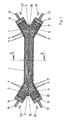
- Figure 1 shows a schematic representation of a longitudinal section by a membrane module according to the invention, the housing of which Has housing middle part 1 with a rectangular cross section, the is open at its top and in at its ends as well open Y-shaped end pieces 2, 3 each on their top two arms 4.5 and 6.7 with rectangular in this example Skip cross section.
- the hollow fiber membranes are 8.9 behind Groups placed separately in the arms of the end pieces and there embedded in the potting compounds 10.11 so that they pass through the casting compounds 10, 11 and at their ends are open.
- the ends of the hollow fiber membranes are 8 the first group in arms 4 and 6 and those of the hollow fiber membranes 9 of the second group arranged in arms 5 and 7.
- the hollow fiber membranes 8 of the first group in arms 4 and 7 and those of the second group in the arms 5 and 6 are inserted.
- the lumens of the hollow fiber membranes 8 of the first group are included the inlet device 12 and the outlet device 13, the lumens the hollow fiber membranes 9 of the second group with the inlet device 15 and the outlet device 14, wherein the inlet and outlet means by means of end caps 16 the ends of arms 4-7 are attached.
- the outside space 17 around the Hollow fiber membranes 8,9 has an inlet device 18 and one Outlet device 19, which is arranged in the bottom of the housing and are in this representation perpendicular to the plane of the drawing extend down.
- the Hollow fiber membranes 8.9 flow through the two groups in countercurrent. This is indicated by the arrows 20, 21 and 22, 23, which point in the direction of the flow.
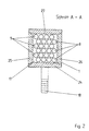
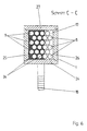
- Figure 2 shows an enlarged cross section through the middle part of the housing corresponding to the membrane module shown in Figure 1 the section A-A given there.
- the bottom 24 forms together with the side walls 25, 26 the channel-shaped middle part of the housing 1 with a rectangular cross-section.
- the middle part of the housing made of a single groove-shaped Part with a rectangular or square cross section consist.
- This representation shows in the bottom 24 with the outer space 17 around the hollow fiber membranes in Connected inlet device 18.
- the two groups of hollow fiber membranes are 8.9 in layers layered in an alternating sequence so that the Cross section of the middle part of the housing is filled.
- the single ones Layers either contain only hollow fiber membranes 8 or first group or only hollow fiber membranes 9 of the second group.
- the middle of the housing is on its top with a cover 27 closed in the form of a lid, which is shown in the Case is glued on, for example. Attaching the The lid is removed after inserting the hollow fiber membranes into the middle part of the housing and the adjoining end pieces.
- a membrane module is shown, the structure with the module shown in Figure 1 coincides with the Exception that the membrane module according to Figure 3 in the middle part of the housing 1 along the longitudinal extent of the middle housing part 1 has a separating device 28 which at this point Cross section of the middle housing part 1 around the hollow fiber membranes 8.9 completely fills the space around the hollow fiber membranes 8.9 in two substantially fluid tight from each other separate chambers 29,30 divided.
- the two chambers 29.30 each have an inlet device 18 and 31 and an outlet device 32 or 19 so that they are separated from one Fluid can be flowed through.
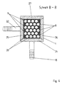
- FIG. 2 The cross section B-B through the membrane module according to FIG. 3 in the area the separating device 28 is shown enlarged in FIG.
- the middle part of the housing consisting of bottom 24 and Side parts 25, 26 are again - as shown in Figure 2, two groups of hollow fiber membranes 8,9 in alternating layers Sequence layered so that the cross section of the middle part of the housing is filled in, with the individual layers either only hollow fiber membranes 8 of the first group or only hollow fiber membranes 9 included in the second group.
- On its top is the middle part of the housing by means of the cover device 27 closed.
- the separator 28 extends outside around the hollow fiber membranes over the entire cross section of the middle part of the housing and envelops the individual hollow fiber membranes 8.9.
- Such a separator 28 can be easily layer by layer Insert the hollow fiber membranes 8.9 into the middle part of the housing 1 by first building a strip e.g. one suitable epoxy resin on the bottom 24 of the middle part of the housing 1 is coated, in which then the first hollow fiber membrane system is inserted. Then in the same place another strip of the resin is applied, which coincides with the connects the first strip and the hollow fiber membranes of the first Location so wrapped up. Each time a layer of hollow fiber membranes is inserted another resin strip will be on the same Place along the longitudinal extent of the middle housing part 1 inserted, in turn the subsequent layer of hollow fiber membranes is inserted. On the last hollow fiber membrane system a resin strip is also placed, which is used for a seal compared to the cover device 27.
- a strip e.g. one suitable epoxy resin on the bottom 24 of the middle part of the housing 1 is coated, in which then the first hollow fiber membrane system is inserted. Then in the same place another strip of the resin is applied, which coincides with the connects the first strip
- a membrane module is also shown in FIG its structure corresponds to the module shown in FIG. 1, however in the middle part of the housing 1 along the longitudinal extent of the Housing middle part 1 has a plurality of separating devices 33, 34, 35, which each have the cross section of the middle housing part 1 the hollow fiber membranes over part of the width of the middle part of the housing Fill in 1.
- separating devices 33, 34, 35 becomes a fluid flow, which flows through the inlet device 18 introduced into the outer space 17 around the hollow fiber membranes and is discharged from this via the outlet device 19 at Flow through the outer space 17 deflected several times and through the transverse flow occurring in partial areas of the outer space 17 the hollow fiber membranes the exchange of materials on the outside the hollow fiber membranes improved.
- Figure 6 shows an enlarged cross section of the membrane module according to Figure 5 at position C-C.
- the structure is in line with that Figure 2 shown identical, but the outer space 17 is around Hollow fiber membranes 8.9 over part of the width of the middle part of the housing 1 taken by the separator 34.
- the above the inlet device 18 fluid introduced into the outside space can only on the separator 34 by the at this point free space 17 flow around the hollow fiber membranes, whereby it upstream and downstream of the separator 34 there are deflections of the fluid flow.
- such a separation device can be used the entire width of the middle part of the housing, but only over one extend over part of the height or over parts the cross-sectional area of the middle part of the housing, which is arbitrary Position of the cross-section.
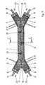
- FIG. 7 shows a membrane module according to the invention in the Top view.
- the membrane module corresponds essentially to that in Figure 1 shown, and individual parts of the membrane module below the drawing plane are outlined by dashed lines.
- the membrane module according to FIG. 7 has a removable cover device 36 in, over the middle part of the housing and parts a window 37 is inserted in the end pieces.
- the below the viewing window 37 extending hollow fiber membranes are over their longitudinal axes drawn as dash-dotted lines.
- the covering device 36 is in this case means the screws 38 so with one with the bottom of the middle part of the housing connected - not visible - screwed plate that the middle part of the housing and the end pieces on their top are closed in a fluid-tight manner by the covering device 36.
- Such a covering device 36 can be removed again at will be, for example, in the middle part of the housing and in the hollow fiber membranes located at the end pieces.
- membrane modules according to the invention or those according to the invention Processed membrane modules can be used for a variety of applications are used in which the most varied - also particle-laden - fluids are used can.
- the fluids can be gases or Trade liquids.
- the membrane modules according to the invention can preferably be use the liquid membrane technology for extraction, whereby in Outside the hollow fiber membranes themselves as a liquid membrane liquid, through which e.g. one to be extracted Component from a group's hollow fiber membranes to Hollow fiber membranes of a second group is transported.
- a interesting application for this is e.g. the separation of Enantiomers.
- Other applications generally refer to extraction technology or gas separation from both gaseous as well as from liquid media.
- Membrane modules ideally suited. Especially they can preferably be cultivated or maintained Use cell culture systems in which different material flows must be added or removed.
- a cell culture in the outer space around the hollow fiber membranes be located, and over the first group of hollow fiber membranes a supply of oxygen takes place via the a nutrient solution is fed to the second group of hollow fiber membranes and a third group of hollow fiber membranes Removal of waste products or certain ones from the cells produced substances.
- Other applications are e.g. the Preservation of whole blood or expansion / selection from stem cells or T cells for tumor therapy.
- the Use membrane modules according to the invention successfully, for example, if oxygenation combined with microfiltration or ultrafiltration is required. at some specific applications can also be found inside the Hollow fiber membranes, i.e. cells enclosed in their lumens be then over the outside space around the hollow fiber membranes be supplied. In these cases, the hollow fiber membranes in question first with the appropriate cell suspensions loaded and then closed.
- the membrane modules according to the invention can also be used advantageously for substance-specific treatments of fluids.
- Substance-specific treatments of fluids are to be understood here as treatments in which the fluid to be treated, which contains certain substances or target substances, is brought into contact with a carrier material on and / or in which functional groups or substances are immobilized, which are more specific, more selective Interact with the target substance or substances contained in the fluid, ie the substance to which the substance-specific treatment is aimed.
- Such interactions can be, for example, cation or anion exchange, hydrophilic-hydrophobic interaction, hydrogen bonding, affinity or enzymatic or catalytic reactions and the like.
- ligands are coupled or immobilized in the support material, which have the function of specifically binding an individual target substance or an entire class of substances by adsorption.
- This target substance is called a ligate.
- An example of class-specific ligands are positively charged diethylaminoethyl (DEAE) groups or negatively charged sulfonic acid (SO 3 ) groups, which adsorb the class of positively charged or negatively charged molecules.
- Specific ligands are, for example, antibodies against a specific protein which is bound to the antibody as a ligate.
- Another example of a substance-specific treatment is the extraction of active substances from cell suspensions in which genetically modified cells substances such as antibodies, hormones, growth factors or enzymes are usually produced in small concentrations to have.
- Another important application is extracorporeal Removal of unwanted substances from the human Blood plasma and the extraction of components such as Immunoglobulins or coagulation factors from donated blood plasma.
- a broad application is also catalytic or biocatalytic - enzymatic - treatment of Liquids such as the hydrolysis of oils by lipases, that are immobilized on a matrix.
- Particularly preferred substance-specific treatment methods are Process for the purification / separation of ligates from a ligate Liquid, in the membrane module according to the invention Hollow fiber membranes are contained on and / or in which Ligands for said ligates are immobilized, or in Such ligands are present outside the hollow fiber membranes. Furthermore, preferred methods are those for catalytic Treatment of liquids, wherein in the invention Membrane module hollow fiber membranes are included and / or in which catalysts are immobilized or in the exterior contain such catalysts around the hollow fiber membranes are. Catalytic processes also include biocatalytic processes Processes such as enzymatic processes. Regarding usable ligands and catalysts, with regard to the possibilities their immobilization and various substance-specific Treatments are, for example, on the explanations in EP-A-787523, the disclosure of which is referred to here is expressly referred.
- the membrane modules according to the invention can also be used use for substance-specific treatment processes in which a carrier material on and / or in which the functional Groups or substances are immobilized in the outer space around the Hollow fiber membranes located. Also for procedures where several perform various substance-specific treatments are, the modules according to the invention are outstanding use if on and / or in the hollow fiber membranes different Groups and, if necessary, various outside functional for different treatments Groups are immobilized.
Claims (40)
- Procédé de fabrication d'un module à membrane comportant une partie médiane d'enveloppe (1) qui contient au moins deux groupes de membranes à fibres creuses (8, 9) agencés en couches stratifiées et alimentés séparément, les membranes à fibres creuses à l'intérieur d'un groupe ainsi que les membranes à fibres creuses de groupes différents, au moins dans la partie médiane d'enveloppe, étant essentiellement mutuellement parallèles et chaque couche contenant seulement des membranes à fibres creuses d'un même groupe, lequel procédé comporte les étapes suivantes :a) utilisation d'une partie médiane d'enveloppe (1) en forme de gouttière, ouverte sur le dessus, qui, à ses extrémités, débouche dans des pièces d'extrémité (2, 3) également ouvertes sur le dessus, avec des bras (4, 5, 6, 7) en nombre égal au nombre de groupes de membranes à fibres creuses, la partie médiane d'enveloppe (1) et les pièces d'extrémité (2, 3) formant ensemble une coque,b) mise en place les uns sur les autres des groupes de membranes à fibres creuses, au nombre d'au moins deux, sous la forme de couches stratifiées, dans la partie médiane d'enveloppe (1) et dans les pièces d'extrémité (2, 3), de manière telle que les membranes à fibres creuses (8, 9) s'étendent essentiellement dans la direction longitudinale de la partie médiane d'enveloppe (1) et essentiellement parallèlement les unes aux autres et se terminent dans les bras (4, 5, 6, 7) des pièces d'extrémité (2, 3), les extrémités de groupes de membranes à fibres creuses (8, 9) différents étant disposées chaque fois dans des bras (4, 5, 6, 7) différents des pièces d'extrémité (2, 3) concernées,c) fermeture de la partie médiane d'enveloppe (1) et des pièces d'extrémité (2, 3) à l'aide d'un dispositif de fermeture (27, 36),d) scellage des extrémités des membranes à fibres creuses (8, 9), au moins dans les bras (4, 5, 6, 7) des pièces d'extrémité (2, 3), à l'aide d'une masse moulable (10, 11) de manière telle, que les membranes à fibres creuses (8, 9), à l'une de leurs extrémités au moins, traversent ladite masse moulable (10, 11) et soient ouvertes à cette extrémité, et qu'une chambre extérieure (17) soit formée autour des membranes à fibres creuses (8, 9), entre les membranes à fibres creuses (8, 9), la paroi intérieure de la partie médiane d'enveloppe (1), la face intérieure du dispositif de fermeture (27, 36) tournée vers la partie médiane d'enveloppe (1) et les masses moulables (10, 11).
- Procédé selon la revendication 1, caractérisé en ce que le dispositif de fermeture (27, 36) est également conformé en coque, dans laquelle sont également disposés les au moins deux groupes de membranes à fibres creuses (8, 9).
- Procédé selon une ou plusieurs des revendications 1 ou 2, caractérisé en ce qu'on utilise une partie médiane d'enveloppe (1) qui présente une section transversale intérieure rectangulaire ou carrée.
- Procédé selon une ou plusieurs des revendications 1 ou 2, caractérisé en ce qu'on utilise une partie médiane d'enveloppe (1) qui présente une section transversale intérieure semi-circulaire.
- Procédé selon une ou plusieurs des revendications 1 à 4, caractérisé en ce qu'au moins un groupe de membranes à fibres creuses (8, 9) est formé de deux sous-groupes de membranes à fibres creuses, seules des membranes à fibres creuses d'un même sous-groupe étant disposées chaque fois dans une couche.
- Procédé selon la revendication 5, caractérisé en ce que les membranes à fibres creuses (8, 9) desdits groupes, au nombre d'au moins un, sont scellées de manière telle qu'elles soient ouvertes à une extrémité seulement, et en ce que les pièces d'extrémité (2, 3) dans lesquelles les extrémités ouvertes de membranes à fibres creuses de sous-groupes différents sont scellées sont situées en des opposées de la partie médiane d'enveloppe (1).
- Procédé selon une ou plusieurs des revendications 1 à 5, caractérisé en ce que les membranes à fibres creuses des groupes sont scellées de telle sorte que leurs deux extrémités traversent la masse moulable (10, 11) et que lesdites membranes soient ouvertes à leurs deux extrémités.
- Procédé selon une ou plusieurs des revendications 1 à 5, caractérisé en ce que les membranes à fibres creuses sont scellées de telle sorte que les membranes à fibres creuses d'au moins un groupe soient fermées à l'une de leurs extrémités et ouvertes leur autre extrémité.
- Procédé selon une ou plusieurs des revendications 1 à 8, caractérisé en ce qu'on réalise un module à membrane qui contient deux groupes de membranes à fibres creuses (8, 9) disposés en couches stratifiées, pouvant être alimentés séparément.
- Procédé selon une ou plusieurs des revendications 1 à 9, caractérisé en ce que les membranes à fibres creuses (8, 9) des différents groupes, avant leur mise en place dans la partie médiane d'enveloppe (1), sont liées en nappe de fibres creuses.
- Procédé selon la revendication 10, caractérisé en ce que les membranes à fibres creuses (8, 9) sont liées à la nappe de fibres creuses concernée au moyen de fils textiles.
- Procédé selon la revendication 10 ou 11, caractérisé en ce que les nappes de fibres creuses sont liées dans des nappes tissées.
- Procédé selon la revendication 10 ou 11, caractérisé en ce que les nappes de fibres creuses sont liées dans des nappes tricotées.
- Procédé selon une ou plusieurs des revendications 10 à 13, caractérisé en ce que les nappes de fibres creuses sont empilées les unes sur les autres sous forme de couches.
- Procédé selon une ou plusieurs des revendications 10 à 14, caractérisé en ce que les groupes de membranes à fibres creuses (8, 9) sont disposés dans la partie médiane d'enveloppe (1) de manière à former une suite alternée de couches des différents groupes de membranes à fibres creuses (8, 9)
- Procédé selon une ou plusieurs des revendications 10 à 13, caractérisé en ce qu'on place l'un sur l'autre, au moins un agencement de nappes de fibres creuses empilées de chaque groupe de membranes à fibres creuses (8, 9), on les plie en accordéon parallèlement aux membranes à fibres creuses pour former une pile et on place la pile ainsi formée dans la partie médiane d'enveloppe (1), puis on place les membranes à fibres creuses (8, 9) appartenant à des groupes différents dans des bras (4, 5, 6, 7) différents des pièces d'extrémité (2, 3) concernées, les nappes de fibres creuses ayant été préalablement séparées par groupes au niveau de leurs extrémités.
- Procédé selon une ou plusieurs des revendications 1 à 16, caractérisé en ce qu'on écarte les membranes à fibres creuses (8, 9) de couches voisines à l'aide d'entretoises.
- Procédé selon une ou plusieurs des revendications 1 à 17, caractérisé en ce que dans la chambre extérieure autour des membranes à fibres creuses (8, 9), sur la longueur de la partie médiane d'enveloppe (1), on place des dispositifs de séparation (28, 33, 34, 35) qui s'étendent essentiellement transversalement à la direction longitudinale de ladite partie médiane d'enveloppe (1).
- Procédé pour le remplacement des membranes à fibres creuses (8, 9) dans un module à membranes comportant au moins deux groupes de membranes à fibres creuses (8, 9) disposés en couches stratifiées, qui peuvent être alimentés séparément, dans lequel les membranes à fibres creuses à l'intérieur d'un groupe ainsi que les membranes à fibres creuses de groupes différents sont essentiellement mutuellement parallèles, chaque couche comportant seulement des membranes à fibres creuses d'un même groupe,a) lors de la fabrication du module, on choisit une enveloppe avec un dispositif de fermeture (36) amovible,b) avant de procéder au remplacement, on retire le dispositif de fermeture (36),c) on retire de l'enveloppe les membranes à fibres creuses (8, 9) avec les masses de scellement (10, 11) aux extrémités desdites membranes à fibres creuses (8, 9) et,d) on applique un procédé selon la revendication 1,
- Module à membrane comportant une enveloppe avec une partie médiane d'enveloppe (1) allongée, qui, au niveau de ses extrémités débouche dans des pièces d'extrémité (2, 3) pourvues chacune d'au moins deux bras (4, 5, 6, 7), dans lequel au moins deux groupes de membranes à fibres creuses (8, 9) alimentés séparément sont disposés en couches stratifiées dans l'enveloppe de telle sorte, que chaque couche contienne seulement des membranes à fibres creuses d'un même groupe, que les membranes à fibres creuses (8, 9) soient disposées essentiellement dans la direction longitudinale de la partie médiane d'enveloppe (1) en étant essentiellement mutuellement parallèles et que les extrémités des membranes à fibres creuses (8, 9) se terminent dans les bras (4, 5, 6, 7) des pièces d'extrémité (2, 3), dans lequel les extrémités des groupes de membranes à fibres creuses (8, 9) sont disposées dans des bras (4, 5, 6, 7) différents des pièces d'extrémité (2, 3) et les membranes à fibres creuses (8, 9), au moins dans les bras (4, 5, 6, 7) des pièces d'extrémité (2, 3) sont scellées au moyen d'une masse moulable (10 ,11) de telle sorte qu'elles traversent la masse moulable au niveau de l'une de leurs extrémités et soient ouvertes à cette extrémité, dans lequel les extrémités ouvertes des membranes à fibres creuses (8, 9) séparées en groupes communiquent avec selon le cas un dispositif d'entrée (12, 15) ou avec un dispositif de sortie (13, 14), et dans lequel une chambre extérieure (17) est formée autour des membranes à fibres creuses (8, 9) entre les membranes à fibres creuses (8, 9), la paroi intérieure de la partie médiane d'enveloppe (1), la face intérieure du dispositif de fermeture (27, 36) tournée vers la partie médiane d'enveloppe (1) et les masses moulables (10 ,11), caractérisé en ce que la partie médiane d'enveloppe (1) et les pièces d'extrémité (2, 3) avec leurs bras (4, 5, 6, 7) sont conformées en gouttières ouvertes sur le dessus et forment ensemble une coque d'enveloppe, et en ce que la partie médiane d'enveloppe (1) et les pièces d'extrémité (2, 3) dans leur partie supérieure sont fermées de manière étanche au fluide par un dispositif de fermeture (27, 36).
- Module à membrane selon la revendication 20, caractérisé en ce que le dispositif de fermeture (27, 36) est également conformé en coque d'enveloppe et que des couches stratifiées des groupes de membranes à fibres creuses (8, 9) sont également disposées dans celle-ci.
- Module à membrane selon une ou plusieurs des revendications 20 ou 21, caractérisé en ce que la partie médiane d'enveloppe (1) a une section transversale intérieure rectangulaire ou carrée.
- Module à membrane selon une ou plusieurs des revendications 20 ou 21, caractérisé en ce que la partie médiane d'enveloppe (1) a une section transversale intérieure semi-circulaire.
- Module à membrane selon une ou plusieurs des revendications 20 à 23, caractérisé en ce que le dispositif de fermeture (27, 36) est amovible.
- Module à membrane selon une ou plusieurs des revendications 20 à 24, caractérisé en ce qu'au moins un groupe de membranes à fibres creuses (8, 9) est formé d'au moins deux sous-groupes de membranes à fibres creuses disposés en couches stratifiées.
- Module à membrane selon la revendication 25, caractérisé en ce que chaque couche contient seulement des membranes à fibres creuses d'un même sous-groupe et que les membranes à fibres creuses dudit groupe, au nombre d'au moins un, sont scellées de manière telle qu'elles soient ouvertes seulement à une extrémité, et que les pièces d'extrémité dans lesquelles les extrémités de membranes à fibres creuses appartenant à des sous-groupes différents sont scellées, sont disposées en des extrémités opposées de la partie médiane d'enveloppe (1).
- Module à membrane selon une ou plusieurs des revendications 20 à 25, caractérisé en ce que les membranes à fibres creuses sont scellées de manière telle que leurs deux extrémités traversent la masse moulable (10, 11) et sont ouvertes, les membranes à fibres creuses (8, 9) séparées en groupes communiquant par leur extrémité ouverte les unes avec un dispositif d'entrée (12, 15) et les autres avec un dispositif de sortie (13, 14).
- Module à membrane selon une ou plusieurs des revendications 20 à 25, caractérisé en ce que les membranes à fibres creuses d'au moins un groupe sont ouvertes à une extrémité et fermées à l'autre extrémité.
- Module à membrane selon une ou plusieurs des revendications 20 à 28, caractérisé en ce que deux groupes de membranes à fibres creuses (8, 9) sont disposés dans le module de membrane.
- Module à membrane selon une ou plusieurs des revendications 20 à 29, caractérisé en ce qu'il présente dans la chambre extérieure (17) autour des membranes à fibres creuses (8, 9), sur la longueur de la partie médiane d'enveloppe (1), au moins un dispositif de séparation (28, 33, 34, 35) qui s'étend essentiellement transversalement à ladite longueur.
- Module à membrane selon la revendication 30, caractérisé en ce que le dispositif de séparation (28), au nombre d'au moins un, divise la chambre extérieure en chambres (29, 30) séparées de manière essentiellement étanche au fluide.
- Module à membrane selon la revendication 31, caractérisé en ce qu'au moins une des chambres (29, 30) comporte au moins un dispositif d'entrée (18, 31).
- Module à membrane selon la revendication 30, caractérisé en ce que le dispositif de séparation (33, 34, 35) au nombre d'au moins un, s'étend sur une partie de la surface en section transversale de la partie médiane d'enveloppe (1).
- Module à membrane selon une ou plusieurs des revendications 20 à 33, caractérisé en ce qu'il contient une succession de couches des différents groupes de membranes à fibres creuses (8, 9) disposées en alternance.
- Module à membrane selon une ou plusieurs des revendications 20 à 34, caractérisé en ce que les membranes à fibres creuses (8, 9) des différents groupes sont liées en nappes de fibres creuses.
- Module à membrane selon la revendication 35, caractérisé en ce que les membranes à fibres creuses (8, 9) sont liées à la nappe de fibres creuses concernée au moyen de fils textiles.
- Module à membrane selon une ou plusieurs des revendications 35 ou 36, caractérisé en ce que des nappes de fibres creuses sont empilées en couches.
- Utilisation du module à membrane selon une ou plusieurs des revendications 20 à 37 pour séparer des éniantomères.
- Utilisation du module à membrane selon une ou plusieurs des revendications 20 à 37 pour élever ou obtenir des systèmes de culture de cellules.
- Utilisation du module à membrane selon une ou plusieurs des revendications 20 à 37 pour le traitement sélectif de fluides.
Applications Claiming Priority (3)
| Application Number | Priority Date | Filing Date | Title |
|---|---|---|---|
| DE19704005 | 1997-02-04 | ||
| DE19704005 | 1997-02-04 | ||
| PCT/EP1998/000516 WO1998033581A1 (fr) | 1997-02-04 | 1998-01-31 | Module a fibres creuses d'au moins deux groupes, et mode de fabrication |
Publications (2)
| Publication Number | Publication Date |
|---|---|
| EP0963239A1 EP0963239A1 (fr) | 1999-12-15 |
| EP0963239B1 true EP0963239B1 (fr) | 2002-07-31 |
Family
ID=7819173
Family Applications (1)
| Application Number | Title | Priority Date | Filing Date |
|---|---|---|---|
| EP98908029A Expired - Lifetime EP0963239B1 (fr) | 1997-02-04 | 1998-01-31 | Module a fibres creuses d'au moins deux groupes, et mode de fabrication |
Country Status (4)
| Country | Link |
|---|---|
| US (1) | US6271023B1 (fr) |
| EP (1) | EP0963239B1 (fr) |
| DE (1) | DE59804998D1 (fr) |
| WO (1) | WO1998033581A1 (fr) |
Families Citing this family (19)
| Publication number | Priority date | Publication date | Assignee | Title |
|---|---|---|---|---|
| EP1159444B1 (fr) * | 1999-03-09 | 2004-05-26 | Acordis Industrial Fibers GmbH | Module a membranes destine a tester des principes actifs sur des cellules |
| US6485650B1 (en) | 2000-08-28 | 2002-11-26 | Facilichem, Inc. | Liquid membrane separation of enantiomers |
| JP2003000631A (ja) * | 2001-06-25 | 2003-01-07 | Metoran:Kk | 体温調節具およびこれを用いた体温調節装置 |
| US20070004023A1 (en) * | 2003-05-19 | 2007-01-04 | Michael Trachtenberg | Methods, apparatuses, and reactors for gas separation |
| US10526299B2 (en) * | 2004-12-22 | 2020-01-07 | Chemtor, Lp | Fiber conduit reactor with a heat exchange medium inlet and a heat exchange medium outlet |
| US7803274B2 (en) * | 2008-04-30 | 2010-09-28 | Celgard Llc | Contained liquid membrane contactor and a method of manufacturing the same |
| US20100051549A1 (en) * | 2008-08-29 | 2010-03-04 | Milton Roy Company | Heat recuperating membrane distillation apparatus and system |
| EP2168666A1 (fr) * | 2008-09-25 | 2010-03-31 | Gambro Lundia AB | Membrane irradiée pour expansion cellulaire |
| US9630141B2 (en) * | 2009-02-20 | 2017-04-25 | Cameron Solutions, Inc. | Membrane filter element with multiple fiber types |
| DE102009037015A1 (de) * | 2009-08-07 | 2011-02-17 | Michael Hajek | Vorrichtung und Verfahren zur Eliminierung von bioschädlichen Stoffen aus Körperflüssigkeiten |
| KR20120091161A (ko) | 2009-09-30 | 2012-08-17 | 멤브라나 게엠베하 | 유체 불투과성 세그먼트를 갖는 중공 섬유 멤브레인 매트 및 관련 방법 |
| EP2363196B1 (fr) | 2010-03-03 | 2017-07-12 | Gambro Lundia AB | Dispositif de diffusion et/ou filtration |
| BR112014005221A2 (pt) | 2011-09-08 | 2017-03-28 | Safe Bt Inc | uso de materiais de fibra oca modificada para a remoção de exotoxinas produzidas por escherichia coli a partir de liquidos, de preferência a partir de sangue e de plasma, bem como seu uso para o tratamento de doenças concomitantes |
| NL2009330C2 (en) | 2012-08-16 | 2014-02-18 | X Flow Bv | Filter module and filter apparatus containing such filter module. |
| US10507430B2 (en) | 2014-04-03 | 2019-12-17 | Mitsubishi Chemical Corporation | Hollow fiber membrane sheet-like object, method of manufacturing hollow fiber membrane sheet-like object, hollow fiber membrane sheet laminate, method of manufacturing hollow fiber membrane sheet laminate, hollow fiber membrane module and method of manufacturing hollow fiber membrane module |
| US11287403B2 (en) * | 2016-01-07 | 2022-03-29 | Board Of Regents, The University Of Texas System | Ion chromatography system and methods utilizing a weak acid or weak base extraction device |
| BR112020004994A2 (pt) * | 2017-09-17 | 2020-09-15 | Steven Paul Keller | sistemas, dispositivos e métodos para remoção extracorpórea de dióxido de carbono |
| US20210371852A1 (en) * | 2018-05-18 | 2021-12-02 | Children's National Medical Center | System of cell expansion and methods of using the same |
| JP7305758B2 (ja) * | 2018-09-29 | 2023-07-10 | フレセニウス・メディカル・ケア・ドイチュラント・ゲーエムベーハー | 界面媒体と共に使用するための透析デバイス、透析システム、透析デバイスの使用、透析システムを確立するための方法、透析システムを充填および/またはプライミングするための方法、ならびに透析システムから空気を除去するための方法 |
Family Cites Families (20)
| Publication number | Priority date | Publication date | Assignee | Title |
|---|---|---|---|---|
| US3612282A (en) * | 1969-08-14 | 1971-10-12 | Sing Wang Cheng | Supporting structures and containing vessels for reverse osmosis and filtration |
| US4231878A (en) * | 1975-07-16 | 1980-11-04 | Esmond William G | Capillary mass transfer device |
| DE2652856C2 (de) * | 1976-11-20 | 1983-12-22 | Fresenius AG, 6380 Bad Homburg | Stoffaustauscher für medizinische Zwecke |
| US4211597A (en) * | 1977-06-10 | 1980-07-08 | Cordis Dow Corp. | Method for making artificial kidney |
| US4184922A (en) * | 1977-11-11 | 1980-01-22 | The Government Of The United States | Dual circuit, woven artificial capillary bundle for cell culture |
| DE2806237C2 (de) * | 1978-02-14 | 1983-03-24 | Sartorius GmbH, 3400 Göttingen | Vorrichtung zum Entfernen der harnpflichtigen Stoffe aus dem menschlichen Blut |
| US5002871A (en) * | 1986-08-18 | 1991-03-26 | The Coca-Cola Company | Enzymatic membrane method for the synthesis and separation of peptides |
| US5043260A (en) | 1987-11-02 | 1991-08-27 | Rhode Island Hospital | Perfusion device with hepatocytes |
| JPH0696098B2 (ja) * | 1988-05-27 | 1994-11-30 | 株式会社クラレ | 中空糸型流体処理装置 |
| US5416022A (en) | 1988-08-10 | 1995-05-16 | Cellex Biosciences, Inc. | Cell culture apparatus |
| DE4005132A1 (de) | 1990-02-17 | 1991-08-22 | Akzo Gmbh | Verfahren zum herstellen von hohlfadenstapeln |
| CA2065918A1 (fr) | 1991-04-22 | 1992-10-23 | Bradley W. Reed | Modules de membranes liquides a epaisseur utile minimale et methodes de fabrication connexes |
| US5169529A (en) | 1991-04-22 | 1992-12-08 | Hoechst Celanese Corporation | Liquid membrane modules with minimal effective membrane thickness and methods of making the same |
| US5449457A (en) * | 1991-04-22 | 1995-09-12 | Hoechst Celanese Corporation | Liquid membrane modules with minimal effective membrane thickness and methods of making the same |
| EP0531631B1 (fr) * | 1991-06-19 | 1996-10-09 | Endotronics, Inc. | Appareil pour la culture de cellules |
| US5282966A (en) * | 1992-10-08 | 1994-02-01 | E. I. Du Pont De Nemours And Company | Package for permeation separation device |
| US5712154A (en) * | 1995-06-07 | 1998-01-27 | W.R. Grace & Co.-Conn. | Dual fiber bioreactor |
| ATE235952T1 (de) | 1996-02-01 | 2003-04-15 | Mat Adsorption Technologies Gm | Vorrichtung und verfahren zur stoffspezifischen behandlung von fluiden |
| US6086769A (en) * | 1996-09-16 | 2000-07-11 | Commodore Separation Technologies, Inc. | Supported liquid membrane separation |
| US5955353A (en) * | 1997-05-22 | 1999-09-21 | Excorp Medical, Inc. | Hollow fiber bioreactor with an extrafilament flow plug |
-
1998
- 1998-01-31 US US09/355,745 patent/US6271023B1/en not_active Expired - Lifetime
- 1998-01-31 DE DE59804998T patent/DE59804998D1/de not_active Expired - Lifetime
- 1998-01-31 WO PCT/EP1998/000516 patent/WO1998033581A1/fr active IP Right Grant
- 1998-01-31 EP EP98908029A patent/EP0963239B1/fr not_active Expired - Lifetime
Also Published As
| Publication number | Publication date |
|---|---|
| WO1998033581A1 (fr) | 1998-08-06 |
| EP0963239A1 (fr) | 1999-12-15 |
| US6271023B1 (en) | 2001-08-07 |
| DE59804998D1 (de) | 2002-09-05 |
Similar Documents
| Publication | Publication Date | Title |
|---|---|---|
| EP0963239B1 (fr) | Module a fibres creuses d'au moins deux groupes, et mode de fabrication | |
| EP0956147B1 (fr) | Module a membranes constituees de fibres creuses et disposees en couches | |
| EP1289630B1 (fr) | Module a elements de membrane pour ecoulement partiel et ecoulement total | |
| EP0989904B1 (fr) | Module membranaire a membranes en fibres creuses enrobees d'un cote | |
| WO1998033581A9 (fr) | Module a fibres creuses d'au moins deux groupes, et mode de fabrication | |
| EP2996796B1 (fr) | Oxygénateur et son utilisation | |
| DE10393754B4 (de) | Hohlfaserkassette und modular aufgebautes Kassettensystem | |
| DE10106722B4 (de) | Spezielles Hohlfaser-Membranmodul für den Einsatz in stark durch fouling beeinträchtigten Prozessen und seine Herstellung | |
| EP2396052B1 (fr) | Dispositif de traitement d'un liquide biologique | |
| EP0787523B1 (fr) | Appareil et procédé pour le traitement spécifique à la matière des fluides | |
| DE2238708B2 (de) | Diffusionszelle | |
| EP0264696A2 (fr) | Appareil échangeur de masse | |
| DE4342485C1 (de) | Vorrichtung zur Entfernung von gasförmigen Stoffen aus einem Gasstrom | |
| DE19943921C1 (de) | Partikelgängige Vorrichtung zur Durchführung von Stofftrennungen mittels poröser flächiger Adsorptionsmembranen | |
| EP0951343B1 (fr) | Module membranaire pour traitement fluidique specifique | |
| DE69815688T2 (de) | Verfahren zur hohlfasern filtration | |
| DE3241315T1 (de) | Verfahren und Vorrichtung zum hochwirksamen Ultrafiltrieren komplexer fließfähiger Medien | |
| DE4308850A1 (de) | Hohlfadenmatte | |
| DE4427354C2 (de) | Membranmodul zur Entfernung von gasförmigen Stoffen aus einem Gasstrom (Flüssigkeitsstrom) | |
| DE3519620A1 (de) | Einrichtung und verfahren zur steuerung der diffusion von fluidkomponenten | |
| DE102018006286B3 (de) | Bioreaktor mit Filtereinheit und Verfahren zur Behandlung einer Zellbrühe | |
| WO2011023605A1 (fr) | Module de fibres creuses tressées tridimensionnelles pour échanges de matière et d'énergie | |
| DE3733542A1 (de) | Vorrichtung zum stoffaustausch | |
| EP0930932A1 (fr) | Module de plaque tubulaire | |
| EP0968037B1 (fr) | Dispositif pour le traitement de liquides |
Legal Events
| Date | Code | Title | Description |
|---|---|---|---|
| PUAI | Public reference made under article 153(3) epc to a published international application that has entered the european phase |
Free format text: ORIGINAL CODE: 0009012 |
|
| 17P | Request for examination filed |
Effective date: 19990724 |
|
| AK | Designated contracting states |
Kind code of ref document: A1 Designated state(s): DE ES FR GB IT |
|
| RAP1 | Party data changed (applicant data changed or rights of an application transferred) |
Owner name: MEMBRANA GMBH |
|
| RIC1 | Information provided on ipc code assigned before grant |
Free format text: 7B 01D 63/04 A, 7B 01D 63/02 B, 7B 01D 61/28 B, 7B 01D 61/38 B, 7B 01D 53/22 B, 7B 01D 65/00 B, 7A 61M 1/14 B, 7G 01N 33/543 B |
|
| GRAG | Despatch of communication of intention to grant |
Free format text: ORIGINAL CODE: EPIDOS AGRA |
|
| 17Q | First examination report despatched |
Effective date: 20011031 |
|
| RAP1 | Party data changed (applicant data changed or rights of an application transferred) |
Owner name: MAT ADSORPTION TECHNOLOGIES GMBH & CO. KG |
|
| GRAG | Despatch of communication of intention to grant |
Free format text: ORIGINAL CODE: EPIDOS AGRA |
|
| GRAH | Despatch of communication of intention to grant a patent |
Free format text: ORIGINAL CODE: EPIDOS IGRA |
|
| GRAH | Despatch of communication of intention to grant a patent |
Free format text: ORIGINAL CODE: EPIDOS IGRA |
|
| RAP1 | Party data changed (applicant data changed or rights of an application transferred) |
Owner name: MAT ADSORPTION TECHNOLOGIES GMBH & CO. KG |
|
| GRAA | (expected) grant |
Free format text: ORIGINAL CODE: 0009210 |
|
| AK | Designated contracting states |
Kind code of ref document: B1 Designated state(s): DE ES FR GB IT |
|
| REG | Reference to a national code |
Ref country code: GB Ref legal event code: FG4D Free format text: NOT ENGLISH |
|
| REF | Corresponds to: |
Ref document number: 59804998 Country of ref document: DE Date of ref document: 20020905 |
|
| GBT | Gb: translation of ep patent filed (gb section 77(6)(a)/1977) |
Effective date: 20020827 |
|
| PG25 | Lapsed in a contracting state [announced via postgrant information from national office to epo] |
Ref country code: ES Free format text: LAPSE BECAUSE OF FAILURE TO SUBMIT A TRANSLATION OF THE DESCRIPTION OR TO PAY THE FEE WITHIN THE PRESCRIBED TIME-LIMIT Effective date: 20030130 |
|
| ET | Fr: translation filed | ||
| PLBE | No opposition filed within time limit |
Free format text: ORIGINAL CODE: 0009261 |
|
| STAA | Information on the status of an ep patent application or granted ep patent |
Free format text: STATUS: NO OPPOSITION FILED WITHIN TIME LIMIT |
|
| 26N | No opposition filed |
Effective date: 20030506 |
|
| PGFP | Annual fee paid to national office [announced via postgrant information from national office to epo] |
Ref country code: DE Payment date: 20140203 Year of fee payment: 17 |
|
| PGFP | Annual fee paid to national office [announced via postgrant information from national office to epo] |
Ref country code: FR Payment date: 20140121 Year of fee payment: 17 Ref country code: IT Payment date: 20140124 Year of fee payment: 17 |
|
| PGFP | Annual fee paid to national office [announced via postgrant information from national office to epo] |
Ref country code: GB Payment date: 20140123 Year of fee payment: 17 |
|
| REG | Reference to a national code |
Ref country code: DE Ref legal event code: R119 Ref document number: 59804998 Country of ref document: DE |
|
| GBPC | Gb: european patent ceased through non-payment of renewal fee |
Effective date: 20150131 |
|
| PG25 | Lapsed in a contracting state [announced via postgrant information from national office to epo] |
Ref country code: GB Free format text: LAPSE BECAUSE OF NON-PAYMENT OF DUE FEES Effective date: 20150131 Ref country code: DE Free format text: LAPSE BECAUSE OF NON-PAYMENT OF DUE FEES Effective date: 20150801 |
|
| REG | Reference to a national code |
Ref country code: FR Ref legal event code: ST Effective date: 20150930 |
|
| PG25 | Lapsed in a contracting state [announced via postgrant information from national office to epo] |
Ref country code: FR Free format text: LAPSE BECAUSE OF NON-PAYMENT OF DUE FEES Effective date: 20150202 |
|
| PG25 | Lapsed in a contracting state [announced via postgrant information from national office to epo] |
Ref country code: IT Free format text: LAPSE BECAUSE OF NON-PAYMENT OF DUE FEES Effective date: 20150131 |