EP0989588B1 - Lampe und entsprechende Bildlesevorrichtung - Google Patents
Lampe und entsprechende Bildlesevorrichtung Download PDFInfo
- Publication number
- EP0989588B1 EP0989588B1 EP99204253A EP99204253A EP0989588B1 EP 0989588 B1 EP0989588 B1 EP 0989588B1 EP 99204253 A EP99204253 A EP 99204253A EP 99204253 A EP99204253 A EP 99204253A EP 0989588 B1 EP0989588 B1 EP 0989588B1
- Authority
- EP
- European Patent Office
- Prior art keywords
- lamp
- heat
- light
- accumulating
- lamp unit
- Prior art date
- Legal status (The legal status is an assumption and is not a legal conclusion. Google has not performed a legal analysis and makes no representation as to the accuracy of the status listed.)
- Expired - Lifetime
Links
Images


Classifications
-
- H—ELECTRICITY
- H04—ELECTRIC COMMUNICATION TECHNIQUE
- H04N—PICTORIAL COMMUNICATION, e.g. TELEVISION
- H04N1/00—Scanning, transmission or reproduction of documents or the like, e.g. facsimile transmission; Details thereof
- H04N1/024—Details of scanning heads ; Means for illuminating the original
- H04N1/028—Details of scanning heads ; Means for illuminating the original for picture information pick-up
- H04N1/02815—Means for illuminating the original, not specific to a particular type of pick-up head
- H04N1/02845—Means for illuminating the original, not specific to a particular type of pick-up head using an elongated light source, e.g. tubular lamp, LED array
- H04N1/0287—Means for illuminating the original, not specific to a particular type of pick-up head using an elongated light source, e.g. tubular lamp, LED array using a tubular lamp or a combination of such lamps
-
- H—ELECTRICITY
- H01—ELECTRIC ELEMENTS
- H01J—ELECTRIC DISCHARGE TUBES OR DISCHARGE LAMPS
- H01J61/00—Gas-discharge or vapour-discharge lamps
- H01J61/02—Details
- H01J61/52—Cooling arrangements; Heating arrangements; Means for circulating gas or vapour within the discharge space
-
- H—ELECTRICITY
- H01—ELECTRIC ELEMENTS
- H01J—ELECTRIC DISCHARGE TUBES OR DISCHARGE LAMPS
- H01J61/00—Gas-discharge or vapour-discharge lamps
- H01J61/70—Lamps with low-pressure unconstricted discharge having a cold pressure < 400 Torr
-
- H—ELECTRICITY
- H01—ELECTRIC ELEMENTS
- H01J—ELECTRIC DISCHARGE TUBES OR DISCHARGE LAMPS
- H01J65/00—Lamps without any electrode inside the vessel; Lamps with at least one main electrode outside the vessel
- H01J65/04—Lamps in which a gas filling is excited to luminesce by an external electromagnetic field or by external corpuscular radiation, e.g. for indicating plasma display panels
- H01J65/042—Lamps in which a gas filling is excited to luminesce by an external electromagnetic field or by external corpuscular radiation, e.g. for indicating plasma display panels by an external electromagnetic field
- H01J65/046—Lamps in which a gas filling is excited to luminesce by an external electromagnetic field or by external corpuscular radiation, e.g. for indicating plasma display panels by an external electromagnetic field the field being produced by using capacitive means around the vessel
-
- H—ELECTRICITY
- H04—ELECTRIC COMMUNICATION TECHNIQUE
- H04N—PICTORIAL COMMUNICATION, e.g. TELEVISION
- H04N1/00—Scanning, transmission or reproduction of documents or the like, e.g. facsimile transmission; Details thereof
- H04N1/024—Details of scanning heads ; Means for illuminating the original
- H04N1/028—Details of scanning heads ; Means for illuminating the original for picture information pick-up
- H04N1/02815—Means for illuminating the original, not specific to a particular type of pick-up head
- H04N1/02885—Means for compensating spatially uneven illumination, e.g. an aperture arrangement
Definitions
- the present invention relates to a lamp unit suitable for use in an image reading apparatus which is called an image scanner or the like, as well as an image reading apparatus using the lamp unit.
- a cylindrically shaped lamp is disposed in a widthwise direction of an original, and light produced from the lamp is applied to the original. Then, the light reflected by the original or the light transmitted through the original is read by an image sensor, such as a CCD image sensor.
- a hot-cathode tube of a so-called both-end electrode type is known in which, as shown in Fig. 16, a pair of electrodes 52a and 52b serving as hot cathodes are disposed at both ends of a gas-filled tube 51 in which a gas is filled.
- Reference numeral 53 denotes a fluorescent material applied to an inner peripheral surface of the gas-filled tube 51.
- the hot cathode refers to an electrode which generates heat upon being energized, and emits thermions.
- a cold-cathode tube of a so-called both-end electrode type is also known in which, as shown in Fig. 17, a pair of electrodes 54a and 54b serving as cold cathodes are disposed at both ends of a gas-filled tube 51.
- the cold cathode refers to an electrode which emits electrons when a strong electric field is applied thereto.
- a cathode tube of a so-called outer-surface electrode type is also known in which, as shown in Fig. 18, a pair of elongated electrodes 55a and 55b are disposed substantially over entire longitudinal regions of the outer peripheral surface of a gas-filled tube 51 in such a manner as to face each other.
- the electrodes 55a and 55b are generally configured as cold cathodes, but in a case where the electrodes 55a and 55b can be configured as hot cathodes, such an arrangement may be adopted.
- a rare gas such as neon (Ne) gas or xenon (Xe) gas, or mercury (Hg) gas is filled in the gas-filled tube 51, depending on applications.
- a rare gas such as neon (Ne) gas or xenon (Xe) gas, or mercury (Hg) gas is filled in the gas-filled tube 51, depending on applications.
- the overall quantity of light from the lamp 56 declines as shown by reference character B1, and the quantity of light declines more in a central portion in the longitudinal direction than in opposite end portions.
- a change ⁇ 1 in the quantity of light in the X-direction when 100% of the quantity of light immediately after lighting-up is set as a reference will be referred to as a rate of change in the quantity of light.
- the difference ⁇ 2 between a maximum rate of change in the quantity of light (normally in a central portion) and a minimum rate of change in the quantity of light (normally in opposite end portions) in that line of distribution of the quantity of light will be referred to as a difference in the rate of change in the quantity of light.
- the quantity of emission of light is the largest in the case of the cathode tube of the outer-surface electrode type (Fig. 18), the next largest is the hot-cathode tube of the both-end electrode type (Fig. 16), and the smallest is the cold-cathode tube of the both-end electrode type (Fig. 17). That is, with respect to the quantity of emission of light, it can be said that
- the cathode tube of the outer-surface electrode type (Fig. 18) has a quantity of emission of light which is about three times greater than that of the cold-cathode tube of the both-end electrode type (Fig. 17).
- both the rate of change ⁇ 1 in the quantity of light and the difference ⁇ 2 in the rate of change in the quantity of light are relatively small in the case of the hot-cathode tube of the both-end electrode type (Fig. 16) and the cold-cathode tube of the both-end electrode type (Fig. 17).
- both the rate of change ⁇ 1 in the quantity of light and the difference ⁇ 2 in the rate of change in the quantity of light are considerably large in the case of the cathode tube of the outer-surface electrode type (Fig. 18).
- the cathode tube of the outer-surface electrode type (Fig. 18) has a large quantity of emission of light, and is therefore suitable for reading clear images.
- this lamp has a considerably large rate of change ⁇ 1 in the quantity of light and a considerably large difference ⁇ 2 in the rate of change in the quantity of light, if this lamp is used as the lamp for the image reading apparatus, the characteristics of read images deteriorate due to the change over time in the quantity of light. Specifically, there arises the problem that the quantity of light changes substantially between the start of reading of the original and the end of reading, the reproduced image becomes gradually dark, and a central portion, in particular, becomes dark.
- Japanese Patent Application Laid-Open No. 123214/1995 discloses an image input apparatus in which, as shown in Figs. 19 and 20, heat is insulated by maintaining heat which is generated by a fluorescent lamp 92 itself during the emission of light by attaching a heat insulating material 93 to the fluorescent lamp 92 in close contact therewith so as to improve the lighting-up rise characteristic, and the fluorescent lamp 92 is controlled to an appropriate quantity of light by detecting the illuminance by a photosensor 98.
- reference numeral 91 denotes an original-reading background plate; 94, a mirror; 95, a slit; 96, a lens; 97, a CCD image sensor; and 99, an original which is fed in the direction of arrow.
- the conventional technique disclosed in this publication is aimed at improving the lighting-up rise characteristic of the lamp, and gives no disclosure as to the reduction of both the rate of change ⁇ 1 in the quantity of light and the difference ⁇ 2 in the rate of change in the quantity of light to satisfactory levels.
- JP 06118517A discloses an illuminating device comprising a fluorescent lamp for use in a copying apparatus, an image reader or the like.
- the inventor of the present application found that there is a close relationship between the amount of change in the temperature of the tube wall of the lamp in a predetermined time duration and the rate of change in the quantity of light from the lamp in that time duration, and that the rate of change in the quantity of light becomes large with an increase in the tube wall temperature.
- the present invention has been devised in view of the above-described knowledge, and its viewpoint consists in reducing both the rate of change ⁇ 1 in the quantity of light and the difference ⁇ 2 in the rate of change in the quantity of light to satisfactory levels concerning lamps of various types.
- another viewpoint of the present invention lies in the provision of an image reading apparatus using this lamp.
- still another viewpoint of the present invention lies in suitably controlling the lamp used for the image reading apparatus.
- the heat-accumulating means referred to in the description that follows means a material having a property whereby the lamp can be deprived of its heat, and that heat can be accumulated inside itself.
- the heat-accumulating means refers to a material which is capable of reducing the rate of increase in the temperature of the lamp immediately after lighting-up, and of prolonging the time required for cooling the lamp by the radiation of heat, and the heat-accumulating means is preferably a material having a large heat capacity.
- the phrase “the heat-accumulating means (or the heat-accumulating member) is provided around the lamp” is meant to include cases where the heat-accumulating means is directly secured to an outer peripheral surface or an inner peripheral surface of the lamp, or cases where the heat-accumulating means is disposed in proximity to the lamp in a state in which some member or other is interposed therebetween.
- a lamp unit comprising:
- the lamp unit may comprise: a lamp including a hollow cylindrical gas-filled tube in which a gas is filled and a pair of electrodes provided at opposite end portions of the gas-filled tube; and heat-accumulating means provided around the lamp, wherein the heat-accumulating means has silicone rubber provided around the lamp and a metallic member provided in contact with an outer peripheral surface of the silicone rubber.
- the heat-accumulating means is provided around the lamp including the hollow cylindrical gas-filled tube in which a gas is filled and the pair of electrodes provided at the opposite end portions of the gas-filled tube (the lamp of the both-end electrode type such as those shown in Figs.
- the tube wall of the lamp is deprived of its heat by this heat-accumulating means, and that heat is accumulated inside the heat-accumulating means. Accordingly, the rate of increase in the temperature of the lamp after lighting-up is reduced, with the result that both the rate of change ⁇ 1 in the quantity of light and the difference ⁇ 2 in the rate of change in the quantity of light are made small. As described above, if the temperature of the tube wall of the lamp increases, the rate of change in the quantity of light becomes large. To put it differently, if the temperature of the tube wall of the lamp can be controlled, the rate of change in the quantity of light can be also controlled.
- the heat-accumulating means since the heat-accumulating means has silicone rubber provided around the lamp and a metallic member provided in contact with the outer peripheral surface of the silicone rubber, the following operation and effects can be obtained. Namely, since the silicone rubber excels in its thermal conductivity and characteristic of close contact (a property in which its surface is active and bites into various materials), whereas the metallic member excels in a heat-accumulating characteristic. Hence, the heat of the lamp is transmitted satisfactorily to the metallic member through the silicone rubber, and is accumulated in the metallic member. Moreover, since the silicone rubber itself also has a heat-accumulating characteristic, the heat of the lamp is also accumulated in the silicone rubber.
- the metallic member can also function as a protecting member for the lamp.
- the lamp unit may comprise:
- the lamp unit in accordance with the present invention has as its viewpoints of invention those described in the best mode for carrying out the invention and those which are apparent from the drawings.
- An image reading apparatus in accordance with the present invention comprises: a light source for emitting light for illuminating an original; and an image sensor for receiving a light image from the original and providing an output as an electrical signal, wherein the light source is constituted by the lamp unit according to any one of claims 1 to 11.
- the rate of change ⁇ 1 in the quantity of light from the lamp and the difference ⁇ 2 in the rate of change in the quantity of light are reduced, and an excellent image reading apparatus can be obtained.
- the lamp is turned off'after completion of the illumination for reading the original.
- the arrangement is provided such that the lamp is turned off after completion of the illumination for reading the original, it is possible to avoid the saturation of heat in the heat-accumulating means or the heat-accumulating member by suppressing an increase in the temperature of the lamp. Consequently, it is possible to reliably reduce the rate of change ⁇ 1 in the quantity of light and the difference ⁇ 2 in the rate of change in the quantity of light, and an excellent image reading apparatus can be obtained.
- the image reading apparatus in accordance with the present invention has as its viewpoints of invention those described in the best mode for carrying out the invention and those which are apparent from the drawings.
- Fig. 1 is a diagram useful for illustrating an embodiment of essential portions of an image reading apparatus in a case where a lamp unit in accordance with the present invention is used as a light source of the image reading apparatus.
- a carriage 9 is disposed at a position below original table glass 8 on which an original 7 is placed.
- This carriage 9 is driven by a conveying device 11 such as a wire or a belt, and reciprocates in parallel to the original table glass 8, shown by arrow C and arrow C'.
- the left-and-right direction in the drawing is the longitudinal direction of the original, and the direction perpendicular to the plane of the drawing is the widthwise direction of the original.
- the carriage 9 When the carriage 9 moves in the direction of arrow C (in the rightward direction in the drawing), the carriage 9 reads the original 7 in its longitudinal direction, i.e., the vertical scanning direction.
- various optical elements such as a lamp unit 6 surrounded by a light-shielding plate 12, a first mirror 13, a second mirror 14, a CCD image sensor 15 serving as an image reading sensor, and a lens 16 for focusing the optical image of the original 7 onto the CCD image sensor 15.
- the lamp unit 6 extends in the widthwise direction of the original 7, and the width of its effective light-emitting portion is set to be wider than the width of the original 7.
- the CCD image sensor 15 is an image sensor for producing an image signal by fetching outputs of a plurality of photoelectric detectors, such as photodiodes, which are arranged in a straight line as a time-series signal by using a charge coupled device (CCD).
- the photoelectric detectors are arranged in the widthwise direction of the original 7, i.e., in a perpendicular direction to the plane of the drawing of Fig. 1.
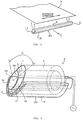
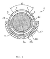
- Figs. 3 and 4 are diagrams which illustrate a first arrangement of the lamp unit, in which Fig. 3 is a fragmentary perspective view and Fig. 4 is a cross-sectional view.
- this lamp unit 6 is comprised of a hollow cylindrical gas-filled tube 1 in which, for example, xenon gas Xe is filled; a lamp 3 of an outer-surface electrode type having a pair of electrodes 2a and 2b secured to an outer peripheral surface of the gas-filled tube 1 by bonding or the like; a cladding tube 4 surrounding the lamp 3; and a heat-accumulating means 20 provided in contact with the outer peripheral surface of the cladding tube 4.
- the gas-filled tube 1 is formed from, for example, a transparent glass tube, and its internal surface is coated with a fluorescent material 1a which emits, for instance, white light.
- the electrodes 2a and 2b are formed by, for example, attaching aluminum tapes substantially over entire longitudinal regions of the outer peripheral surface of a gas-filled tube 51, as shown in Fig. 3. When the lamp 3 is made to emit light, a high voltage of, for instance, 3 kV or thereabouts, is applied across these electrodes 2a and 2b.
- the cladding tube 4 is made of a synthetic resin having an electrically insulating property, and is formed into a hollow cylindrical shape.
- a silicone oil serving as an electrically insulating fluid is filled in a space S between the cladding tube 4 and the gas-filled tube 1. It should be noted that the silicone oil may be applied only to the overall surface of the lamp 3.
- the lamp unit 6 emits light, i.e., white light in this embodiment, to the outside over an entire longitudinal region within an illuminating range H of a predetermined angle.
- the lamp unit 6 is disposed in the carriage 9 in such a manner that its illuminating range (i.e., a light-emitting portion) H opposes the original 7 in Fig. 1.
- the heat-accumulating means 20 is constituted by silicone rubber 17 provided in contact with the outer peripheral surface of the cladding tube 4 as well as a metallic member 18 provided in contact with an outer peripheral surface of the silicone rubber 17, and is provided in a portion of the outer peripheral surface of the cladding tube 4 which is outside the range of the angle of the light-emitting portion H.
- the cross-sectional shape of the silicone rubber 17, which also serves as a heat-accumulating member, is semicircular, and its length is set to be substantially the same as the length of the cladding tube 4 of the lamp unit 6, as shown in Fig. 2.
- the metallic member 18 is formed from a heat-accumulating steel plate 18, and is fitted over the outer peripheral surface of the silicone rubber 17.
- the cross-sectional shape of this heat-accumulating steel plate 18 is also semicircular, and -its length is set to be substantially the same as that of the silicone rubber 17, as shown in Fig. 2.
- the heat-accumulating steel plate 18 is a steel plate having iron as its principal component, such as a galvanized steel plate, has a large heat capacity, and excels in a property for storing heat, i.e., a heat accumulating capacity.
- the silicone rubber 17 is a very pliable material, and has a property in which its surface is active and bites into various materials.
- the silicone rubber 17 uniformly abuts against both the outer peripheral surface of the cladding tube 4 and the inner peripheral surface of the heat-accumulating steel plate 18 in a state of close contact.
- the heat-accumulating steel plate 18 is in close contact with the outer peripheral surface of the cladding tube 4 via the silicone rubber 17.
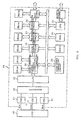
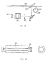
- output signals of the CCD image sensor 15 are fed to an image processing circuit 19.
- this image processing circuit 19 is comprised of a correlated double sampling (CDS) circuit 21 for reducing noise components which are included in the output signals for the respective colors of R, G, and B; a multiplexer 22 for selecting and outputting one of the signals of the respective colors of R, G, and B; and an A/D converter 23 for converting an analog signal outputted from the multiplexer 22 into a digital signal.
- CDS correlated double sampling
- the image processing circuit 19 is provided with a central processing unit (CPU) 24, and connected to a system bus extending from the CPU 24 are various circuits including an image correction circuit 25, a color correction circuit 26, an enlarging/reducing circuit 27; a binarization circuit 28; and a light-source controlling circuit 29.
- a dynamic random access memory (DRAM) and a static random access memory (SRAM) which are attached to each circuit are used as temporary memories, work files, or the like when predetermined processing is effected in each of the circuits.
- a read only memory (ROM) 31 stores, among others, a program which provides for processing procedures of the image reading apparatus.
- the image correction circuit 25 effects shading correction processing and gamma correction processing.
- the shading correction is correction for uniformalizing the distribution of the quantity of light in the longitudinal direction of the lamp, as is well known. Specifically, an initial light-quantity distribution in the longitudinal direction which is peculiar to the lamp is stored in advance, and an image signal outputted from the A/D converter 23 is corrected in correspondence with each position in the longitudinal direction. Further, in this image correction circuit 25, by sampling a CCD output when dark with the lamp turned off, it becomes possible to eliminate the nonuniformity of the CCD output when dark.
- the gamma correction is correction which is effected to correct the gamma characteristic peculiar to an image reading apparatus or the like, i.e., the characteristic that an output gradation value becomes nonlinear with respect to an input gradation value, as is also well known. Specifically, correction is made by, for example, multiplying the gradation value of an image signal outputted from the A/d converter 23 by an appropriate coefficient for each gradation value.
- the color correction circuit 26 corrects data on the respective colors of R, G, and B appropriately such that the data on the respective colors of R, G, and B outputted from the image reading apparatus will match the output characteristic of a device which is connected in a following stage.
- the enlarging/reducing circuit 27 enlarges or reduces the size of the image which has been read from the original 7 in accordance with the operator's desire.
- the binarization circuit 28 converts the image data of, for example, 256 gradation values outputted from the A/D converter 23 into image data of two gradation values of on and off in such a manner as to match the output characteristic of the device in the following stage.
- the image data of two gradation values prepared as described above is transformed into a command system for a SCSI interface, and is then fed to an image output unit of a host computer or a printer in the following stage.
- various signals which are fed to the host computer or the printer other than the image data are transformed into the command system for a bidirectional parallel interface, and are then sent to an operation control unit of the host computer or the printer in the following stage.
- the light-source controlling circuit 29 effects various control concerning the light source, i.e., the lamp 3
- the light-source controlling circuit 29 turns on and off the supply of power to the electrodes 2a and 2b of the lamp 3, and controls the intensity of light from the lamp 3 such that the light intensity becomes uniform with respect to the vertical scanning direction (i.e., the moving direction of the carriage 9 shown by arrow C in Fig. 1).
- the control of the light intensity concerning the vertical scanning direction can be executed by, for example, sampling the light intensity at each position when the lamp 3 moves in the vertical scanning direction by means of a photosensor (or a photosensor 66 which will be described later) provided at an appropriate position at the original table glass 8, and by adjusting the rate of amplification of an amplification circuit for the CCD image sensor 15 on the basis of the result of that sampling, or by controlling the supply of power to the lamp 3.
- a photosensor or a photosensor 66 which will be described later
- a voltage is applied across the electrodes 2a and 2b of the lamp unit 6 in Figs. 3 and 4, and electrons are emitted from the respective electrodes on the basis of the field emission.
- an ac voltage is applied across the electrodes 2a and 2b, so that the electrodes alternately act as cathodes and emit electrons.
- a dc power source it is also possible to use either one of them constantly as a cathode. Since the principle of generation of light in the lamp 3 is conventionally well known, a detailed description will be omitted.
- the overall surface of the original 7 is read by the CCD image sensor 15 by the above-described reading in the horizontal scanning direction and the vertical scanning direction.
- the read processing of one original 7 is normally completed in three minutes or thereabouts.
- the image data which has been read is subjected to various processing including the shading correction processing, gamma correction processing, color correction processing, enlarging/reducing processing, and binarization processing by the image processing circuit 19 shown in Fig. 5, and is then fed to the host computer or the like.
- Fig. 12 is a graph which three-dimensionally shows the manner of change over time of the rate of change in the quantity of light from the light source and the difference in the rate of change in the quantity of light.
- the rate of change in the quantity of light is taken as the X-axis
- the time is taken as the Y-axis
- the axial direction, i.e., the horizontal scanning direction, of the lamp (56) is taken as the Z-axis, as described before.
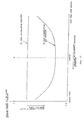
- FIG. 13 is a graph which shows the manner of change in the temperature of the tube wall of each lamp in a case where a lamp of the outer-surface electrode type was prepared which was provided with the heat-accumulating means (or the heat-accumulating member) and the same lamp was prepared which was not provided with the heat-accumulating means (or the heat-accumulating member), and these lamps were repeatedly turned on for three minutes and turned off for a predetermined time.
- the reason that the lighting time was set to three minutes is because in a case where one original is read by the image reading apparatus, the lighting time of three minutes or thereabouts is generally required, as described above.
- the maximum temperature of the tube wall temperature of the gas-filled tube 1 in a time duration required for reading, e.g., three minutes, becomes lower, and its minimum temperature becomes higher (the amount of change D2 in the tube wall temperature after the lamp provided with the heat-accumulating member (curve F) is lit for three minutes becomes substantially smaller than the amount of change D1 in the tube wall temperature after the lamp not provided with the heat-accumulating member (curve E) is lit for three minutes).
- the amount of change in the tube wall temperature of the gas-filled tube 1 becomes small by the provision of the heat-accumulating steel plate 18 and the like.
- the rate of change in the quantity of light in the time duration (about three minutes) required for reading can be reduced to 1/2 or thereabouts.
- the fact that the rate of change ⁇ 1 in the quantity of light is reduced naturally means that the difference ⁇ 2 in the rate of change in the quantity of light is also reduced.
- the distribution of the quantity of light in the longitudinal direction of the lamp unit 6 changes from B1 to B2 as shown in Fig.
- both the rate of change ⁇ 1 in the quantity of light and the difference ⁇ 2 in the rate of change in the quantity of light are reduced. If both the rate of change ⁇ 1 in the quantity of light and the difference ⁇ 2 in the rate of change in the quantity of light become small, it is possible to read the entire region from the beginning to the end of the reading of the original 7 with a uniform quantity of light, so that the density of the image which is reproduced after reading becomes uniform, thereby making it possible to reproduce an image faithful to the image of the original 7.
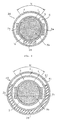
- Fig. 6 is a cross-sectional view illustrating a second arrangement of the lamp unit.
- This lamp unit 36 uses a heat-accumulating steel plate 38 as the heat-accumulating means, and this heat-accumulating steel plate 38 is not provided on the outer peripheral surface of the cladding tube 4, but is bonded to the outer peripheral surface of the gas-filled tube 1 at a position where the heat-accumulating steel plate 38 does not come into contact with the pair of electrodes 2a and 2b.
- the heat-accumulating steel plate 38 may be directly bonded to the gas-filled tube 1, or may be bonded thereto via the silicone rubber. In the first arrangement shown in Fig.
- the gas-filled tube 1 is covered with the cladding tube 4 to form a light-emitting tube, and the silicone rubber 17 and the heat-accumulating steel plate 18, which serve as the heat-accumulating means, are subsequently fitted over the outer peripheral surface of the light-emitting tube.
- the lamp unit with the heat-accumulating steel plate 38 incorporated therein is completed at a point of time when the gas-filled tube 1 is covered with the cladding tube 4.
- Fig. 7 is a cross-sectional view illustrating a third arrangement of the lamp unit.
- This lamp unit 46 uses the heat-accumulating steel plate 38 as the heat-accumulating means, and this heat-accumulating steel plate 38 is secured to the outer peripheral surface of the cladding tube 4. Then, the periphery of the secured heat-accumulating steel plate 38 is further surrounded by a sheathing tube 41 so as to hold the heat-accumulating steel plate 38 reliably.
- the sheathing tube 41 is formed of a transparent synthetic resin or glass. According to such a lamp unit 46, a space S1 between the cladding tube 4 and the sheathing tube 41 as well as the sheathing tube 41 itself also serve as the heat-accumulating means.
- silicone rubber or a laminated member formed by the heat-accumulating steel plate and the silicone rubber may be used.
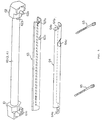
- Fig. 8 is a diagram which simultaneously show a perspective view illustrating a first embodiment of the lamp unit in accordance with the present invention and a partially enlarged view thereof;
- Fig. 9 is an exploded perspective view;
- Fig. 10 is a cross-sectional view.
- reference numeral 60 denotes a light-emitting member, and the lamp 3 or a lamp in which the lamp 3 is surrounded by the cladding tube 4 may be used.
- Reference numerals 61 and 62 denote holders, which hold opposite ends of the light-emitting member 60 (i.e., the lamp 3 or the like).
- Reference numeral 63 denotes a heat-accumulating sheet made of silicone rubber and serving as a heat-accumulating member, and this heat-accumulating sheet 63 is provided in contact with the outer peripheral surface of the light-emitting member 60.
- This heat-accumulating sheet 63 is formed in advance into a C-shaped cross-sectional configuration so as to improve the attachability and the characteristic of close contact with respect to the light-emitting member 60.
- Reference numeral 64 denotes a heat-accumulating metal plate having a C-shaped cross section and serving as a heat-accumulating member, and this heat-accumulating metal plate 64 is provided in contact with the outer peripheral surface of the heat-accumulating sheet 63.
- the heat-accumulating metal plate 64 may be formed from the same material as that of the aforementioned heat-accumulating steel plate 18.
- the heat-accumulating sheet 63 and the heat-accumulating metal plate 64 have substantially the same length as that of the light-emitting member 60 and, to be more precise, has a length which is slightly shorter (shorter by 1 to 3 mm or thereabouts) than an exposed portion of the light-emitting member 60 which is held by the holders 61 and 62. Additionally, light-quantity measuring holes 63c and 64c are provided in the heat-accumulating sheet 63 and the heat-accumulating metal plate 64.
- Reference numerals 65, 65 denote fastening belts made of a synthetic resin, and the heat-accumulating sheet 63 and the heat-accumulating metal plate 64 are attached to the light-emitting member 60 by means of these fastening belts 65, 65. Notched portions 64a, 64a are partially formed in the heat-accumulating metal plate 64 at positions where the fastening belts 65 are wound.
- a positioning portion 62b formed in the shape of a projection for determining the position where the heat-accumulating sheet 63 and the heat-accumulating metal plate 64 are attached is provided integrally on an inner side surface of one holder 62 of the pair of holders. Meanwhile, positioning recessed portions 63b and 64b which fit to the aforementioned positioning portion 62b are formed in one side ends of the heat-accumulating sheet 63 and the heat-accumulating metal plate 64.
- the pair of holders 61 and 62 are provided with pins 61a and 62a for positioning when this lamp unit is mounted inside the light-shielding plate 12 in the image reading apparatus shown in Fig. 1.
- Such a lamp unit can be easily assembled simply by applying the heat-accumulating sheet 63 and the heat-accumulating metal plate 64 to the light-emitting member 60 such that their recessed portions 63b and 64b fit to the positioning portion 62b of the holder 62, and by fastening the fastening belts 65, 65.
- the heat-accumulating sheet 63 and the heat-accumulating metal plate 64 are formed into C-shaped cross-sectional configurations, the heat-accumulating sheet 63 and the heat-accumulating metal plate 64 can be easily-applied to the light-emitting member 60, and the fastening operation of the fastening belts 65 is also facilitated.
- the illuminating range H of the light-emitting member 60 is determined by side edge portions 63d, 63d of the heat-accumulating sheet 63, as shown in Fig. 10.
- the lamp 3 of the outer-surface electrode type shown in Figs. 3 and 4 was prepared.
- the silicone rubber 17 and the heat-accumulating steel plate 18 were fitted to the lamp to form the lamp unit, as shown in Figs. 3 and 4, and this was set as a sample A.
- alumina was mixed in the silicone rubber 17.
- the lamp unit of this sample A was lit up, and measurement was made of the rate of change in the quantity of light at each position in the longitudinal direction of the lamp unit (i.e., in the horizontal scanning direction) three minutes after lighting-up.
- the silicone rubber 17 and the heat accumulating steel plate 18 were removed from the lamp unit of the sample A to obtain only the lamp, and this was set as a sample B.
- the lamp of this sample B was lit up, and the rate of change in the quantity of light at the same positions as the above three minutes after the lighting-up were measured.
- another lamp was prepared, and the same experiment as the above was conducted.
- the two samples A and the two samples B were averaged, and were set as the results of the experiment.
- the abscissa shows the position in the longitudinal direction of the lamp unit (i.e., the horizontal scanning direction).
- the broken line P shows a central portion in the longitudinal direction of the lamp unit.
- the ordinate of the graph shows the rate of change in the quantity of light three minutes after lighting-up, and shows that the rate of change in the quantity of light is greater from the upper toward the lower position.
- the curve B heat accumulation not provided shows the rate of change in the quantity of light from the lamp (sample B) to which the heat-accumulating means, i.e., the silicone rubber and the heat-accumulating steel plate, is not fitted.
- the line A shows the rate of change in the quantity of light from the lamp unit (sample A) in which the heat-accumulating means is fitted to the same lamp.
- the rate of change in the quantity of light is about half or thereabouts in the case where the heat-accumulating means is provided as compared to the case where it is not.
- the difference in the rate of change in the quantity of light is substantially zero. That is, in terms of the rate of change in the quantity of light in the horizontal scanning direction, it can be appreciated that the rate of change in the quantity of light in the longitudinal direction (i.e., the horizontal scanning direction) is substantially uniform in the case of the sample A in which the heat-accumulating means is employed.
- a comparison between these results and the results of the experiment shown in Fig. 12 shows that the mixture of alumina in the silicone rubber is very effective.
- This feature is a characteristic which is very desirable when the change in the quantity of light from the lamp is electrically corrected. If a description is given in greater detail, in a case where shading correction is effected also in the vertical scanning direction by monitoring a white reference provided in the vertical scanning direction so as to electrically correct the change in the quantity of light from the lamp in the vertical scanning direction by this shading correction, by the use of the above-described "heat-accumulating means," if the two points of
- any one of the lamp units in accordance with the present invention makes it possible to substantially reduce both the rate of change in the quantity of light over time after the lighting up of the lamp and the difference in the rate of change in the quantity of light.
- the change in the quantity of light from the start to the end of the reading of the original is reduced substantially, thereby making it possible to faithfully reproduce the image of the original over the overall surface in its longitudinal direction.
Landscapes
- Engineering & Computer Science (AREA)
- Multimedia (AREA)
- Signal Processing (AREA)
- Physics & Mathematics (AREA)
- Electromagnetism (AREA)
- Plasma & Fusion (AREA)
- Facsimile Scanning Arrangements (AREA)
- Light Sources And Details Of Projection-Printing Devices (AREA)
- Vessels And Coating Films For Discharge Lamps (AREA)
Claims (11)
- Lampeneinheit, umfassend:eine Lampe (60) mit einer gasgefüllten Hohlzylinderröhre, in die ein Gas gefüllt ist, und mit einem Paar von Elektroden, die an gegenüber liegenden Endabschnitten der gasgefüllten Röhre bereitgestellt sind, dadurch gekennzeichnet, dass sie des Weiteren ein Wärmeansammlungsmittel umfasst, um darin Wärme von der Lampe anzusammeln, wobei das Wärmeansammlungsmittel Silikongummi (63) umfasst, der um eine äußere Umfangsfläche der Lampe und in Kontakt mit derselben im Wesentlichen entlang der Länge der Lampe bereitgestellt ist, sowie ein metallisches Element (64), das um eine äußere Umfangsfläche des Silikongummis und in Kontakt mit diesem im Wesentlichen entlang der Länge des Silikongummis bereitgestellt ist.
- Lampeneinheit gemäß Anspruch 1, wobei der Silikongummi ein Blatt ist;das metallische Element eine metallische Platte mit einem C-förmigen Querschnitt ist; unddas Silikongummiblatt und die metallische Platte an der Lampe durch Befestigungsriemen angebracht sind.
- Lampeneinheit gemäß Anspruch 2, wobei gekerbte Abschnitte jeweils teilweise in der metallischen Platte an Positionen ausgebildet sind, wo die Befestigungsriemen herumgeschlungen werden.
- Lampeneinheit gemäß Anspruch 1 oder Anspruch 2, wobei das Wärmeansammlungsmittel mit C-förmiger Querschnittsform im Wesentlichen über einen gesamten Längsbereich der Lampe bereitgestellt ist, wodurch ein Beleuchtungsbereich der Lampe bestimmt wird.
- Lampeneinheit gemäß einem der vorhergehenden Ansprüche, wobei das Wärmeansammlungsmittel mit einem Loch zum Messen der Lichtmenge versehen ist.
- Lampeneinheit gemäß einem der vorhergehenden Ansprüche, des Weiteren umfassend eine Lampenhalterung zum Halten wenigstens eines Endabschnittes der Lampe, wobei die Lampenhalterung mit einem Positionierabschnitt zum Bestimmen einer Position, wo das Wärmeansammlungsmittel befestigt ist, versehen ist.
- Lampeneinheit gemäß einem der vorhergehenden Ansprüche, wobei Aluminiumoxid in den Silikongummi gemischt ist.
- Bildlesevorrichtung, umfassend: eine Lichtquelle zum Aussenden von Licht zum Beleuchten eines Originals; und einen Bildsensor zum Empfangen eines Lichtbildes von dem Original und Bereitstellen eines Ausgangs als ein elektrisches Signal, wobei die Lichtquelle durch eine Lämpeneinheit gemäß einem der Ansprüche 1 bis 7 gebildet wird.
- Bildlesevorrichtung gemäß Anspruch 8, wobei die Lampe nach Beendigung der Beleuchtung zum Lesen des Originals abgeschaltet wird.
- Bildlesevorrichtung gemäß Anspruch 8 oder Anspruch 9, wobei die Lampeneinheit eine Lampeneinheit gemäß Anspruch 5 ist und ein Photosensor an einer Position vorgesehen ist, die dem Loch zum Messen der Lichtmenge gegenüber liegt.
- Bildlesevorrichtung gemäß einem der Ansprüche 8 bis 10, wobei die Lampeneinheit eine Lampeneinheit gemäß Anspruch 6 ist und die Lampenhalterung das Positionierelement zum Bestimmen einer Befestigungsposition der Lampeneinheit darstellt.
Applications Claiming Priority (5)
| Application Number | Priority Date | Filing Date | Title |
|---|---|---|---|
| JP28169795 | 1995-10-30 | ||
| JP28169795 | 1995-10-30 | ||
| JP22308196 | 1996-08-06 | ||
| JP22308196A JP3803432B2 (ja) | 1995-10-30 | 1996-08-06 | ランプユニット及びこれを用いた画像読み取り装置 |
| EP96935468A EP0803899B1 (de) | 1995-10-30 | 1996-10-28 | Leuchte und diese benutzender bildleser |
Related Parent Applications (2)
| Application Number | Title | Priority Date | Filing Date |
|---|---|---|---|
| EP96935468A Division EP0803899B1 (de) | 1995-10-30 | 1996-10-28 | Leuchte und diese benutzender bildleser |
| EP96935468A Division-Into EP0803899B1 (de) | 1995-10-30 | 1996-10-28 | Leuchte und diese benutzender bildleser |
Publications (2)
| Publication Number | Publication Date |
|---|---|
| EP0989588A1 EP0989588A1 (de) | 2000-03-29 |
| EP0989588B1 true EP0989588B1 (de) | 2003-09-03 |
Family
ID=26525263
Family Applications (2)
| Application Number | Title | Priority Date | Filing Date |
|---|---|---|---|
| EP99204253A Expired - Lifetime EP0989588B1 (de) | 1995-10-30 | 1996-10-28 | Lampe und entsprechende Bildlesevorrichtung |
| EP96935468A Expired - Lifetime EP0803899B1 (de) | 1995-10-30 | 1996-10-28 | Leuchte und diese benutzender bildleser |
Family Applications After (1)
| Application Number | Title | Priority Date | Filing Date |
|---|---|---|---|
| EP96935468A Expired - Lifetime EP0803899B1 (de) | 1995-10-30 | 1996-10-28 | Leuchte und diese benutzender bildleser |
Country Status (6)
| Country | Link |
|---|---|
| US (1) | US6222647B1 (de) |
| EP (2) | EP0989588B1 (de) |
| JP (1) | JP3803432B2 (de) |
| DE (2) | DE69626001T2 (de) |
| TW (1) | TW385058U (de) |
| WO (1) | WO1997016845A1 (de) |
Families Citing this family (9)
| Publication number | Priority date | Publication date | Assignee | Title |
|---|---|---|---|---|
| JPH1141394A (ja) * | 1997-07-15 | 1999-02-12 | Canon Inc | 凹凸情報読み取り装置及び画像読み取り装置 |
| JPH11346293A (ja) * | 1998-06-01 | 1999-12-14 | Nec Corp | 光源固定部品及び原稿読取装置 |
| DE19926556A1 (de) * | 1999-06-11 | 2000-12-14 | Mannesmann Vdo Ag | Beheizbare Entladungslampe |
| DE10048409A1 (de) * | 2000-09-29 | 2002-04-11 | Patent Treuhand Ges Fuer Elektrische Gluehlampen Mbh | Entladungslampe mit kapazitiver Feldmodulation |
| EP1415325A1 (de) * | 2001-08-02 | 2004-05-06 | Koninklijke Philips Electronics N.V. | Niederdruckgasentladungslampe |
| JP3705593B2 (ja) * | 2002-05-27 | 2005-10-12 | Necアクセステクニカ株式会社 | 画像読取装置 |
| US20040095620A1 (en) * | 2002-11-19 | 2004-05-20 | Fang Lin | Flat bed scanner |
| US6872909B2 (en) * | 2003-04-16 | 2005-03-29 | Applied Science And Technology, Inc. | Toroidal low-field reactive gas and plasma source having a dielectric vacuum vessel |
| US8384405B2 (en) * | 2011-04-20 | 2013-02-26 | Tdk Corporation | Method for performing burn-in test |
Family Cites Families (15)
| Publication number | Priority date | Publication date | Assignee | Title |
|---|---|---|---|---|
| US3668456A (en) * | 1970-08-28 | 1972-06-06 | Sylvania Electric Prod | Lamp having improved press seal |
| GB1399260A (en) * | 1972-12-21 | 1975-07-02 | English Electric Valve Co Ltd | Magnetrons |
| SU817802A1 (ru) * | 1978-10-02 | 1981-03-30 | Предприятие П/Я М-5907 | Металлогалогенна лампа |
| JPS55165564A (en) * | 1979-06-11 | 1980-12-24 | Toshiba Corp | Metallic vapor discharge lamp |
| JPS612254A (ja) * | 1984-06-13 | 1986-01-08 | Toshiba Corp | けい光ランプ装置 |
| JPS62195847A (ja) * | 1986-02-24 | 1987-08-28 | Matsushita Electric Ind Co Ltd | 照明装置 |
| JPS6421960A (en) | 1987-07-16 | 1989-01-25 | Nec Corp | Static induction transistor |
| JPS6427157A (en) * | 1987-07-23 | 1989-01-30 | Toshiba Corp | Fluorescent lamp |
| JPS6421960U (de) * | 1987-07-30 | 1989-02-03 | ||
| US5258857A (en) * | 1988-05-16 | 1993-11-02 | Seiko Epson Corporation | Image input device and method for reading a picture image |
| DE4230814A1 (de) * | 1992-09-15 | 1994-03-17 | Patent Treuhand Ges Fuer Elektrische Gluehlampen Mbh | Hochdruckentladungslampe |
| JP2744389B2 (ja) * | 1992-10-06 | 1998-04-28 | キヤノン株式会社 | 原稿照明装置 |
| JPH07123213A (ja) * | 1993-10-21 | 1995-05-12 | Ricoh Co Ltd | 照光ランプ |
| JPH07123214A (ja) * | 1993-10-22 | 1995-05-12 | Hitachi Ltd | イメージスキャナ |
| US5710485A (en) * | 1995-11-13 | 1998-01-20 | Osram Sylvania Inc. | Neon lamp assembly with RF noise shield |
-
1996
- 1996-08-06 JP JP22308196A patent/JP3803432B2/ja not_active Expired - Fee Related
- 1996-10-28 US US08/860,684 patent/US6222647B1/en not_active Expired - Lifetime
- 1996-10-28 EP EP99204253A patent/EP0989588B1/de not_active Expired - Lifetime
- 1996-10-28 WO PCT/JP1996/003146 patent/WO1997016845A1/ja not_active Ceased
- 1996-10-28 EP EP96935468A patent/EP0803899B1/de not_active Expired - Lifetime
- 1996-10-28 DE DE69626001T patent/DE69626001T2/de not_active Expired - Lifetime
- 1996-10-28 DE DE69629851T patent/DE69629851T2/de not_active Expired - Lifetime
- 1996-11-05 TW TW085216927U patent/TW385058U/zh not_active IP Right Cessation
Also Published As
| Publication number | Publication date |
|---|---|
| TW385058U (en) | 2000-03-11 |
| EP0989588A1 (de) | 2000-03-29 |
| DE69629851D1 (de) | 2003-10-09 |
| WO1997016845A1 (en) | 1997-05-09 |
| DE69626001D1 (de) | 2003-03-06 |
| EP0803899B1 (de) | 2003-01-29 |
| JP3803432B2 (ja) | 2006-08-02 |
| EP0803899A4 (de) | 1998-08-19 |
| US6222647B1 (en) | 2001-04-24 |
| EP0803899A1 (de) | 1997-10-29 |
| DE69629851T2 (de) | 2004-07-15 |
| JPH09185954A (ja) | 1997-07-15 |
| DE69626001T2 (de) | 2004-01-08 |
Similar Documents
| Publication | Publication Date | Title |
|---|---|---|
| EP0989588B1 (de) | Lampe und entsprechende Bildlesevorrichtung | |
| EP0963103B1 (de) | Bildlesevorrichtung, und Dimmersteuerungsverfahren sowie Zeilensensorentwurf dafür | |
| US5140221A (en) | Rare gas cold cathode discharge tube and image input device | |
| US20020140996A1 (en) | Optical image scanner using pre-scan and post-scan compensation for illumination nonuniformity | |
| JP3509551B2 (ja) | 外部電極型放電ランプによる光源装置 | |
| US6621218B1 (en) | Line light source and image sensor using the same | |
| JP3576661B2 (ja) | 希ガス放電灯 | |
| EP0559913A1 (de) | Bildleser | |
| JP3492842B2 (ja) | 画像読取り装置 | |
| US5258857A (en) | Image input device and method for reading a picture image | |
| JPH06225077A (ja) | 画像入力装置 | |
| JP2000032236A (ja) | 画像読取り装置および画像読取り方法 | |
| EP0342607B1 (de) | FARBBILD-EINGABE-EINHEIT MIT EDELGAS-KALTKATHODEN-ENTLADUNGSRöHRE | |
| JPH1198331A (ja) | 画像照射装置とこれを用いる画像読取装置 | |
| JP2000151917A (ja) | 画像読取装置、異常検知方法、及び記憶媒体 | |
| JPH06217075A (ja) | 画像入力装置 | |
| JPH09120704A (ja) | 放電灯装置及び原稿照射装置 | |
| JPH06217076A (ja) | 画像入力装置 | |
| JP3346275B2 (ja) | 外部電極形蛍光ランプ | |
| JP2000209399A (ja) | 画像読取装置 | |
| JPH04248244A (ja) | 照明装置及び画像入力装置 | |
| JP3472147B2 (ja) | 画像読取り装置および画像読取り方法 | |
| JPH05227377A (ja) | 原稿照明用光源 | |
| JPH01240069A (ja) | カラー画像読取装置 | |
| JP2003348297A (ja) | 密着型イメージセンサ及び画像読取装置 |
Legal Events
| Date | Code | Title | Description |
|---|---|---|---|
| PUAI | Public reference made under article 153(3) epc to a published international application that has entered the european phase |
Free format text: ORIGINAL CODE: 0009012 |
|
| 17P | Request for examination filed |
Effective date: 20000105 |
|
| AC | Divisional application: reference to earlier application |
Ref document number: 803899 Country of ref document: EP |
|
| AK | Designated contracting states |
Kind code of ref document: A1 Designated state(s): DE FR GB |
|
| AX | Request for extension of the european patent |
Free format text: AL;LT;LV;RO;SI |
|
| AKX | Designation fees paid |
Free format text: DE FR GB |
|
| 17Q | First examination report despatched |
Effective date: 20020626 |
|
| GRAH | Despatch of communication of intention to grant a patent |
Free format text: ORIGINAL CODE: EPIDOS IGRA |
|
| GRAS | Grant fee paid |
Free format text: ORIGINAL CODE: EPIDOSNIGR3 |
|
| GRAA | (expected) grant |
Free format text: ORIGINAL CODE: 0009210 |
|
| AC | Divisional application: reference to earlier application |
Ref document number: 0803899 Country of ref document: EP Kind code of ref document: P |
|
| AK | Designated contracting states |
Kind code of ref document: B1 Designated state(s): DE FR GB |
|
| REG | Reference to a national code |
Ref country code: GB Ref legal event code: FG4D |
|
| REF | Corresponds to: |
Ref document number: 69629851 Country of ref document: DE Date of ref document: 20031009 Kind code of ref document: P |
|
| RIN2 | Information on inventor provided after grant (corrected) |
Inventor name: HIGUCHI, KENJI Inventor name: OHARA, TOSHIMITSU Inventor name: TADENUMA, HIRONOBU |
|
| ET | Fr: translation filed | ||
| PLBE | No opposition filed within time limit |
Free format text: ORIGINAL CODE: 0009261 |
|
| STAA | Information on the status of an ep patent application or granted ep patent |
Free format text: STATUS: NO OPPOSITION FILED WITHIN TIME LIMIT |
|
| 26N | No opposition filed |
Effective date: 20040604 |
|
| PGFP | Annual fee paid to national office [announced via postgrant information from national office to epo] |
Ref country code: FR Payment date: 20121018 Year of fee payment: 17 Ref country code: DE Payment date: 20121024 Year of fee payment: 17 |
|
| PGFP | Annual fee paid to national office [announced via postgrant information from national office to epo] |
Ref country code: GB Payment date: 20121024 Year of fee payment: 17 |
|
| GBPC | Gb: european patent ceased through non-payment of renewal fee |
Effective date: 20131028 |
|
| PG25 | Lapsed in a contracting state [announced via postgrant information from national office to epo] |
Ref country code: GB Free format text: LAPSE BECAUSE OF NON-PAYMENT OF DUE FEES Effective date: 20131028 |
|
| REG | Reference to a national code |
Ref country code: FR Ref legal event code: ST Effective date: 20140630 |
|
| REG | Reference to a national code |
Ref country code: DE Ref legal event code: R119 Ref document number: 69629851 Country of ref document: DE Effective date: 20140501 |
|
| PG25 | Lapsed in a contracting state [announced via postgrant information from national office to epo] |
Ref country code: DE Free format text: LAPSE BECAUSE OF NON-PAYMENT OF DUE FEES Effective date: 20140501 Ref country code: FR Free format text: LAPSE BECAUSE OF NON-PAYMENT OF DUE FEES Effective date: 20131031 |