EP0987697B1 - Support d'enregistrement - Google Patents
Support d'enregistrement Download PDFInfo
- Publication number
- EP0987697B1 EP0987697B1 EP99121452A EP99121452A EP0987697B1 EP 0987697 B1 EP0987697 B1 EP 0987697B1 EP 99121452 A EP99121452 A EP 99121452A EP 99121452 A EP99121452 A EP 99121452A EP 0987697 B1 EP0987697 B1 EP 0987697B1
- Authority
- EP
- European Patent Office
- Prior art keywords
- recording
- disc
- pulse
- information
- signal
- Prior art date
- Legal status (The legal status is an assumption and is not a legal conclusion. Google has not performed a legal analysis and makes no representation as to the accuracy of the status listed.)
- Expired - Lifetime
Links
Images


Classifications
-
- G—PHYSICS
- G11—INFORMATION STORAGE
- G11B—INFORMATION STORAGE BASED ON RELATIVE MOVEMENT BETWEEN RECORD CARRIER AND TRANSDUCER
- G11B7/00—Recording or reproducing by optical means, e.g. recording using a thermal beam of optical radiation by modifying optical properties or the physical structure, reproducing using an optical beam at lower power by sensing optical properties; Record carriers therefor
- G11B7/004—Recording, reproducing or erasing methods; Read, write or erase circuits therefor
- G11B7/0045—Recording
- G11B7/00456—Recording strategies, e.g. pulse sequences
-
- G—PHYSICS
- G11—INFORMATION STORAGE
- G11B—INFORMATION STORAGE BASED ON RELATIVE MOVEMENT BETWEEN RECORD CARRIER AND TRANSDUCER
- G11B20/00—Signal processing not specific to the method of recording or reproducing; Circuits therefor
- G11B20/10—Digital recording or reproducing
- G11B20/10009—Improvement or modification of read or write signals
- G11B20/10046—Improvement or modification of read or write signals filtering or equalising, e.g. setting the tap weights of an FIR filter
- G11B20/10194—Improvement or modification of read or write signals filtering or equalising, e.g. setting the tap weights of an FIR filter using predistortion during writing
-
- G—PHYSICS
- G11—INFORMATION STORAGE
- G11B—INFORMATION STORAGE BASED ON RELATIVE MOVEMENT BETWEEN RECORD CARRIER AND TRANSDUCER
- G11B20/00—Signal processing not specific to the method of recording or reproducing; Circuits therefor
- G11B20/10—Digital recording or reproducing
- G11B20/10009—Improvement or modification of read or write signals
- G11B20/10046—Improvement or modification of read or write signals filtering or equalising, e.g. setting the tap weights of an FIR filter
- G11B20/10212—Improvement or modification of read or write signals filtering or equalising, e.g. setting the tap weights of an FIR filter compensation for data shift, e.g. pulse-crowding effects
-
- G—PHYSICS
- G11—INFORMATION STORAGE
- G11B—INFORMATION STORAGE BASED ON RELATIVE MOVEMENT BETWEEN RECORD CARRIER AND TRANSDUCER
- G11B7/00—Recording or reproducing by optical means, e.g. recording using a thermal beam of optical radiation by modifying optical properties or the physical structure, reproducing using an optical beam at lower power by sensing optical properties; Record carriers therefor
- G11B7/004—Recording, reproducing or erasing methods; Read, write or erase circuits therefor
- G11B7/0045—Recording
-
- G—PHYSICS
- G11—INFORMATION STORAGE
- G11B—INFORMATION STORAGE BASED ON RELATIVE MOVEMENT BETWEEN RECORD CARRIER AND TRANSDUCER
- G11B7/00—Recording or reproducing by optical means, e.g. recording using a thermal beam of optical radiation by modifying optical properties or the physical structure, reproducing using an optical beam at lower power by sensing optical properties; Record carriers therefor
- G11B7/004—Recording, reproducing or erasing methods; Read, write or erase circuits therefor
- G11B7/005—Reproducing
-
- G—PHYSICS
- G11—INFORMATION STORAGE
- G11B—INFORMATION STORAGE BASED ON RELATIVE MOVEMENT BETWEEN RECORD CARRIER AND TRANSDUCER
- G11B7/00—Recording or reproducing by optical means, e.g. recording using a thermal beam of optical radiation by modifying optical properties or the physical structure, reproducing using an optical beam at lower power by sensing optical properties; Record carriers therefor
- G11B7/004—Recording, reproducing or erasing methods; Read, write or erase circuits therefor
- G11B7/006—Overwriting
- G11B7/0062—Overwriting strategies, e.g. recording pulse sequences with erasing level used for phase-change media
-
- G—PHYSICS
- G11—INFORMATION STORAGE
- G11B—INFORMATION STORAGE BASED ON RELATIVE MOVEMENT BETWEEN RECORD CARRIER AND TRANSDUCER
- G11B7/00—Recording or reproducing by optical means, e.g. recording using a thermal beam of optical radiation by modifying optical properties or the physical structure, reproducing using an optical beam at lower power by sensing optical properties; Record carriers therefor
- G11B7/007—Arrangement of the information on the record carrier, e.g. form of tracks, actual track shape, e.g. wobbled, or cross-section, e.g. v-shaped; Sequential information structures, e.g. sectoring or header formats within a track
- G11B7/00736—Auxiliary data, e.g. lead-in, lead-out, Power Calibration Area [PCA], Burst Cutting Area [BCA], control information
-
- G—PHYSICS
- G11—INFORMATION STORAGE
- G11B—INFORMATION STORAGE BASED ON RELATIVE MOVEMENT BETWEEN RECORD CARRIER AND TRANSDUCER
- G11B7/00—Recording or reproducing by optical means, e.g. recording using a thermal beam of optical radiation by modifying optical properties or the physical structure, reproducing using an optical beam at lower power by sensing optical properties; Record carriers therefor
- G11B7/007—Arrangement of the information on the record carrier, e.g. form of tracks, actual track shape, e.g. wobbled, or cross-section, e.g. v-shaped; Sequential information structures, e.g. sectoring or header formats within a track
- G11B7/0079—Zoned data area, e.g. having different data structures or formats for the user data within data layer, Zone Constant Linear Velocity [ZCLV], Zone Constant Angular Velocity [ZCAV], carriers with RAM and ROM areas
-
- G—PHYSICS
- G11—INFORMATION STORAGE
- G11B—INFORMATION STORAGE BASED ON RELATIVE MOVEMENT BETWEEN RECORD CARRIER AND TRANSDUCER
- G11B7/00—Recording or reproducing by optical means, e.g. recording using a thermal beam of optical radiation by modifying optical properties or the physical structure, reproducing using an optical beam at lower power by sensing optical properties; Record carriers therefor
- G11B7/12—Heads, e.g. forming of the optical beam spot or modulation of the optical beam
- G11B7/125—Optical beam sources therefor, e.g. laser control circuitry specially adapted for optical storage devices; Modulators, e.g. means for controlling the size or intensity of optical spots or optical traces
- G11B7/126—Circuits, methods or arrangements for laser control or stabilisation
-
- G—PHYSICS
- G11—INFORMATION STORAGE
- G11B—INFORMATION STORAGE BASED ON RELATIVE MOVEMENT BETWEEN RECORD CARRIER AND TRANSDUCER
- G11B7/00—Recording or reproducing by optical means, e.g. recording using a thermal beam of optical radiation by modifying optical properties or the physical structure, reproducing using an optical beam at lower power by sensing optical properties; Record carriers therefor
- G11B7/24—Record carriers characterised by shape, structure or physical properties, or by the selection of the material
- G11B7/26—Apparatus or processes specially adapted for the manufacture of record carriers
- G11B7/261—Preparing a master, e.g. exposing photoresist, electroforming
-
- G—PHYSICS
- G11—INFORMATION STORAGE
- G11B—INFORMATION STORAGE BASED ON RELATIVE MOVEMENT BETWEEN RECORD CARRIER AND TRANSDUCER
- G11B20/00—Signal processing not specific to the method of recording or reproducing; Circuits therefor
- G11B20/10—Digital recording or reproducing
- G11B20/12—Formatting, e.g. arrangement of data block or words on the record carriers
- G11B20/1217—Formatting, e.g. arrangement of data block or words on the record carriers on discs
-
- G—PHYSICS
- G11—INFORMATION STORAGE
- G11B—INFORMATION STORAGE BASED ON RELATIVE MOVEMENT BETWEEN RECORD CARRIER AND TRANSDUCER
- G11B20/00—Signal processing not specific to the method of recording or reproducing; Circuits therefor
- G11B20/10—Digital recording or reproducing
- G11B20/12—Formatting, e.g. arrangement of data block or words on the record carriers
- G11B2020/1264—Formatting, e.g. arrangement of data block or words on the record carriers wherein the formatting concerns a specific kind of data
- G11B2020/1265—Control data, system data or management information, i.e. data used to access or process user data
-
- G—PHYSICS
- G11—INFORMATION STORAGE
- G11B—INFORMATION STORAGE BASED ON RELATIVE MOVEMENT BETWEEN RECORD CARRIER AND TRANSDUCER
- G11B2220/00—Record carriers by type
- G11B2220/20—Disc-shaped record carriers
- G11B2220/25—Disc-shaped record carriers characterised in that the disc is based on a specific recording technology
- G11B2220/2537—Optical discs
-
- G—PHYSICS
- G11—INFORMATION STORAGE
- G11B—INFORMATION STORAGE BASED ON RELATIVE MOVEMENT BETWEEN RECORD CARRIER AND TRANSDUCER
- G11B7/00—Recording or reproducing by optical means, e.g. recording using a thermal beam of optical radiation by modifying optical properties or the physical structure, reproducing using an optical beam at lower power by sensing optical properties; Record carriers therefor
- G11B7/004—Recording, reproducing or erasing methods; Read, write or erase circuits therefor
- G11B7/0045—Recording
- G11B7/00454—Recording involving phase-change effects
-
- G—PHYSICS
- G11—INFORMATION STORAGE
- G11B—INFORMATION STORAGE BASED ON RELATIVE MOVEMENT BETWEEN RECORD CARRIER AND TRANSDUCER
- G11B7/00—Recording or reproducing by optical means, e.g. recording using a thermal beam of optical radiation by modifying optical properties or the physical structure, reproducing using an optical beam at lower power by sensing optical properties; Record carriers therefor
- G11B7/004—Recording, reproducing or erasing methods; Read, write or erase circuits therefor
- G11B7/006—Overwriting
-
- G—PHYSICS
- G11—INFORMATION STORAGE
- G11B—INFORMATION STORAGE BASED ON RELATIVE MOVEMENT BETWEEN RECORD CARRIER AND TRANSDUCER
- G11B7/00—Recording or reproducing by optical means, e.g. recording using a thermal beam of optical radiation by modifying optical properties or the physical structure, reproducing using an optical beam at lower power by sensing optical properties; Record carriers therefor
- G11B7/24—Record carriers characterised by shape, structure or physical properties, or by the selection of the material
- G11B7/2407—Tracks or pits; Shape, structure or physical properties thereof
- G11B7/24085—Pits
Definitions
- the present invention relates to a data recording medium.
- Data recording devices for optically recording information, and particularly digital data, to a storage medium are commonly used as a convenient means of mass data storage.
- Phase change optical discs are one type of optical data recording medium.
- a semiconductor laser emits an optical beam to a spinning disc to heat and melt a recording film on the disc.
- the achieved temperature and the cooling process (rate) of the molten film can be regulated by controlling the power of the laser beam, thereby inducing a phase change in the recording film.
- the recording film When laser power is high, the recording film cools rapidly from a high temperature state and thus becomes amorphous. When a relatively low power laser beam is emitted, the recording film cools gradually from a medium high temperature state, and thus crystallizes. The resulting amorphous parts of the recording film are commonly known as "marks," and the crystallized part between any two marks is known as a "space.” Two-value binary information can thus be recorded using these marks and spaces.
- the laser When a laser beam is emitted at a high power setting to form a mark, the laser is referred to as operating at "peak power.” When the laser is emitted at low power to form a space, the laser is said to operate at a "bias power" level.
- a laser beam is emitted at a power level low enough to not induce a phase change, and its reflection is then detected.
- Reflectivity from an amorphous mark is normally low, and is high from a crystalline space.
- a read signal can therefore be generated by detecting the difference in light reflected from the marks and spaces.
- Data can also be recorded to a phase change disc using a mark position recording method (also known as PPM) or a mark edge recording method (also known as PWM).
- Mark edge recording normally achieves a higher recording density.
- Mark edge recording typically records longer marks than recorded by the mark position recording method.
- heat accumulation in the recording film results in the mark width increasing radially to the disc towards the end part of the mark.
- this can result in part of a mark not being overwritten or completely erased, resulting in a significant loss of signal quality due to signal crosstalk between tracks during reproduction.
- Recording density can also be increased by shortening the lengths of the recorded marks and spaces, Thermal interference can occur when the spaces, in particular, are shortened beyond a certain point. This thermal interference can result in heat at the trailing edge of a recorded mark travelling through the following space, thus affecting heat distribution at the beginning of the next mark. Heat at the beginning of one recorded mark can also travel back through the preceding space and adversely affect the cooling process of the preceding mark. When such thermal interference occurs with conventional recording methods, the positions of the leading and trailing edges can shift, thus increasing the error rate during data reproduction.
- Japanese Unexamined Patent Application Publication (kokai) H07-129959 (U.S. Patent numbers 5,490,126 and 5,636,194) teaches a recording method whereby a signal for forming a mark in mark edge recording is analyzed into three parts, a constant width beginning part, a middle part having pulses with a constant period, and a constant width end part, and this signal is then used to drive recording by rapidly switching the output of a two-value laser beam during mark formation.
- the width of the middle part of a long mark is substantially constant and does not spread because laser output is driven with a constant period pulse current producing the minimum power required for mark formation. Jitter at the leading and trailing edges of the mark also does not increase during direct overwrite recording because a constant width laser beam is emitted to the leading and trailing end parts of the mark.
- Japanese Patent Application 5-279513 does not, however, teach a method for determining the optimum positions of the leading and trailing parts of a mark.
- the reliability of the optimized recording will be low. Furthermore, even if optimized recording is achieved, it will be at the expense of excessive time spent searching for the optimum position and excessive circuit cost.
- a method for changing the leading and trailing edge positions of a mark based on the data being recorded has also been invented as a means of achieving high density data recording.
- a problem with this method is that the edge of a recorded mark can move due to thermal interference as described above. Such edge movement is also highly dependent upon the disc format and the makeup of the recording film, and if either of these change even slightly, optimized recording cannot be achieved.
- EP-A-0 477 892 discloses the forming of a table containing shift values for different input patterns and for varying laser powers. For that purpose a text pattern is used. Shift values as a function of temperature or laser power are pre-recorded on the optical disc.
- EP-A-0 442 566 discloses an information recording device comprising write means for providing the record carrier with information patterns. Further, the principle of storing setting parameters in combination with identification data identifying the combination or recording device and medium for which the adjustment data has been determined is disclosed therein.
- an object of the present invention is to provide a data recording medium provided for easily determining the optimum positions of the leading and trailing edges of each mark, thereby achieving optimized recording, even when the disc format, recording film composition, and recording apparatus characteristics vary.
- a data recording medium having a plurality of concentric or spiral tracks for recording information represented as marks and spaces between the marks, the marks being formed by emitting to a track recording surface an optical beam modulated by a plurality of drive pulses where the drive pulse count is adjusted according to a length of a mark part in the original signal to be recorded to the track, said data recording medium comprises:
- Fig. 1 is a block diagram of an optical data recording apparatus, referred to below as an optical disc recorder, according to the preferred embodiment of the present invention.
- FIG. 1 Shown in Fig. 1 are: an optical disc 101, spindle motor 102, semiconductor laser 103, collimeter lens 104, beam splitter 105, objective lens 106, collective lens 107, photodetector 108, laser drive circuit 109, pulse moving circuit 110, pulse generator 111, preamplifier 112, low pass filter 113, reproduction equalizer 114, digitizing circuit 115, PLL 116, demodulation circuit 117, error correction circuit 118, power level setting circuit 119, pulse position offset measuring circuit 120, switch 121, switch contacts 122, 123, and 124, pattern signal generator 125 for pulse position adjusting, modulation circuit 126, recording data generator 127, read data signal 128, memory 129, memory 130, data comparator 131, and memory 132.
- the recording data generator 127 further comprises a unique pattern generator 127a, a random pattern generator 127b, and a real signal generator 127c.
- Fig. 1 Also shown in Fig. 1 are delay circuits 138 and 139, each having the same delay time, and an asymmetry detector 140.
- Memory 129 stores two tables which are corrected by the method of the present invention as shown in Fig. 5 with the corrected tables then written back to memory.
- Memory 132 stores information used for determining the power level used to drive the laser, and stores the final power setting selected. Note that in this exemplary embodiment of the present invention laser drive power is set to either the above-noted peak power level or bias power level.
- Memory 130 stores (1) disc-specific information that is prewritten to the optical disc (such as the name of the optical disc manufacturer, product number, manufacturing location, date of production, disc structure, and recording film composition), (2) the adjustment method as further described below, (3) the above-noted two tables corrected and stored in memory 129, and (4) the selected laser power level stored to memory 132. It is to be noted that memory 130 stores the above contents (1) to (4) for a plurality of different optical discs.
- FIG. 37 A conceptual map for the data layout in memory 130 is shown in Fig. 37.
- the above-noted content (1) is contained in disc-specific information n; content (2) and (3) is contained in the pulse position information; and content (4) is contained in the temporary power and operational power level information.
- a disc recorder When a disc is loaded in a recording device, referred to hereafter as a disc recorder, the disc-specific information is read immediately from the disc. The disc-specific information read from disc is then compared with the disc-specific information stored to memory 130 to determine whether the same information is already in memory.
- the disc-specific information, temporary power and operational power level information, and pulse position information are stored as one set of data to memory 130. It is to be noted that anywhere from several seconds to ten several seconds may be required to obtain the temporary power and operational power level information and pulse position information through a test recording operation as described herein.
- the temporary power and operational power level information and pulse position information for the data set matching the disc-specific information read from disc is read from memory 130.
- the temporary power and operational power level information is then written to memory 132 and the pulse position information is written to memory 129. It is to be noted that because this information can be simply read from memory, the several seconds to ten several seconds required to determine the information through a test recording operation is saved.
- n sets of disc-specific information, temporary power and operational power level information, and pulse position information will be written to memory 130.
- these n data sets are stored to two or more locations. By storing the data sets to a plurality of locations, the data can be reproduced from a second location, for example, if reading data from one location in memory 130 is disabled due to a scratch or contamination, for example.
- Fig. 2 is a plan view of the optical disc 101, which has a data storage area 201 and a writing test zone 202.
- the optical head of the data recorder shown in Fig. 1 comprises the semiconductor laser 103, collimator lens 104, beam splitter 105, objective lens 106, collective lens 107, and photodetector 108.
- the optical head moves to the writing test zone 202, which is used for determining the optimum positions for the start position and end position of each mark.
- This area for determining the optimum mark start and end positions is an area at the inside circumference area and/or the outside circumference area of the disc, and is outside of the user data recording area.
- An exemplary area is the drive test zone of the disc.
- Switch 121 switches contact 122 to contact 123 when writing to the writing test zone 202. During normal user data writing operations, the switch 121 changes so that contact 122 is conductive to contact 124 so that the output signal from the recording data generator 127 is applied to the pulse generator 111 after it has been modulated by the modulation circuit 126.
- the power level setting circuit 119 sets the laser drive circuit 109 to either peak power or bias power. At this time the output signal from pattern signal generator 125 is passed by switch 121 to the pulse generator 111. Signal flow from the pulse generator 111 is described further below with reference to Fig. 3.
- a first pattern signal 301 which is the output signal from the pattern signal generator 125; output signal 302 from the pulse generator 111; output signal 303 from the pulse moving circuit 110; and mark pattern 304 formed in the recording track of the optical disc 101 as a result of modulating laser power output between peak power and bias power levels according to output signal 303.
- signals 301, 302, and 303 are not generated on the same time base, for convenience they are shown with corresponding parts in each signal aligned vertically.
- mark parts 309, 311, 313, 315, 317, and 319 are the parts of the signal whereby a mark is to be formed on the disc, and space parts 310, 312, 314, 316, 318, and 320 are the parts of the signal that appear as a space on disc. It is further assumed below that mark part 309 follows space part 320 such that first pattern signal 301 comprises a repeating pattern of parts 309 to 320.
- mark part 309 is a 6T signal (a 6T mark part below), space part 310 is a 6T space, 311 is a 3T mark, 312 is a 6T space, 313 is a 6T mark, 314 is a 6T space, 315 is a 6T mark, 316 is a 4T space, 317 is a 6T mark, 318 is a 6T space, 319 is a 7T mark, and 320 is a 6T space.
- space part 310 is a 6T space
- 311 is a 3T mark
- 312 is a 6T space
- 313 is a 6T mark
- 314 is a 6T space
- 315 is a 6T mark
- 316 is a 4T space
- 317 is a 6T mark
- 318 is a 6T space
- 319 is a 7T mark
- 320 is a 6T space.
- a reproduction signal with a small dc component or low frequency component can be obtained when the marks and spaces are reproduced by inserting signals 319 and 320 whereby a DSV of substantially zero can be obtained; note that signals 319 and 320 are inserted only when DSV is otherwise not zero. Reproducing a signal with many dc components or low frequency components can result in the digitizing circuit 115 erroneously generating a signal with the wrong sequence of 0s and 1s.
- first pattern signal 301 is generated so that the sum (34T) of the periods of mark parts 309, 311, 313, 315, 317, and 319 is equal to the sum (34T) of the space parts 310, 312, 314, 316, 318, and 320.
- DSV is calculated by adding the periods of the mark parts as positive values and the periods of the space parts as negative values. As a result, the DSV of first pattern signal 301 is 0.
- This first pattern signal 301 is converted to a pulse sequence by the pulse generator 111, resulting in pulse generator output signal 302. Pulse output from the pulse generator 111 corresponding to marks of lengths from 3T to 11T is shown in Fig. 4.
- the pulse at the start of the signal is referred to as the first pulse 401
- the pulse at the end of the signal is the last pulse 404.
- the pulses between the first pulse 401 and last pulse 404 are referred to as multiple pulses 402 and 403, and have a constant period.
- a 4T mark therefore comprises only the first and last pulses, and has no multiple pulses 402 or 404 therebetween.
- a 3T mark comprises just one pulse.
- the time-base length of the first pulse is 1.5T
- the last pulse is 0.5T
- the length of the multiple pulses is also 0.5T.
- the invention shall not be so limited, however, and the length, count, or period of these pulses can be varied as necessary according to the structure of the optical disc 101.
- the pulse generator output signal 302 is input to the pulse moving circuit 110, which generates and outputs a signal 303 in which the positions of the first pulse and last pulse are moved.
- Fig. 5 shows the combinations of marks and spaces used for shifting the first pulse and last pulse positions.
- Fig. 5 (a) shows the pulse movement tables after correction by the method of this present invention
- Fig. 5 (b) shows the tables before correction.
- Symbols 3S3M, 4S3M, and so forth in the tables in Fig. 5 (a) are a type of address, and are indicative of the signal type as well as the value written to that address.
- the value 3S3M for example, represents a signal in which a 3T mark follows a 3T space.
- the value of the first pulse movement TF stored at the place indicated by 3S3M is the movement required when a 3T mark follows a 3T space.
- first pulse movement TF values are obtained by, for example, a trial and error process using a particular optical test disc, and the resulting values are compiled in the tables in Fig. 5 (a).
- the content of the completed table is stored for all optical discs having the same structure as the optical test disc.
- Predetermined initial values are stored in the table on the left in Fig. 5 (b) for the first pulse.
- the table on the right in Fig. 5 (b) stores the initial values before correcting last pulse movement.
- the position of the first pulse that is, first drive pulse position Tu
- the marks and spaces are separated into three groups, that is, 3T, 4T, and 5T or longer. A total of nine different pulse positions are therefore defined.
- the position of the last pulse that is, last drive pulse position Td, likewise changes according to the length of the mark and the immediately following space.
- the marks and spaces are separated into three groups, that is, 3T, 4T, and 5T or longer. A total of nine different pulse positions are therefore defined.
- Fig. 33 is an enlarged view of the 6T mark 317 in the first pattern signal 301 shown in Fig. 3, and the corresponding part in the pulse generator output signal 302.
- a 4T space 316 is immediately before the 6T mark 317.
- a 4T space followed by a 6T mark belongs to the 4S5M group in the left table in Fig. 5 (a). Correcting the initial first pulse movement TF stored for this group is described below.
- the pattern signal generator 125 in the optical data recorder shown in Fig. 1 generates a first pattern signal 301.
- This first pattern signal 301 is sent to the pulse generator 111, delay circuit 139, pulse position offset measuring circuit 120, and memory 129.
- the pulse position offset measuring circuit 120 also stores the first pattern signal 301, which is used for comparison with the reproduction signal during data reproduction.
- the pulse generator 111 generates the output signal 302 required for recording the pattern signal. Referring to the signals shown on the top two rows in Fig. 4, for example, the pulse generator 111 generates a first pulse 401 corresponding to the rising edge of the mark in the first pattern signal 301, then outputs multiple pulses 402 and 403, and last pulse 404.
- the pulse generator output signal 302 is delayed a predetermined period by the delay circuit 138, and then passed to the pulse moving circuit 110.
- This predetermined period is 13T in this exemplary embodiment
- the first pattern signal 301 is analyzed in memory 129 to determine to which of the 18 signal groups, that is, 3S3M, 3S4M, 3S5M, 4S3M, 4S4M, 4S5M, 5S3M, 5S4M, 5S5M, 3M3S, 4M3S, 5M3S, 3M4S, 4M4S, 5M4S, 3M5S, 4M5S, and 5M5S, the signal in the preceding 10T or longer period belongs.
- memory 129 detects that the signal belongs to the 4S5M group. Memory 129 therefore reads and outputs to the pulse moving circuit 110 the amount of movement stored in the table at 4S5M0.
- the initial 4S5M0 movement value is read from the table the first time a movement value is read.
- the pulse moving circuit 110 then moves the first pulse of the pulse generator output signal 302 supplied thereto after a predetermined delay based on the initial movement value read from 4S5M0.
- Movement of the first pulse is described in further detail below with reference to Fig. 1 and Fig. 33.
- the pulse moving circuit 110 When the pulse moving circuit 110 is notified by memory 129 that a pattern belonging to a specific group will soon arrive from the delay circuit 139, it also receives the first pulse movement TF for that pattern from the memory 129. For example, when the memory 129 informs the pulse moving circuit 110 that a pattern belonging to the 4S5M group, that is, a 4T space 316 following by a 6T mark 317, will arrive from the delay circuit 139, it also sends the first pulse movement TF read for the 4S5M0 group.
- the pulse moving circuit 110 then begins counting first pulse movement TF at the rising pulse edge of the 6T mark 317 received from the delay circuit 139, that is, at time R1 in Fig. 33. Output of the first pulse from the delay circuit 138 is delayed for the period counted by the pulse moving circuit 110, that is, for pulse movement TF.
- first pulse movement TF is referenced to the rising edge R1 of the first pattern signal 301, for example, first pulse movement TF is expressed as the time difference from reference time R1 as shown in Fig. 33. In this exemplary embodiment, pulse movement TF is approximately 3 ns. It is to be noted that the first pulse is moved without changing the pulse width.
- the pattern signal shown in Fig. 3 contains signal components belonging to four of the 18 groups in the table shown in Fig. 5 (a): type 3M5S in period 321, type 5S3M in period 322, type 4S5M in period 323, and type 5M4S in period 324. Each of the pulse signal components corresponding to these four types in first pattern signal 301 is therefore moved.
- the laser is then driven according to these moved pulses to record the actual marks.
- the resulting marks 304 are shown in Fig. 3.
- the first pattern signal 301 comprising elements 309 to 320 as shown in Fig. 3 is output repeatedly and recorded around one track.
- Reproduction includes converting an optical signal from the photodetector 108 to an electrical signal, and then processing this electrical signal with preamplifier 112, low pass filter 113, reproduction equalizer 114, and digitizing circuit 115 to obtain reproduction signal 305.
- the reproduction signal 305 is input to pulse position offset measuring circuit 120.
- the reproduction signal 305 from a single track is thus input repeatedly to the pulse position offset measuring circuit 120.
- the pulse position offset measuring circuit 120 thus reads each of the periods 321, 322, 323, and 324 associated with different signal types multiple times, and calculates the average for each period.
- the pulse position offset measuring circuit 120 compares the periods 321, 322, 323, 324 corresponding to the types obtained in the recorded first pattern signal 301 during recording, and the averages for the same periods obtained from the reproduction signal 305 to detect whether any shifting in pulse position has occurred. Using by way of example the signals recorded and reproduced as described above, the combined time of the 4T space 316 and 6T mark 317 in the first pattern signal 301 is compared with the average obtained for the corresponding period 324 in the reproduction signal 305, and the difference therebetween is obtained. If there is a difference, the pulse position offset measuring circuit 120 determines that the pulse position shifted, and the calculated difference is therefore sent to memory 129. Because this difference is the result of the initial movement value 4S5M0, this initial movement value 4S5M0 is increased or decreased in memory 129 according to the difference, thereby correcting the stored movement value. This corrected value is then overwritten to type 4S5M.
- the stored movement value is corrected and overwritten to 4S5M using a single feedback loop (through 110, 109, 108, 112, 115, 120, 126, 129) in the above exemplary embodiment. It will be obvious, however, that a plurality of feedback loops can be alternatively used to correct the value of the first pulse movement TF as shown in Fig. 33.
- Last pulse position movement changes according to the mark length and the length of the following space.
- marks and spaces are separated into three groups based on length, 3T, 4T, and 5T or longer, and pulse position movement is defined for each of the nine possible mark/space combinations.
- the last pulse movement TL is then calculated using the same method used to calculate first pulse movement TF.
- last pulse movement TL is corrected in the same manner as the first pulse movement TF described above.
- This last pulse movement TL is the time interval from time reference R2 offset 2T forward of the trailing edge of the mark to the trailing edge of the last pulse, and is corrected by means of the loop described above with reference to the first pulse.
- the last pulse movement TL is approximately 11 ns in this exemplary embodiment. It is to be also noted that the width of the last pulse does not change even though the amount of last pulse movement TL changes, and in this exemplary embodiment the pulse width remains the same with the pulse simply shifted on the time axis.
- types 4M5S, 5S4M, 3S5M, and 5M3S are corrected using a pattern signal 601 as shown in Fig. 6; types 4M4S, 3M3S, 4S4M, 3S3M are corrected using a pattern signal 701 as shown in Fig. 7; types 4M3S, 4S3M are corrected using a pattern signal 801 as shown in Fig. 8; and types 3M4S, 3S4M are corrected using a pattern signal 901 as shown in Fig. 9.
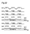
- types 5M5S and 5S5M can be corrected using a pattern signal 3201 as shown in Fig. 32, or a default value therefor can be simply " defined. It is to be noted that types 5M5S and 5S5M are preferably corrected before the other types. This is because these marks and spaces have the longest period and are therefore least affected by thermal interference. The delay period is therefore small, and can be used as a reference value for determining the other delay periods.
- a predetermined initial value is set as shown in Fig. 5 (b) before pattern signal recording. These initial values can be separately determined from experience, or they can be all set to the same value. If the same initial value is used for all, the value, for example, 1 ns, stored for the first pulse movement in a 5S5M pattern in the left table in Fig. 5 (b), for example, is preferably stored for all patterns. In the case of the right table in Fig. 5 (b), the value stored for 5M5S is used. Note, further, that in this case the value set for the 5S5M pattern is determined so, that the time between first pulse 401 and multiple pulse 402 is 0.5T as shown in Fig. 4, and the value set for 5M5S is determined so that the time between multiple pulse 403 and last pulse 404 is 0.5T.
- the pattern signal 3201 of the pattern signal generator 125 in this example has a single period of 6T. Also shown are output signal 3202 from the pulse generator 111; output signal 3203 from the pulse moving circuit 110; and marks 3204 formed in the recording track of the optical disc 101 as a result of modulating laser power output between peak power and bias power levels according to output signal 3203. It is to be noted that while signals 3201, 3202, and 3203 are not generated on the same time base, for convenience they are shown with corresponding parts in each signal aligned vertically.
- the pattern signal 3201 in this case represents marks and spaces with a simple 6T period, and thus contains types 5S5M and 5M5S of the eighteen pattern types shown in Fig. 5 (a).
- the laser is then driven based on drive signal 3203 in Fig. 32 to record the marks 3204.
- pattern signal 3201 in Fig. 32 is repeatedly recorded around one complete circumference of the recording track. When this track is recorded, it is then reproduced.
- Reproduction includes converting an optical signal from the photodetector 108 to an electrical signal, and then processing this electrical signal with preamplifier 112, low pass filter 113, and reproduction equalizer 114.
- the reproduction signal 3205 from the reproduction equalizer 114 is applied to asymmetry measuring circuit 140 and digitizing circuit 115.
- the digitizing circuit 115 adjusts the slice level signal 3209 so that the output level corresponding to a mark and the output level corresponding to a space in the output signal of the digitizing circuit are at equal intervals, and applies this slice level signal 3209 to the asymmetry measuring circuit 140.
- the asymmetry measuring circuit 140 compares the average of the high 3211 and low 3210 peak values of the reproduction signal 3205 with the slice level signal 3209. when the difference or ratio therebetween is outside a predetermined range of tolerance, the lengths of the marks 3204 and spaces are not equal. This difference is attributable to a shift in the first pulse and last pulse positions.
- Initial movement values 5S5M0 and 5M5S0 are therefore corrected according to the sign of the difference so that, for example, the first pulse and last pulse each move the same time-base distance in opposite directions. The corrected values are then overwritten to memory 129.
- the stored movement values are corrected and overwritten to 5M5S and 5S5M using a single feedback loop (through 110, 109, 108, 112, 115, 140, 129) in the above exemplary embodiment. It will be obvious, however, that a plurality of feedback loops can be alternatively used. As a result, 5S5M and 5M5S values whereby 6T marks can be recorded at the correct length can be obtained. By thus correcting the physical length of a mark used as a reference, marks in other groups can also be recorded at the correct length, and recording with less jitter can be achieved.
- the asymmetry information can likewise be recorded to area 1503 of the optical disc 1501 shown in Fig. 15 in addition to the optimum or typical leading and trailing mark edge positions recorded during manufacture. Generally, it is preferable to have a smaller amount of asymmetry value.
- the optimum asymmetry value slightly varies relatively to different discs due to, e.g., the structure of the recording film of the disc.
- the output signal 303 from the pulse moving circuit 110 is input to the laser drive circuit 109 whereby laser power is modulated so that the laser emits at peak power while output signal 303 is high, and emits at bias power while the signal is low, to form a mark sequence 304 as shown in Fig. 3.
- the collimator lens 104 converts the laser beam emitted from the semiconductor laser 103 to parallel light, which is then incident on the beam splitter 105.
- Light passing the beam splitter 105 is focused to a light spot by the objective lens 106, and emitted to the optical disc 101.
- Light reflected from the optical disc 101 is then collected by the objective lens 106, and passed back to the beam splitter 105.
- Light reflected by the beam splitter 105 is collected by collective lens 107, and focused on photodetector 108.
- the photodetector 108 converts light incident thereon to an electrical signal, which is then amplified by the preamplifier 112.
- the output signal from the preamplifier 112 is then passed through the low pass filter 113 whereby high frequency signal components are blocked.
- the reproduction equalizer 114 then equalizes the signal, which is next binarized by the digitizing circuit 115 using a predetermined slice level.
- a reproduction signal 305 converted to a sequence of 0s and Is is thus output from the digitizing circuit 115 to the pulse position offset measuring circuit 120.
- the pulse position offset measuring circuit 120 measures the interval between specific edges or measures edge interval jitter; in this exemplary embodiment the pulse position offset measuring circuit 120 measures the specific edge intervals 321, 322, 323, and 324 in the reproduction signal 305.
- the setting for last pulse movement 3M5S in Fig. 5 (a) is reduced by the difference between the measured interval 321 and the normal 9T interval from the current setting of 3M5S0 by way of bus 126.
- the setting for first pulse movement 5S3M in Fig. 5 (a) is similarly increased from the current 5S5M0 setting by the difference between the edge interval 322 and the normal 9T interval by way of bus 126 if the edge interval 322 is longer than the normal 9T interval.
- the values stored for 4S5M and 5M4S are likewise corrected based on the measured edge intervals 323 and 324.
- the first pattern signal 301 is again recorded and the edge intervals are measured. This process is repeated until the difference between the normal interval and the measured edge interval is below a predetermined threshold level simultaneously for all four edge intervals.
- a second pattern signal is recorded.
- second pattern signal 601 is the output signal from the pattern signal generator 125; output signal 602 from the pulse generator 111; output signal 603 from the pulse moving circuit 110; and mark pattern 604 formed in the recording track of the optical disc 101 based on output signal 603.
- the first pulse settings 5S4M and 3S5M, and last pulse settings 4M5S and 5M3S in Fig. 5 (a) are then updated using the same method described above using the first specific pattern signal 301.
- third pattern signal 701 which is the output signal from the pattern signal generator 125; output signal 702 from the pulse generator 111; output signal 703 from the pulse moving circuit 110; and mark pattern 704 formed in the recording track of the optical disc 101 based on output signal 703.
- the 10T period of 710 and 711 (a 6T space and 4T mark) and the 10T period of 712 and 713 (a 4T mark and 6T space 712 is a 4T SPACE and 713 is a 6T MARK in Fig. 7) overlap and appear as a continuous wave.
- Measured signal 710 - 711 and the next measured signal 712 - 713 therefore overlap, and it is difficult to accurately separate and analyze the measured signals.
- a jitter meter can therefore be substituted for measurement.
- the same method used with the first pattern is applied to set and update the first pulse settings 4S4M and 3S3M, and last pulse settings 4M4S and 3M3S in Fig. 5 (a).
- the conditions obtaining the least edge jitter with this third pattern signal and the correct edge interval time are the same. For example, if edge intervals 729 and 730 occur at the correct 9T time interval, jitter at a 9T edge interval will also be the lowest. Therefore, if either edge interval is offset from the normal 9T time, jitter at a 9T edge interval will increase.
- a fourth pattern signal is recorded.
- Shown in Fig. 8 are fourth pattern signal 801, which is the output signal from the pattern signal generator 125; output signal 802 from the pulse generator 111; output signal 803 from the pulse moving circuit 110; and mark pattern 804 formed in the recording track of the optical disc 101 based on output signal 803.
- the first pulse setting 4S3M and last pulse setting 4M3S in Fig. 5 (a) are updated using the same method used with the first pattern signal.
- a fifth pattern signal is recorded.
- Shown in Fig. 9 are fifth pattern signal 901, which is the output signal from the pattern signal generator 125; output signal 902 from the pulse generator 111; output signal 903 from the pulse moving circuit 110; and mark pattern 904 formed in the recording track of the optical disc 101 based on output signal 903.
- the first pulse setting 3S4M and last pulse setting 3M4S in Fig. 5 (a) are updated using the same method used with the fourth pattern signal.
- this preferred embodiment of the present invention records first through fifth specific test patterns to determine the pulse position offset whereby edge intervals occur at the correct time interval and jitter is minimized. It will be obvious to one with ordinary skill in the related art, however, that other specific test patterns or adjustment methods can be alternatively used insofar as the test recording enables the mark start and end positions to be determined according to the input signal.
- the first pulse setting 5S5M and last pulse setting 5M5S used for marks and spaces of 5T and longer are applicable to all marks before pattern signal recording.
- the mark length is the same in each setting and only the length of the preceding space differs. There is therefore a simple comparative relationship between the three settings, that is: 5S5M ⁇ 4S5M ⁇ 3S5M, or 5S5M > 4S5M > 3S5M.
- Fig. 10 shows marks formed when the first pulse settings are in the relationship 5S5M ⁇ 4S5M ⁇ 3S5M. Note that as the space becomes shorter, heat from the preceding mark travels through the space, resulting in the leading edge of the following mark being formed earlier and the length of the mark to increase.
- Fig. 11 shows marks formed when the last pulse settings are in the relationship 5S5M ⁇ 4S5M ⁇ 3S5M. Note that as the space becomes shorter, heat from the following mark travels back through the space to the preceding mark, thus retarding cooling at the trailing edge of the preceding mark and resulting in mark elongation.
- the direction and degree of change in the mark start and end positions as a result of different space lengths depends on the disc structure and composition of the recording film.
- the average of these two settings can be substituted for the initial 4S5M setting used in the test recording sequence for determining the optimum 4S5M setting.
- Fig. 12 is a plan view of an optical disc 1201.
- user data is recorded to data area 1202.
- Information indicative of the method used to adjust the first pulse and last pulse according to the input data signal is recorded to area 1203 at the inside circumference area of the disc using a sequence of pits and lands (marks and spaces).
- a test recording area 1204. Using this disc format, it is possible to determine whether recording is optimized by moving the first and last pulse positions, or by varying the first and last pulse width, by reading the adjustment method recording area 1203 before starting test recording.
- This optical disc 1301 has a user data area 1302 and an area 1303 for recording at the time of disc production either an optimized or typical pulse position value for either the leading or trailing mark edge. More specifically, area 1303 records either the first drive pulse position Tu or last drive pulse position Td value. Note further that area 1303 is recorded at the inside circumference of the disc using a sequence of pits and lands (marks and spaces).
- the optical head moves to area 1303 to read the optimum position information for the leading and trailing mark edges.
- the read data signal 128 is then input to the memory 129, and the optimum position information for the leading and trailing mark edges is set in the pulse moving circuit 110 via bus.
- this optimized position information recorded to area 1303 need not be obtained for all discs that can be used in the recorder. That is, if the variation between discs is sufficiently small, the values obtained for one disc can be prerecorded as typical optimized position information for other discs having the same format and recording film composition.
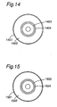
- Fig. 14 is a plan view of another optical disc 1401. With this disc user data is recorded to data area 1402. Information indicative of the method used to adjust the first pulse and last pulse according to the input data signal is recorded to area 1403 at the inside circumference area of the disc using a sequence of pits and lands (marks and spaces). Recording area 1404 at the inside circumference of the disc is used during disc production to record either optimized or typical position information for the first or last mark edge position using a sequence of pits and lands (marks and spaces). Using this disc format, it is possible to determine whether recording is optimized by moving the first and last pulse positions, or by varying the first and last pulse width, by reading area 1403.
- the leading and trailing mark edge positions needed for optimized recording will also differ.
- the optimized or typical values stored to a particular area of the disc during disc production can be used as the initial values used in a test recording operation.
- the number of test patterns recorded and the time required for determining the optimum mark edge positions for data recording can be reduced in this case by starting the optimization operation with the optimum or typical values prerecorded during disc production. This is further described below with reference to Fig. 15.
- Fig. 15 is a plan view of another optical disc 1501.
- This disc format user data is recorded to data area 1502.
- Recording area 1503 at the inside circumference of the disc is used during disc production to record either optimized or typical position information for the first or last mark edge position using a sequence of pits and lands (marks and spaces).
- a test recording area 1504. With this format the information recorded to area 1503 is read first and test recording is then performed in area 1504 to record with greater optimization than is possible if recording is optimized using a single setting.
- Fig. 16 is a plan view of yet another optical disc 1601.
- user data is recorded to data area 1602.
- Information indicative of the method used to adjust the first pulse and last pulse according to the input data signal is recorded to area 1603 at the inside circumference area of the disc using a sequence of pits and lands (marks and spaces).
- Recording area 1604 at the inside circumference of the disc is used during disc production to record either optimized or typical position information for the first or last mark edge position using a sequence of pits and lands (marks and spaces).
- Area 1603 can be read with this disc format to determine whether recording is optimized by moving the first and last pulse positions, or by varying the first and last pulse width.
- test recording area 1605. Between the data area 1602 and area 1604 is a test recording area 1605. With this format areas 1603 and 1604 can be read first and test recording then performed in area 1605 to record with greater optimization than is possible if recording is optimized using a single setting.
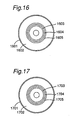
- This optical disc 1701 has a user data area 1702 and an area 1703 at the inside circumference of the disc for recording at the time of disc production either optimized or typical position information (general or default) for the first or last mark edge position using a sequence of pits and lands (marks and spaces).
- Area 1704 is a test recording area.
- Area 1705 is used for recording the optimized leading and trailing mark edge positions determined by the test recording operation, that is, the result of the test recording operation.
- This recorder-specific information typically includes the name of the disc recorder manufacturer, product number, where the disc recorder was manufactured, and the date of manufacture.
- this information can be reproduced when the optical disc 1701 is subsequently loaded into a disc recorder. If the disc recorder is the same as that by which the information was recorded, the optimized leading and trailing mark edge position information can be read directly from disc, and optimized recording reflecting the specific characteristics of that disc recorder can be achieved without requiring another test recording operation.
- this optical disc 1701 when this optical disc 1701 is loaded in a disc recorder for data recording, area 1705 is reproduced to obtain the specifically optimized leading and trailing mark edge position information, and test recording is then performed in area 1704, the number of signal patterns that must be repeatedly recorded to determine the optimum edge positions can be reduced, and the time required for such optimization can be reduced, compared with test recording operations using either a unique edge position setting or the mark and space sequence of optimized or typical leading and trailing mark edge positions prerecorded during disc production.
- Fig. 18 is a plan view of yet another optical disc 1801.
- This optical disc 1801 has a user data area 1802; an area 1803 at the inside circumference of the disc for recording information indicative of the method used to adjust the first pulse and last pulse according to the input data signal using a sequence of pits and lands (marks and spaces); an area 1804 at the inside circumference of the disc for recording at the time of disc production either optimized or typical position information (general) for the first or last mark edge position using a sequence of pits and lands (marks and spaces); a test recording area 1805; and an area 1806 for recording the optimized leading and trailing mark edge positions determined by the test recording operation, that is, the result of the test recording operation.
- area 1803 can be read to determine whether recording is optimized by moving the first and last pulse positions, or by varying the first and last pulse width.
- This recorder-specific information typically includes the name of the disc recorder manufacturer, product number, where the disc recorder was manufactured, and the date of manufacture.
- this information can be reproduced when the optical disc 1801 is subsequently loaded into a disc recorder. If the disc recorder is the same as that by which the information was recorded, the optimized leading and trailing mark edge position information can be read directly from disc, and optimized recording reflecting the specific characteristics of that disc recorder can be achieved without requiring another test recording operation.
- area 1203 in optical disc 1201 shown in Fig. 12 can store information specific to the optical disc 1201, such as the manufacturer's name, product number, date and place of production, disc format, and recording film composition.
- this disc-specific information and the leading and trailing mark edge position information obtained by test recording are stored to memory 130 of the disc recorder.
- this disc-specific information and mark edge position information is read and stored to memory 130.
- Disc-specific information and mark edge position information for various discs, that is, discs from different manufacturers and different versions of a disc, is thus accumulated in memory 130.
- the disc-specific information is read from area 1203 of the loaded disc and used to reference the matching disc-specific information in memory 130 to fetch therefrom the matching specific mark edge position information. This eliminates the need for repeatedly recording signal patterns to determine the optimum position information, or reduces the number of test recording operations required, and in both cases shortens the required optimization time.
- area 1503 in optical disc 1501 shown in Fig. 15 can store information specific to the optical disc 1501, such as the manufacturers name, product number, date and place of production, disc format, and recording film composition. In this case this disc-specific information and the leading and trailing mark edge position information obtained by test recording are stored to memory 130 of the disc recorder.
- the disc-specific information is read from area 1503 of the loaded disc and used to reference the matching disc-specific information in memory 130 to fetch therefrom the matching specific mark edge position information. This eliminates the need for repeatedly recording signal patterns to determine the optimum position information, or reduces the number of test recording operations required, and in both cases shortens the required optimization time.
- area 1603 in optical disc 1601 shown in Fig. 16 can also store the above-noted information specific to the optical disc 1601. In this case this disc-specific information and the leading and trailing mark edge position information obtained by test recording are stored to memory 130 of the disc recorder.
- the disc-specific information is read from area 1603 of the loaded disc and used to reference the matching disc-specific information in memory 130 to fetch therefrom the matching specific mark edge position information. Again, this eliminates the need for repeatedly recording signal patterns to determine the optimum position information, or reduces the number of test recording operations required, and in both cases shortens the required optimization time.
- area 1703 in optical disc 1701 shown in Fig. 17 can also store the above-noted information specific to the optical disc 1701. In this case this disc-specific information and the leading and trailing mark edge position information obtained by test recording are stored to memory 130 of the disc recorder.
- the disc-specific information is read from area 1703 of the loaded disc and used to reference the matching disc-specific information in memory 130 to fetch therefrom the matching specific mark edge position information. Again, this eliminates the need for repeatedly recording signal patterns to determine the optimum position information, or reduces the number of test recording operations required, and in both cases shortens the required optimization time.
- area 1803 in optical disc 1801 shown in Fig. 18 can also store the above-noted information specific to the optical disc 1801. In this case this disc-specific information and the leading and trailing mark edge position information obtained by test recording are stored to memory 130 of the disc recorder.
- the disc-specific information is read from area 1803 of the loaded disc and used to reference the matching disc-specific information in memory 130 to fetch therefrom the matching specific mark edge position information. Again, this eliminates the need for repeatedly recording signal patterns to determine the optimum position information, or reduces the number of test recording operations required, and in both cases shortens the required optimization time.
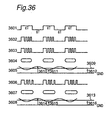
- FIG. 34 and Fig. 35 together show a single disc format table starting from the pit area and mirror area at the inside circumference of the disc at the top of the table in Fig. 34 and proceeding to the recording area continuing from Fig. 34 to the outside circumference of the disc in Fig. 35.
- the pit area comprises an initialization zone and a control data zone on the outside circumference side of the initialization zone.
- the initialization zone at the inside circumference of the disc prevents the servo from going completely off track if the optical head happens to move to the inside circumference side of the target address.
- the control data zone stores disc-specific information such as the disc type, read power level, pulse adjustment method, temporary power and operational power level information, first and last pulse position information, the optical disc manufacturer, lot number, and product number.
- the content of the control data zone is typically recorded a plurality of times to prevent the disc from becoming unreadable as a result of scratches or soiling.
- the mirror area simply links the pit area with the data recording area. None is recorded to the mirror area and no signals are reproduced therefrom. It is therefore easy to detect if the optical head passes over the mirror area, and the optical head can therefore be more accurately positioned to a specific location on the disc.
- the recording area comprises guard track zone 1, disc test zone 1, drive test zone 1, recorder-specific information recording zone 1, disc error management area 1, the data area, disc error management area 2, recorder-specific information recording zone 2, drive test zone 3, disc test zone 2, and guard track zone 2.
- the servo may still be unstable immediately after leaving the mirror zone.
- the guard track zone 1 is therefore blank.
- the disc test zone 1 is used by the disc manufacturer. The power level used for recording and the optimum pulse position information are determined using this disc test zone 1.
- the drive test zone 1 is used by the disc recorder. By separating the disc test zone and drive test zone, the disc manufacturer can record other desirable information to the disc test zone.
- the recorder-specific information recording zone 1 is the area to which data specific to a new disc recorder is recorded each time the disc is loaded into a new disc recorder for recording.
- recorder-specific information 1 - n is read from the recorder-specific information recording zone 1 to determine whether data specific to that disc recorder is already stored in the recorder-specific information recording zone 1.
- the recorder-specific information of the disc recorder to which the optical disc is loaded is also contained in memory 130.
- a CPU (not shown in the figures) controlling the memory 130 can determine whether the same recorder-specific information is already present.
- the recorder-specific information, temporary power and operational power level information, and pulse position information are stored as one data set to the recorder-specific information recording zone 1. From several seconds to ten several seconds may be required to determine the temporary power and operational power level information and pulse position information in this case by means of a test recording operation.
- the temporary power and operational power level information and pulse position information belonging to the recorder-specific information data set identical to the data read from the recorder-specific information recording zone 1 is read from memory.
- This temporary power and operational power level information is then sent to memory 132, and the pulse position information is sent to memory 129. It is to be noted that because this information can be read directly from disc, the several seconds to ten several seconds needed for a test recording operation to determine this information can be saved.
- n sets of recorder-specific information, temporary power and operational power level information, and pulse position information will be recorded to the disc.
- these n data sets are recorded to a plurality of locations on the disc, such as at the inside circumference and outside circumference of the disc.
- the recorder-specific information is read and the disc recorder determines that the optical disc was previously written to by that disc recorder, the content recorded for the test recording operation can be simplified.
- Information unique to a particular combination of disc recorder and optical disc is recorded a plurality of times to prevent problems arising from the data becoming unreadable as a result of scratches or soiling.
- the recorder-specific information recording zone also reserves areas for recording this information by a plurality of disc recorders. This is because there are minute differences in laser power in different disc recorders.
- the disc error management area 1 is reserved for managing disc errors.
- the data area is for recording user data.
- Disc error management area 2 is likewise reserved for managing disc errors.
- the recorder-specific information recording zone 2 stores the same information stored to recorder-specific information recording zone 1, that is, information unique to a particular combination of optical disc and disc recorder by which the optical disc was recorded.
- the drive test zone 2 is used for test recording by the disc recorder in the same manner as drive test zone 1.
- the information can be reproduced from one area when it cannot be reproduced from the other area as a result of disc damage or soiling. If the disc is greatly warped, it is also possible to perform the test recording operation at both inside and outside circumference zones to interpolate the best recording parameters based on a particular radial position.
- the disc test zone 2 is also used for test recording operations by the disc manufacturer in the same manner as disc test zone 1.
- By providing a disc test zone at both the inside circumference and outside circumference sides of a disc it is possible to determine the effect of disc warpage on recording, and use this information as an inspection and shipping standard.
- Guard track zone 2 is also blank and is not used for recording. By providing guard track zone 2 at the outside circumference edge of the disc, it is possible to prevent the servo from going completely off track if the optical head happens to move beyond the target address.
- the above-described disc zones and recording areas are managed using their disc address, which the disc recorder reads and used to determine the disc layout and zone/area locations.
- information specific to the data storage area 201 that is, the disc manufacturer, product number, production date and location, disc format, and recording film type, can also be recorded to the optical disc shown in Fig. 2. It will also be obvious that in this case the disc-specific information as well as the leading and trailing mark edge position information are stored to memory 130 of the disc recorder.
- the disc-specific information is read from the loaded disc and used to reference the matching disc-specific information in memory 130 to fetch therefrom the matching specific mark edge position information. This eliminates the need for repeatedly recording signal patterns to determine the optimum position information, or reduces the number of test recording operations required, and in both cases shortens the required optimization time.
- the optimum leading and trailing mark edge positions are determined by test recording, but this test recording operation can be preceded by an operation for optimizing the output power levels, including both peak power and bias power levels, of the laser beam used for the test recording operation.
- the laser power level thus optimized before mark edge positions are optimized is referred to herein as the "temporary power level.” This is in contrast to the operational power level, which is the laser power level optimized after optimizing the mark edge positions.
- the temporary power level is the power level used to determine the optimum leading and trailing mark edge positions.
- the operational power level is the power level used for actual recording in the data area. Variations in laser power from the optimum emission level cause various problems. These problems are described below.
- the optimum leading and trailing mark edge positions depend on various optical disc characteristics as well as the laser power used for test recording. If laser power changes greatly, the optimum leading and trailing mark edge positions cannot be determined; even if they are determined, recording quality will be poor. The reason for this is described with reference to Fig. 19.
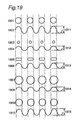
- Fig. 19 shows mark shapes and the resulting reproduction signal when a 3T signal, that is, the shortest mark length signal, is recorded with different laser power levels.
- Marks 1901 result from an optimized laser power setting. Note the mark length and space length are substantially equal. The amplitude 1911 of the resulting reproduction signal 1902 is therefore high.
- Marks 1903 result from a too-low laser power setting. Note that mark length is shorter than the space length. Because mark and space length is not the same, the amplitude 1912 of the resulting reproduction signal 1904 is lower than amplitude 1911.
- Marks 1905 result when the laser is driven at the power level used to produce marks 1903 but the emission time is longer than that producing marks 1903. By thus increasing emission time, mark length and space length are made substantially equal, but the mark width is narrower than that of marks 1901 formed at the optimized laser power setting.
- the amplitude 1913 of the resulting reproduction signal 1906 is therefore lower than amplitude 1911.
- Marks 1907 result from a too-high laser power setting. Note that marks are longer than the spaces. Because mark and space length is not the same, the amplitude 1914 of the resulting reproduction signal 1908 is lower than amplitude 1911.
- Marks 1909 result when the laser is driven at the power level used to produce marks 1907 but the emission time is shorter than that producing marks 1907. By thus decreasing emission time, mark length and space length are more nearly equal, but the high laser power setting prevents formation of equal length marks and spaces.
- the amplitude 1915 of the resulting reproduction signal 1910 is therefore lower than amplitude 1911.
- Switch 121 is conductive through contacts 122 and 124 at this time.
- the power level setting circuit 119 first sets the default peak and bias power levels to the laser drive circuit 109.
- the output signal from unique pattern generator 127a of the recording data generator 127 is then modulated by the modulation circuit 126, and passed through switch 121 to the pulse generator 111 for conversion to a pulse signal.
- This pulse signal is then passed through delay circuit 138 to the pulse moving circuit 110 from which a signal in which the leading and trailing pulse edges are shifted is output.
- Signal patterns output from the modulation circuit 126 are shown in Fig. 20. These signal patterns can be prestored to the optical disc or in the disc recorder.
- Fig. 20 (a) shows the sector format of the optical disc 101, comprising a data storage area 201, writing test zone 202, track 2001, addresses 2002 and 2003, and sectors 2004.
- Each sector 2004 comprises main data 2006 and a VFO signal 2005 for PLL 116 synchronization (see Fig. 1).
- the VFO signal has a simple 4T period.
- the main data 2006 comprises a plurality of frames 2007, 2008, 2009. Each frame comprises a synchronization mark for synchronizing the start of data reproduction, a DSV compensation pattern 2011 for resetting the DSV to 0, and a simple 3T pattern signal 2012. Note that the DSV is the difference of marks and spaces within a specific period in the sync mark. A typical 3T pattern signal 2012 is shown in Fig. 20 (c). Note that by resetting the DSV of the recording signal pattern to 0, the DSV compensation pattern 2011 enables the signal pattern to be correctly digitized during reproduction.
- a 4T or other pattern signal can be used in place of the 3T pattern signal 2012 insofar as the signal has a simple repeating pattern.
- an appropriate laser power setting can be determined even when the optimum leading and trailing mark edge positions are not yet determined and recording quality will therefore be low using a random pattern signal.
- the memory required for data comparator 131 can be reduced by comparing signals before and after modulation.
- the VFO signal will also have a 4T period, thereby preventing asymmetry between the VFO signal part and the main data, and enabling more accurate digitization.
- signals containing a simple 3T pattern are frequently used in this exemplary embodiment
- patterns comprising signal groups contained in a signal type having the same optimum adjustment of leading and trailing mark edge positions cam be alternatively used.
- an appropriate laser power setting can be determined even when the optimum leading and trailing mark edge positions are not yet determined and recording quality will therefore be low using a random pattern signal containing all signal types.
- the output signal from pulse moving circuit 110 is input to the laser drive circuit 109, which drives the semiconductor laser to emit at peak and bias power levels according to this output signal and thereby form a sequence of marks on the disc.
- the data comparator 131 When recording ends the mark sequence is reproduced, and the output signal from demodulation circuit 117 is input to the data comparator 131.
- the output signal from unique pattern generator 127a is also input to data comparator 131.
- the data comparator 131 thus compares the recording data and the reproduced data and detects, for example, a byte error rate (BER).
- BER byte error rate
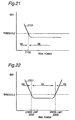
- Fig. 21 shows the relationship between peak power and BER.
- Peak power is on the X axis and BER on the Y axis in Fig. 21. If reproduction conditions are equal, a low BER generally indicates more accurate recording. Bias power is therefore fixed and the peak power varied while this record and reproduce loop is repeated to find the peak power 2102 (typically approximately 8 mW) at which the BER reaches a specific threshold value.
- a predefined margin is then added to this peak power 2102 level to set the peak power level, typically approximately 10 mW. It is to be noted that by appropriately controlling this added margin the peak power level can be optimized for the test recording operation determining the optimum leading and trailing mark edge positions. Note, further, that this margin can be applied to the peak power level obtaining a BER of a particular threshold value by multiplying the peak power level by a margin constant (such as 1.2) or adding thereto a margin constant such as 2 mW.
- a margin constant such as 1.2
- a method for determining bias power is described next.
- the peak power setting determined by the power level setting circuit 119 as described above and the initial bias power setting are first set to the laser drive circuit 109.
- the modulation circuit 126 then outputs a random signal according to the random pattern signal from the random pattern generator 127b of the recording data generator 127, and the pattern is recorded using the above power settings.
- the modulation circuit 126 then generates a signal containing many 3T patterns according to a signal from the unique pattern generator 127a of the recording data generator 127, and this pattern is recorded using the above power settings.
- the data comparator 131 When recording ends the mark sequence is reproduced, and the output signal from demodulation circuit 117 is input to the data comparator 131.
- the output signal from recording data generator 127 is also input to data comparator 131.
- the data comparator 131 thus compares the recording data and the reproduced data and detects, for example, a byte error rate (BER).
- BER byte error rate
- Fig. 22 shows the relationship between bias power and BER.
- Bias power is on the X axis and BER on the Y axis in Fig. 22. If reproduction conditions are equal, a low BER generally indicates more accurate recording. Peak power is therefore fixed and the bias power varied while this record and reproduce loop is repeated to find the low 2202 and high 2203 bias power settings at which the BER reaches a specific threshold value. Note that these low and high bias power settings are typically approximately 3 mW and 7 mW, respectively. The average, 5 mW in this case, between these low and high bias power levels is then used as the bias power level for test recording obtaining the optimum leading and trailing mark edge positions.
- a further method for determining the bias power setting is described next with reference to Fig. 23.
- a signal containing many simple 3T patterns is recorded after recording a random signal and the BER is detected.
- a random signal is then recorded again, a signal containing many simple 11T patterns is recorded, and the BER is detected.
- the high and low bias power levels are then determined for the 3T pattern signal and the 11T pattern signal, and the average of the greater of the two low settings, level 2302 in this case, and the lesser of the two high settings, level 2303 in this case, is obtained and used as the bias power level for test recording obtaining the optimum leading and trailing mark edge positions.
- the bias power level can be more appropriately set by using the average of the ranges in which both are below this threshold value.
- this preferred embodiment of the present invention detects the BER as a means of detecting reproduction signal quality
- the present invention shall not be so limited and various other methods of detecting reproduction signal quality, such as by detecting the jitter, can be alternatively used.
- FIG. 36 Another method of determining the peak power level is described below with reference to Fig. 36.
- This method detects asymmetry using a simple 6T pattern signal. Shown in Fig. 36 are the 6T pattern signal 3601 output from pattern signal generator 125; the output signal 3602 of the pulse generator 111; output signal 3603 from pulse moving circuit 110; and the mark pattern 3604 formed in the track on optical disc 101 by modulating laser output between peak and bias power levels according to signal 3603. It is to be noted that while signals 3601, 3602, and 3603 are not generated on the same time base, for convenience they are shown with corresponding parts in each signal aligned vertically.
- the pattern signal in this case represents marks and spaces with a simple 6T period, and thus contains types 5S5M and 5M5S of the eighteen pattern types shown in Fig. 5 (a).
- the laser is then driven based on drive signal 3603 in Fig. 36 to record the marks 3604.
- pattern signal 3601 in Fig. 36 is repeatedly recorded around one complete circumference of the recording track. When this track is recorded, it is then reproduced.
- Reproduction includes converting an optical signal from the photodetector 108 to an electrical signal, and then processing this electrical signal with preamplifier 112, low pass filter 113, and reproduction equalizer 114.
- the reproduction signal 3605 from the reproduction equalizer 114 is applied to asymmetry measuring circuit 140 and digitizing circuit 115.
- the digitizing circuit 115 adjusts the slice level signal 3609 so that the output level corresponding to a mark and the output level corresponding to a space in the output signal of the digitizing circuit are at equal intervals, and applies this slice level signal 3609 to the asymmetry measuring circuit 140.
- the asymmetry measuring circuit 140 compares the average of the high 3611 and low 3610 peak values of the reproduction signal 3605 with the slice level signal 3609. When the difference or ratio therebetween is outside a specified range, the peak power setting is off. The peak power setting is therefore adjusted according to the sign of this difference or ratio. This 6T pattern signal recording, reproduction, and asymmetry measurement loop is then repeated until the detected asymmetry is within a specific range.
- the temporary power level information used for adjusting the leading and trailing mark edge positions can be recorded. Note that this temporary power level information includes the peak power, bias power, margin constant, and asymmetry information. It is also possible to record all or just part of this temporary power level information. This is also true of the other optical discs described below.
- area 1503 is read to obtain the temporary power level information.
- Test recording is then performed to determine the specific bias power level.
- the ratio between the typical peak and bias power level information read from area 1503 is then obtained. This ratio can then be multiplied with the specific bias power level obtained by test recording to obtain the specific peak power setting.
- the specific bias power level is obtained through test recording to compensate for deterioration of the laser, lens fogging, and other factors causing a loss of laser power.
- Test recording for determining the specific peak power setting can therefore be omitted, and the time required to determine the conditions for optimized recording can be shortened.
- the optimum margin added will vary slightly according to such factors as the recording film composition. For example, if the optimum peak power is the value at 1.2 times the threshold value, a more precise peak power setting can be obtained by recording this optimal margin (that is, 1.2 or the result of a specific operation applied to 1.2) to disc.
- the temporary power level information used for adjusting the leading and trailing mark edge positions can be recorded. Note that this temporary power level information includes the peak power, bias power, margin constant, and asymmetry information.
- area 1604 is read to obtain the temporary power level information.
- Test recording is then performed to determine the specific bias power level.
- the ratio between the typical peak and bias power level information read from area 1604 is then obtained. This ratio can then be multiplied with the specific bias power level obtained by test recording to obtain the specific peak power setting.
- Test recording for determining the 'specific peak power setting can therefore be omitted, and the time required to determine the conditions for optimized recording can be shortened.
- a more precise peak power setting can be obtained by recording this optimal asymmetry value (that is, either 1.05 or the result of a specific operation applied to 1.05) to disc.
- the optimum margin added will vary slightly according to such factors as the recording film composition. For example, if the optimum peak power is the value at 1.2 times the threshold value, a more precise peak power setting can be obtained by recording this optimal margin (that is, 1.2 or the result of a specific operation applied to 1.2) to disc.
- the temporary power level information used for adjusting the leading and trailing mark edge positions can be recorded. Note that this temporary power level information includes the peak power, bias power, margin constant, and asymmetry information.
- area 1703 is read to obtain the temporary power level information.
- Test recording is then performed to determine the specific bias power level.
- the ratio between the typical peak and bias power level information read from area 1703 is then obtained. This ratio can then be multiplied with the specific bias power level obtained by test recording to obtain the specific peak power setting. Test recording for determining the specific peak power setting can therefore be omitted, and the time required to determine the conditions for optimized recording can be shortened.
- a more precise peak power setting can be obtained by recording this optimal asymmetry value (that is, either 1.05 or the result of a specific operation applied to 1.05) to disc.
- the optimum margin added will vary slightly according to such factors as the recording film composition. For example, if the optimum peak power is the value at 1.2 times the threshold value, a more precise peak power setting can be obtained by recording this optimal margin (that is, 1.2 or the result of a specific operation applied to 1.2) to disc.
- the temporary power level information used for adjusting the leading and trailing mark edge positions can be recorded. Note that this temporary power level information includes the specific peak power, specific bias power, margin constant, and asymmetry information.
- area 1705 is read to obtain specific temporary power level information, such as the specific bias power setting. If the specific bias power setting is the same as the typical bias power setting recorded to area 1705, test recording for determining the specific peak power setting and the optimum leading and trailing mark edge positions can therefore be omitted, and the time required to determine the conditions for optimized recording can be shortened.
- the temporary power level information used for adjusting the leading and trailing mark edge positions can be recorded. Note that this temporary power level information includes the peak power, bias power, margin constant, and asymmetry information.
- area 1804 is read to obtain the temporary power level information.
- Test recording is then performed to determine the specific bias power level.
- the ratio between the typical peak and bias power level information read from area 1804 is then obtained. This ratio can then be multiplied with the specific bias power level obtained by test recording to obtain the specific peak power setting. Test recording for determining the specific peak power setting can therefore be omitted, and the time required to determine the conditions for optimized recording can be shortened.
- a more precise peak power setting can be obtained by recording this optimal asymmetry value (that is, either 1.05 or the result of a specific operation applied to 1.05) to disc.
- the optimum margin added will vary slightly according to such factors as the recording film composition. For example, if the optimum peak power is the value at 1.2 times the threshold value, a more precise peak power setting can be obtained by recording this optimal margin (that is, 1.2 or the result of a specific operation applied to 1.2) to disc.
- the temporary power level information used for adjusting the leading and trailing mark edge positions can be recorded. Note that this temporary power level information includes the specific peak power, specific bias power, margin constant, and asymmetry information.
- area 1806 is read to obtain specific temporary power level information, such as the specific bias power setting. If the specific bias power setting is the same as the typical bias power setting recorded to area 1806, test recording for determining the specific peak power setting and adjusting leading and trailing mark edge positions according to the data can therefore be omitted, and the time required to determine the conditions for optimized recording can be shortened.
- this disc-specific information and the temporary power level information (such as peak power, bias power, margin constant, asymmetry information) used for adjusting the leading and trailing mark edge positions can be stored to memory 130 of the disc recorder.
- area 1203 is read to detect whether the disc-specific information is already in memory 130. If it is, test recording is then performed to determine the specific bias power level. The ratio between the typical peak and bias power level information in memory 130 is then obtained. This ratio can then be multiplied with the specific bias power level obtained by test recording to obtain the specific peak power setting. Test recording for determining the specific peak power setting can therefore be omitted, and the time required to determine the conditions for optimized recording can be shortened.
- this disc-specific information and the temporary power level information (such as peak power, bias power, margin constant, asymmetry information) used for adjusting the leading and trailing mark edge positions can be stored to memory 130 of the disc recorder.
- area 1503 is read to detect whether the disc-specific information is already in memory 130. If it is, test recording is then performed to determine the specific bias power level. The ratio between the typical peak and bias power level information in memory 130 is then obtained. This ratio can then be multiplied with the specific bias power level obtained by test recording to obtain the specific peak power setting. Test recording for determining the specific peak power setting can therefore be omitted, and the time required to determine the conditions for optimized recording can be shortened.
- the margin constant, asymmetry information, or other temporary power level information cannot be read from area 1503 because of a disc error or soiling, the optimum temporary power level can still be quickly obtained because this unreadable information is in memory 130.
- this disc-specific information and the temporary power level information (such as peak power, bias power, margin constant, asymmetry information) used for adjusting the leading and trailing mark edge positions can be stored to memory 130 of the disc recorder.
- area 1603 is read to detect whether the disc-specific information is already in memory 130. If it is, test recording is then performed to determine the specific bias power level. The ratio between the typical peak and bias power level information in memory 130 is then obtained. This ratio can then be multiplied with the specific bias power level obtained by test recording to obtain the specific peak power setting. Test recording for determining the specific peak power setting can therefore be omitted, and the time required to determine the conditions for optimized recording can be shortened.
- the margin constant, asymmetry information, or other temporary power level information cannot be read from area 1603 because of a disc error or soiling, the optimum temporary power level can still be quickly obtained because this unreadable information is in memory 130.
- this disc-specific information and the temporary power level information (such as peak power, bias power, margin constant, asymmetry information) used for adjusting the leading and trailing mark edge positions can be stored to memory 130 of the disc recorder.
- area 1703 is read to detect whether the disc-specific information is already in memory 130. If it is, test recording is then performed to determine the specific bias power level. The ratio between the typical peak and bias power level information in memory 130 is then obtained. This ratio can then be multiplied with the specific bias power level obtained by test recording to obtain the specific peak power setting. Test recording for determining the specific peak power setting can therefore be omitted, and the time required to determine the conditions for optimized recording can be shortened.
- margin constant, asymmetry information, or other temporary power level information cannot be read from area 1703 or 1705 because of a disc error or soiling, the optimum temporary power level can still be quickly obtained because this unreadable information is in memory 130.
- the optimum temporary power level setting can be obtained quickly by reading the information from memory 130.
- this disc-specific information and the temporary power level information (such as peak power, bias power, margin constant, asymmetry information) used for adjusting the leading and trailing mark edge positions can be stored to memory 130 of the disc recorder.
- area 1803 is read to detect whether the disc-specific information is already in memory 130. If it is, test recording is then performed to determine the specific bias power level. The ratio between the typical peak and bias power level information in memory 130 is then obtained. This ratio can then be multiplied with the specific bias power level obtained by test recording to obtain the specific peak power setting. Test recording for determining the specific peak power setting can therefore be omitted, and the time required to determine the conditions for optimized recording can be shortened.
- margin constant, asymmetry information, or other temporary power level information cannot be read from area 1803 or 1805 because of a disc error or soiling, the optimum temporary power level can still be quickly obtained because this unreadable information is in memory 130.
- the optimum temporary power level setting can be obtained quickly by reading the information from memory 130.
- the optimum leading and trailing mark edge positions are determined by test recording to a specific area as described above. It is alternatively possible, however, to determine the above specific bias and peak power settings, and then determine the operational power level setting for the laser beam used for data recording.
- the margin used to determine the peak power may be low.
- the disc can normally be recorded properly even when the effective temporary power level drops 2 mW if the disc area to be written is soiled, it may not be possible to record correctly when there is only a 1 mW drop if the margin is too low.
- switch 121 is conductive through contacts 122 and 124.
- the power level setting circuit 119 first sets the default peak and bias power levels to the laser drive circuit 109 based on data read from memory 132.
- the output signal from random pattern generator 127b of the recording data generator 127 is then modulated by the modulation circuit 126, and passed through switch 121 to the pulse generator 111 for conversion to a pulse signal.
- This pulse signal is then passed to the pulse moving circuit 110 from which a signal in which the leading and trailing pulse edges are shifted is output.
- the signal output from modulation circuit 126 is a random signal in which the DSV is 0.
- the output signal from pulse moving circuit 110 is input to the laser drive circuit 109, which drives the semiconductor laser to emit at peak and bias power levels according to this output signal and thereby form a sequence of marks on the disc.
- the data comparator 131 When recording ends the mark sequence is reproduced, and the output signal from demodulation circuit 117 is input to the data comparator 131.
- the output signal from random pattern generator 127b is also input to data comparator 131.
- the data comparator 131 thus compares the recording data and the reproduced data and detects, for example, a byte error rate (BER).
- BER byte error rate
- Fig. 24 shows the relationship between peak power and BER. Peak power is on the X axis and BER on the Y axis in Fig. 24. If reproduction conditions are equal, a low BER generally indicates more accurate recording. Bias power is therefore fixed and the peak power varied while this record and reproduce loop is repeated to find the peak power 2402 (typically approximately 8 mW) at which the BER reaches a specific threshold value. A predefined margin is then added to this peak power 2402 level to set the peak power level, typically approximately 10 mW. It is to be noted that by appropriately controlling this added margin the peak power level can be optimized for data recording. Note, further, that this margin can be applied to the peak power level obtaining a BER of a particular threshold value by multiplying the peak power level by a constant factor (such as 1.2) or adding thereto a constant such as 2 mW.
- a constant factor such as 1.2
- a method for determining bias power is described next.
- the peak power setting determined by the power level setting circuit 119 as described above and the initial bias power setting are first set to the laser drive circuit 109.
- the modulation circuit 126 then outputs a random signal according to the random pattern signal from the random pattern generator 127b, and the pattern is recorded using the above power settings.
- the data comparator 131 When recording ends the mark sequence is reproduced, and the output signal from demodulation circuit 117 is input to the data comparator 131.
- the output signal from random pattern generator 127b is also input to data comparator 131.
- the data comparator 131 thus compares the recording data and the reproduced data and detects, for example, a byte error rate (BER).
- BER byte error rate
- Fig. 25 shows the relationship between bias power and BER.
- Bias power is on the X axis and BER on the Y axis in Fig. 25. If reproduction conditions are equal, a low BER generally indicates more accurate recording. Peak power is therefore fixed and the bias power varied while this record and reproduce loop is repeated to find the low 2502 and high 2503 bias power settings at which the BER reaches a specific threshold value. Note that these low and high bias power settings are typically approximately 3 mW and 7 mW, respectively. The average, 5 mW in this case, between these low and high bias power levels is then used as the bias power level for test recording obtaining the optimum leading and trailing mark edge positions.
- this preferred embodiment of the present invention detects the BER as a means of detecting reproduction signal quality
- the present invention shall not be so limited and various other methods of detecting reproduction signal quality,'such as by detecting the jitter, can be alternatively used.
- the operational power level information can be recorded. Note that this operational power level information includes the peak power, bias power, and margin constant. It is also possible to record all or just part of this operational power level information. This is also true of the other optical discs described below.
- area 1503 is read to obtain the operational power level information.
- Test recording is then performed to determine the specific bias power level.
- the ratio between the typical peak and bias power level information read from area 1503 is then obtained. This ratio can then be multiplied with the specific bias power level obtained by test recording to obtain the optimum specific peak power setting.
- Test recording for determining the specific peak power setting can therefore be omitted, and the time required to determine the conditions for optimized recording can be shortened.
- the optimum margin added will vary slightly according to such factors as the recording film composition. For example, if the optimum peak power is the value at 1.2 times the threshold value, a more precise peak power setting can be obtained by recording this optimal margin (that is, 1.2 or the result of a specific operation applied to 1.2) to disc.
- the temporary power level information can be used.
- the operational power level information can be used to obtain the temporary power level.
- the operational power level information can likewise be recorded to area 1604 of the optical disc 1601 shown in Fig. 16 in addition to the optimum or typical leading and trailing mark edge positions recorded during manufacture.
- area 1604 is read to obtain the operational power level information.
- the ratio between the typical peak and bias power level information read from area 1604 is then obtained. After the specific peak power is determined, this ratio can be multiplied with the specific peak power to predict the optimum specific bias power setting. Test recording for determining the specific bias power setting can therefore be omitted, and the time required to determine the conditions for optimized recording can be shortened.
- the optimum bias power setting before edge position adjustment can be predicted by determining the power level information after edge position adjustment. For example, to determine the bias power setting before edge position adjustment, the pre-adjustment peak power setting is determined, the ratio between the peak power and bias power determined after such adjustment and recorded to area 1604 is calculated, and this ratio is then applied to the pre-adjustment peak power setting to predict the optimum bias power setting before edge position adjustment.
- the operational power level information can likewise be recorded to area 1703 of the optical disc 1701 shown in Fig. 17 in addition to the optimum or typical leading and trailing mark edge positions recorded during manufacture.
- the operational power level information can be used. First, the operational power setting recorded to area 1703 is read. The bias power setting of the temporary power level information is then obtained by test recording, and the ratio between the peak and bias power settings of the operational power level setting is calculated. The optimum peak power level of the temporary power level information can then be calculated by multiplying this ratio with the bias power setting of the temporary power level information. Test recording for determining the specific peak power setting of the temporary power level can therefore be omitted, and the time required to determine the conditions for optimized recording can be shortened.
- the operational power level information can likewise be recorded to area 1705 of the optical disc 1701 shown in Fig. 17 in addition to the leading and trailing mark edge positions determined by test recording.
- area 1705 is read to obtain the temporary power level information. If the bias power setting determined through test recording is the same as the bias power setting recorded to area 1705, subsequent test recording for determining the specific peak power setting can be omitted, and the time required to determine the conditions for optimized recording can be shortened.
- the operational power level information can likewise be recorded to area 1804 of the optical disc 1801 shown in Fig. 18 in addition to the optimum or typical leading and trailing mark edge positions recorded during manufacture.
- the operational power level information can be used.
- the operational power setting recorded to area 1804 is read.
- the bias power setting of the temporary power level information is then obtained by test recording, and the ratio between the peak and bias power settings of the operational power level setting is calculated.
- the optimum peak power level of the temporary power level information can then be calculated by multiplying this ratio with the bias power setting of the temporary power level information. Test recording for determining the specific peak power setting of the temporary power level can therefore be omitted, and the time required to determine the conditions for optimized recording can be shortened.
- the operational power level information can likewise be recorded to area 1806 of the optical disc 1801 shown in Fig. 18 in addition to the leading and trailing mark edge positions determined by test recording.
- area 1806 is read to obtain the temporary power level information. If the bias power setting determined through test recording is the same as the bias power setting recorded to area 1806, subsequent test recording for determining the specific peak power setting can be omitted, and the time required to determine the conditions for optimized recording can be shortened.
- this disc-specific information and the operational power level information (such as peak power, bias power, margin constant) used for adjusting the leading and trailing mark edge positions can be stored to memory 130 of the disc recorder.
- area 1203 is read to detect whether the disc-specific information is already in memory 130. If it is, test recording is then performed to determine the specific bias power level. The ratio between the peak and bias power level information in memory 130 is then obtained. This ratio can then be multiplied with the specific bias power level obtained by test recording to obtain the specific peak power setting. Test recording for determining the specific peak power setting can therefore be omitted, and the time required to determine the conditions for optimized recording can be shortened.
- the operational power level information can be used. First, the operational power setting recorded to area 1203 is read. The bias power setting of the temporary power level information is then obtained by test recording, and the ratio between the peak and bias power settings of the operational power level setting is calculated. The optimum peak power level of the temporary power level information can then be calculated by multiplying this ratio with the bias power setting of the temporary power level information. Test recording for determining the specific peak power setting of the temporary power level can therefore be omitted, and the time required to determine the conditions for optimized recording can be shortened.
- this disc-specific information and the operational power level information (such as peak power, bias power, margin constant) used for adjusting the leading and trailing mark edge positions can be stored to memory 130 of the disc recorder.
- area 1603 is read to detect whether the disc-specific information is already in memory 130. If it is, test recording is then performed to determine the specific bias power level. The ratio between the peak and bias power level information in memory 130 is then obtained. This ratio can then be multiplied with the specific bias power level obtained by test recording to obtain the specific peak power setting. Test recording for determining the specific peak power setting can therefore be omitted, and the time required to determine the conditions for optimized recording can be shortened.
- the operational power level information can be used. First, the operational power setting recorded to area 1603 is read. The bias power setting of the temporary power level information is then obtained by test recording, and the ratio between the peak and bias power settings of the operational power level setting is calculated. The optimum peak power level of the temporary power level information can then be calculated by multiplying this ratio with the bias power setting of the temporary power level information. Test recording for determining the specific peak power setting of the temporary power level can therefore be omitted, and the time required to determine the conditions for optimized recording can be shortened.
- this disc-specific information and the operational power level information (such as peak power, bias power, margin constant) used for adjusting the leading and trailing mark edge positions can be stored to memory 130 of the disc recorder.
- area 1803 is read to detect whether the disc-specific information is already in memory 130. If it is, test recording is then performed to determine the specific bias power level. The ratio between the peak and bias power level information in memory 130 is then obtained. This ratio can then be multiplied with the specific bias power level obtained by test recording to obtain the specific peak power setting. Test recording for determining the specific peak power setting can therefore be omitted, and the time required to determine the conditions for optimized recording can be shortened.
- the operational power level information can be used. First, the operational power setting recorded to area 1803 is read. The bias power setting of the temporary power level information is then obtained by test recording, and the ratio between the peak and bias power settings of the operational power level setting is calculated. The optimum peak power level of the temporary power level information can then be calculated by multiplying this ratio with the bias power setting of the temporary power level information. Test recording for determining the specific peak power setting of the temporary power level can therefore be omitted, and the time required to determine the conditions for optimized recording can be shortened.
- Fig. 26 shows the group delay frequency characteristic of the reproduction system in an actual disc recorder. Although a flat group delay to signal frequency characteristic is the ideal, a group delay characteristic 2601 that is not flat as shown in Fig. 26 is also possible. When the frequency characteristic of the group delay characteristic is not constant, edge shifting may occur in signals with mark and space combinations of various lengths. If the first drive pulse position Tu and last drive pulse position Td are determined in a disc recorder subject to edge shifting, this edge shift component will be included in Tu and Td. While this is not particularly a problem when the disc is then reproduced on the same disc recorder, reproduction performance will be degraded as a result of edge shifting when the disc is read on a disc recorder with a flat group delay characteristic.
- Fig. 27 shows the read signal generated by a disc recorder having a group delay characteristic that is not flat. While the signal represented in Fig. 27 is a simple pattern signal with particularly long marks and spaces, a disc recorder having a non-flat group delay characteristic produces a read signal that has a slope even in space components where the signal should be flat regardless of the shape of the mark. The flatness of the group delay characteristic can be detected by detecting this slope.
- Fig. 28 (a) shows an exemplary method of detecting signal flatness using a test signal comprising long spaces.
- This signal is preferably an embossed pit sequence formed at the inside circumference of the recording medium, but can be, for example, a signal with a constant 14T space period used as a frame synchronization signal, a signal prerecorded to a specific area of the disc, or a signal recorded by the disc recorder.
- the test signal contain long spaces of, for example, 7T to 14T.
- Line 2801 in Fig. 28 indicates the slice level of the digitizing circuit
- curve 2802 is the read signal of a 14T space test signal recorded to and then reproduced from the disc.
- Signal 2802 is sampled at times t0 to t14 based on a PLL clock, obtaining samples s1 to s13.
- Fig. 28 (b) shows a sampling operator 2803 for processing samples s1 to s13 to obtain a sample value. More specifically, the sampling operator 2803 adds samples s1 to s6, and s8 to s13, and then obtains the difference between the two sums. If the signal 2802 has a wave form as shown in Fig. 28, the output from sampling operator 2803 will be a negative value; if the wave slope is the reverse of that shown in Fig. 28, the result will be positive.
- Fig. 29 (a) and (b) show a group delay compensation circuit for a group delay with a specific frequency characteristic.
- Fig. 29 (a) shows an op-amplifier circuit; capacitor 2901 is inserted through resistor 2902 to apply a specific frequency characteristic to the feedback resistance of a normal inverting op-amplifier 2903.
- a desirable group delay characteristic in which the high frequency side is delayed can be achieved by appropriately setting the resistance of resistor 2902 and the capacitance of capacitor 2901. If it is desirable to delay the low frequency side, capacitor 2901 can be replaced by an inductor.
- Fig. 29 (b) is a block diagram of an exemplary group delay compensation circuit.
- the read signal is delayed by delays 2904 and 2905.
- the original signal, the signal delayed by delay 2904, and the signal delayed by delay 2905 are respectively weighted by weighting coefficients 2906, 2907, and 2908, and the weighted signals are then added by adder 2909.
- Signal 2802 is the signal shown in Fig. 28 (a).
- Detector 2803 is the operator shown in Fig. 28 (b), for example.
- Controller 2910 outputs a coefficient based on the output value from the detector 2803 to control the amplification rate of amplifiers 2906, 2907, and 2908. After amplification, that is, weighting, by amplifiers 2906, 2907, and 2908, the signals are added by adder 2909, thereby assuring a flat group delay characteristic for the signal reproduction system, including the group delay compensation circuit.
- the group delay characteristic of the entire reproduction system can also be made flat by detecting the flatness of the space component shown in Fig. 28 (a) and controlling the group delay compensation shown in Fig. 29 (a) and (b) and inserted somewhere in the reproduction system. By then determining Tu and Td, edge shifting when the disc is reproduced by another disc recorder can be minimized, and greater compatibility can be achieved for reproducing the disc in different disc recorders.
- Fig. 30 shows the jitter in the read signal when the group delay compensation of the circuit shown in Fig. 29 is changed. It is to be noted that this read signal is preferably obtained from a pit sequence formed at the inside circumference of the recording medium. However, it can alternatively be a signal recorded to a specific area of the recording medium by the disc recorder in which Tu and Td are set to prevent edge shifting.
- Curve 3001 results from a reproduction system with a flat group delay characteristic; curve 3002 when the group delay characteristic is not flat. As noted above, edge shifting occurs when the group delay characteristic of the entire reproduction system is not flat. This degrades the read performance, and leads to a higher error rate and jitter. If the group delay characteristic is flat, the error rate and jitter are least as shown by curve 3001 when there is no group delay compensation applied by the compensation circuit, but jitter increases as group delay compensation increases.
- the disc recorder has a specific group delay characteristic in its reproduction system, jitter will be least when a certain group delay compensation is applied. Because there is the least edge shifting when compensation is applied to minimize jitter, it can also be concluded that the group delay characteristic is substantially flat. It is therefore possible to minimize edge shifting when a disc recorded on one machine is reproduced on another, and thus assure the greatest read compatibility, by controlling the group delay compensation so as to minimize jitter as shown in Fig. 29 while detecting jitter in a feedback loop, and then determine Tu and Td. It will also be obvious to one with ordinary skill in the related art that the invention shall not be limited to detecting jitter in this feedback loop, and the error rate or other characteristic that varies with the group delay characteristic and edge shifting can be alternatively used.
- the specific group delay characteristic of the disc recorder does not change over time, the same effect can be achieved by compensating for the group delay characteristic in the signal process. Furthermore, if the group delay characteristic is not device-dependent and has a specific characteristic, the same effect can be achieved by compensating for the group delay characteristic using a typical compensation value.
- a recording method for information according to the present invention can compensate at the time data is recorded for the effects of thermal accumulation and thermal interference during recording, and thereby record data with little jitter, by determining before data recording the position of the leading edge of each mark based on the length of the mark to be recorded and the length of the preceding space, and determining the position of the trailing edge of each mark based on the length of the mark to be recorded and the length of the following space.
Claims (5)
- Support d'enregistrement de données comportant une pluralité de pistes concentriques ou en spirale destinées à enregistrer les informations représentées sous forme de marques et d'espaces entre les marques, les marques étant formées en émettant sur une surface d'enregistrement de piste un faisceau optique modulé par une pluralité d'impulsions d'attaque, où le nombre des impulsions d'attaque est ajusté conformément à une longueur d'une partie de marque du signal d'origine devant être enregistré sur la piste, ledit support d'enregistrement de données comprenant :une région de données de commande mémorisant des données de commande formées par des microcuvettes, lesdites données de commande comprenant :au moins l'un d'un déplacement de première impulsion (TF) destiné à modifier une première impulsion desdites impulsions d'attaque, et d'un déplacement de dernière impulsion (TL) destiné à modifier une dernière impulsion desdites impulsions d'attaque, dans lequel lesdits déplacement de première impulsion (TF) et déplacement de dernière impulsion (TL) indiquent soit une valeur de décalage d'impulsion destinée à décaler desdites première et dernière impulsions, respectivement, soit une valeur de largeur d'impulsion destinée à modifier la largeur d'impulsion desdites première et dernière impulsions, respectivement, etun code indiquant un procédé d'utilisation desdits déplacement de première impulsion (TF) et déplacement de dernière impulsion (TL) soit en tant que valeur de décalage d'impulsion, soit en tant que valeur de largeur d'impulsion, etune zone d'enregistrement de données destinée à enregistrer des données, ladite zone d'enregistrement de données comprenant une région d'enregistrement d'informations spécifiques prévue pour l'enregistrement d'informations spécifiques à un dispositif qui sont spécifiques au dispositif d'enregistrement dans lequel le support d'enregistrement de données est chargé.
- Support d'enregistrement de données selon la revendication 1, dans lequel ladite région d'enregistrement d'informations spécifiques est prévue à une pluralité d'emplacements dans ladite zone d'enregistrement de données.
- Support d'enregistrement de données selon la revendication 1, dans lequel lesdites données de commande comprennent en outre des informations temporaires de puissance indicatives d'un niveau de puissance d'un faisceau optique utilisé pour déterminer au moins l'un d'un déplacement de première impulsion spécifique TF et d'un déplacement de dernière impulsion spécifique TL, lesdites informations temporaires de puissance comprenant au moins un élément parmi les suivants : un réglage de puissance de crête, un réglage de puissance de polarisation, une constante de marge, et une asymétrie.
- Support d'enregistrement de données selon la revendication 1, dans lequel lesdites données de commande comprennent en outre des informations de puissance opérationnelle indicatives d'un niveau de puissance d'un faisceau optique utilisé pour l'enregistrement réel des données dans la zone d'enregistrement de données, lesdites informations de puissance opérationnelle comprenant au moins un élément parmi les suivants : un réglage de puissance de crête, un réglage de puissance de polarisation, et une constante de marge.
- Support d'enregistrement de données selon la revendication 1, dans lequel lesdites données de commande comprennent en outre des informations d'asymétrie destinées à être utilisées lors de la détermination de la position desdites impulsions.
Applications Claiming Priority (5)
| Application Number | Priority Date | Filing Date | Title |
|---|---|---|---|
| JP25990898 | 1998-09-14 | ||
| JP25990898 | 1998-09-14 | ||
| JP35010098 | 1998-12-09 | ||
| JP35010098 | 1998-12-09 | ||
| EP99118163A EP0984441B1 (fr) | 1998-09-14 | 1999-09-13 | Support d'enregistrement |
Related Parent Applications (1)
| Application Number | Title | Priority Date | Filing Date |
|---|---|---|---|
| EP99118163A Division EP0984441B1 (fr) | 1998-09-14 | 1999-09-13 | Support d'enregistrement |
Publications (2)
| Publication Number | Publication Date |
|---|---|
| EP0987697A1 EP0987697A1 (fr) | 2000-03-22 |
| EP0987697B1 true EP0987697B1 (fr) | 2000-11-08 |
Family
ID=26544350
Family Applications (9)
| Application Number | Title | Priority Date | Filing Date |
|---|---|---|---|
| EP99115618A Expired - Lifetime EP0987693B1 (fr) | 1998-09-14 | 1999-07-06 | Appareil d'enregistrement optique de données, et support d'enregistrement de données |
| EP99115622A Expired - Lifetime EP0987696B1 (fr) | 1998-09-14 | 1999-07-06 | Procédé d'enregistrement optique de données, et appareil d'enregistrement de données |
| EP99115619A Expired - Lifetime EP0986054B1 (fr) | 1998-09-14 | 1999-07-06 | appareil d'enregistrement optique de données, et support d'enregistrement de données |
| EP99113060A Expired - Lifetime EP0987692B1 (fr) | 1998-09-14 | 1999-07-06 | Appareil d'enregistrement optique de données, et support d'enregistrement de données |
| EP99115620A Expired - Lifetime EP0987694B1 (fr) | 1998-09-14 | 1999-07-06 | Appareil d'enregistrement optique de données, et support d'enregistrement de données |
| EP99115621A Expired - Lifetime EP0987695B1 (fr) | 1998-09-14 | 1999-07-06 | Procédé d'enregistrement optique de données, et support d'enregistrement de données |
| EP99121452A Expired - Lifetime EP0987697B1 (fr) | 1998-09-14 | 1999-09-13 | Support d'enregistrement |
| EP99118163A Expired - Lifetime EP0984441B1 (fr) | 1998-09-14 | 1999-09-13 | Support d'enregistrement |
| EP99121662A Expired - Lifetime EP0987698B1 (fr) | 1998-09-14 | 1999-09-13 | Support d'enregistrement |
Family Applications Before (6)
| Application Number | Title | Priority Date | Filing Date |
|---|---|---|---|
| EP99115618A Expired - Lifetime EP0987693B1 (fr) | 1998-09-14 | 1999-07-06 | Appareil d'enregistrement optique de données, et support d'enregistrement de données |
| EP99115622A Expired - Lifetime EP0987696B1 (fr) | 1998-09-14 | 1999-07-06 | Procédé d'enregistrement optique de données, et appareil d'enregistrement de données |
| EP99115619A Expired - Lifetime EP0986054B1 (fr) | 1998-09-14 | 1999-07-06 | appareil d'enregistrement optique de données, et support d'enregistrement de données |
| EP99113060A Expired - Lifetime EP0987692B1 (fr) | 1998-09-14 | 1999-07-06 | Appareil d'enregistrement optique de données, et support d'enregistrement de données |
| EP99115620A Expired - Lifetime EP0987694B1 (fr) | 1998-09-14 | 1999-07-06 | Appareil d'enregistrement optique de données, et support d'enregistrement de données |
| EP99115621A Expired - Lifetime EP0987695B1 (fr) | 1998-09-14 | 1999-07-06 | Procédé d'enregistrement optique de données, et support d'enregistrement de données |
Family Applications After (2)
| Application Number | Title | Priority Date | Filing Date |
|---|---|---|---|
| EP99118163A Expired - Lifetime EP0984441B1 (fr) | 1998-09-14 | 1999-09-13 | Support d'enregistrement |
| EP99121662A Expired - Lifetime EP0987698B1 (fr) | 1998-09-14 | 1999-09-13 | Support d'enregistrement |
Country Status (13)
| Country | Link |
|---|---|
| US (14) | US6188656B1 (fr) |
| EP (9) | EP0987693B1 (fr) |
| JP (18) | JP3076033B1 (fr) |
| KR (3) | KR100390274B1 (fr) |
| CN (4) | CN1149555C (fr) |
| AU (1) | AU759949B2 (fr) |
| BR (1) | BR9913703A (fr) |
| CA (1) | CA2340352C (fr) |
| DE (9) | DE69900041T2 (fr) |
| ID (1) | ID27793A (fr) |
| MY (1) | MY129811A (fr) |
| TW (1) | TW452781B (fr) |
| WO (2) | WO2000016322A1 (fr) |
Families Citing this family (124)
| Publication number | Priority date | Publication date | Assignee | Title |
|---|---|---|---|---|
| CN1178211C (zh) | 1996-12-20 | 2004-12-01 | 松下电器产业株式会社 | 光记录方法和光记录装置 |
| US7158461B1 (en) * | 1997-12-30 | 2007-01-02 | Samsung Electronics Co., Ltd. | Adaptive writing method for high-density optical recording apparatus and circuit thereof |
| US7391698B2 (en) | 1998-07-23 | 2008-06-24 | Samsung Electronics Co., Ltd. | Adaptive writing method for high-density optical recording apparatus and circuit thereof |
| JP3076033B1 (ja) | 1998-09-14 | 2000-08-14 | 松下電器産業株式会社 | 光学情報の記録再生装置および情報記録媒体 |
| KR100288783B1 (ko) * | 1998-09-18 | 2001-05-02 | 구자홍 | 광기록매체의 기록 광파워 검출저장 및 이를 이용한 기록 광파워 조절장치와 그 방법 |
| US6650607B1 (en) * | 1998-10-12 | 2003-11-18 | Hitachi, Ltd. | Information recording method, information recording medium, and information recording apparatus |
| AU3192000A (en) | 1999-03-19 | 2000-10-09 | Matsushita Electric Industrial Co., Ltd. | Method for optically recording information and device for optically recording information by the same |
| EP1049095A3 (fr) * | 1999-04-28 | 2006-06-28 | Victor Company Of Japan, Ltd. | Support d'enregistrement d'information et appareil de reproduction |
| DE60021960T2 (de) * | 1999-06-25 | 2006-03-23 | Samsung Electronics Co., Ltd., Suwon | Verfahren zur Kompensation von Neigung und/oder Defokussierung, und Vorrichtung für dasselbige |
| US6967911B1 (en) * | 1999-07-12 | 2005-11-22 | Matsushita Electric Industrial Co., Ltd. | Multivalued information recording method, multivalued information recording apparatus, and recording medium |
| US7272094B2 (en) * | 1999-07-15 | 2007-09-18 | Koninklike Philips Electronics N.V. | Methods and devices for recording marks in an information layer of an optical record carrier, and record carriers for use therein |
| KR100326338B1 (ko) | 1999-09-18 | 2002-03-08 | 구자홍 | 광기록매체의 최적 기록방법 |
| JP2001101660A (ja) * | 1999-09-27 | 2001-04-13 | Ricoh Co Ltd | 光記録媒体及び光記録媒体の記録方法 |
| JP3836313B2 (ja) * | 1999-11-15 | 2006-10-25 | シャープ株式会社 | 光記録方法及び光記録装置 |
| JP2001209940A (ja) * | 1999-11-16 | 2001-08-03 | Victor Co Of Japan Ltd | 光ディスク記録再生装置、光ディスク記録再生方法および光ディスク |
| US6807134B2 (en) * | 1999-12-28 | 2004-10-19 | Matsushita Electric Industrial Co., Ltd. | Asymmetry detection apparatus, jitter detection apparatus, and recording/reproduction apparatus |
| JP3839213B2 (ja) * | 2000-02-08 | 2006-11-01 | 株式会社リコー | 相変化型光記録媒体の記録方法および記録再生装置 |
| CA2366576A1 (fr) * | 2000-02-10 | 2001-08-16 | Sony Corporation | Procede d'enregistrement et/ou reproduction de donnees sur/a partir support enregistrement/enregistre, dispositif de reproduction, support enregistrement, procede de reconnaissance d'un support enregistrement/enregistre, et procede enregistrement et/ou de reproduction associe |
| JP3839635B2 (ja) | 2000-03-03 | 2006-11-01 | 株式会社リコー | 光情報記録方法、光情報記録装置及び光情報記録媒体 |
| JP2001283443A (ja) * | 2000-03-31 | 2001-10-12 | Sony Corp | 光記録媒体、光記録方法、光再生方法、および光記録再生装置 |
| US6631108B1 (en) * | 2000-04-03 | 2003-10-07 | Hewlett-Packard Development Company, L.P. | Method for accurate positioning of data marks and spaces on an optical disc |
| WO2001078072A1 (fr) * | 2000-04-07 | 2001-10-18 | Matsushita Electric Industrial Co., Ltd. | Procede d'enregistrement/reproduction de donnees sur/depuis un disque optique |
| US6456751B1 (en) * | 2000-04-13 | 2002-09-24 | Calient Networks, Inc. | Feedback stabilization of a loss optimized switch |
| JP2001297523A (ja) * | 2000-04-14 | 2001-10-26 | Sony Corp | 光ディスク装置 |
| CN1386277A (zh) * | 2000-06-27 | 2002-12-18 | 索尼株式会社 | 数据记录方法、数据记录设备及记录介质 |
| US6636467B1 (en) * | 2000-06-30 | 2003-10-21 | Hewlett-Packard Development Company, L.P. | Method and apparatus for accurately calibrating the timing of a write onto storage media |
| WO2002023542A1 (fr) * | 2000-09-13 | 2002-03-21 | Matsushita Electric Industrial Co., Ltd. | Procede, support et dispositif d'enregistrement d'informations optiques |
| EP1926094A1 (fr) * | 2000-10-05 | 2008-05-28 | Matsushita Electric Industrial Co., Ltd. | Support d'enregistrement optique, procédé d'enregistrement sur support d'enregistrement optique et appareil d'enregistrement sur support d'enregistrement optique |
| KR100403614B1 (ko) * | 2000-11-29 | 2003-11-01 | 삼성전자주식회사 | 고밀도 광기록을 위한 적응적 기록 제어 방법 |
| NL1016751C2 (nl) * | 2000-11-30 | 2002-05-31 | Otb Group Bv | Werkwijze voor het vervaardigen van een schijf met behulp waarvan ten minste een optische registratiedrager wordt gefabriceerd alsmede inrichting geschikt voor het uitvoeren van een dergelijke werkwijze en een schijf vervaardigd met behulp van een dergelijke werkwijze of inrichting. |
| CA2327908A1 (fr) * | 2000-12-08 | 2002-06-08 | Nortel Networks Limited | Appareil et methode permettant de detecter la disparite de bits dans un flux de donnees |
| CN100423092C (zh) * | 2001-02-05 | 2008-10-01 | 雅马哈株式会社 | 调节记录速度和激光功率的光盘装置 |
| CN1252687C (zh) * | 2001-02-05 | 2006-04-19 | 雅马哈株式会社 | 调节记录速度和激光功率的光盘装置 |
| US7095696B2 (en) | 2001-04-09 | 2006-08-22 | Matsushita Electric Industrial Co., Ltd. | Recording/reproducing device |
| JP4351813B2 (ja) * | 2001-04-20 | 2009-10-28 | 株式会社東芝 | 光ディスク装置 |
| US6925041B2 (en) | 2001-05-11 | 2005-08-02 | Matsushita Electric Industrial Co., Ltd. | Information recording apparatus using a mark edge recording |
| US6802705B2 (en) * | 2001-09-10 | 2004-10-12 | Husky Injection Molding Systems Ltd. | Post mold cooling assembly for molded article neck finishes |
| JP4560251B2 (ja) | 2001-09-10 | 2010-10-13 | パイオニア株式会社 | 情報記録装置および情報記録方法 |
| US7376064B2 (en) * | 2002-02-25 | 2008-05-20 | Samsung Electronics Co., Ltd. | Method and apparatus for recording data on optical recording medium |
| KR100429884B1 (ko) * | 2002-03-18 | 2004-05-03 | 삼성전자주식회사 | 광 기록매체에 데이터를 기록하는 방법 및 그 장치 |
| JPWO2003088221A1 (ja) | 2002-04-03 | 2005-08-25 | 松下電器産業株式会社 | 光情報装置及び光記憶媒体及び光記憶媒体検査装置及び光記憶媒体検査方法 |
| KR100621567B1 (ko) | 2002-04-19 | 2006-09-19 | 마쯔시다덴기산교 가부시키가이샤 | 광학적 정보 기록 방법, 광학적 정보 기록 장치 및 광학적정보 기록 매체 |
| CA2483163C (fr) * | 2002-04-24 | 2011-11-01 | Samsung Electronics Co., Ltd. | Support optique de stockage d'informations et procede d'enregistrement sur ce dernier |
| US7479363B2 (en) * | 2002-04-26 | 2009-01-20 | Tdk Corporation | Optical recording medium and method for optically recording data in the same |
| CN1312672C (zh) | 2002-07-01 | 2007-04-25 | 松下电器产业株式会社 | 光盘装置以及光盘记录方法 |
| KR100667746B1 (ko) * | 2002-07-15 | 2007-01-11 | 삼성전자주식회사 | 드라이브 정보가 기록된 정보저장 매체 및 그 기록 방법 |
| JP2004103208A (ja) * | 2002-07-18 | 2004-04-02 | Nec Corp | 情報記録媒体、指標生成方法、情報記録媒体の製造方法、情報記録媒体の記録条件調整方法、情報記録媒体の記録方法及び情報記録装置 |
| TW577060B (en) * | 2002-07-25 | 2004-02-21 | Mediatek Inc | Calibrating method of writing power for optical storage medium |
| JP4282285B2 (ja) * | 2002-08-12 | 2009-06-17 | Tdk株式会社 | 光記録媒体及び光記録方法 |
| JP4191446B2 (ja) * | 2002-08-29 | 2008-12-03 | パイオニア株式会社 | 情報記録装置および情報記録方法 |
| JP2004103100A (ja) * | 2002-09-09 | 2004-04-02 | Tdk Corp | 光記録媒体への情報記録方法、情報記録装置及び光記録媒体 |
| KR20040037894A (ko) * | 2002-10-30 | 2004-05-08 | 삼성전자주식회사 | 광 기록 매체의 자동 기록 최적화 방법 및 이를 수행하는광 기록/재생 장치 |
| US20040098244A1 (en) * | 2002-11-14 | 2004-05-20 | Imation Corp. | Method and system for emulating tape storage format using a non-tape storage medium |
| JP2004171642A (ja) * | 2002-11-19 | 2004-06-17 | Tdk Corp | 光記録媒体、光記録方法及び光記録装置 |
| EP1422712B1 (fr) * | 2002-11-21 | 2007-08-01 | Matsushita Electric Industrial Co., Ltd. | Procédé et dispositif d'ajustement du pulse d'enregistrement utilisant les données de la zone utilisateur d' un disque optique. |
| TWI233605B (en) * | 2003-01-10 | 2005-06-01 | Mediatek Inc | A method for writing data onto an optical storage medium |
| CN100512203C (zh) * | 2003-01-27 | 2009-07-08 | 四川南山之桥微电子有限公司 | 一种实现基于源ip地址路由的方法 |
| KR100750109B1 (ko) | 2003-02-15 | 2007-08-21 | 삼성전자주식회사 | 정보 저장매체 |
| KR100687997B1 (ko) * | 2003-04-04 | 2007-02-27 | 마츠시타 덴끼 산교 가부시키가이샤 | 기록 매체로의 데이터 기록 방법 및 장치 |
| JP2004310906A (ja) | 2003-04-07 | 2004-11-04 | Yamaha Corp | 光ディスク記録方法、及び光ディスク記録装置 |
| JP2004310954A (ja) * | 2003-04-10 | 2004-11-04 | Sony Corp | 光ディスク装置及びその制御方法 |
| US7392439B2 (en) * | 2003-05-09 | 2008-06-24 | Seagate Technology Llc | Calculation of data frequencies in recording media |
| US7453781B2 (en) | 2003-05-20 | 2008-11-18 | Matsushita Electric Industrial Co., Ltd. | Method and an apparatus for recording information, and an information recording medium |
| JP2005004906A (ja) * | 2003-06-13 | 2005-01-06 | Ricoh Co Ltd | 情報記録方法及び情報記録装置 |
| JP2007519140A (ja) * | 2003-07-17 | 2007-07-12 | コーニンクレッカ フィリップス エレクトロニクス エヌ ヴィ | 符号付き偏差による訂正の方法、装置及び記録担体 |
| TWI343051B (en) * | 2003-07-29 | 2011-06-01 | Samsung Electronics Co Ltd | Method and apparatus for recording and reproducing pointing information, and information storage medium |
| KR100950490B1 (ko) * | 2003-09-09 | 2010-03-31 | 삼성전자주식회사 | 광 기록/재생장치 및 그의 최적 파워 결정방법 |
| JP2005092942A (ja) | 2003-09-16 | 2005-04-07 | Hitachi Ltd | 光ディスク記録方法、光ディスク装置、及び光ディスク |
| WO2005027103A1 (fr) * | 2003-09-16 | 2005-03-24 | Lg Electronics Inc. | Procede d'enregistrement pour disque optique a changement de phase |
| CN1882989A (zh) * | 2003-09-18 | 2006-12-20 | 松下电器产业株式会社 | 记录再现方法及记录再现装置 |
| CN1833275A (zh) * | 2003-09-19 | 2006-09-13 | 株式会社理光 | 信息记录装置和信息记录系统 |
| JP2005100534A (ja) * | 2003-09-25 | 2005-04-14 | Matsushita Electric Ind Co Ltd | 光学的情報記録方法、光学的情報記録装置および光学的情報記録媒体 |
| US7483184B2 (en) * | 2003-10-09 | 2009-01-27 | Hewlett-Packard Development Company, L.P. | Method and system for using an optical sensor array to control a labeling device |
| DE602004013412D1 (de) * | 2003-12-02 | 2008-06-12 | Arkema France | Verwendung einer Struktur auf Basis eines gepfropften Fluorpolymeren für die Aufbewahrung und den Transport von chemischen Produkten. |
| KR101120725B1 (ko) * | 2004-01-09 | 2012-03-23 | 파나소닉 주식회사 | 광 디스크 매체에의 광 기록 방법 및 광 기록 장치 |
| JPWO2005073961A1 (ja) * | 2004-01-28 | 2007-07-26 | 松下電器産業株式会社 | 光ディスク |
| JP4216204B2 (ja) * | 2004-01-30 | 2009-01-28 | シャープ株式会社 | 光記録条件設定方法、光記録再生装置、制御プログラム、及び記録媒体 |
| US7091098B2 (en) * | 2004-04-07 | 2006-08-15 | Taiwan Semiconductor Manufacturing Company, Ltd. | Semiconductor device with spacer having batch and non-batch layers |
| KR100645062B1 (ko) * | 2004-05-20 | 2006-11-10 | 삼성전자주식회사 | 광디스크 장치 및 그 광정보 기록방법 |
| EP1776697A1 (fr) * | 2004-08-04 | 2007-04-25 | Koninklijke Philips Electronics N.V. | Dispositif et procede pour la fabrication de disque maitre, selon une technique d'enregistrement pulse |
| JP4557684B2 (ja) * | 2004-09-28 | 2010-10-06 | キヤノン株式会社 | 情報処理装置及びその制御方法 |
| JP2006164486A (ja) * | 2004-11-15 | 2006-06-22 | Samsung Electronics Co Ltd | 光ディスク装置および光情報記録方法 |
| JP4744126B2 (ja) * | 2004-11-29 | 2011-08-10 | 株式会社日立製作所 | 光ディスク装置及び光ディスク媒体の交替領域設定方法 |
| JPWO2006070525A1 (ja) * | 2004-12-28 | 2008-06-12 | 松下電器産業株式会社 | 光ディスク装置 |
| JP4395450B2 (ja) | 2005-02-08 | 2010-01-06 | 太陽誘電株式会社 | 光情報記録装置および信号処理回路 |
| US7773469B2 (en) * | 2005-05-18 | 2010-08-10 | Mediatek Inc. | Methods for tuning write strategy parameters utilizing data-to-clock edge deviations, and systems thereof |
| US7778122B2 (en) * | 2005-05-18 | 2010-08-17 | Mediatek Incorporation | Methods for tuning write strategy parameters utilizing data-to-clock edge deviations, and systems thereof |
| JP4339820B2 (ja) | 2005-05-30 | 2009-10-07 | 太陽誘電株式会社 | 光情報記録装置および方法および信号処理回路 |
| JP4559302B2 (ja) * | 2005-06-07 | 2010-10-06 | 株式会社リコー | 情報記録再生方法および装置とこれに用いる情報記録媒体 |
| US20060280091A1 (en) * | 2005-06-13 | 2006-12-14 | Samsung Electronics Co., Ltd. | Information recording medium including a predetermined pattern for detecting and RF signal, a method of determining an optimal recording condition using the predetermined pattern, and a recording and/or reproducing apparatus using the information recording medium |
| TWI328806B (en) * | 2005-06-17 | 2010-08-11 | Lite On It Corp | Method for adjusting write strategy of optical disc |
| KR20070014833A (ko) * | 2005-07-29 | 2007-02-01 | 삼성전자주식회사 | 광 기록/재생기기의 디스크 로딩시간 단축방법 |
| JP4604924B2 (ja) * | 2005-09-09 | 2011-01-05 | 株式会社日立製作所 | 光ディスク記録方法、光ディスク装置、及び光ディスク |
| US7675826B2 (en) | 2005-09-23 | 2010-03-09 | Marvell World Trade Ltd. | Automatic write strategy calibration method for optical drive |
| TWI395210B (zh) * | 2005-09-23 | 2013-05-01 | Marvell World Trade Ltd | 寫入策略校準系統以及包括該系統之光學媒體重播裝置 |
| JP5039357B2 (ja) * | 2006-02-14 | 2012-10-03 | 株式会社リコー | ブラシレスモータの駆動制御装置、画像読取装置及び画像形成装置 |
| US8559284B1 (en) | 2006-02-24 | 2013-10-15 | Marvell International Ltd. | Circuits, architectures, apparatuses, systems, algorithms and methods and software for optimum power calibration for optical disc recording |
| US8498186B2 (en) * | 2006-02-24 | 2013-07-30 | Marvell World Trade Ltd. | Circuits, architectures, apparatuses, systems, algorithms and methods and software for timing calibration for optical disc recording |
| KR20080108282A (ko) * | 2006-03-13 | 2008-12-12 | 코닌클리케 필립스 일렉트로닉스 엔.브이. | 광학 기록 드라이브용 실시간 전력 제어 |
| JP2007299471A (ja) * | 2006-04-28 | 2007-11-15 | Fujitsu Ltd | 再生装置製造方法、記録媒体および検査プログラム |
| CN101427308B (zh) * | 2006-04-28 | 2011-02-16 | 夏普株式会社 | 记录参数设定装置、记录参数设定程序、记录有该程序的计算机可读取的记录介质、信息记录介质、记录重放装置和记录参数设定方法 |
| JP2007317343A (ja) * | 2006-04-28 | 2007-12-06 | Sharp Corp | 記録パラメータ設定装置、そのプログラムおよび該プログラムを記録したコンピュータ読取り可能な記録媒体、情報記録媒体、ならびに記録パラメータ設定方法 |
| JP2008033981A (ja) * | 2006-07-26 | 2008-02-14 | Tdk Corp | 光記録媒体の情報記録方法、光記録装置 |
| JP4232809B2 (ja) * | 2006-09-26 | 2009-03-04 | ソニー株式会社 | 記録再生装置、レーザ駆動パルス調整方法 |
| JP4685745B2 (ja) * | 2006-10-23 | 2011-05-18 | 株式会社日立製作所 | 記録方法及びそれを用いた光ディスク装置 |
| US20100020661A1 (en) * | 2007-02-13 | 2010-01-28 | Pioneer Corporation | Information recording apparatus and method, computer program, and recording medium |
| JPWO2008133133A1 (ja) * | 2007-04-16 | 2010-07-22 | 日本電気株式会社 | 光学的情報記録媒体への信号記録条件調整方法、情報記録再生装置 |
| US8089843B2 (en) * | 2007-08-10 | 2012-01-03 | Sony Disc & Digital Solutions, Inc. | Recording drive waveform adjusting method for manufacturing master disc, master disc manufacturing method, master disc manufacturing apparatus, and master disc |
| JP2009080895A (ja) * | 2007-09-26 | 2009-04-16 | Toshiba Corp | 情報記録媒体及びこの媒体を用いたディスク装置 |
| US20110188361A1 (en) * | 2007-09-28 | 2011-08-04 | Pioneer Corporation | Recording device and method, and computer program |
| WO2009054196A1 (fr) * | 2007-10-26 | 2009-04-30 | Sharp Kabushiki Kaisha | Dispositif de réglage de paramètres d'enregistrement, support d'enregistrement d'informations, programme, support d'enregistrement lisible par ordinateur contenant le programme, et procédé de réglage de paramètre d'enregistrement |
| JP2009123289A (ja) * | 2007-11-15 | 2009-06-04 | Hitachi Ltd | オフセット補償器及びそれを用いた光ディスクドライブ |
| JP5282935B2 (ja) * | 2008-03-26 | 2013-09-04 | 日本電気株式会社 | 光学情報記録媒体 |
| JP2009004097A (ja) * | 2008-10-06 | 2009-01-08 | Sharp Corp | 光記録条件設定方法、光記録再生装置、制御プログラム、及び記録媒体 |
| JP4623202B2 (ja) * | 2008-11-04 | 2011-02-02 | Tdk株式会社 | 光記録媒体の情報記録方法、光記録装置 |
| JP4609578B2 (ja) * | 2008-12-19 | 2011-01-12 | 株式会社日立製作所 | 光ディスク記録方法、光ディスク装置、及び光ディスク |
| US8400890B2 (en) | 2009-03-06 | 2013-03-19 | Panasonic Corporation | Optical information recording medium, information recording apparatus, information reproducing apparatus, information recording method, information reproducing method and method for producing optical information recording medium |
| JP4883200B2 (ja) * | 2010-04-05 | 2012-02-22 | 株式会社日立製作所 | 光ディスク記録方法、光ディスク装置、及び光ディスク |
| CA2807145C (fr) | 2010-08-03 | 2018-09-18 | The Lubrizol Corporation | Melanges de fuels contenant du nitrate d'ammonium |
| JP5325960B2 (ja) * | 2011-09-30 | 2013-10-23 | 日立コンシューマエレクトロニクス株式会社 | 光ディスク記録方法、光ディスク装置、及び光ディスク |
| WO2015107572A1 (fr) | 2014-01-17 | 2015-07-23 | パナソニックIpマネジメント株式会社 | Dispositif de lecture et d'enregistrement d'informations, et procédé de lecture et d'enregistrement d'informations |
| CN103763483A (zh) * | 2014-01-23 | 2014-04-30 | 贝壳网际(北京)安全技术有限公司 | 一种移动终端拍照防抖方法、装置以及移动终端 |
| CN108376251B (zh) * | 2018-02-27 | 2020-04-17 | Oppo广东移动通信有限公司 | 控制方法、控制装置、终端、计算机设备和存储介质 |
| EP3564748A4 (fr) | 2018-02-27 | 2020-04-08 | Guangdong Oppo Mobile Telecommunications Corp., Ltd. | Procédé et appareil de commande, terminal, dispositif informatique, et support de stockage |
Family Cites Families (37)
| Publication number | Priority date | Publication date | Assignee | Title |
|---|---|---|---|---|
| DE3381815D1 (de) * | 1982-08-30 | 1990-09-20 | Pioneer Electronic Corp | Videoplatten-aufzeichnungs- und wiedergabesystem. |
| JPH0756708B2 (ja) | 1985-04-19 | 1995-06-14 | 三洋電機株式会社 | 光磁気ディスクとその記録装置 |
| JPS63121130A (ja) | 1986-11-07 | 1988-05-25 | Matsushita Electric Ind Co Ltd | 光情報記録再生装置 |
| JP2826108B2 (ja) | 1988-06-24 | 1998-11-18 | シャープ株式会社 | 光記録再生装置 |
| JP2773898B2 (ja) * | 1989-05-23 | 1998-07-09 | オリンパス光学工業株式会社 | 光学式情報記録/再生装置 |
| JP2534778B2 (ja) * | 1989-09-26 | 1996-09-18 | 株式会社日立製作所 | 情報記録/再生方式および情報記録/再生装置 |
| NL9000327A (nl) * | 1990-02-12 | 1991-09-02 | Philips Nv | Informatieoptekeninrichting. |
| US5642343A (en) | 1990-06-29 | 1997-06-24 | Hitachi, Ltd. | Magnetooptic disc apparatus and recording medium |
| US5513165A (en) | 1990-06-29 | 1996-04-30 | Hitachi, Ltd. | Method for controlling the farm of a magnetic domain of a magneto-optical disk using pre-write testing |
| JP2865841B2 (ja) * | 1990-09-28 | 1999-03-08 | 株式会社日立製作所 | ディジタル信号記録再生方式 |
| US5590111A (en) | 1990-06-29 | 1996-12-31 | Hitachi, Ltd. | Method of controlling recording of optical records |
| JP3063314B2 (ja) | 1991-11-11 | 2000-07-12 | 株式会社日立製作所 | ディジタル信号記録再生方法及び装置 |
| US6069857A (en) | 1991-02-15 | 2000-05-30 | Discovision Associates | Optical disc system having improved circuitry for performing blank sector check on readable disc |
| JPH04265522A (ja) | 1991-02-21 | 1992-09-21 | Hitachi Ltd | 光学式情報記録装置 |
| JPH0562191A (ja) | 1991-08-30 | 1993-03-12 | Seiko Epson Corp | 光メモリ装置 |
| JP3345932B2 (ja) | 1992-02-13 | 2002-11-18 | 株式会社日立製作所 | 光ディスク装置及び光学的情報記録再生方法 |
| JP3024692B2 (ja) | 1991-12-02 | 2000-03-21 | 日本電信電話株式会社 | 記録マーク形成方法 |
| US5347505A (en) * | 1992-01-20 | 1994-09-13 | Fujitsu Limited | Optical medium recording method and apparatus employing pulse width delay and/or advancement |
| DE69227680T2 (de) * | 1992-02-14 | 1999-05-06 | Sony Corp | Datenaufzeichnungsmedium, datenaufzeichnungsgerät, datenwiedergabegerät und datenaufzeichnungs/wiedergabegerät |
| JP2679596B2 (ja) | 1993-11-09 | 1997-11-19 | 松下電器産業株式会社 | ディスク記録方法およびディスク記録装置 |
| US5490126A (en) | 1993-04-07 | 1996-02-06 | Matsushita Electric Industrial Co., Ltd. | Apparatus for recording and reproducing data on a disk |
| US5517481A (en) * | 1993-07-02 | 1996-05-14 | Sony Corporation | Optical recording and reproducing apparatus wherein data is recorded by stepwise shifting the edge position of each pit |
| JP2643780B2 (ja) | 1993-07-23 | 1997-08-20 | 日本電気株式会社 | 情報記録再生装置 |
| JP3209840B2 (ja) | 1993-09-20 | 2001-09-17 | 株式会社リコー | 情報記録再生装置の情報記録再生方法 |
| WO1995033261A1 (fr) * | 1994-05-31 | 1995-12-07 | Sony Corporation | Enregistreur de donnees |
| US5499277A (en) | 1994-08-19 | 1996-03-12 | General Electric Company | Method and apparatus for enhancing reactor air-cooling system performance |
| US5815477A (en) * | 1995-01-31 | 1998-09-29 | Canon Kabushiki Kaisha | Write test method for use in recording process for recording information by modulating the power of a laser light thereby forming a high-temperature state and a low-temperature state on a recording medium |
| JP3138610B2 (ja) | 1995-04-13 | 2001-02-26 | 株式会社リコー | 相変化型光ディスク用記録方法 |
| US5793723A (en) * | 1995-06-14 | 1998-08-11 | Nikon Corporation | Method and a system for adjusting optical recording device involving an optical recording medium of non-uniform heat characteristics |
| JPH0916964A (ja) * | 1995-06-26 | 1997-01-17 | Pioneer Electron Corp | 光学式記録媒体および光ビームの供給パワー設定方法 |
| US5701281A (en) * | 1995-07-13 | 1997-12-23 | Nec Corporation | Optical disk device capable of recording a control parameter on unused optical disk area |
| MX9704098A (es) | 1995-10-09 | 1997-09-30 | Matsushita Electric Ind Co Ltd | Metodo de grabacion y unidad de grabacion de informacion optica. |
| JPH103745A (ja) * | 1996-06-12 | 1998-01-06 | Sony Corp | 記録媒体、デジタルコピー管理方法、再生装置、及び記録装置 |
| JP3259642B2 (ja) * | 1996-08-14 | 2002-02-25 | ヤマハ株式会社 | 光ディスク記録方法 |
| JPH11175976A (ja) * | 1997-12-09 | 1999-07-02 | Hitachi Ltd | 情報記録装置 |
| TW468177B (en) * | 1998-08-04 | 2001-12-11 | Hitachi Ltd | Data storage method, data storage medium and data storage recording device |
| JP3076033B1 (ja) | 1998-09-14 | 2000-08-14 | 松下電器産業株式会社 | 光学情報の記録再生装置および情報記録媒体 |
-
1999
- 1999-07-01 JP JP11187718A patent/JP3076033B1/ja not_active Expired - Lifetime
- 1999-07-06 DE DE69900041T patent/DE69900041T2/de not_active Expired - Lifetime
- 1999-07-06 DE DE69900020T patent/DE69900020T2/de not_active Expired - Lifetime
- 1999-07-06 EP EP99115618A patent/EP0987693B1/fr not_active Expired - Lifetime
- 1999-07-06 EP EP99115622A patent/EP0987696B1/fr not_active Expired - Lifetime
- 1999-07-06 DE DE69900018T patent/DE69900018T2/de not_active Expired - Lifetime
- 1999-07-06 DE DE69900021T patent/DE69900021T2/de not_active Expired - Lifetime
- 1999-07-06 EP EP99115619A patent/EP0986054B1/fr not_active Expired - Lifetime
- 1999-07-06 DE DE69900033T patent/DE69900033T2/de not_active Expired - Lifetime
- 1999-07-06 EP EP99113060A patent/EP0987692B1/fr not_active Expired - Lifetime
- 1999-07-06 EP EP99115620A patent/EP0987694B1/fr not_active Expired - Lifetime
- 1999-07-06 EP EP99115621A patent/EP0987695B1/fr not_active Expired - Lifetime
- 1999-07-08 KR KR10-2001-7003115A patent/KR100390274B1/ko not_active IP Right Cessation
- 1999-07-08 CA CA002340352A patent/CA2340352C/fr not_active Expired - Lifetime
- 1999-07-08 AU AU46502/99A patent/AU759949B2/en not_active Expired
- 1999-07-08 CN CNB998108812A patent/CN1149555C/zh not_active Expired - Lifetime
- 1999-07-08 BR BR9913703-8A patent/BR9913703A/pt not_active IP Right Cessation
- 1999-07-08 WO PCT/JP1999/003699 patent/WO2000016322A1/fr active IP Right Grant
- 1999-07-08 CN CNB200410007852XA patent/CN1282167C/zh not_active Expired - Lifetime
- 1999-07-13 US US09/352,211 patent/US6188656B1/en not_active Expired - Lifetime
- 1999-07-26 JP JP11210662A patent/JP3076037B1/ja not_active Expired - Lifetime
- 1999-07-26 JP JP11210673A patent/JP3076038B1/ja not_active Expired - Lifetime
- 1999-07-26 JP JP11210683A patent/JP3076039B1/ja not_active Expired - Lifetime
- 1999-07-26 JP JP11210655A patent/JP3076036B1/ja not_active Expired - Lifetime
- 1999-07-26 JP JP11210668A patent/JP3100961B2/ja not_active Expired - Lifetime
- 1999-08-07 DE DE69900039T patent/DE69900039T2/de not_active Expired - Lifetime
- 1999-08-24 US US09/379,906 patent/US6175541B1/en not_active Expired - Lifetime
- 1999-08-24 US US09/379,798 patent/US6212142B1/en not_active Expired - Lifetime
- 1999-08-24 US US09/379,800 patent/US6101159A/en not_active Expired - Lifetime
- 1999-08-24 US US09/379,738 patent/US6181654B1/en not_active Expired - Lifetime
- 1999-08-24 US US09/379,799 patent/US6178148B1/en not_active Expired - Lifetime
- 1999-09-13 EP EP99121452A patent/EP0987697B1/fr not_active Expired - Lifetime
- 1999-09-13 DE DE69900017T patent/DE69900017T2/de not_active Expired - Lifetime
- 1999-09-13 DE DE69900025T patent/DE69900025T2/de not_active Expired - Lifetime
- 1999-09-13 DE DE69900184T patent/DE69900184T2/de not_active Expired - Lifetime
- 1999-09-13 EP EP99118163A patent/EP0984441B1/fr not_active Expired - Lifetime
- 1999-09-13 EP EP99121662A patent/EP0987698B1/fr not_active Expired - Lifetime
- 1999-09-13 JP JP11258799A patent/JP2000231727A/ja active Pending
- 1999-09-14 MY MYPI99003967A patent/MY129811A/en unknown
- 1999-09-14 KR KR1020047014342A patent/KR100580127B1/ko active IP Right Grant
- 1999-09-14 CN CNB2004100055903A patent/CN1275236C/zh not_active Expired - Lifetime
- 1999-09-14 CN CNB998108839A patent/CN1145942C/zh not_active Expired - Lifetime
- 1999-09-14 TW TW088115815A patent/TW452781B/zh not_active IP Right Cessation
- 1999-09-14 WO PCT/JP1999/005007 patent/WO2000016323A1/fr active IP Right Grant
- 1999-09-14 US US09/395,218 patent/US6359846B1/en not_active Expired - Lifetime
- 1999-09-14 KR KR1020017003223A patent/KR100573086B1/ko active IP Right Grant
- 1999-09-14 ID IDW20010515A patent/ID27793A/id unknown
- 1999-10-08 JP JP11287878A patent/JP3099009B2/ja not_active Expired - Lifetime
- 1999-10-08 JP JP11287885A patent/JP3099010B2/ja not_active Expired - Lifetime
- 1999-10-27 US US09/427,543 patent/US6157609A/en not_active Expired - Lifetime
- 1999-10-27 US US09/427,542 patent/US6349081B1/en not_active Expired - Lifetime
-
2000
- 2000-03-27 JP JP2000086343A patent/JP2000298840A/ja active Pending
- 2000-03-27 JP JP2000086366A patent/JP3524035B2/ja not_active Expired - Lifetime
- 2000-09-14 US US09/661,561 patent/US6233211B1/en not_active Expired - Lifetime
- 2000-09-25 JP JP2000291049A patent/JP2001118249A/ja not_active Withdrawn
- 2000-09-25 JP JP2000291050A patent/JP2001118250A/ja not_active Withdrawn
-
2001
- 2001-02-15 US US09/783,603 patent/US20010005343A1/en not_active Abandoned
-
2004
- 2004-05-11 JP JP2004140722A patent/JP2004281046A/ja active Pending
- 2004-05-11 JP JP2004140724A patent/JP2004281047A/ja active Pending
- 2004-05-11 JP JP2004140738A patent/JP3881672B2/ja not_active Expired - Lifetime
- 2004-05-11 JP JP2004140743A patent/JP3881673B2/ja not_active Expired - Lifetime
-
2005
- 2005-04-19 US US11/108,866 patent/US20050185558A1/en not_active Abandoned
- 2005-04-19 US US11/108,845 patent/US20050180286A1/en not_active Abandoned
- 2005-04-19 US US11/108,824 patent/US20050201241A1/en not_active Abandoned
- 2005-05-17 JP JP2005144362A patent/JP2005276437A/ja active Pending
Also Published As
Similar Documents
| Publication | Publication Date | Title |
|---|---|---|
| EP0987697B1 (fr) | Support d'enregistrement | |
| MXPA01002611A (en) | Recording medium, recording apparatus and recording method |
Legal Events
| Date | Code | Title | Description |
|---|---|---|---|
| PUAI | Public reference made under article 153(3) epc to a published international application that has entered the european phase |
Free format text: ORIGINAL CODE: 0009012 |
|
| 17P | Request for examination filed |
Effective date: 19991028 |
|
| AC | Divisional application: reference to earlier application |
Ref document number: 984441 Country of ref document: EP |
|
| AK | Designated contracting states |
Kind code of ref document: A1 Designated state(s): AT BE CH CY DE DK ES FI FR GB GR IE IT LI LU MC NL PT SE |
|
| AX | Request for extension of the european patent |
Free format text: AL;LT;LV;MK;RO;SI |
|
| 17Q | First examination report despatched |
Effective date: 20000301 |
|
| RTI1 | Title (correction) |
Free format text: RECORDING MEDIUM |
|
| GRAG | Despatch of communication of intention to grant |
Free format text: ORIGINAL CODE: EPIDOS AGRA |
|
| RTI1 | Title (correction) |
Free format text: RECORDING MEDIUM |
|
| GRAG | Despatch of communication of intention to grant |
Free format text: ORIGINAL CODE: EPIDOS AGRA |
|
| GRAH | Despatch of communication of intention to grant a patent |
Free format text: ORIGINAL CODE: EPIDOS IGRA |
|
| GRAH | Despatch of communication of intention to grant a patent |
Free format text: ORIGINAL CODE: EPIDOS IGRA |
|
| GRAA | (expected) grant |
Free format text: ORIGINAL CODE: 0009210 |
|
| AC | Divisional application: reference to earlier application |
Ref document number: 984441 Country of ref document: EP |
|
| AK | Designated contracting states |
Kind code of ref document: B1 Designated state(s): DE FR GB IT NL |
|
| ITF | It: translation for a ep patent filed |
Owner name: JACOBACCI & PERANI S.P.A. |
|
| AKX | Designation fees paid |
Free format text: DE FR GB IT NL |
|
| REF | Corresponds to: |
Ref document number: 69900025 Country of ref document: DE Date of ref document: 20001214 |
|
| ET | Fr: translation filed | ||
| PLBE | No opposition filed within time limit |
Free format text: ORIGINAL CODE: 0009261 |
|
| STAA | Information on the status of an ep patent application or granted ep patent |
Free format text: STATUS: NO OPPOSITION FILED WITHIN TIME LIMIT |
|
| 26N | No opposition filed | ||
| REG | Reference to a national code |
Ref country code: GB Ref legal event code: IF02 |
|
| REG | Reference to a national code |
Ref country code: IE Ref legal event code: MM4A |
|
| REG | Reference to a national code |
Ref country code: FR Ref legal event code: PLFP Year of fee payment: 18 |
|
| REG | Reference to a national code |
Ref country code: FR Ref legal event code: PLFP Year of fee payment: 19 |
|
| REG | Reference to a national code |
Ref country code: FR Ref legal event code: PLFP Year of fee payment: 20 |
|
| PGFP | Annual fee paid to national office [announced via postgrant information from national office to epo] |
Ref country code: NL Payment date: 20180815 Year of fee payment: 20 Ref country code: FR Payment date: 20180813 Year of fee payment: 20 Ref country code: DE Payment date: 20180828 Year of fee payment: 20 Ref country code: IT Payment date: 20180919 Year of fee payment: 20 |
|
| PGFP | Annual fee paid to national office [announced via postgrant information from national office to epo] |
Ref country code: GB Payment date: 20180912 Year of fee payment: 20 |
|
| REG | Reference to a national code |
Ref country code: DE Ref legal event code: R071 Ref document number: 69900025 Country of ref document: DE |
|
| REG | Reference to a national code |
Ref country code: NL Ref legal event code: MK Effective date: 20190912 |
|
| REG | Reference to a national code |
Ref country code: GB Ref legal event code: PE20 Expiry date: 20190912 |
|
| PG25 | Lapsed in a contracting state [announced via postgrant information from national office to epo] |
Ref country code: GB Free format text: LAPSE BECAUSE OF EXPIRATION OF PROTECTION Effective date: 20190912 |