EP0983847A1 - Siebdruckmaschine - Google Patents
Siebdruckmaschine Download PDFInfo
- Publication number
- EP0983847A1 EP0983847A1 EP99115234A EP99115234A EP0983847A1 EP 0983847 A1 EP0983847 A1 EP 0983847A1 EP 99115234 A EP99115234 A EP 99115234A EP 99115234 A EP99115234 A EP 99115234A EP 0983847 A1 EP0983847 A1 EP 0983847A1
- Authority
- EP
- European Patent Office
- Prior art keywords
- screen
- screen printing
- holder
- printing device
- carriage
- Prior art date
- Legal status (The legal status is an assumption and is not a legal conclusion. Google has not performed a legal analysis and makes no representation as to the accuracy of the status listed.)
- Granted
Links
Images


Classifications
-
- B—PERFORMING OPERATIONS; TRANSPORTING
- B41—PRINTING; LINING MACHINES; TYPEWRITERS; STAMPS
- B41F—PRINTING MACHINES OR PRESSES
- B41F15/00—Screen printers
- B41F15/14—Details
- B41F15/34—Screens, Frames; Holders therefor
- B41F15/36—Screens, Frames; Holders therefor flat
-
- B—PERFORMING OPERATIONS; TRANSPORTING
- B41—PRINTING; LINING MACHINES; TYPEWRITERS; STAMPS
- B41F—PRINTING MACHINES OR PRESSES
- B41F15/00—Screen printers
- B41F15/08—Machines
- B41F15/0872—Machines for printing on articles having essentially cylindrical surfaces
-
- B—PERFORMING OPERATIONS; TRANSPORTING
- B41—PRINTING; LINING MACHINES; TYPEWRITERS; STAMPS
- B41P—INDEXING SCHEME RELATING TO PRINTING, LINING MACHINES, TYPEWRITERS, AND TO STAMPS
- B41P2215/00—Screen printing machines
- B41P2215/10—Screen printing machines characterised by their constructional features
- B41P2215/11—Registering devices
- B41P2215/112—Registering devices with means for displacing the frame
Definitions
- the invention relates to a screen printing device according to the preamble of claim 1.
- This subsequent adjustment is especially for such screen printing devices necessary in which several Print stations exist and the object is consecutive is provided with several partial print images that become one Complete the overall print image.
- the right one plays Positioning the partial print images to each other for the Print quality plays a particularly important role.
- the requirement of Subsequent correction is therefore necessary for plastic bottles particularly important because this, for example through subsequent shrinking of the plastic, by internal Exposure to compressed air during printing Flaming the surface and other influences certain Can experience dimensional changes.
- the invention is therefore based on the object of a screen printing device of the type described in the introduction that the at least one screen printing stencil without much time essentially parallel to the directions in which the Screen printing stencil is moved during the printing process, subsequently e.g. B. to compensate for dimensional deviations which have objects can be set in a simple manner can, without the need, the mechanical Connection between drive device and screen slide influence.
- the means used should be simple and be easy to use and no great additional effort require. The latter is particularly important if the Screen printing device has several templates, by means of which provide the object with partial print images in succession becomes.
- the teaching according to the invention gives the possibility of permanent monitor the print image quality using, for example appropriate cameras a kind of control loop for each screen printing stencil produce such that when a deviation occurs the position of the print image or partial print image on the Object from the target position a corresponding correction of the Position of the screen printing stencil takes place.
- This correction leads for a corresponding correction only for the following object the position of the print image relative to the object.
- the invention enables a marked improvement the image quality, which is achieved automatically constant monitoring by the operator is not necessary, although this possibility is also within of the scope of the invention.
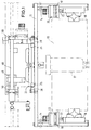
- the screen printing stencil 10 is interposed by mounting slides 18 carried by a U-shaped frame 12, whose two legs 14 are substantially transverse to those of the Screen printing stencil executed during the printing process Movements run and each with one of two rails 15 existing guide for one of the bracket slide 18 provided are, the sliding shoes 16 worn by him along the respective two guide rails 15 for fine adjustment of the Screen printing stencil 10 in the direction of the longitudinal axis of the one to be printed Object 17 is displaceable.
- everyone is an actuator 20 is assigned to the two mounting slides 18, which is fixed to the respective legs 14 via holding plates 19 is appropriate.
- the non-rotatable spindle 22 of the respective Actuator 20 is with the associated mounting slide 18th connected so that an actuation of the servomotor 20 and the this caused an axial displacement of the spindle 22 corresponding axial displacement of the support slide 18 and thus the one attached to the two mounting slides 18 Screen printing stencil 10 causes.
- the frame 12 is opposed by the screen holder 24 carried vertically adjustable.
- the latter is with two in provided essential vertical guide rails 25 on which Slide shoes 28 are guided, which are attached to the support frame 12 are.
- the vertical adjustability of the support frame 12 serves to adjust the height of the screen printing stencil 10 the dimension of the object to be printed such that with a larger Diameter of the object and the screen printing template the support frame 12 may be arranged in a higher position have to. In the respective operating position, the support frame 12 using suitable locking devices on the sieve holder 24 fixed.
- the screen holder 24 is carried by the screen slide 30, the one in the direction of arrows 32, 34 (Fig. 2) back and forth Executes movement and for this purpose with a suitable drive connected is.
- the screen slide is with two guide rails 36 (Fig. 3) provided on which the corresponding Sieve holder 24 provided with sliding shoes 38 also in the direction the arrows 32 and 34 is linearly displaceable.
- the setting the sieve holder 24 by moving accordingly the guide rails 36 is carried out by a servomotor 40 which attached to a plate 41 carried by the sieve slide 30 is.
- the non-rotatable, but axially adjustable spindle 42 is connected to the sieve holder 24, so that an actuation of the servomotor 40 a corresponding linear displacement of the Screen holder 24 and thus the screen printing stencil 10 causes.
- the Clamping cartridge 46 can be actuated in a suitable manner such that between a position in which it is clamped on the spar 48 and a position in which the clamping is released is adjustable. In their effective position, in which the clamping cartridge is firmly connected to the spar 48 by means of clamping is, the driving forces from the screen carriage 30 over the Spar 48 and the clamping cartridge 46 on the screen holder 24 transmitted so that the actuator 40 and the associated spindle 42 are at least largely relieved of these forces.
- the Klammpatrone 46 is only when the screen holder 24th compared to the screen slide using the servomotor 40 is to be moved along the guides 36, solved. After done Adjustment will then put the collet back in its place brought into effective position in which they sieve slides 30 and Sieve holder 24 firmly connected.
- the sieve slide 30 is on its underside with a rod-shaped Section 44 connected from a profile material on which which causes the screen carriage 30 to move back and forth Drive attacks.
- This section 44 of profile material can in the presence of several screen printing stations in the 3 would be arranged one behind the other extend over all printing stations and with the screen slide all printing stations connected and so as a common Serve element for the transmission of the drive movements.
- the holder for the object by means of which the object during of the printing process synchronized with the linear movement of the Screen printing stencil in contact with it around its longitudinal axis or an axis parallel to it is rotated for reasons of Clarity not shown in the drawing.
- the drive for the object holder can z. B. about one rack each from the screen slide or from the common one Profile rail 44 on a connected to the object holder Gear are transmitted. It is a means and configurations to any person skilled in the field of screen printing are common.
Landscapes
- Engineering & Computer Science (AREA)
- Mechanical Engineering (AREA)
- Screen Printers (AREA)
Abstract
Description
- Fig. 1
- die Draufsicht der für die Anbringung einer Siebdruckschablone in einer Druckstation erforderlichen Teile,
- Fig. 2
- die dazugehörige Vorderansicht,
- Fig. 3
- die dazugehörige Seitenansicht.
Claims (9)
- Siebdruckvorrichtung mit wenigstens einer Siebdruckschablone (10), die an einer Siebhalterung (24) angebracht ist, die von einem in Druckrichtung hin- und herbewegbaren Siebschlitten (30) getragen ist, und mit einer Halterung für das zu bedruckende Objekt, die während des Bedruckungsvorganges eine Rotationsbewegung erfährt, sowie einem ersten Antriebsmittel für den Siebsehlitten (30) und die Objekthalterung, dadurch gekennzeichnet, daß zwischen dem ersten Antriebsmittel, welches die Hin- und Herbewegung der Siebdruckschablone (10) während des Bedruckens bewirkt, und der Siebdruckschablone (10) ein zweites Antriebsmittel (40) eingeschaltet ist, durch welches die Siebdruckschablone relativ zum ersten Antriebsmittel in Richtung der beim Bedruckungsvorgang ausgeführten Bewegung und entgegengesetzt dazu einstellbar ist.
- Siebdruckvorrichtung nach Anspruch 1, dadurch gekennzeichnet, daß am Siebschlitten (30) eine Führung (38) für die Siebhalterung (24) angebracht ist, entlang welcher die Siebhalterung (24) linear verschoben werden kann.
- Siebdruckvorrichtung nach Anspruch 1, dadurch gekennzeichnet, daß das zweite Antriebsmittel als Schrittmotor (40) ausgebildet ist.
- Siebdruckvorrichtung nach Anspruch 3, dadurch gekennzeichnet, daß der Schrittmotor (40) vom Siebschlitten (30) getragen und die Spindel (42) des Schrittmotors (40) mit der Siebhalterung (24) verbunden ist.
- Siebdruckvorrichtung nach Anspruch 1, dadurch gekennzeichnet, daß eine lösbare Feststelleinrichtung (46, 48) vorgesehen ist, durch welche Siebhalterung (24) und Siebschlitten (30) unabhängig von dem die Einstellung der Siebhalterung (24) bewirkenden Antrieb miteinander fest verbindbar sind.
- Siebdruckvorrichtung nach Anspruch 1, dadurch gekennzeichnet, daß die Siebhalterung (24) auch in einer senkrecht zu der durch das erste Antriebsmittel bewirkten Bewegung reltiv zum Siebschlitten (30) einstellbar ist.
- Siebdruckvorrichtung nach Anspruch 6, dadurch gekennzeichnet, daß die Siebhalterung (24) mit wenigstens einem Stellmotor (20) versehen ist, mittels welchem die Siebdruckschablone gegenüber der Siebhalterung (24) verschiebbar ist.
- Siebdruckvorrichtung nach Anspruch 1, dadurch gekennzeichnet, daß wenigstens zwei Druckstationen vorgesehen sind, in denen aufeinanderfolgend das Objekt mit einem Einzel-Druckbild versehen wird und sämtliche Einzel-Druckbilder sich zu einem Gesamtdruckbild ergänzen.
- Siebdruckvorrichtung nach Anspruch 1, dadurch gekennzeichnet, daß wenigstens eine Kamera vorgesehen ist, welches das auf dem Objekt befindliche Druckbild erfaßt und im Falle einer Abweichung des Druckbildes auf dem Objekt eine Korrektur der Position der Siebdruckschablone im Bedarfsfall bewirken kann.
Applications Claiming Priority (2)
| Application Number | Priority Date | Filing Date | Title |
|---|---|---|---|
| DE19838983A DE19838983A1 (de) | 1998-08-27 | 1998-08-27 | Siebdruckvorrichtung |
| DE19838983 | 1998-08-27 |
Publications (2)
| Publication Number | Publication Date |
|---|---|
| EP0983847A1 true EP0983847A1 (de) | 2000-03-08 |
| EP0983847B1 EP0983847B1 (de) | 2002-10-23 |
Family
ID=7878905
Family Applications (1)
| Application Number | Title | Priority Date | Filing Date |
|---|---|---|---|
| EP99115234A Expired - Lifetime EP0983847B1 (de) | 1998-08-27 | 1999-08-02 | Siebdruckmaschine |
Country Status (2)
| Country | Link |
|---|---|
| EP (1) | EP0983847B1 (de) |
| DE (2) | DE19838983A1 (de) |
Cited By (3)
| Publication number | Priority date | Publication date | Assignee | Title |
|---|---|---|---|---|
| EP2583829A1 (de) | 2011-10-19 | 2013-04-24 | Krones AG | Bedruckungsvorrichtung für Behälter |
| DE102011122848A1 (de) | 2011-10-19 | 2013-04-25 | Krones Aktiengesellschaft | Bedruckungsvorrichtung für Behälter |
| CN116766747A (zh) * | 2023-08-02 | 2023-09-19 | 四川旭虹光电科技有限公司 | 一种曲面丝印装置 |
Families Citing this family (2)
| Publication number | Priority date | Publication date | Assignee | Title |
|---|---|---|---|---|
| CN100462228C (zh) * | 2007-08-17 | 2009-02-18 | 武汉科技学院 | 可多向调框的丝网印花装置 |
| CN105479931B (zh) * | 2015-12-24 | 2018-01-30 | 武汉纺织大学 | 用于丝网印花的网框的固定与调节装置及其使用方法 |
Citations (5)
| Publication number | Priority date | Publication date | Assignee | Title |
|---|---|---|---|---|
| FR1573070A (de) * | 1967-03-22 | 1969-07-04 | ||
| US3941053A (en) * | 1973-09-27 | 1976-03-02 | James A. Black | Printing press |
| US4084505A (en) * | 1976-06-14 | 1978-04-18 | Shiro Ichinose | Device for adjusting phase of flat screen |
| EP0488092A1 (de) * | 1990-11-27 | 1992-06-03 | FIRMA GERHARD KLEMM MASCHINENFABRIK GMBH & CO. | Siebdruckmaschine |
| US5553547A (en) * | 1995-06-06 | 1996-09-10 | Miller Process Coating Co. | Laser controlled indexer for printing on ware |
Family Cites Families (4)
| Publication number | Priority date | Publication date | Assignee | Title |
|---|---|---|---|---|
| SE8405067L (sv) * | 1984-10-10 | 1986-04-11 | Svecia Silkscreen Maskiner Ab | Anordning for att i en stenciltryckmaskin orientera ett fran ett forsta pa en stencil utbildat monster herrorande andra monster i forhallande till ett for monstret avsett material (samtidig stegmotorpaverkan) |
| DE3730409A1 (de) * | 1987-09-10 | 1989-03-23 | Balsfulland Gmbh Maschf Geb | Siebdruckmaschine |
| US5129155A (en) * | 1990-10-02 | 1992-07-14 | M & R Printing Equipment, Inc. | Automatic screen registration device and method therefor |
| EP0736379A3 (de) * | 1995-03-14 | 1997-08-13 | Salvador Gali | Langtisch-Siebdruckmaschine mit ausgewuchtetem Antrieb und mit hinsichtlich aller Richtungen kompensiertem, justierbarem Rapport |
-
1998
- 1998-08-27 DE DE19838983A patent/DE19838983A1/de not_active Withdrawn
-
1999
- 1999-08-02 EP EP99115234A patent/EP0983847B1/de not_active Expired - Lifetime
- 1999-08-02 DE DE59903154T patent/DE59903154D1/de not_active Expired - Fee Related
Patent Citations (5)
| Publication number | Priority date | Publication date | Assignee | Title |
|---|---|---|---|---|
| FR1573070A (de) * | 1967-03-22 | 1969-07-04 | ||
| US3941053A (en) * | 1973-09-27 | 1976-03-02 | James A. Black | Printing press |
| US4084505A (en) * | 1976-06-14 | 1978-04-18 | Shiro Ichinose | Device for adjusting phase of flat screen |
| EP0488092A1 (de) * | 1990-11-27 | 1992-06-03 | FIRMA GERHARD KLEMM MASCHINENFABRIK GMBH & CO. | Siebdruckmaschine |
| US5553547A (en) * | 1995-06-06 | 1996-09-10 | Miller Process Coating Co. | Laser controlled indexer for printing on ware |
Cited By (4)
| Publication number | Priority date | Publication date | Assignee | Title |
|---|---|---|---|---|
| EP2583829A1 (de) | 2011-10-19 | 2013-04-24 | Krones AG | Bedruckungsvorrichtung für Behälter |
| DE102011084798A1 (de) | 2011-10-19 | 2013-04-25 | Krones Aktiengesellschaft | Bedruckungsvorrichtung für Behälter |
| DE102011122848A1 (de) | 2011-10-19 | 2013-04-25 | Krones Aktiengesellschaft | Bedruckungsvorrichtung für Behälter |
| CN116766747A (zh) * | 2023-08-02 | 2023-09-19 | 四川旭虹光电科技有限公司 | 一种曲面丝印装置 |
Also Published As
| Publication number | Publication date |
|---|---|
| DE19838983A1 (de) | 2000-03-02 |
| DE59903154D1 (de) | 2002-11-28 |
| EP0983847B1 (de) | 2002-10-23 |
Similar Documents
| Publication | Publication Date | Title |
|---|---|---|
| DE10008215B4 (de) | Druckwerk für eine Rotationsdruckmaschine mit Kreuzschlitten | |
| DE3886979T2 (de) | Stanzvorrichtung für dünne Platten und in der Vorrichtung verwendete Stanzeinheiten. | |
| DE1786507C3 (de) | ||
| EP0488092B1 (de) | Siebdruckmaschine | |
| EP0949071B1 (de) | Zusatzeinrichtung für ein Druckwerk | |
| DE3119398C2 (de) | Vorrichtung zur Einstellung der Länge einer zu bedruckenden Bahn in einer Rollenrotationsdruckmaschine | |
| EP0802054B1 (de) | Verfahren und Vorrichtung zum Bedrucken von selbsttragenden Einzelobjekten | |
| EP1075943B1 (de) | Druckwerk | |
| EP0983847B1 (de) | Siebdruckmaschine | |
| DE4307733A1 (de) | Druckmaschine mit auswechselbarem Druckkopf | |
| DE10223666B4 (de) | Farbwerksaufbau bei Flexodruckmaschinen | |
| EP0279393B1 (de) | Verstellbare Speicherkassette für Druckprodukte | |
| EP1592556B1 (de) | Druckwerk einer druckmaschine | |
| DE3142794A1 (de) | Siebdruckverfahren und -vorrichtung | |
| DE4035036C2 (de) | Einrichtung zur axialen Einstellung von Saugringen in Bogenbremsen von Druckmaschinen | |
| DE3933678C2 (de) | ||
| DE4030864C2 (de) | ||
| EP0576878A1 (de) | Vorrichtung zum Auswechseln und Justieren eines Werkzeugs im Werkzeugeinbauraum einer Presse | |
| DE4039827A1 (de) | Vorrichtung zum einstellen des parallelen abstands zweier werkzeuge an einer numerisch gesteuerten werkzeugmaschine | |
| DE2438735A1 (de) | Seriendruckwerk | |
| DE2725725A1 (de) | Flachoffsetpresse | |
| DE4209006C2 (de) | Stelleinrichtung für mehrere Bogenführungs- und Leitelemente | |
| DE4312726C2 (de) | Tampondruckmaschine | |
| DE2807333C2 (de) | Vorrichtung zum Einstellen eines Druckwerks | |
| DE3444561A1 (de) | Steuermechanismus fuer das farbwerk einer druckmaschine |
Legal Events
| Date | Code | Title | Description |
|---|---|---|---|
| PUAI | Public reference made under article 153(3) epc to a published international application that has entered the european phase |
Free format text: ORIGINAL CODE: 0009012 |
|
| AK | Designated contracting states |
Kind code of ref document: A1 Designated state(s): DE |
|
| AX | Request for extension of the european patent |
Free format text: AL;LT;LV;MK;RO;SI |
|
| 17P | Request for examination filed |
Effective date: 20000512 |
|
| AKX | Designation fees paid |
Free format text: DE |
|
| 17Q | First examination report despatched |
Effective date: 20001108 |
|
| GRAG | Despatch of communication of intention to grant |
Free format text: ORIGINAL CODE: EPIDOS AGRA |
|
| GRAG | Despatch of communication of intention to grant |
Free format text: ORIGINAL CODE: EPIDOS AGRA |
|
| GRAG | Despatch of communication of intention to grant |
Free format text: ORIGINAL CODE: EPIDOS AGRA |
|
| GRAH | Despatch of communication of intention to grant a patent |
Free format text: ORIGINAL CODE: EPIDOS IGRA |
|
| GRAH | Despatch of communication of intention to grant a patent |
Free format text: ORIGINAL CODE: EPIDOS IGRA |
|
| GRAA | (expected) grant |
Free format text: ORIGINAL CODE: 0009210 |
|
| AK | Designated contracting states |
Kind code of ref document: B1 Designated state(s): DE |
|
| REF | Corresponds to: |
Ref document number: 59903154 Country of ref document: DE Date of ref document: 20021128 |
|
| PLBE | No opposition filed within time limit |
Free format text: ORIGINAL CODE: 0009261 |
|
| STAA | Information on the status of an ep patent application or granted ep patent |
Free format text: STATUS: NO OPPOSITION FILED WITHIN TIME LIMIT |
|
| 26N | No opposition filed |
Effective date: 20030724 |
|
| PGFP | Annual fee paid to national office [announced via postgrant information from national office to epo] |
Ref country code: DE Payment date: 20041028 Year of fee payment: 6 |
|
| PG25 | Lapsed in a contracting state [announced via postgrant information from national office to epo] |
Ref country code: DE Free format text: LAPSE BECAUSE OF NON-PAYMENT OF DUE FEES Effective date: 20060301 |