EP0983757A2 - Vorrichtung zur Chirurgie der Hornhaut - Google Patents
Vorrichtung zur Chirurgie der Hornhaut Download PDFInfo
- Publication number
- EP0983757A2 EP0983757A2 EP99117382A EP99117382A EP0983757A2 EP 0983757 A2 EP0983757 A2 EP 0983757A2 EP 99117382 A EP99117382 A EP 99117382A EP 99117382 A EP99117382 A EP 99117382A EP 0983757 A2 EP0983757 A2 EP 0983757A2
- Authority
- EP
- European Patent Office
- Prior art keywords
- cornea
- corneal
- optical system
- laser beam
- unit
- Prior art date
- Legal status (The legal status is an assumption and is not a legal conclusion. Google has not performed a legal analysis and makes no representation as to the accuracy of the status listed.)
- Granted
Links
Images


Classifications
-
- A—HUMAN NECESSITIES
- A61—MEDICAL OR VETERINARY SCIENCE; HYGIENE
- A61B—DIAGNOSIS; SURGERY; IDENTIFICATION
- A61B3/00—Apparatus for testing the eyes; Instruments for examining the eyes
- A61B3/10—Objective types, i.e. instruments for examining the eyes independent of the patients' perceptions or reactions
- A61B3/107—Objective types, i.e. instruments for examining the eyes independent of the patients' perceptions or reactions for determining the shape or measuring the curvature of the cornea
-
- A—HUMAN NECESSITIES
- A61—MEDICAL OR VETERINARY SCIENCE; HYGIENE
- A61F—FILTERS IMPLANTABLE INTO BLOOD VESSELS; PROSTHESES; DEVICES PROVIDING PATENCY TO, OR PREVENTING COLLAPSING OF, TUBULAR STRUCTURES OF THE BODY, e.g. STENTS; ORTHOPAEDIC, NURSING OR CONTRACEPTIVE DEVICES; FOMENTATION; TREATMENT OR PROTECTION OF EYES OR EARS; BANDAGES, DRESSINGS OR ABSORBENT PADS; FIRST-AID KITS
- A61F9/00—Methods or devices for treatment of the eyes; Devices for putting-in contact lenses; Devices to correct squinting; Apparatus to guide the blind; Protective devices for the eyes, carried on the body or in the hand
- A61F9/007—Methods or devices for eye surgery
- A61F9/008—Methods or devices for eye surgery using laser
- A61F9/00802—Methods or devices for eye surgery using laser for photoablation
- A61F9/00804—Refractive treatments
-
- A—HUMAN NECESSITIES
- A61—MEDICAL OR VETERINARY SCIENCE; HYGIENE
- A61F—FILTERS IMPLANTABLE INTO BLOOD VESSELS; PROSTHESES; DEVICES PROVIDING PATENCY TO, OR PREVENTING COLLAPSING OF, TUBULAR STRUCTURES OF THE BODY, e.g. STENTS; ORTHOPAEDIC, NURSING OR CONTRACEPTIVE DEVICES; FOMENTATION; TREATMENT OR PROTECTION OF EYES OR EARS; BANDAGES, DRESSINGS OR ABSORBENT PADS; FIRST-AID KITS
- A61F9/00—Methods or devices for treatment of the eyes; Devices for putting-in contact lenses; Devices to correct squinting; Apparatus to guide the blind; Protective devices for the eyes, carried on the body or in the hand
- A61F9/007—Methods or devices for eye surgery
- A61F9/008—Methods or devices for eye surgery using laser
- A61F2009/00844—Feedback systems
- A61F2009/00846—Eyetracking
-
- A—HUMAN NECESSITIES
- A61—MEDICAL OR VETERINARY SCIENCE; HYGIENE
- A61F—FILTERS IMPLANTABLE INTO BLOOD VESSELS; PROSTHESES; DEVICES PROVIDING PATENCY TO, OR PREVENTING COLLAPSING OF, TUBULAR STRUCTURES OF THE BODY, e.g. STENTS; ORTHOPAEDIC, NURSING OR CONTRACEPTIVE DEVICES; FOMENTATION; TREATMENT OR PROTECTION OF EYES OR EARS; BANDAGES, DRESSINGS OR ABSORBENT PADS; FIRST-AID KITS
- A61F9/00—Methods or devices for treatment of the eyes; Devices for putting-in contact lenses; Devices to correct squinting; Apparatus to guide the blind; Protective devices for the eyes, carried on the body or in the hand
- A61F9/007—Methods or devices for eye surgery
- A61F9/008—Methods or devices for eye surgery using laser
- A61F2009/00861—Methods or devices for eye surgery using laser adapted for treatment at a particular location
- A61F2009/00872—Cornea
-
- A—HUMAN NECESSITIES
- A61—MEDICAL OR VETERINARY SCIENCE; HYGIENE
- A61F—FILTERS IMPLANTABLE INTO BLOOD VESSELS; PROSTHESES; DEVICES PROVIDING PATENCY TO, OR PREVENTING COLLAPSING OF, TUBULAR STRUCTURES OF THE BODY, e.g. STENTS; ORTHOPAEDIC, NURSING OR CONTRACEPTIVE DEVICES; FOMENTATION; TREATMENT OR PROTECTION OF EYES OR EARS; BANDAGES, DRESSINGS OR ABSORBENT PADS; FIRST-AID KITS
- A61F9/00—Methods or devices for treatment of the eyes; Devices for putting-in contact lenses; Devices to correct squinting; Apparatus to guide the blind; Protective devices for the eyes, carried on the body or in the hand
- A61F9/007—Methods or devices for eye surgery
- A61F9/008—Methods or devices for eye surgery using laser
- A61F2009/00897—Scanning mechanisms or algorithms
-
- A—HUMAN NECESSITIES
- A61—MEDICAL OR VETERINARY SCIENCE; HYGIENE
- A61F—FILTERS IMPLANTABLE INTO BLOOD VESSELS; PROSTHESES; DEVICES PROVIDING PATENCY TO, OR PREVENTING COLLAPSING OF, TUBULAR STRUCTURES OF THE BODY, e.g. STENTS; ORTHOPAEDIC, NURSING OR CONTRACEPTIVE DEVICES; FOMENTATION; TREATMENT OR PROTECTION OF EYES OR EARS; BANDAGES, DRESSINGS OR ABSORBENT PADS; FIRST-AID KITS
- A61F9/00—Methods or devices for treatment of the eyes; Devices for putting-in contact lenses; Devices to correct squinting; Apparatus to guide the blind; Protective devices for the eyes, carried on the body or in the hand
- A61F9/007—Methods or devices for eye surgery
- A61F9/008—Methods or devices for eye surgery using laser
- A61F9/00802—Methods or devices for eye surgery using laser for photoablation
- A61F9/00814—Laser features or special beam parameters therefor
Definitions
- the present invention relates to a corneal surgery apparatus for ablating a part of a cornea of a patient's eye to correct a refractive error of the eye or to remove a lesion therefrom.
- a corneal surgery apparatus that ablates a corneal stroma of a patient's eye with an excimer laser or the like to change a refractive power of the eye to correct ametropia including myopia, hypermetropia, astigmatism and the like, or to remove an affected part of the cornea such as opacity.
- a corneal shape measurement apparatus hereinafter referred to as a topography apparatus
- a topography apparatus projects a placido ring onto a cornea and photographs an image of the placido ring to measure the corneal surface shape.
- An amount to be ablated is calculated from the data and also the post-operative refractive power to be obtained. The ablation is carried out in accordance with the calculated ablation amount.
- One of the problems lies in the case of measuring a corneal shape of a patient's eye by a topography apparatus first, and then performing surgery to correct the refractive power by a separate corneal surgery apparatus based on the data captured from the topography apparatus.
- the positional relationship between the topography apparatus and the patient's eye is not necessarily the same as the positional relationship between the corneal surgery apparatus and the patient's eye. It is especially so, when the measurement by the topography apparatus is carried out with the patient being sit and fixed by the face, while the surgery by the corneal surgery apparatus is carried out with the patient being laid on his back.
- the post-operative corneal shape may differ from the expected one and the refractive error may not be corrected as expected.
- One possible way to address the above problem is to combine the corneal surgery apparatus and the topography apparatus into one apparatus so as to make the topography position and the corneal surgery position coincide with each other relative to the patient's eye.
- the topography apparatus including a placido ring projecting unit and a TV camera for photographing its corneal reflex and the like
- the corneal surgery apparatus including a laser irradiation optical system and an observation optical system will results in an undesirably large apparatus.
- the present invention has been made in view of the above circumstances and has an object to overcome the above problems and to provide an apparatus for corneal surgery which is small and compact, while being capable of preventing displacement between a corneal shape measurement position and a laser beam irradiation position upon corneal surgery to remove a part of the cornea with a laser.
- a corneal surgery apparatus which ablates corneal tissue with a laser beam
- the apparatus comprises an irradiation unit including a light directing optical system for directing the laser beam to an intended range on a cornea of a patient's eye, wherein the laser beam has a wavelength in a far ultra-violet region and intensity capable of causing ablation and a corneal shape measurement unit, provided inside the apparatus, for measuring a three-dimensional shape of the cornea
- the corneal shape measurement unit including a measurement light projecting optical system for projecting measurement light onto the cornea and its convergent point is shifted by moving a focusing lens along an optical axis
- a measurement light receiving optical system including a photo-detector for receiving reflected light from the cornea and its convergent point is shifted by moving a focusing lens along an optical axis
- a scanning unit for shifting a projection spot of the measurement light on the cornea in XY directions
- the corneal thickness can be measured so that judgement on ablation or adjustment of the ablation amount may be made based on the measured corneal thickness.
- Fig. 1 is a view showing an overall configuration of a corneal surgery apparatus of the present invention.
- the reference numeral 1 is a main body of the surgery apparatus and optical systems and a control system are partially embedded therein.
- 2 is an arm portion for directing a laser beam to a patient's eye.
- An end portion 2a of the arm portion 2 is provided with a binocular microscope unit 3 for observing the patient's eye, an illumination unit 4 and the like.
- the end portion 2a may be moved in X, Y and Z directions by a driving device.
- 5 is a controller provided with a joystick 6 for signaling to move the arm portion 2 (the end portion 2a) in X and Y directions and also with various operation switches.
- 7 is a foot switch for signaling to irradiate a laser beam.
- 8 is a computer to perform input of various data about surgical conditions as well as to perform arithmetic, storage and display of corneal shape data, ablation data and the like.
- 9 is a bed on which the patient lies down.
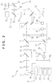
- Fig. 2 is a view showing a schematic configuration of the optical systems and the control system of the corneal surgery apparatus of the present invention. Concerning the optical systems, descriptions are given separately to a corneal shape measurement optical system, a laser irradiation optical system, an observation optical system and an eyeball position detecting optical system.
- 10 is the corneal shape measurement optical system for measuring a three-dimensional corneal shape.
- 11 is a laser beam source for emitting a laser beam which functions as measurement light to measure the corneal shape.
- an infrared semiconductor laser beam source that emits infrared laser at a wavelength of 800 nm is used.
- the measurement light does not necessarily have to be infrared light, yet it is advantageous in that infrared light is not glaring and therefore the discomfort of the patient upon a measurement is reduced.
- 12 is a focusing lens
- 13 is a pinhole (aperture)
- 14 is a polarizing beamsplitter.
- 15 is a collimating lens that makes the infrared laser beam a parallel beam
- 16 is a quarter waveplate.
- the 17 is a dichroic mirror by which an optical axis of a laser irradiation optical system 25 described later is made coaxial with an optical axis of the measurement optical system 10.
- the dichroic mirror 17 transmits the infrared laser beam that the laser beam source 11 emits but reflects an excimer laser beam that an excimer laser head 26, mentioned later, emits.
- 18 is a focusing lens for focusing the infrared laser beam and the excimer laser beam.
- the lens 18 is arranged movably back and forth along the optical axis.
- 19 and 20 are scanning mirrors which scan the infrared laser beam and the excimer laser beam over the cornea in two-dimensional directions. In this embodiment, a galvano-mirror is used as the scanning mirrors 19 and 20 respectively.
- the dichroic mirror 21 is a dichroic mirror by which the common optical axis of the measurement optical system 10 and the laser irradiating optical system 25 is made coaxial with a common optical axis of an observation optical system 30 and an eyeball position detecting optical system 35 described later.
- the dichroic mirror 21 reflects the infrared laser beam having a wavelength of 800 nm emitted from the laser beam source 11 as well as the excimer laser beam having a wavelength of 193 nm, but transmits visible light having a wavelength in a range of about 400-700 nm as well as the infrared laser beam having a wavelength of 950 nm emitted from infrared illumination light sources 34 described later.
- the reference letter E denotes a/the cornea of the patient's eye.
- the scanning mirrors 19 and 20, and also the dichroic mirror 21 are provided inside the end portion 2a.
- the 22 is a pinhole (aperture)
- 23 is a photo-detector that detects the infrared laser beam being measurement light reflected from the cornea E.
- the pinhole 13 and the pinhole 22 are arranged to be conjugate with each other relative to the cornea E.
- the lens 18 also serves the function of making the reflected light from the cornea E parallel light and the lens 15 also serves the function of focusing/converging the reflected light.
- a laser head 26 irradiates a laser beam, which has no thermal effect on a corneal tissue, for ablation upon corneal surgery.
- Used in this embodiment is an ArF excimer laser head that emits an ArF excimer laser beam having a wavelength of 193 nm.
- This therapeutic laser beam has to be a laser beam having its wavelength in a far ultraviolet region to ablate corneal tissue. It is desirable to use a laser beam having a wavelength of 150-230 nm, and more preferably, an ArF laser beam having a wavelength of 193 nm.
- 27 is a mirror that reflects the excimer laser beam emitted from the laser head 26.
- the excimer laser beam emitted from the laser head 26 is reflected and deflected first by the mirror 27 and then by the dichroic mirror 17. Thereafter, the excimer laser beam passes through the lens 18 and is sequentially reflected and deflected by the scanning mirrors 19 and 20, and finally by the dichroic mirror 21, thereby being directed onto the cornea E.
- the observation optical system 30 is the observation optical system for observing the patient's eye.
- 31 is an objective lens.
- 32 is a dichroic mirror that transmits visible light, but reflects the infrared light having a wavelength of 950 nm emitted by the infrared illumination light sources 34.
- Visible illumination light from the illumination unit 4 illuminates an anterior part of the patient's eye and forms an image thereof.
- Luminous flux of the image passes through the dichroic mirror 21, the lens 31 and the dichroic mirror 32, and then enters the microscope unit 3. Consequently, a surgeon can observe the patient's eye with the binocular microscope unit 3.
- the observation optical system 30 includes a not illustrated reticle plate inserted therein. This allows to provide a reference for alignment of the patient's eye in X and Y directions.
- observation optical system 30 Also included in the observation optical system 30 is a target projecting optical system comprising two slits (reference may be made to Japanese Published Unexamined Patent Application HEI 6-47001 that corresponds to USP 5,562,656 by the present applicant).
- the observation optical system 30 is arranged inside the end portion 2a.
- 33 is a fixation light arranged on the optical axis of the observation optical system 30 and emits visible light.
- 35 is the eyeball position detecting optical system for detecting the eyeball position of the patient's eye.
- 34 are the infrared illumination light sources which emit infrared light at a wavelength of 950 nm and a total of four illumination light sources 34 are arranged at 90 ° intervals about the optical axis.
- 36 is a photographing lens and 37 is a mirror.
- 38 is an infrared light transmitting filter to cut off noise light.
- 39 is a CCD camera.
- the eyeball position detecting optical system 35 is also arranged inside the end portion 2a.
- the luminous flux of the image of the anterior part of the patient's eye illuminated by the illumination light sources 34 passes through the dichroic mirror 21 and the lens 31, and then is reflected by the dichroic mirror 32. Thereafter, the luminous flux passes through the photographing lens 36 thereby forming an image on a photographing surface of the camera 39 via the mirror 37 and the filter 38. Upon the passage of the luminous flux, the filter 38 cuts off the visual light reflected slightly by the dichroic mirror 32.
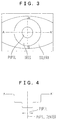
- Fig. 3 is a view showing the image of the anterior part of the eye captured by the camera 39 and Fig. 4 is a view showing distribution of the light along the line A-A' (shown in Fig.3) obtained from photographing signals of the camera 39.
- the light distribution differs depending on its corresponding part of the eye such as a pupil, an iris and a sclera. Accordingly, from information about the light distribution, coordinates of each pupil edge along its lateral direction are detect. Further, from the coordinates of the pupil edge detected thereby, coordinates of its center in the lateral direction are as well obtained.
- coordinates of a center of the pupil in its vertical direction are obtained from information about the light distribution along the vertical line B-B' (shown in Fig.3). That is to say, the light distribution along the two lines allows to locate the pupil center with respect to the optical axis of the detecting optical system 35 (equally meaning the optical axes of the measurement optical system 10 and the irradiating optical system 25) being adjusted to have a predetermined positional relationship on the photographing element of the camera 39.
- the control system 40 is a control system embedded within the main body 1.
- the control system 40 drives and controls the laser beam source 11, the lens 18, the scanning mirrors 19 and 20, the laser head 26, the fixation light 33, the illumination light sources 34 and the like.
- 41, 42, 43, 44 are respectively an input unit (a key board, a mouse and the like), a arithmetic analytical processing unit (CPU and the like), a display unit (a monitor), and an output unit (a printer, a floppy disk drive and the like) all of which are provided to the computer 8.
- the input unit 41 is used to input laser irradiation conditions such as an intended post-operative refractive power, a corneal radius and the like.
- the processing unit 42 processes signals from the photo-detector 23 thereby obtaining corneal shape data.
- the processing unit 42 also processes the corneal shape data and the inputted irradiation conditions thereby obtaining ablation data such as an amount of the cornea to be ablated and the like.
- the data processed by the processing unit 42 is sent to the control unit 40.
- the control unit 40 drives and controls the scanning mirrors 19 and 20, the laser head 26 and the like.
- the display unit 43 displays both the pre-operative corneal shape and post-operative corneal shape along with other information in accordance with the corneal shape data sent from the processing unit 42.
- the output unit 44 outputs various obtained data.
- a driving circuit for the arm portion 2 is also controlled by the control unit 40.
- the surgeon first makes the patient lie on the bed 9 and places the arm portion 2 (the end portion 2a) above the patient's eye. Thereafter, the surgeon lights the illumination unit 4, the fixation light 33, the illumination light sources 34 and the like and then makes the patient's eye fixate at the fixation light 33. While observing the anterior part of the patient's eye being illuminated by the illumination unit 4 with the microscope unit 3, the surgeon operates the joystick 6 to make alignment in X and Y directions so as to bring a not illustrated reticle and the pupil into a predetermined positional relationship with each other. In addition, the surgeon operates a focus adjusting switch 60 to perform alignment in a Z direction.
- control unit 40 When signals generated in response to the operations of the joystick 6 (and the switch 60) are inputted to the control unit 40, the control unit 40 actuates the driving circuit for the arm portion 2 so as to move the arm portion 2 (the end portion 2a) in X and Y directions (and also in a Z direction).
- an auto-alignment changeover switch 61 provided on the controller 5 is turned on, an auto-alignment starts.
- the control unit 40 moves the arm portion 2 (the end portion 2a) in X and Y directions so as to bring the optical axes of the measurement optical system 10 and the irradiating optical system 25 into coincidence with the pupil center.
- the surgeon depresses a ready switch 62 provided on the controller 5 after turning on the auto-alignment changeover switch 61 and completing the alignment.
- a ready switch 62 When the ready switch 62 is depressed, a predetermined position on the photographing element is stored as a reference position and an eyeball tracking mechanism (auto-tracking) is actuated thereby moving the arm portion 2 (the end portion 2a) so as to bring the reference position into coincidence with the pupil center.
- the measurement optical system 10 When the alignment of the patient's eye is completed, a three-dimensional shape of the cornea E is measured by the measurement optical system 10.
- the infrared laser beam of the linearly polarized light emitted from the laser beam source 11 converges via the lens 12 on the pinhole 13. After converging and passing through the pinhole 13, the infrared laser beam passes though the beam splitter 14, because the laser beam source is arranged to adapt its polarization direction, and then is made parallel light by the lens 15. Thereafter, the linearly polarized light is converted into circularly polarized light by the quater waveplate 16, which is arranged to form an angle of 45 ° between its retarder principal plane and the polarization plane of the infrared laser beam.
- the infrared laser beam passes through the dichroic mirror 17 and converges via the lens 18. Finally, the infrared laser beam is successively reflected and deflected by the scanning mirrors 19 and 20 to converge in the vicinity of the cornea E. Through controlling the reflection angles (deflection angles) of the scanning mirrors 19 and 20, the infrared laser beam comes to scan in two-dimensional directions.
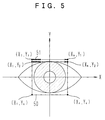
- Fig. 5 is a view explaining the scan with the measurement light over the cornea in two-dimensional directions.
- the control unit 40 drives the scanning mirrors 19 and 20 via the respective driving circuits 47 and 48 thereby scanning the infrared laser beam 51 being the measurement light over a scanning range starting from the top left to the bottom right in succession of (X 1 , Y 1 ) ⁇ (X n , Y 1 ), (X 1 , Y 2 ) ⁇ (X n , Y 2 ) ⁇ (X 1 , Y n ) ⁇ (X n , Y n ).
- the infrared laser beam reflected by the cornea E is reflected and deflected successively by the scanning mirrors 20 and 19 and then made to be parallel beam again by the lens 18. Thereafter, the infrared laser beam passes through the dichroic mirror 17 and is converted from circularly polarized light into linearly polarized light by the quater waveplate 16. After being converged by the lens 15, the infrared laser beam of the linearly polarized light is reflected by the polarizing beamsplitter 14 because its polarization direction is rotated 90° from the polarization direction at the time the infrared laser beam runs toward the cornea E. The infrared laser beam converges on, and passes through, the pinhole 22 and enters into the photo-detector 23.
- the corneal surface anterior surface or posterior surface
- the infrared laser beam reflected therefrom goes back through the same optical path as described above and converges on the pinhole 22.
- relatively large quantity of light enters into the photo-detector 23.
- the corneal surface anterior surface or posterior surface
- the corneal surface is not on the two-dimensional flat surface (or may be curved surface) over which the convergent point of the infrared laser beam scans, in other words when the infrared laser beam is reflected off the convergent point, as shown in Fig.
- the reflected infrared laser beam does not converge on the pinhole 22 and become blurred. As the result, almost no light enters into the photo-detector 23. Accordingly, when scanning the convergent point of the infrared laser beam over the two-dimensional flat surface, the reflected light is sufficiently detected by the photo-detector 23 only where the corneal surface is within the surface. This allows to obtain a contour of the cornea E on the surface.
- the pinholes 13 and 22 are arranged to be conjugate with each other relative to the cornea E, and thereby forming a confocal optical system (that is to say a point light source and a point detector are in image forming relation with each other relative to one point of an object).
- control unit 40 moves the lens 18 via the driving circuit 46 along the optical axis so that the two-dimensional flat surface over which the convergent point of the infrared laser beam scans is gradually shifted in the direction of the thickness of the cornea.
- the contour of the cornea E on the surface is measured repeatedly in the same way mentioned above but gradually shifted in the direction of the thickness.
- Detection signals from the photo-detector 23 are fed into the processing unit 42 via the control unit 40 and the processing unit 42 obtains three-dimensional corneal shape data based on the detection signals and irradiation spots by the infrared laser beam in three-dimensional directions (the irradiation spots are calculated from the deflection angles of the scanning mirrors and the position of the lense 18).
- the corneal thickness is obtained based on the anterior and posterior shapes of the cornea E.
- a map 70, a sectional view 71 and other numeral data are displayed on the display unit 43.
- the surgeon After completing the corneal shape measurement by the measurement optical system 10, the surgeon inputs intended post-operative corneal data such as refractive power, corneal radius and the like with the use of the input unit 41 (the data may be inputted in advance).
- the processing unit 42 determines ablation data such as necessary amount to be ablated and the like to correct refractive error based on the corneal shape data obtained through the measurement by the measurement optical system 10 and the post-operative corneal data inputted by the surgeon.
- the ablation data determined thereby is displayed on the display unit 43 in superposed relation with the map 70 and the sectional image 71 and other data. Also, the ablation thickness (ablation depth) and the ablation range are displayed numerically. (See Fig.
- the predicted post-operative refractive power and corneal radius are also displayed (not illustrated). Further, it is possible to designate a desired point by moving a cursor 72 on the map 70 so as to display corneal thickness and ablation thickness corresponding to each designated point as display 73 on the display.
- the surgeon checks the map 70, the sectional image 71, the post-operative refractive power and the other data displayed on the display 43 to make sure that there is no problem. Having confirmed that there is no problem, the surgeon goes on to corneal surgery to ablate the cornea with an excimer laser beam.
- the surgeon operates the foot switch 7 to transmit laser irradiating signals to the control unit 40.
- the control unit 40 controls the irradiating optical system 25 (the driving circuits 47, 48 and 49) to perform ablation of the cornea in the way described later.
- the apparatus is not provided with the auto tracking mechanism, the alignment of the apparatus with the patient's eye needs to be performed again before irradiating the laser.
- the control unit 40 drives the laser head 26 via the driving circuit 49 to emit the excimer laser beam.
- the emitted excimer laser beam is reflected and deflected by the mirror 27 and the dichroic mirror 17 and then converged by the lens 18.
- the control unit 40 drives the scanning mirrors 19 and 20 via the driving circuits 47 and 48 respectively so as to aim the excimer laser beam at any intended spot.
- the excimer laser beam is made scan by the scanning mirrors 19 and 20 in the two-dimensional directions within the determined irradiation (ablation) range.
- the scan with the excimer laser beam in the two-dimensional directions may be done in linearly directions similarly to the scanning with the infrared laser beam for the corneal shape measurement, or in concentrically directions (direction as if to draw concentric circles or a spiral).
- the control unit 40 drives the laser head 26 via the driving circuit 49 to irradiate the excimer laser for the duration of the number of pulses (irradiation time) corresponding to the necessary ablation amount.
- the excimer laser being controlled in the aforementioned way is irradiated at each scanning spot within the irradiation (ablation) range so as to ablate the corneal tissue needs to be removed for the refractive error correction. As the result, the patient's eye will have the intended refractive power.
- the information about the corneal thickness is obtained, advantage of the information may be taken to perform surgery more appropriately. For example, comparison may be made between the determined amount of the cornea to be ablated and the thickness of the cornea to figure out the predicted thickness of the post-operative cornea (the thickness of the residual cornea after the ablation). If it is figured that the post-operative cornea is to be thinner than a predetermined standard, the irradiation of the laser is cancelled. Instead, the display unit 43 displays a warning or a not illustrated sound generator produce beep tones for warning. In addition, the laser head 26 and other components are controlled so as to irradiate the laser beam only when the thickness of the post-operative cornea is equal to, or thicker than the predetermined standard.
- the processing unit 42 may be made to adjust the ablation data (the irradiation range of the excimer laser and the like) so that the post-operative cornea is ensured to be thicker than the predetermined standard.
- the standard for the thickness of the post-operative cornea is determined with the use of the input unit 41.
- the irradiation conditions such as the irradiation range and the ablation depth are inputted by operating the input unit 41.
- the comparison is made between the determined amount of the cornea to be ablated and the thickness of the cornea.
- the irradiation of the laser beam is controlled based on the result of the comparison.
- the thickness of the post-operative cornea may be inputted after confirming the pre-operative corneal shape displayed on the display unit 43.
- the optical axis of the measurement optical system 10 and that of the irradiation optical system 25 are made coaxial, a solution is presented to the conventional problem that the positional relationship between the patient's eye and the corneal shape measurement (topography) apparatus differs from the positional relationship between the patient's eye and the corneal surgery apparatus.
- the difference in the state of the patient's eye due to the difference in the position of the patient.
- the optical axis of the measurement optical system 10 and that of the irradiating optical system 25 do not necessarily have to be coaxial as long as the two optical axes have the known predetermined positional relationship therebetween. Yet, it is easier to control irradiation spot and the like if the two optical axes coincide with each other.
- the laser beam having a small circular section is scanned by the galvano-mirror.
- a solution is provided also to another problem associated with a conventional apparatus which combines a placido ring projecting unit and a TV camera provided in a topography apparatus for photographing its corneal reflex and a laser irradiating optical system and an observation optical system provided in a corneal surgery apparatus.
- Making the two optical axes coaxial solves this problem of complication and enlargement of the apparatus.
- the corneal thickness is obtained through measuring the three-dimensional shapes of the anterior and the posterior cornea, determination may be made as to whether to proceed with the ablation or to warn the surgeon when the thickness of the post-operative cornea is expected to be thinner than that of the standard post-operative cornea. This eliminates the possibility of ablation when it should not be done.
- the auto-alignment and the auto-tracking by the eyeball position detecting optical system in this embodiment may possibly be omitted.
- the display of the corneal shape data may be modified to display more variety of data.
- the projecting optical system that projects the infrared laser beam being the measurement light onto the cornea E and the optical system that directs the reflected right from the cornea E to the photo-detector 23 are partially shared with each other.
- the two optical systems may be replaced with two totally separated optical systems.
- the pinhole 13 and the pinhole 22 have to be arranged conjugate with each other relative to the cornea E.
Applications Claiming Priority (4)
| Application Number | Priority Date | Filing Date | Title |
|---|---|---|---|
| JP25152098 | 1998-09-04 | ||
| JP25152098 | 1998-09-04 | ||
| JP15610299 | 1999-06-03 | ||
| JP15610299A JP3848492B2 (ja) | 1998-09-04 | 1999-06-03 | 角膜手術装置 |
Publications (3)
| Publication Number | Publication Date |
|---|---|
| EP0983757A2 true EP0983757A2 (de) | 2000-03-08 |
| EP0983757A3 EP0983757A3 (de) | 2001-09-19 |
| EP0983757B1 EP0983757B1 (de) | 2006-07-05 |
Family
ID=26483933
Family Applications (1)
| Application Number | Title | Priority Date | Filing Date |
|---|---|---|---|
| EP99117382A Expired - Lifetime EP0983757B1 (de) | 1998-09-04 | 1999-09-03 | Vorrichtung zur Chirurgie der Hornhaut |
Country Status (4)
| Country | Link |
|---|---|
| US (1) | US6585723B1 (de) |
| EP (1) | EP0983757B1 (de) |
| JP (1) | JP3848492B2 (de) |
| DE (1) | DE69932208T2 (de) |
Cited By (14)
| Publication number | Priority date | Publication date | Assignee | Title |
|---|---|---|---|---|
| WO2001028479A1 (fr) * | 1999-10-21 | 2001-04-26 | Nidek Co., Ltd. | Dispositif pour determiner la quantite de cornee a enlever et dispositif de chirurgie corneenne |
| WO2003101355A1 (de) * | 2002-05-31 | 2003-12-11 | Carl Zeiss Meditec Ag | Verfahren zur steuerung einer vorrichtung zur behandlung des menschlichen auges |
| EP1584310A1 (de) * | 2004-04-09 | 2005-10-12 | 20/10 Perfect Vision Optische Geräte GmbH | Strahlablenkungssystem für die Hornhaut-Laser-Chirurgie |
| EP2111831A1 (de) * | 2008-04-22 | 2009-10-28 | WaveLight AG | Einrichtung fuer die laseroptische Augenchirurgie |
| WO2009146906A2 (de) * | 2008-06-05 | 2009-12-10 | Carl Zeiss Meditec Ag | Ophthalmologisches lasersystem und betriebsverfahren |
| WO2010051975A1 (de) * | 2008-11-06 | 2010-05-14 | Carl Zeiss Meditec Ag | Ophthalmologisches lasersystem und betriebsverfahren |
| WO2010070020A2 (de) * | 2008-12-17 | 2010-06-24 | Carl Zeiss Meditec Ag | Ophthalmologisches lasersystem und betriebsverfahren |
| EP2382915A3 (de) * | 2006-04-11 | 2012-02-22 | Neuroptix Corporation | Augenabbildung |
| US8955969B2 (en) | 2006-04-11 | 2015-02-17 | Cognoptix, Inc. | Ocular imaging |
| CN104713577A (zh) * | 2015-04-09 | 2015-06-17 | 中国北方车辆研究所 | 激光接收光轴与可见光光轴平行性调校系统及调校方法 |
| US9220403B2 (en) | 2010-08-16 | 2015-12-29 | Cognoptix, Inc. | System and method for detecting amyloid proteins |
| US10182942B2 (en) | 2008-06-05 | 2019-01-22 | Carl Zeiss Meditec Ag | Ophthalmological laser system and operating method |
| US10213103B2 (en) | 2014-06-05 | 2019-02-26 | Carl Zeiss Meditec Ag | Topography module for ophthalmological devices with a distance-independent keratometer and method for the use thereof |
| CN110366392A (zh) * | 2016-12-22 | 2019-10-22 | 先进截骨工具 -Aot股份公司 | 激光烧蚀设备以及用于操作和制造这种设备的方法 |
Families Citing this family (45)
| Publication number | Priority date | Publication date | Assignee | Title |
|---|---|---|---|---|
| AUPP528498A0 (en) * | 1998-08-14 | 1998-09-10 | Lions Eye Institute Of Western Australia Incorporated, The | Surgical visual feedback and eye fixation method and apparatus |
| DE10052201B8 (de) * | 2000-10-20 | 2005-06-30 | Carl Zeiss Meditec Ag | Verfahren und Vorrichtung zur Identifizierung eines Patienten und eines Operationsgebietes |
| DE10130278B4 (de) * | 2001-06-26 | 2005-11-03 | Carl Zeiss Meditec Ag | Verfahren und Vorrichtung zur Darstellung eines Operationsgebietes bei Laseroperationen |
| US6575573B2 (en) * | 2001-10-17 | 2003-06-10 | Carl Zeiss Ophthalmic Systems, Inc. | Method and apparatus for measuring a corneal profile of an eye |
| JP3916482B2 (ja) * | 2002-02-27 | 2007-05-16 | 株式会社ニデック | 眼科装置 |
| JP4171616B2 (ja) * | 2002-06-24 | 2008-10-22 | 株式会社ニデック | 角膜手術装置及び角膜切除量決定装置 |
| WO2004034894A1 (en) * | 2002-10-16 | 2004-04-29 | Campbell Science Group, Inc. | Cornea characteristics measuring device |
| DE10314944A1 (de) * | 2003-04-02 | 2004-10-14 | Carl Zeiss Meditec Ag | Beleuchtungs- und Bestrahlungseinheit für ophthalmologische Geräte |
| US7556378B1 (en) | 2003-04-10 | 2009-07-07 | Tsontcho Ianchulev | Intraoperative estimation of intraocular lens power |
| GB2407378B (en) | 2003-10-24 | 2006-09-06 | Lein Applied Diagnostics Ltd | Ocular property measuring apparatus and method therefor |
| US6966905B2 (en) * | 2003-11-20 | 2005-11-22 | 20/10 Perfect Vision Optische Geraete Gmbh | Eye position control monitor for laser vision correction |
| GB2409033C (en) * | 2003-12-12 | 2006-05-24 | Lein Applied Diagnostics Ltd | Extended focal region measuring apparatus and method |
| US7883505B2 (en) | 2004-04-20 | 2011-02-08 | Wavetec Vision Systems, Inc. | Integrated surgical microscope and wavefront sensor |
| JP4609838B2 (ja) | 2004-08-10 | 2011-01-12 | 株式会社ニデック | 角膜手術装置 |
| US7252662B2 (en) * | 2004-11-02 | 2007-08-07 | Lenticular Research Group Llc | Apparatus and processes for preventing or delaying one or more symptoms of presbyopia |
| US8394084B2 (en) | 2005-01-10 | 2013-03-12 | Optimedica Corporation | Apparatus for patterned plasma-mediated laser trephination of the lens capsule and three dimensional phaco-segmentation |
| US9649224B2 (en) * | 2005-02-19 | 2017-05-16 | Lenticular Research Group Llc | Apparatus and processes for preventing or delaying onset or progression of age-related cataract |
| JP4492874B2 (ja) * | 2005-03-31 | 2010-06-30 | 株式会社ニデック | 眼科用レーザ治療装置 |
| DE102005035870A1 (de) * | 2005-07-30 | 2007-02-01 | Carl Zeiss Meditec Ag | Optisches Scan-System |
| US8771261B2 (en) * | 2006-04-28 | 2014-07-08 | Topcon Medical Laser Systems, Inc. | Dynamic optical surgical system utilizing a fixed relationship between target tissue visualization and beam delivery |
| US20080058779A1 (en) * | 2006-09-05 | 2008-03-06 | Ace Vision Usa | Method for Affecting Biomechanical Properties of Biological Tissue |
| DE102006046370A1 (de) * | 2006-09-29 | 2008-04-03 | Carl Zeiss Meditec Ag | Vorrichtung und Verfahren zur Materialverarbeitung unter Verwendung eines transparenten Kontaktelements |
| JP4936165B2 (ja) * | 2006-12-25 | 2012-05-23 | パナソニック株式会社 | 光毛髪成長調節装置 |
| EP2772226B1 (de) | 2007-03-13 | 2023-07-19 | AMO Development, LLC | Vorrichtung zur Schaffung von Augenchirurgie- und Entspannungsinzisionen |
| GB2451441B (en) | 2007-07-30 | 2012-07-11 | Lein Applied Diagnostics Ltd | Optical alignment apparatus and method thereof |
| US7594729B2 (en) | 2007-10-31 | 2009-09-29 | Wf Systems, Llc | Wavefront sensor |
| US10485704B2 (en) * | 2013-04-18 | 2019-11-26 | Optimedica Corporation | Corneal topography measurement and alignment of corneal surgical procedures |
| AU2009231849A1 (en) * | 2008-03-31 | 2009-10-08 | Lenticular Research Group, Llc | Processes and apparatus for preventing, delaying or ameliorating one or more symptoms of presbyopia |
| WO2010054268A2 (en) | 2008-11-06 | 2010-05-14 | Wavetec Vision Systems, Inc. | Optical angular measurement system for ophthalmic applications and method for positioning of a toric intraocular lens with increased accuracy |
| DE102009005482A1 (de) * | 2009-01-21 | 2010-07-22 | Carl Zeiss Meditec Ag | Vorrichtung und Verfahren zum Erzeugen von Steuerdaten zur operativen Fehlsichtigkeitskorrektur eines Auges |
| GB2467340B (en) | 2009-01-30 | 2013-11-13 | Lein Applied Diagnostics Ltd | Signal sample trigger apparatus, data acquisition system and method of sampling an analogue signal |
| US8876290B2 (en) | 2009-07-06 | 2014-11-04 | Wavetec Vision Systems, Inc. | Objective quality metric for ocular wavefront measurements |
| WO2011008609A1 (en) | 2009-07-14 | 2011-01-20 | Wavetec Vision Systems, Inc. | Ophthalmic surgery measurement system |
| WO2011008606A1 (en) | 2009-07-14 | 2011-01-20 | Wavetec Vision Systems, Inc. | Determination of the effective lens position of an intraocular lens using aphakic refractive power |
| WO2012041909A1 (en) * | 2010-09-28 | 2012-04-05 | Sifi Medtech S.R.L. | Corneal confocal microscope (ccm) |
| US20120240939A1 (en) * | 2011-03-24 | 2012-09-27 | Jochen Kandulla | Apparatus and Method for Control of Refractive Index Changes in a Material |
| EP2688459B1 (de) * | 2011-03-25 | 2019-05-22 | Lensar, Inc. | System zur messung und korrektur von astigmatismus mittels lasererzeugter hornhautschnitte |
| US9072462B2 (en) | 2012-09-27 | 2015-07-07 | Wavetec Vision Systems, Inc. | Geometric optical power measurement device |
| CN105338932B (zh) | 2013-03-13 | 2017-07-04 | 光学医疗公司 | 用于激光手术系统的自由浮动式患者接口 |
| JP6338256B2 (ja) | 2013-03-13 | 2018-06-06 | オプティメディカ・コーポレイションOptimedica Corporation | レーザ手術システム |
| DE102013007074A1 (de) * | 2013-04-23 | 2014-10-23 | TAD Bavaria GmbH | Okuläre Therapievorrichtung |
| DE102013106420A1 (de) * | 2013-06-19 | 2014-12-24 | Heidelberg Engineering Gmbh | Verfahren zum Ausrichten eines Systems und System zum Erfassen von Positionsdaten wenigstens eines Elementes im vorderen Bereich eines Auges |
| EP3906904A3 (de) * | 2015-10-21 | 2022-01-26 | AMO Development, LLC | Laserstrahlkalibrierung und strahlqualitätsmessung in laserchirurgiesystemen |
| EP3568058A4 (de) * | 2017-01-11 | 2020-11-11 | Avedro, Inc. | Systeme und verfahren zur bestimmung der vernetzungsverteilung in einer hornhaut und/oder strukturmerkmale einer hornhaut |
| CN114081298A (zh) * | 2021-11-19 | 2022-02-25 | 深圳市领天智杰科技有限公司 | 一种识别坐姿距离预防近视的装置 |
Citations (2)
| Publication number | Priority date | Publication date | Assignee | Title |
|---|---|---|---|---|
| US5562656A (en) | 1992-07-31 | 1996-10-08 | Nidek Co., Ltd. | Ophthalmic apparatus |
| EP0765648A2 (de) | 1995-09-29 | 1997-04-02 | Nidek Co., Ltd | Gerät für die Augenchirurgie |
Family Cites Families (10)
| Publication number | Priority date | Publication date | Assignee | Title |
|---|---|---|---|---|
| US4209252A (en) | 1978-07-03 | 1980-06-24 | Arditty Herve J | Optical probe assembly for detecting the position of an object surface and method |
| US4665913A (en) | 1983-11-17 | 1987-05-19 | Lri L.P. | Method for ophthalmological surgery |
| US4669466A (en) | 1985-01-16 | 1987-06-02 | Lri L.P. | Method and apparatus for analysis and correction of abnormal refractive errors of the eye |
| US4838682A (en) | 1986-05-05 | 1989-06-13 | Allergan, Inc. | Ocular topology system |
| US5098426A (en) * | 1989-02-06 | 1992-03-24 | Phoenix Laser Systems, Inc. | Method and apparatus for precision laser surgery |
| JP3199124B2 (ja) | 1990-12-28 | 2001-08-13 | 株式会社ニデック | レーザアブレーション装置 |
| US5637109A (en) | 1992-02-14 | 1997-06-10 | Nidek Co., Ltd. | Apparatus for operation on a cornea using laser-beam |
| US5500697A (en) | 1993-07-30 | 1996-03-19 | Nidek Co., Ltd. | Ophthalmic apparatus for measuring refractive characteristic of eye to be measured |
| US5491524A (en) * | 1994-10-05 | 1996-02-13 | Carl Zeiss, Inc. | Optical coherence tomography corneal mapping apparatus |
| US5906608A (en) | 1996-01-31 | 1999-05-25 | Nidek Co., Ltd. | Ablation apparatus |
-
1999
- 1999-06-03 JP JP15610299A patent/JP3848492B2/ja not_active Expired - Fee Related
- 1999-09-02 US US09/388,924 patent/US6585723B1/en not_active Expired - Lifetime
- 1999-09-03 DE DE69932208T patent/DE69932208T2/de not_active Expired - Lifetime
- 1999-09-03 EP EP99117382A patent/EP0983757B1/de not_active Expired - Lifetime
Patent Citations (2)
| Publication number | Priority date | Publication date | Assignee | Title |
|---|---|---|---|---|
| US5562656A (en) | 1992-07-31 | 1996-10-08 | Nidek Co., Ltd. | Ophthalmic apparatus |
| EP0765648A2 (de) | 1995-09-29 | 1997-04-02 | Nidek Co., Ltd | Gerät für die Augenchirurgie |
Cited By (32)
| Publication number | Priority date | Publication date | Assignee | Title |
|---|---|---|---|---|
| US6467907B1 (en) | 1999-10-21 | 2002-10-22 | Nidek Co., Ltd. | Apparatus for determining an amount of corneal ablation and surgical apparatus for a cornea |
| WO2001028479A1 (fr) * | 1999-10-21 | 2001-04-26 | Nidek Co., Ltd. | Dispositif pour determiner la quantite de cornee a enlever et dispositif de chirurgie corneenne |
| JP4723780B2 (ja) * | 1999-10-21 | 2011-07-13 | 株式会社ニデック | 角膜切除量決定装置及び角膜手術装置 |
| US8414567B2 (en) | 2002-05-21 | 2013-04-09 | Carl Zeiss Meditec Ag | Method for controlling a device for treating the human eye |
| US7836892B2 (en) | 2002-05-31 | 2010-11-23 | Carl Zeiss Meditec Ag | Method for controlling a device for treating the human eye |
| WO2003101355A1 (de) * | 2002-05-31 | 2003-12-11 | Carl Zeiss Meditec Ag | Verfahren zur steuerung einer vorrichtung zur behandlung des menschlichen auges |
| EP1584310A1 (de) * | 2004-04-09 | 2005-10-12 | 20/10 Perfect Vision Optische Geräte GmbH | Strahlablenkungssystem für die Hornhaut-Laser-Chirurgie |
| US8388134B2 (en) | 2006-04-11 | 2013-03-05 | Cognoptix, Inc. | Ocular imaging |
| US8955969B2 (en) | 2006-04-11 | 2015-02-17 | Cognoptix, Inc. | Ocular imaging |
| EP2382915A3 (de) * | 2006-04-11 | 2012-02-22 | Neuroptix Corporation | Augenabbildung |
| US8235973B2 (en) | 2008-04-22 | 2012-08-07 | Wavelight Ag | Device for laser-optical eye surgery |
| KR101243998B1 (ko) | 2008-04-22 | 2013-03-18 | 웨이브라이트 게엠베하 | 안구 수술용 레이저-광학 장치 |
| EP2111831A1 (de) * | 2008-04-22 | 2009-10-28 | WaveLight AG | Einrichtung fuer die laseroptische Augenchirurgie |
| US10744037B2 (en) | 2008-06-05 | 2020-08-18 | Carl Zeiss Meditec Ag | Ophthalmological laser system and operating method |
| US20110264081A1 (en) * | 2008-06-05 | 2011-10-27 | Carl Zeiss Meditec Ag | Ophthalmological laser system and operating method |
| WO2009146906A3 (de) * | 2008-06-05 | 2010-03-11 | Carl Zeiss Meditec Ag | Ophthalmologisches lasersystem und betriebsverfahren |
| WO2009146906A2 (de) * | 2008-06-05 | 2009-12-10 | Carl Zeiss Meditec Ag | Ophthalmologisches lasersystem und betriebsverfahren |
| US10182942B2 (en) | 2008-06-05 | 2019-01-22 | Carl Zeiss Meditec Ag | Ophthalmological laser system and operating method |
| US8911431B2 (en) | 2008-06-05 | 2014-12-16 | Carl Zeiss Meditec Ag | Ophthalmological laser system and operating method |
| US20110224658A1 (en) * | 2008-11-06 | 2011-09-15 | Carl Zeiss Meditec Ag | Ophthalmologic laser system and operating method |
| WO2010051975A1 (de) * | 2008-11-06 | 2010-05-14 | Carl Zeiss Meditec Ag | Ophthalmologisches lasersystem und betriebsverfahren |
| US8597283B2 (en) * | 2008-11-06 | 2013-12-03 | Carl Zeiss Meditec Ag | Ophthalmologic laser system and operating method |
| WO2010070020A2 (de) * | 2008-12-17 | 2010-06-24 | Carl Zeiss Meditec Ag | Ophthalmologisches lasersystem und betriebsverfahren |
| US8740889B2 (en) | 2008-12-17 | 2014-06-03 | Carl Zeiss Meditec Ag | Ophthalmological laser system and operating method |
| WO2010070020A3 (de) * | 2008-12-17 | 2010-09-10 | Carl Zeiss Meditec Ag | Ophthalmologisches lasersystem und betriebsverfahren |
| US9220403B2 (en) | 2010-08-16 | 2015-12-29 | Cognoptix, Inc. | System and method for detecting amyloid proteins |
| US9451909B2 (en) | 2010-08-16 | 2016-09-27 | Cognoptix, Inc. | System and method for detecting amyloid proteins |
| US10213103B2 (en) | 2014-06-05 | 2019-02-26 | Carl Zeiss Meditec Ag | Topography module for ophthalmological devices with a distance-independent keratometer and method for the use thereof |
| CN104713577A (zh) * | 2015-04-09 | 2015-06-17 | 中国北方车辆研究所 | 激光接收光轴与可见光光轴平行性调校系统及调校方法 |
| CN104713577B (zh) * | 2015-04-09 | 2017-10-27 | 中国北方车辆研究所 | 激光接收光轴与可见光光轴平行性调校系统及调校方法 |
| CN110366392A (zh) * | 2016-12-22 | 2019-10-22 | 先进截骨工具 -Aot股份公司 | 激光烧蚀设备以及用于操作和制造这种设备的方法 |
| CN110366392B (zh) * | 2016-12-22 | 2023-10-20 | 先进截骨工具 -Aot股份公司 | 激光烧蚀设备以及用于操作和制造这种设备的方法 |
Also Published As
| Publication number | Publication date |
|---|---|
| EP0983757B1 (de) | 2006-07-05 |
| JP3848492B2 (ja) | 2006-11-22 |
| DE69932208T2 (de) | 2007-05-31 |
| DE69932208D1 (de) | 2006-08-17 |
| EP0983757A3 (de) | 2001-09-19 |
| JP2000139996A (ja) | 2000-05-23 |
| US6585723B1 (en) | 2003-07-01 |
Similar Documents
| Publication | Publication Date | Title |
|---|---|---|
| EP0983757B1 (de) | Vorrichtung zur Chirurgie der Hornhaut | |
| US6986765B2 (en) | Corneal surgery apparatus | |
| JP3655022B2 (ja) | 眼科手術装置 | |
| US6257722B1 (en) | Ophthalmic apparatus | |
| EP1316287B1 (de) | Ophthalmische Vorrichtung | |
| JP3828626B2 (ja) | 眼科手術装置 | |
| JP4021136B2 (ja) | 角膜手術装置 | |
| EP0882438B1 (de) | Laserbehandlungsvorrichtung | |
| JP4080379B2 (ja) | 眼科用レーザ装置 | |
| US7123751B1 (en) | Ophthalmic apparatus, ophthalmic system and method for managing ophthalmic data | |
| JP2006051101A (ja) | 角膜手術装置 | |
| US7160288B2 (en) | Ophthalmic apparatus | |
| JP2001029316A (ja) | 眼屈折力測定装置 | |
| JP4481537B2 (ja) | 角膜手術装置 | |
| US7219999B2 (en) | Device for measuring optical characteristic of eye | |
| JPH06205741A (ja) | 眼科装置 | |
| JP2007054423A (ja) | 角膜手術装置 | |
| JP3675852B2 (ja) | 眼科手術装置 | |
| JP3206953B2 (ja) | 眼科用装置 | |
| JPH10192333A (ja) | 眼科手術装置 | |
| JPH10314117A (ja) | 眼科装置 | |
| JP2001275985A (ja) | 眼科装置 | |
| JPWO2019065990A1 (ja) | 眼科用レーザ治療装置 | |
| JPH11178795A (ja) | 角膜内皮細胞撮影装置 | |
| JP2000279439A (ja) | レーザ手術装置 |
Legal Events
| Date | Code | Title | Description |
|---|---|---|---|
| PUAI | Public reference made under article 153(3) epc to a published international application that has entered the european phase |
Free format text: ORIGINAL CODE: 0009012 |
|
| AK | Designated contracting states |
Kind code of ref document: A2 Designated state(s): AT BE CH CY DE DK ES FI FR GB GR IE IT LI LU MC NL PT SE Kind code of ref document: A2 Designated state(s): DE FR GB |
|
| AX | Request for extension of the european patent |
Free format text: AL;LT;LV;MK;RO;SI |
|
| PUAL | Search report despatched |
Free format text: ORIGINAL CODE: 0009013 |
|
| AK | Designated contracting states |
Kind code of ref document: A3 Designated state(s): AT BE CH CY DE DK ES FI FR GB GR IE IT LI LU MC NL PT SE |
|
| AX | Request for extension of the european patent |
Free format text: AL;LT;LV;MK;RO;SI |
|
| RIC1 | Information provided on ipc code assigned before grant |
Free format text: 7A 61F 9/01 A, 7A 61B 3/107 B |
|
| 17P | Request for examination filed |
Effective date: 20020306 |
|
| AKX | Designation fees paid |
Free format text: DE FR GB |
|
| 17Q | First examination report despatched |
Effective date: 20041122 |
|
| GRAP | Despatch of communication of intention to grant a patent |
Free format text: ORIGINAL CODE: EPIDOSNIGR1 |
|
| GRAS | Grant fee paid |
Free format text: ORIGINAL CODE: EPIDOSNIGR3 |
|
| GRAA | (expected) grant |
Free format text: ORIGINAL CODE: 0009210 |
|
| AK | Designated contracting states |
Kind code of ref document: B1 Designated state(s): DE FR GB |
|
| REG | Reference to a national code |
Ref country code: GB Ref legal event code: FG4D |
|
| REF | Corresponds to: |
Ref document number: 69932208 Country of ref document: DE Date of ref document: 20060817 Kind code of ref document: P |
|
| ET | Fr: translation filed | ||
| PLBE | No opposition filed within time limit |
Free format text: ORIGINAL CODE: 0009261 |
|
| STAA | Information on the status of an ep patent application or granted ep patent |
Free format text: STATUS: NO OPPOSITION FILED WITHIN TIME LIMIT |
|
| 26N | No opposition filed |
Effective date: 20070410 |
|
| PGFP | Annual fee paid to national office [announced via postgrant information from national office to epo] |
Ref country code: GB Payment date: 20100901 Year of fee payment: 12 |
|
| GBPC | Gb: european patent ceased through non-payment of renewal fee |
Effective date: 20110903 |
|
| PG25 | Lapsed in a contracting state [announced via postgrant information from national office to epo] |
Ref country code: GB Free format text: LAPSE BECAUSE OF NON-PAYMENT OF DUE FEES Effective date: 20110903 |
|
| PGFP | Annual fee paid to national office [announced via postgrant information from national office to epo] |
Ref country code: FR Payment date: 20120926 Year of fee payment: 14 |
|
| REG | Reference to a national code |
Ref country code: FR Ref legal event code: ST Effective date: 20140530 |
|
| PG25 | Lapsed in a contracting state [announced via postgrant information from national office to epo] |
Ref country code: FR Free format text: LAPSE BECAUSE OF NON-PAYMENT OF DUE FEES Effective date: 20130930 |
|
| PGFP | Annual fee paid to national office [announced via postgrant information from national office to epo] |
Ref country code: DE Payment date: 20150825 Year of fee payment: 17 |
|
| REG | Reference to a national code |
Ref country code: DE Ref legal event code: R119 Ref document number: 69932208 Country of ref document: DE |
|
| PG25 | Lapsed in a contracting state [announced via postgrant information from national office to epo] |
Ref country code: DE Free format text: LAPSE BECAUSE OF NON-PAYMENT OF DUE FEES Effective date: 20170401 |