EP0982638A1 - Montre de contrôle électronique - Google Patents
Montre de contrôle électronique Download PDFInfo
- Publication number
- EP0982638A1 EP0982638A1 EP99203757A EP99203757A EP0982638A1 EP 0982638 A1 EP0982638 A1 EP 0982638A1 EP 99203757 A EP99203757 A EP 99203757A EP 99203757 A EP99203757 A EP 99203757A EP 0982638 A1 EP0982638 A1 EP 0982638A1
- Authority
- EP
- European Patent Office
- Prior art keywords
- generator
- cycle
- circuit
- signal
- voltage
- Prior art date
- Legal status (The legal status is an assumption and is not a legal conclusion. Google has not performed a legal analysis and makes no representation as to the accuracy of the status listed.)
- Granted
Links
Images


Classifications
-
- G—PHYSICS
- G04—HOROLOGY
- G04C—ELECTROMECHANICAL CLOCKS OR WATCHES
- G04C10/00—Arrangements of electric power supplies in time pieces
-
- G—PHYSICS
- G04—HOROLOGY
- G04G—ELECTRONIC TIME-PIECES
- G04G19/00—Electric power supply circuits specially adapted for use in electronic time-pieces
- G04G19/02—Conversion or regulation of current or voltage
- G04G19/04—Capacitive voltage division or multiplication
Definitions
- the present invention relates to an electronic control timepiece using a power spring as a power source, and having a generator driven by the power spring and an electronic governing means operated by the electromotive force of the generator.
- FIG. 3 is a circuit block diagram
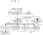
- Fig. 4 is a block diagram showing a system including such mechanism parts as a power spring, etc.
- IC integrated circuit
- an oscillation circuit 7 functioning by means of a quartz oscillator 10, a frequency dividing circuit 6, a cycle comparing circuit 8, a cycle detecting circuit 9, a load control circuit 5 and the like are driven by the storage power 108.
- the frequency of a signal oscillated by the operation of the quartz oscillator 10 is divided to given cycles via the oscillation circuit 7 and the frequency dividing circuit 6.
- the divided frequency signal is output to the cycle comparing circuit 8 as a reference cycle signal having a cycle of, for example, 1 second.
- the cycle detecting circuit 9 fetches an induced voltage 104 synchronized with the rotation cycle of the generator 3 and outputs a detected cycle signal 105 to the cycle comparing circuit 8.
- the cycle comparing circuit 8 compares each cycle of the reference cycle signal and the detected cycle signal, obtains a time difference between both signals and generates a cycle correction signal 106 for correcting the rotation cycle of the generator 3 and outputs it to the load control circuit 5 so as to eliminate the difference, that is, to synchronize the cycle of the generator 3 with the cycle of the reference cycle signal.
- the load control circuit 5 suitably selects a load resistor by switching a switch within the circuit and thereby changes the load current of the generator 3, that is, the amount of current 107 flowing to the coil of the generator 3, and governs the speed of the rotation cycle of the generator 3 by controlling the amount of an electromagnetic brake corresponding to the amount of current. Then, it synchronizes the rotation cycle of the generator 3 with a reference cycle signal generated by the IC and the quartz oscillator 10, to make the cycle constant. Then, by making constant the moving cycle of the hands 12 linked with the speed increasing gear train 2 for driving the generator 3, chronologically precise time is maintained.
- Fig. 3 shows connections among the circuits mentioned above.
- the following description relates to lasting time in such electronic control timepieces, that is, the time during which a power spring is gradually released from the state where it is wound to its limit and the hands can indicate accurate time.
- the lasting time is determined by the release angle ⁇ of the power spring where a relation between a power spring torque Tz and a minimum torque loss Thmin following the rotation of the generator becomes; Tz ⁇ Thmin x Z, wherein Z indicates a speed increasing ratio of the gear train from the power spring to the generator.
- the release angle ⁇ of the power spring per unit time is determined by; 2 ⁇ /( t x Z).
- a value ( ⁇ / ⁇ ) obtained by dividing the release angle ⁇ of the power spring by the angle ⁇ ⁇ becomes lasting time in the electronic control timepiece.
- the rotation cycle t of the generator must satisfy the following conditions:
- the generator of an electronic control timepiece is rotated under the above three conditions relating to the rotation cycle thereof.
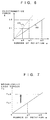
- Fig. 6 is a graph showing the relationship between the number of rotations ⁇ of a generator and an induced voltage E charged from the generator to the smoothing capacitor. As shown by a solid line (A) in Fig. 6, with the increase of the number of rotations of the generator, the induced voltage E increases. When the generator rotates at a number of its rotations ⁇ 1, the induced voltage E reaches its operational voltage El, that is, a voltage sufficient to secure the stable operation of the IC, including a quartz oscillation circuit.
- Fig. 7 is a graph showing the relationship between the number of rotations ⁇ of a generator and mechanical torque loss Ts.
- the mechanical torque loss increases with an increase in the number of rotations of a generator.
- the mechanical torque loss changes depending on the number of rotations of the generator and becomes Tsl when the number of rotations is ⁇ 1.
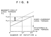
- Fig. 8 is a graph showing the relationship between the number of rotations of a generator and magnetic torque loss.
- the magnetic torque loss includes eddy-current torque loss and hysteresis torque loss. A sum of these two torque losses is the magnetic torque loss.
- the eddy-current torque loss increases with an increase in the number of rotations of the generator.
- the hysteresis torque loss is constant, having no relationship with the number of generator rotations, and is produced following consumption of energy made when a magnetic domain formed of a magnetic material on a magnetic path is inverted in accordance with the change of magnetic flux of a rotor magnet.
- the magnetic torque loss is Tul when the number of rotations of the generator is ⁇ 1.
- Thmin Tsl + Tul + Tg, where, Tg indicates electrical torque loss to be electrically consumed by the IC, including an oscillation circuit which is an electrical load on the generator, etc.
- the voltage of the smoothing capacitor is determined by a voltage induced by the generator.
- the operational voltage of the IC including the quartz oscillation circuit is high, it is necessary to increase the voltage induced by the generator.
- the characteristic shown by the broken line (B) in Fig. 6 is again obtained and thus the induced voltage may increase. In this case, however, the length or thickness of the coil increases. Also, in the case where the coil is made long, the length of the magnetic path is increased and thus magnetic torque loss increases.
- a control timepiece comprising:
- an electronic control timepiece having:
- the step-up circuit can be constructed in such a way that it is provided with a plurality of capacitors and a plurality of switching elements, and the plurality of switching elements being periodically switched so as to charge induced power produced by the generator by connecting the plurality of capacitors in parallel and discharge electricity to the smoothing capacitor by connecting the plurality of charged capacitors in series.
- step-up control circuit for controlling the step-up circuit, the step-up control circuit outputting a step-up control signal synchronized with a detected cycle signal in response to the detected cycle signal output from the cycle detecting circuit, and ON/OFF switching of the plurality of switching elements in the step-up circuit being controlled by means of the step-up control signal output from the step-up control circuit to thereby perform a step-up operation in synchronization with the detected cycle signal.
- the step-up control circuit prefferably be provided with a function for controlling the step-up multiplication ratio of the step-up circuit, outputting a step-up control signal synchronized with a detected cycle signal in response to the detected cycle signal output from the cycle detecting circuit, changing the step-up multiplication ratio of the step-up circuit in response to a cycle correction signal output from the cycle comparing circuit whereby the electric load on the generator is changed, and the rotation cycle of the generator coincides with a predetermined cycle corresponding to a reference cycle signal by controlling electrical torque loss from the generator, thereby providing the step-up circuit with the function of a variable load circuit.
- the step-up circuit may include a sub-capacitor serially connected to the generator, a terminal voltage of the sub-capacitor being superimposed on a voltage induced by the generator independently of the cycle of a detected cycle signal output from the cycle detecting circuit to boost a voltage charged to the smoothing capacitor.
- the step-up circuit prefferably be provided with a first step-up circuit including a plurality of capacitors and a plurality of switching elements, the plurality of switching elements being periodically switched so as to charge induce power induced by the generator by connecting the plurality of capacitors in parallel and discharging electricity of capacitors to the smoothing capacitor by connecting the plurality of capacitors in series, and a second step-up circuit including a sub-capacitor serially connected to the generator with its terminal voltage superimposed on a voltage induced by the generator independently of the cycle of a detected cycle signal output from the cycle detecting circuit for boosting a voltage charged to the smoothing capacitor.
- a first step-up circuit including a plurality of capacitors and a plurality of switching elements, the plurality of switching elements being periodically switched so as to charge induce power induced by the generator by connecting the plurality of capacitors in parallel and discharging electricity of capacitors to the smoothing capacitor by connecting the plurality of capacitors in series
- a second step-up circuit including a sub-capacitor
- variable load circuit includes a load control circuit having a switching element and a resistor, the switching element cyclically controls ON/OFF switching of connections between the resistor and the generator in response to a cycle correction signal output from the cycle comparing circuit and thereby changing the load on the generator.
- step-up magnifying ratio of the step-up circuit it is possible to change a load current on the generator and thereby to govern its speed with the number of rotations of the generator kept constant.
- step-up circuit By constituting the step-up circuit by a sub-capacitor and a diode, it is possible to obtain a step-up effect independently of the operation of the IC.
- Fig. 1 is a block diagram showing a circuit in the first embodiment while Fig. 2 is a block diagram showing the system of an electronic control timepiece including such mechanism parts as a power spring and the like and a step-up circuit 15 in the first embodiment.
- a power spring 1 stores mechanical energy 101 which powers a timepiece.
- This mechanical energy 101 moves hands 12 via a speed increasing gear train 2 and rotates a generator 3.
- a generator 3 By the rotation of the generator 3 an electromotive force is induced on both ends of a coil therein.
- Fig. 1 one end of the coil in the generator 3 is connected to a diode 21 and a load control circuit 5 provided in an IC 11 (the parts surrounded by a broken line in Fig. 1), and the other end is grounded.
- the diode 21 rectifies the flow of an AC electromotive force 102 induced by the generator 3.
- the electromotive force 102 whose flow is rectified, is supplied to the step-up circuit 15 in the IC 11.
- the step-up circuit 15 generates, for example, a step-up voltage 103 twice as high as the flow-rectified electromotive force 102 therefrom when necessary.
- the step-up voltage 103 is temporarily stored as storage power 108 in a smoothing capacitor 4 arranged in parallel with the step-up circuit 15.
- a step-up control circuit 16 generates a step-up control signal for controlling the boosting operation of the step-up circuit 15.
- the smoothing capacitor 4 allows the IC 11 to be continuously driven by constantly supplying the stored storage power 108 thereto.
- the IC 11 includes an oscillation circuit 7, a frequency dividing circuit 6, a cycle comparing circuit 8, a cycle detecting circuit 9, a load control circuit 5, a step-up circuit 15 and a step-up control circuit 16. One end of the respective circuits are grounded.
- the oscillation circuit 7 is electrically connected to a quartz oscillator 10 and outputs an oscillation clock signal to the frequency dividing circuit 6.
- the frequency dividing circuit 6 in turn generates a reference cycle signal of, for example, 1 second cycle by using the oscillation clock signal and outputs it to the cycle comparing circuit 8.
- the cycle detecting circuit 9 receives an induced voltage 104 from the generator 3, generates a detected cycle signal 105 synchronized with the rotation cycle of the generator 3 and outputs it to the cycle comparing circuit 8 and the step-up control circuit 16.
- the cycle comparing circuit 8 compares a cycle of the reference cycle signal generated by the frequency dividing circuit 6 and a cycle of the detected cycle signal generated by the cycle detecting circuit 9, generates a cycle correction signal 106 for eliminating a time difference between both signals and outputs it to the load control circuit 5.
- the step-up control circuit 16 generates a step-up control signal from the detected cycle signal and outputs it to the step-up circuit 15.
- the step-up circuit 15 in turn, based on the step-up control signal, carries out a boosting operation at the cycle of the induced voltage 104, that is, at a timing when it is synchronized with the rotation cycle of the generator 3.
- the load control circuit 5 changes a load current on the generator 3, that is, the amount of a current 107 flowing to a coil in the generator 3, by appropriately selecting a load resistor changing the switching elements within the internal circuit, controls the amount of an electromagnetic brake corresponding to the amount of a current 107 and thereby governs the speed of the rotation cycle of the generator 3.
- ON/OFF switching of the switching element provided on the load control circuit 5 is carried out corresponding to the cycle correction signal 106.
- the rotation cycle of the generator 3 is made coincident with a predetermined constant cycle. That is, in the case where a second hand is rotated accurately at 1 rpm, the rotation cycle of the generator 3 is made to correspond to a rotation speed increased or decreased by the amount of a speed increasing ratio Z from the second hand to the generator 3, the moving cycle of the hands 12 linked with the speed increasing gear train 2 driving the generator 3 is made constant and thereby time accuracy is secured.
- the load control circuit 5 is used to govern speeds of the generator 3 by means of controlling an electric load thereon. However, it may not be necessary when an electric load can be controlled by other means.
- the number of rotations of the generator can be made less than ⁇ 1. That is, by using the step-up circuit 15 the number of rotations of the generator can be reduced from ⁇ 1 to ⁇ 3 based on a characteristic indicated by broken line (B) in Fig. 6. Reduction in the number of rotations of the generator can be an effective means of making the lasting time of a power spring long.
- Fig. 9 is a circuit block diagram showing a step-up circuit capable of double boosting.
- the step-up circuit 15 includes switching elements 151, 152, 153 and 154 and step-up capacitors 155 and 156. ON/OFF switching of the switching elements 151, 152, 153 and 154 is controlled by step-up control signals S1 and S2 from the step-up control circuit 16.
- step-up control signals Sl and S2 are in high states (hereinafter termed "H") the switches are switched ON, and when the signals are in low states (hereinafter termed "L”) the switches are switched OFF.
- Figs. 10A and 10B respectively show connections among such electric elements as the generator 3, the diode 21, the smoothing capacitor 4 and the step-up capacitors 155 and 156 in the two states when the step-up circuit 15 carries out a boosting operation.
- the step-up circuit 15 repeats in turn a charged state where the step-up capacitors 155 and 156 are connected in parallel as shown in Fig. 10A and a discharged state where the step-up capacitors 155 and 156 are connected in series as shown in Fig. 10B.
- Fig. 11 shows timings for ON/OFF switching of the switching elements provided on the step-up circuit 15 and changes of the potential Vs of the step-up capacitors and potential Vc of the smoothing capacitor at the time of carrying out a boosting operation.
- a waveform E indicates a voltage induced by the generator 3
- the step-up control signal S1 indicates a timing for switching the switching elements 151 and 153 ON
- the step-up control signal S2 indicates a timing for switching the switching elements 152 and 154 ON.
- the ON/OFF states of the step-up control signals Sl and S2 are identified by observing whether the induced voltage E exceeds a reference voltage VTH or not. However, it is not necessary to limit the method of generating step-up control signals to that based on identification by means of a reference voltage.
- Table 1 briefly shows the operations of the step-up circuit 15.
- the step-up capacitors 155 and 156 are connected in parallel.
- the step-up capacitors 155 and 156 respectively form electric loops connected in parallel to the generator 3.
- the step-up capacitors 155 and 156 are connected in series.
- the step-up capacitors 155 and 156 thus connected in series form electric loops with the smoothing capacitor 4.
- the potential Vs of the two serially connected capacitors is.
- Vs (Vl + Vl).
- This potential (Vl + Vl) exceeds the potential Vc of the smoothing capacitor. This is because, as shown in Fig. 11, the storage power of the smoothing capacitor is always consumed by such electrical elements as ICs and the like and thus the potential Vc is gradually reduced from the initial period of a double boosting state.
- a current i3 flows between the smoothing capacitor 4 and the step-up circuit 15. Then, the potential Vc of the smoothing capacitor 4, as shown in Fig. 11, increases to a voltage whose potential is substantially equal to the potential Vs of the step-up capacitor. At this time, the potential Vl of the step-up capacitors 155 and 156 declines to Vc/2.
- step-up control signals S1 and S2 synchronized with the induced voltage E in the generator 3 and switching the switches of the step-up circuit 15 ON and OFF, it is possible to boost the potential of the smoothing capacitor 4 at any time.
- the smoothing capacitor 4 can store power having a sufficient potential to maintain the operation of the IC.
- the characteristic of the generator 3 can be substantially improved without expanding the space occupied by the generator.
- the induced voltage in the generator 3 is sufficiently high in the construction described above, it is possible to reduce the number of rotations of the generator by using the step-up circuit.
- lasting time can be substantially lengthened. Hence it is possible to provide a compact and thin electronic control timepiece having a long lasting time.
- the switching element 154 of the step-up circuit 15 shown in Fig. 9 can be replaced by a diode. That is, by providing the diode so as to prevent discharging of the storage power of the smoothing capacitor 4 to the side of the step-up capacitor it is possible to obtain the same advantage as ON/OFF switching of the switching element 154.
- step-up circuit 15 is provided inside the IC in the first embodiment, similar functions can be performed even if part or all of the circuit elements are provided outside the IC.
- the step-up magnifying ratio of the step-up circuit 15 variable, the amount of current flowing to an electrically closed loop formed by the generator 3 and the step-up circuit can be adjusted, the size of an electromagnetic brake generated in the generator 3 changed and, thereby, the speed of the rotation cycle of the generator 3 kept constant.
- This control of the number of rotations is based on the principle that if an electromotive force induced by the generator and power expended for stepping up including power consumed by the IC are equalized, the rotation cycle of the generator 3 can be made constant. In this construction, it is unnecessary to use a load control circuit as a means of governing the speed of the generator 3.
- the abscissa indicates a voltage applied to the IC while the ordinate indicates power consumed by the IC per unit time.
- the applied voltage exceeds a voltage V0 for starting an IC operation, the IC starts its operation and consumes power. Then, as the applied voltage increases, power consumption also increases.
- the step-up circuit 15 boosts the potential of the smoothing capacitor 4 and power flowing to the step-up circuit also changes in proportion to power consumed by the IC, the amount of current flowing between the generator and the step-up circuit changes. Further, since the rotation cycle of the generator depends on the amount of current flowing thereto, it is possible to control the rotation cycle thereof by changing the step-up magnifying ratio of the step-up circuit.
- an electromotive force 102 generated at both ends of the coil in the generator 3 is applied to the step-up circuit 15.
- the step-up circuit 15 executes a boosting operation in response to a step-up control signal generated by the step-up control circuit 16 and thereby boosts the voltage of the electromotive force to a predetermined multiplied ratio.
- the smoothing capacitor 4 is charged with a step-up voltage 103 from the step-up circuit 15 and consequently the electromotive force 102 is temporarily stored in the smoothing capacitor 4 as storage power.
- the smoothing capacitor 4 is electrically connected to the IC 11 and it is possible to continuously drive the IC 11 by constantly supplying the storage power in the smoothing capacitor 4 thereto.
- the signal oscillated by the operation of the quartz oscillator 10 is divided into predetermined cycles from the oscillation circuit 7 via the frequency dividing circuit 6.
- the frequency-divided signal is output to the cycle comparing circuit 8 as a reference cycle signal of, for example, 1 second period.
- the cycle detecting circuit 9 fetches an induced voltage 104 from the generator 3, generates a detected cycle signal 105 synchronized with the rotation cycle of the generator 3 and outputs it to the cycle comparing circuit 8 and the step-up control circuit 16.
- the cycle comparing circuit 8 compares each cycle of a reference cycle signal generated by the frequency dividing circuit 6 and a detected cycle signal generated by the cycle detecting circuit 9, generates a cycle correction signal 106 for eliminating a time difference between both signals, and outputs it to the step-up control circuit 16.
- the step-up control circuit 16 generates a step-up control signal based on the cycle correction signal and the detected cycle signal and outputs it to the step-up circuit 15.
- the step-up circuit 15 changes connections among a plurality of capacitors provided in parallel or in series thereon by switching the switches of the circuit. ON/OFF switching of the switching elements on the step-up circuit 15 is carried out in accordance with the step-up control signal generated by the step-up control circuit 16. Then, by appropriately changing a step-up multiplication ratio a load current on the generator 3, that is, the current amount 107 flowing from the coil in the generator 3 to the step-up circuit 15, is changed, the amount of an electromagnetic brake corresponding to the current amount 107 is controlled, and thereby the speed of the number of rotations of the generator 3 is governed.
- transmission of mechanical energy from the power spring 1 to the generator 3 and transmission of electric energy from the smoothing capacitor 4 to the IC 11 and the quartz oscillator 10 are similar to those in the first embodiment described with reference to Fig. 2.
- Fig. 15 is a circuit block diagram showing a step-up circuit 15, a generator 3, a smoothing capacitor 4, a cycle detecting circuit 9 and a step-up control circuit 16, which together allow double step-up.
- the step-up circuit 15 is provided with switching elements 151, 152, 153 and 154 and step-up capacitors 155 and 156. ON/OFF switching of the switching elements 151, 152, 153 and 154 is controlled by step-up control signals S1 and S2 from the step-up control circuit 16.
- the step-up control signals S1 and S2 are H, the switches are switched ON, and are switched OFF when the step-up control signals are L.
- the step-up control circuit 16 is connected to the IC 11 and the cycle detecting circuit 9, generates a step-up control signal based on a cycle correction signal and a detected cycle signal and outputs it to the step-up circuit 15.
- Fig. 16 the abscissa indicates the release angle of a power spring corresponding to lasting time while the ordinate indicates power spring torque Tz.
- the state where the power spring is wound to its limit is a release angle ⁇ 0 and power spring torque at this time is Tzmax.
- Power spring torque is Tzl when the power spring release angle changes from ⁇ 0 to ⁇ 1 (section A).
- Power spring torque is Tz2 when the power spring release angle changes from ⁇ 1 to ⁇ 2 (section B).
- Power spring torque is Tzmin when the power spring release angle changes from ⁇ 1 to ⁇ 3 (section C).
- electrical torque loss Tg is Tg1 at the time of no step-up (one time step-up), Tg2 at the time of double step-up (two times step-up), Tg3 at the time of triple step-up (three times step-up) and Tg4 at the time of quadruple step-up (four times step-up).
- Power spring torques Tzl, Tz2 and Tzmin and torque loss equivalent to electrically consumed torque Tg3, Tg2 and Tg1 must be balanced.
- the number of rotations of the generator can be kept constant by alternately changing quadruple and triple step-ups. Also, since Tz is between Tg3 and Tg2 in the section B, the number of rotations of the generator can be kept constant by alternately changing triple and double step-ups. Since Tz is between Tg2 and Tgl in the section C, the number of rotations of the generator can be kept constant by alternately changing double and single (no step-up) step-ups.
- the structure according to the present embodiment is made such that the step-up operation of an induced voltage in the generator can be executed independently of the operation of the IC.
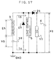
- a step-up circuit shown in Fig. 17 includes a sub-capacitor 18 and a diode 17.
- the sub-capacitor 18 is arranged in series with a generator 3.
- An electrically closed loop is formed by the generator 3, the sub-capacitor 18 and the diode 17.
- the cathode terminal of the diode 17 is connected to the anode terminal of a diode 21 and one terminal of the generator 3.
- the anode terminal of the diode 17 is connected to one terminal of the sub-capacitor 18.
- step-up principle of the step-up circuit is described in the following.
- An AC electromotive force is generated in the generator 3. Its current flows in an ia or ib direction.
- the current ia is made to flow when it exceeds a potential Vb stored in the sub-capacitor 18 and an electric charge is stored therein, increasing the potential thereof. At this time, the current is made to flow to the electrically closed loop formed by the generator 3, the sub-capacitor 18 and the diode 17.
- Fig. 18 shows a waveform obtained by boosting the induced voltage E of the generator 3 by a voltage Vb held in the sub-capacitor 18.
- a solid line in Fig. 8 indicates a voltage obtained as a result of boosting (E+Vb), while a broken line indicates the result of measuring the induced voltage E of the generator.
- step-up circuit utilizing the fact that an induced voltage induced by the generator has an alternate characteristic irrespective of the existence of the electrical operation of the IC 11, it is possible to boost the potential of power charged to the smoothing capacitor.
- an advantage such as when the induced voltage of the generator is increased can be obtained. In this way, the number of rotations of the generator can be reduced and thereby a compact and thin electronic control timepiece having a long lasting time can be provided.
- the fourth embodiment of the present invention is shown in Fig. 19.
- the fourth embodiment is related to another structure for carrying out a step-up operation of the induced voltage of the generator independently of the operation of the IC.
- Fig. 19 which is a circuit block diagram, a smoothing capacitor 4 and a sub-capacitor 18 are arranged in series with respect to an IC 11.
- the basic operation of this step-up capacitor is the same as that in the third embodiment and the advantage obtained is also the same as that in the third embodiment.
- the fifth embodiment of the present invention is shown in Fig. 20.
- the step-up multiplication ratio is further increased by combining a step-up circuit 15 for carrying out electrical boosting and a step-up circuit by a sub-capacitor 18 operated independently of the operation of the IC.
- the basic step-up operation of the fifth embodiment is the same as in the first and third embodiments.
- the advantage obtained is that obtained by combining the advantages of those in the first and third embodiments.
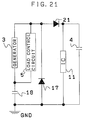
- the sixth embodiment of the present invention is shown in Fig. 21.
- a load control circuit 5 and a generator 3 are arranged in parallel with respect to a sub-capacitor 18.
- the basic operation of this step-up circuit is the same as that in the third embodiment. Since it is possible to obtain the same advantage as that in the third embodiment, prevent consumption of storage power stored in the sub-capacitor 18 by the load control circuit 5, and maintain the voltage of the sub-capacitor independently of the operation of the load control circuit 5, a step-up voltage can be maintained more stably.
- the seventh embodiment of the present invention is shown in Fig. 22.
- in the seventh embodiment 7 it is possible to further increase a step-up multiplication ratio by combining a step-up circuit 15 for carrying out electrical boosting as shown in the first embodiment and a step-up circuit by a sub-capacitor 18 as shown in the sixth embodiment.
- the basic operation of the step-up circuit in the seventh embodiment is the same as those in the first and sixth embodiments.
- the advantage obtained is that obtained by combining the advantages of the first and sixth embodiments.
- the eighth embodiment of the present invention is shown in Fig. 23.
- the step-up multiplication ratio is further increased.
- the basic step-up operation and the speed governing operation in the eighth embodiment are the same as those in the second and third embodiments.
- the advantage obtained is that obtained by combining the advantages of the second and third embodiments.
- the ninth embodiment of the present invention is shown in Fig. 24.
- a step-up multiplication ratio is further increased.
- a load control circuit 5 is arranged in parallel with a generator 3 and normally, as in the case of the second embodiment, the speed of the rotation cycle of the generator is governed by the step-up circuit 15.
- control of the number of rotations of the generator is executed by the load control circuit 5.
- a cycle detecting circuit 9 detects the acceleration of the generator and outputs its detected cycle signal to a step-up control circuit 16.
- the step-up control circuit 16 in turn outputs a signal for increasing a step-up multiplication ratio to the step-up circuit 15 based on the detected cycle signal.
- a signal is output from the step-up control circuit 16 to the load control circuit 5 and thereby operation thereof is started.
- a current flows to the load control circuit 5
- an electromagnetic brake is applied to the generator, and the rotation cycle of the generator is made to coincide with the predetermined cycle.
- the load control circuit 5 executes control of the number of rotations, replacing the step-up circuit.
- the basic step-up operation and speed governing operation in the present embodiment are the same as those in the second and third embodiments.
- the advantage obtained is that obtained by combining the advantages of the second and sixth embodiments.
- the characteristic of the generator 3 can be substantially improved without expanding its space. Also, in the case where the induced voltage of the generator 3 is sufficiently high, it is possible to reduce the number of rotations of the generator by using the step-up circuit. This means that lasting time can be substantially lengthened without expanding the space for the power spring. Consequently, a compact and thin electronic control timepiece having a long lasting time can be provided.
- the number of rotations of the generator can be controlled by appropriately changing the step-up multiplication ratios and the amount of power consumed by the IC, it is not necessary to use a special load control circuit. Also, since lasting time can be substantially lengthened without expanding the spaces required for the generator 3 and the power spring, a compact and thin electronic control timepiece can be provided.
- the step-up circuit including a sub-capacitor and a diode can be made to boost the potential of power charging to the smoothing capacitor irrespective of the existence of the electrical operation of the IC 11.
- the same advantage is obtained as when the induced voltage of the generator increases. Since the number of rotations of the generator can be reduced in this way, it is possible to provide a compact and thin electronic control timepiece having a long lasting time.
- the induced voltage of the generator 3 does not reach the operational voltage of the IC, a potential sufficient to maintain the operation of the IC by means of the step-up circuit can be ensured and thus it is possible to prevent failure to detect the number of rotations of the generator 3 and thereby to detect the number of rotations at any time. Consequently, the speed of the rotation of the generator can be further accurately governed and thus chronological precision of a timepiece can be improved.
Landscapes
- Engineering & Computer Science (AREA)
- Power Engineering (AREA)
- Physics & Mathematics (AREA)
- General Physics & Mathematics (AREA)
- Electromechanical Clocks (AREA)
- Connection Of Motors, Electrical Generators, Mechanical Devices, And The Like (AREA)
- Dc-Dc Converters (AREA)
Applications Claiming Priority (5)
| Application Number | Priority Date | Filing Date | Title |
|---|---|---|---|
| JP18261794 | 1994-08-03 | ||
| JP18261794 | 1994-08-03 | ||
| JP15654695 | 1995-06-22 | ||
| JP15654695A JP3174245B2 (ja) | 1994-08-03 | 1995-06-22 | 電子制御時計 |
| EP95305448A EP0695978B1 (fr) | 1994-08-03 | 1995-08-03 | Montre de contrôle électronique |
Related Parent Applications (1)
| Application Number | Title | Priority Date | Filing Date |
|---|---|---|---|
| EP95305448A Division EP0695978B1 (fr) | 1994-08-03 | 1995-08-03 | Montre de contrôle électronique |
Publications (3)
| Publication Number | Publication Date |
|---|---|
| EP0982638A1 true EP0982638A1 (fr) | 2000-03-01 |
| EP0982638B1 EP0982638B1 (fr) | 2003-05-02 |
| EP0982638B2 EP0982638B2 (fr) | 2006-09-13 |
Family
ID=26484258
Family Applications (2)
| Application Number | Title | Priority Date | Filing Date |
|---|---|---|---|
| EP95305448A Expired - Lifetime EP0695978B1 (fr) | 1994-08-03 | 1995-08-03 | Montre de contrôle électronique |
| EP99203757A Expired - Lifetime EP0982638B2 (fr) | 1994-08-03 | 1995-08-03 | Montre de contrôle électronique |
Family Applications Before (1)
| Application Number | Title | Priority Date | Filing Date |
|---|---|---|---|
| EP95305448A Expired - Lifetime EP0695978B1 (fr) | 1994-08-03 | 1995-08-03 | Montre de contrôle électronique |
Country Status (5)
| Country | Link |
|---|---|
| US (1) | US5615178A (fr) |
| EP (2) | EP0695978B1 (fr) |
| JP (1) | JP3174245B2 (fr) |
| DE (2) | DE69530623T3 (fr) |
| HK (2) | HK1014773A1 (fr) |
Cited By (1)
| Publication number | Priority date | Publication date | Assignee | Title |
|---|---|---|---|---|
| GB2432432A (en) * | 2005-11-16 | 2007-05-23 | Polymeters Response Internat L | Correcting timekeeper with oscillating signal |
Families Citing this family (24)
| Publication number | Priority date | Publication date | Assignee | Title |
|---|---|---|---|---|
| DK0848842T3 (da) | 1996-06-26 | 1999-11-08 | Konrad Schafroth | Urværk |
| CH690523A5 (fr) * | 1996-12-09 | 2000-09-29 | Asulab Sa | Pièce d'horlogerie comportant une génératrice d'énergie électrique. |
| EP0848306B1 (fr) * | 1996-12-10 | 2000-08-02 | Asulab S.A. | Pièce d'horlogerie comportant une génératrice d'énergie électrique |
| CH689469A5 (fr) * | 1996-12-18 | 1999-04-30 | Patek Philippe Sa | Convertisseur d'énergie mécano-électrique et pièce d'horlogerie comportant un tel convertisseur d'énergie. |
| ES2145416T3 (es) * | 1996-12-23 | 2000-07-01 | Ronda Ag | Microgenerador, modulo y mecanismo de relojeria que contiene un microgenerador de este tipo. |
| JP3572473B2 (ja) | 1997-01-30 | 2004-10-06 | 株式会社ルネサステクノロジ | 液晶表示制御装置 |
| US6034492A (en) * | 1997-04-30 | 2000-03-07 | Nec Corporation | Motor-generator |
| JP3094954B2 (ja) * | 1997-06-19 | 2000-10-03 | 日本電気株式会社 | 電源装置 |
| EP0905587B1 (fr) * | 1997-09-26 | 2002-11-13 | Seiko Epson Corporation | Montre mécanique réglée électriquement |
| US6795378B2 (en) | 1997-09-30 | 2004-09-21 | Seiko Epson Corporation | Electronic device, electronically controlled mechanical timepiece, and control method therefor |
| JP3006593B2 (ja) | 1997-09-30 | 2000-02-07 | セイコーエプソン株式会社 | 電子制御式機械時計およびその制御方法 |
| US6041021A (en) | 1997-09-30 | 2000-03-21 | Seiko Epson Corporation | Electronically controlled mechanical timepiece and control method therefor |
| US6477116B1 (en) | 1997-09-30 | 2002-11-05 | Seiko Epson Corporation | Rotation controller and rotation control method |
| US6314059B1 (en) * | 1997-09-30 | 2001-11-06 | Seiko Epson Corporation | Electronically controlled, mechanical timepiece and control method for the same |
| DE69928496T8 (de) * | 1998-09-17 | 2006-09-21 | Seiko Epson Corp. | Stromversorgungsgerät, stromversorgungsverfahren, tragbares elektronisches gerät und elektronische uhr |
| EP1055981B1 (fr) * | 1998-11-17 | 2008-12-31 | Seiko Epson Corporation | Montre mecanique a commande electronique et procede permettant d'eviter les surcharges |
| US6633511B1 (en) | 1998-11-17 | 2003-10-14 | Seiko Epson Corporation | Electronic controlling type mechanical timepiece |
| DE69940303D1 (de) | 1998-11-19 | 2009-03-05 | Seiko Epson Corp | Elektrisch kontrollierte mechanische uhr und bremsverfahren |
| CN100399217C (zh) | 1999-03-03 | 2008-07-02 | 精工爱普生株式会社 | 电子设备及其控制方法 |
| WO2002004836A2 (fr) * | 2000-07-11 | 2002-01-17 | Seiko Epson Corporation | Ressort, mecanisme d'entrainement, dispositif et piece d'horlogerie integrant ce ressort |
| JP4618749B2 (ja) * | 2000-07-17 | 2011-01-26 | リコーエレメックス株式会社 | 時計部を備える小型機器用充電装置 |
| JP2002281684A (ja) * | 2001-01-11 | 2002-09-27 | Seiko Epson Corp | 弱電用発電装置 |
| JP4007932B2 (ja) * | 2002-03-19 | 2007-11-14 | 株式会社タキオン | マイクロ波送電法、マイクロ波受電装置及びidタグシステム |
| JP4459812B2 (ja) * | 2002-09-24 | 2010-04-28 | シチズンホールディングス株式会社 | 電子時計 |
Citations (12)
| Publication number | Priority date | Publication date | Assignee | Title |
|---|---|---|---|---|
| FR2339280A1 (fr) * | 1976-01-26 | 1977-08-19 | Fairchild Camera Instr Co | Circuit multiplieur de tension |
| CH597636B5 (fr) | 1972-11-21 | 1978-04-14 | Ebauches Sa | |
| US4141064A (en) | 1976-11-29 | 1979-02-20 | Kabushiki Kaisha Suwa Seikosha | Booster circuit |
| GB2158274A (en) | 1984-03-29 | 1985-11-06 | Suwa Seikosha Kk | Electronic timepiece |
| EP0239820A1 (fr) * | 1986-03-26 | 1987-10-07 | Asulab S.A. | Convertisseur d'énergie mécanique en énergie électrique |
| EP0241219A2 (fr) | 1986-04-08 | 1987-10-14 | Seiko Instruments Inc. | Pièce d'horlogerie électronique |
| US4730287A (en) * | 1985-04-10 | 1988-03-08 | Seiko Epson Corporation | Power supply for electronic timpiece |
| US4799003A (en) | 1987-05-28 | 1989-01-17 | Tu Xuan M | Mechanical-to-electrical energy converter |
| EP0326312A2 (fr) | 1988-01-25 | 1989-08-02 | Seiko Epson Corporation | Montre bracelet électronique |
| EP0326313A2 (fr) * | 1988-01-25 | 1989-08-02 | Seiko Epson Corporation | Montre bracelet |
| EP0467667A2 (fr) | 1990-07-18 | 1992-01-22 | Seiko Epson Corporation | Circuit d'alimentation pour appareillages électroniques |
| US5668414A (en) * | 1994-07-04 | 1997-09-16 | Seiko Epson Corporation | Spring driven electricity generator with a control circuit to regulate the release of energy in the spring |
Family Cites Families (4)
| Publication number | Priority date | Publication date | Assignee | Title |
|---|---|---|---|---|
| JPS5232374A (en) * | 1975-09-08 | 1977-03-11 | Citizen Watch Co Ltd | Electronic watch |
| JPS59116078A (ja) | 1982-12-23 | 1984-07-04 | Seiko Epson Corp | 時計 |
| JPS59135388A (ja) | 1983-01-25 | 1984-08-03 | Seiko Epson Corp | 時計 |
| DE59107118D1 (de) * | 1990-10-22 | 1996-02-01 | Gigandet Charles Sa | Armbanduhr |
-
1995
- 1995-06-22 JP JP15654695A patent/JP3174245B2/ja not_active Expired - Lifetime
- 1995-08-03 EP EP95305448A patent/EP0695978B1/fr not_active Expired - Lifetime
- 1995-08-03 EP EP99203757A patent/EP0982638B2/fr not_active Expired - Lifetime
- 1995-08-03 DE DE69530623T patent/DE69530623T3/de not_active Expired - Lifetime
- 1995-08-03 DE DE69524497T patent/DE69524497T2/de not_active Expired - Lifetime
-
1996
- 1996-01-29 US US08/591,987 patent/US5615178A/en not_active Expired - Lifetime
-
1998
- 1998-12-28 HK HK98115943A patent/HK1014773A1/xx not_active IP Right Cessation
-
2000
- 2000-08-21 HK HK00105245A patent/HK1026032A1/xx not_active IP Right Cessation
Patent Citations (13)
| Publication number | Priority date | Publication date | Assignee | Title |
|---|---|---|---|---|
| CH597636B5 (fr) | 1972-11-21 | 1978-04-14 | Ebauches Sa | |
| GB1552669A (en) | 1976-01-26 | 1979-09-19 | Fairchild Camera Instr Co | Voltage multiplier circuit |
| FR2339280A1 (fr) * | 1976-01-26 | 1977-08-19 | Fairchild Camera Instr Co | Circuit multiplieur de tension |
| US4141064A (en) | 1976-11-29 | 1979-02-20 | Kabushiki Kaisha Suwa Seikosha | Booster circuit |
| GB2158274A (en) | 1984-03-29 | 1985-11-06 | Suwa Seikosha Kk | Electronic timepiece |
| US4730287A (en) * | 1985-04-10 | 1988-03-08 | Seiko Epson Corporation | Power supply for electronic timpiece |
| EP0239820A1 (fr) * | 1986-03-26 | 1987-10-07 | Asulab S.A. | Convertisseur d'énergie mécanique en énergie électrique |
| EP0241219A2 (fr) | 1986-04-08 | 1987-10-14 | Seiko Instruments Inc. | Pièce d'horlogerie électronique |
| US4799003A (en) | 1987-05-28 | 1989-01-17 | Tu Xuan M | Mechanical-to-electrical energy converter |
| EP0326312A2 (fr) | 1988-01-25 | 1989-08-02 | Seiko Epson Corporation | Montre bracelet électronique |
| EP0326313A2 (fr) * | 1988-01-25 | 1989-08-02 | Seiko Epson Corporation | Montre bracelet |
| EP0467667A2 (fr) | 1990-07-18 | 1992-01-22 | Seiko Epson Corporation | Circuit d'alimentation pour appareillages électroniques |
| US5668414A (en) * | 1994-07-04 | 1997-09-16 | Seiko Epson Corporation | Spring driven electricity generator with a control circuit to regulate the release of energy in the spring |
Non-Patent Citations (12)
| Title |
|---|
| "1981 HANDBOOK", 1981, THE AMERICAN RADIO RELAY LEAGUE, pages: 5/8 - 5/9, XP002909143 |
| "DIE PLATTFORM FUERS NETZ THE NETWORK SOLUTION LA PLATEFORME DE RESEAU", ANNOUNCEMENT KNUERR, XX, XX, 1 January 1900 (1900-01-01), XX, pages 01 - 04, XP002940597 |
| "MECHANISCHE BAUWEISEN FUER DIE ELEKTRONIK ENCLOSURES FOR ELECTRONICS CONSTRUCTIONS MECANIQUES POUR L'ELECTRONIQUE", ANNOUNCEMENT KNUERR, XX, XX, 1 January 1900 (1900-01-01), XX, pages 01 - 05, XP002940598 |
| BITTERLICH, W. UND HOMMEL, R.: "Einfuehrung in die Elektronik", 1967, SPEINGER-VERLAG, WIEN, AT, pages: 552 - 556, XP002940503 |
| CHATELAIN J-D. ET DESSOULAVY R.: "TRAITE D'ELECTRICITE", vol. VIII, part 8.5 1982, EDITIONS GEORGI, ISBN: 2-604-00002-4, article "AUTRES TYPES DE REDRESSEURS", pages: 420 - 423, XP002909142 |
| CONRAD, WALTER: "Elektronik - Funktechnik", 1982, VEB BIBLIOGRAPHISCHES INSTITUT, LEIPZIG, DE, pages: 161 - 163, XP002940508 |
| FUNKE, R. UND LIEBSCHER, S.: "Grundschaltungen der Elektronik, Lehrbuch fuer die Berufsbildung", 1983, VEB VERLAG TECHNIK, BERLIN, DE, article "Stromversorgungsschaltungen", pages: 9 - 14, XP002940505 |
| HAYAKAWA, M.: "A Study of the New Energy System for Quartz Watches (II) - The Effective Circuit for the System", ACTES DES CONGRES EUROPEEN DE CHRONOMETRIE, 23 September 1988 (1988-09-23) - 24 September 1988 (1988-09-24), GENEVE, CH, pages 81 - 85, XP000035001 |
| LINDNER, H. ET AL.: "Elektrotechnik - Elektronik", vol. 2, 1983, VEB FACHBUCHVERLAG, LEIPZIG, DE, pages: 290 - 293, XP002943506 |
| ROST, ALBRECHT: "Grundlagen der Elektronik", 1986, AKADEMIE-VERLAG, BERLIN, DE, pages: 161 - 163, XP002943504 |
| RUMPF, KARL-HEINZ: "Bauelemente der Elektronik", vol. 12, 1985, VEB VERLAG TECHNIK, BERLIN, DE, pages: 163 - 167, XP002940507 |
| WAHL, ROLF: "Elektronik fuer Elektromechaniker, Ein Handbuch", 1982, VEB VERLAG TECHNIK, BERLIN, DE, pages: 272 - 275, XP002940502 |
Cited By (2)
| Publication number | Priority date | Publication date | Assignee | Title |
|---|---|---|---|---|
| GB2432432A (en) * | 2005-11-16 | 2007-05-23 | Polymeters Response Internat L | Correcting timekeeper with oscillating signal |
| GB2432432B (en) * | 2005-11-16 | 2009-04-15 | Polymeters Response Internat L | Timekeeping apparatus |
Also Published As
| Publication number | Publication date |
|---|---|
| EP0982638B1 (fr) | 2003-05-02 |
| JP3174245B2 (ja) | 2001-06-11 |
| EP0982638B2 (fr) | 2006-09-13 |
| DE69524497D1 (de) | 2002-01-24 |
| US5615178A (en) | 1997-03-25 |
| DE69530623D1 (de) | 2003-06-05 |
| HK1026032A1 (en) | 2000-12-01 |
| DE69530623T2 (de) | 2003-10-16 |
| DE69524497T2 (de) | 2002-05-16 |
| HK1014773A1 (en) | 1999-09-30 |
| EP0695978A1 (fr) | 1996-02-07 |
| JPH08101284A (ja) | 1996-04-16 |
| DE69530623T3 (de) | 2007-05-10 |
| EP0695978B1 (fr) | 2001-12-12 |
Similar Documents
| Publication | Publication Date | Title |
|---|---|---|
| EP0695978B1 (fr) | Montre de contrôle électronique | |
| US11687041B2 (en) | Timepiece comprising a mechanical oscillator wherein the medium frequency is synchronised on that of a reference electronic oscillator | |
| WO1998041906A1 (fr) | Montre electronique a generateur | |
| EP0942341B1 (fr) | Horloge mecanique a commande electronique et son procede de commande | |
| JP2020052047A (ja) | 機械式発振器の平均周波数を制御するための電子デバイスと関連付けられた機械式発振器を備える計時器アセンブリ | |
| US11422510B2 (en) | Timepiece comprising a mechanical oscillator associated with a regulation system | |
| US11846915B2 (en) | Timepiece comprising a mechanical oscillator associated with a regulation system | |
| JP2000329863A (ja) | 電子制御時計 | |
| JPH10177079A (ja) | 発電機を備えた時計 | |
| US11868092B2 (en) | Timepiece comprising a mechanical oscillator associated with a regulation system | |
| JP3767388B2 (ja) | 圧電調速機およびこの圧電調速機を用いた電子機器 | |
| JP3120204B2 (ja) | 電子制御時計 | |
| JP3654056B2 (ja) | 電子時計及び電子時計の制御方法 | |
| JP3598761B2 (ja) | 電子制御型機械式時計 | |
| JP2022090621A (ja) | 発電機を備える計時器用ムーブメント及びこの発電機の回転周波数を調整するための回路 | |
| JP3601258B2 (ja) | 電子制御式機械時計 | |
| JP3113999B2 (ja) | 電子制御時計 | |
| JPH0694850A (ja) | 発電装置付電子時計 | |
| JPH11166980A (ja) | 電子制御式機械時計およびその制御方法 | |
| SU1295486A1 (ru) | Компенсатор реактивной мощности | |
| JPH1123736A (ja) | 電子制御式機械時計 | |
| JP2000121756A (ja) | 電子制御式機械時計 | |
| JP2004301714A (ja) | 電子制御式機械時計および電子制御式機械時計の制御方法 | |
| JP2003107175A (ja) | 電子機器、電子機器の制御方法、電子機器を制御するプログラムが記録された記録媒体および電子機器の制御用プログラム | |
| JP2000121761A (ja) | 発電調速装置及びこれを使用したメトロノーム |
Legal Events
| Date | Code | Title | Description |
|---|---|---|---|
| PUAI | Public reference made under article 153(3) epc to a published international application that has entered the european phase |
Free format text: ORIGINAL CODE: 0009012 |
|
| 17P | Request for examination filed |
Effective date: 19991130 |
|
| AC | Divisional application: reference to earlier application |
Ref document number: 695978 Country of ref document: EP |
|
| AK | Designated contracting states |
Kind code of ref document: A1 Designated state(s): CH DE FR GB LI NL |
|
| AX | Request for extension of the european patent |
Free format text: LT;LV;SI |
|
| AKX | Designation fees paid |
Free format text: CH DE FR GB LI NL |
|
| TPAD | Observations filed by third parties |
Free format text: ORIGINAL CODE: EPIDOS TIPA |
|
| 17Q | First examination report despatched |
Effective date: 20010510 |
|
| GRAG | Despatch of communication of intention to grant |
Free format text: ORIGINAL CODE: EPIDOS AGRA |
|
| TPAD | Observations filed by third parties |
Free format text: ORIGINAL CODE: EPIDOS TIPA |
|
| GRAG | Despatch of communication of intention to grant |
Free format text: ORIGINAL CODE: EPIDOS AGRA |
|
| GRAH | Despatch of communication of intention to grant a patent |
Free format text: ORIGINAL CODE: EPIDOS IGRA |
|
| GRAH | Despatch of communication of intention to grant a patent |
Free format text: ORIGINAL CODE: EPIDOS IGRA |
|
| GRAA | (expected) grant |
Free format text: ORIGINAL CODE: 0009210 |
|
| AC | Divisional application: reference to earlier application |
Ref document number: 0695978 Country of ref document: EP Kind code of ref document: P |
|
| AK | Designated contracting states |
Designated state(s): CH DE FR GB LI NL |
|
| REG | Reference to a national code |
Ref country code: GB Ref legal event code: FG4D |
|
| REG | Reference to a national code |
Ref country code: CH Ref legal event code: EP |
|
| REF | Corresponds to: |
Ref document number: 69530623 Country of ref document: DE Date of ref document: 20030605 Kind code of ref document: P |
|
| REG | Reference to a national code |
Ref country code: CH Ref legal event code: NV Representative=s name: PATENTANWAELTE SCHAAD, BALASS, MENZL & PARTNER AG |
|
| ET | Fr: translation filed | ||
| PLBI | Opposition filed |
Free format text: ORIGINAL CODE: 0009260 |
|
| PLBQ | Unpublished change to opponent data |
Free format text: ORIGINAL CODE: EPIDOS OPPO |
|
| PLAX | Notice of opposition and request to file observation + time limit sent |
Free format text: ORIGINAL CODE: EPIDOSNOBS2 |
|
| 26 | Opposition filed |
Opponent name: DIETER EBBINGHAUS Effective date: 20040130 |
|
| NLR1 | Nl: opposition has been filed with the epo |
Opponent name: DIETER EBBINGHAUS |
|
| PLBB | Reply of patent proprietor to notice(s) of opposition received |
Free format text: ORIGINAL CODE: EPIDOSNOBS3 |
|
| PUAH | Patent maintained in amended form |
Free format text: ORIGINAL CODE: 0009272 |
|
| STAA | Information on the status of an ep patent application or granted ep patent |
Free format text: STATUS: PATENT MAINTAINED AS AMENDED |
|
| 27A | Patent maintained in amended form |
Effective date: 20060913 |
|
| AK | Designated contracting states |
Kind code of ref document: B2 Designated state(s): CH DE FR GB LI NL |
|
| REG | Reference to a national code |
Ref country code: CH Ref legal event code: AEN Free format text: MAINTIEN DU BREVET DONT L'ETENDUE A ETE MODIFIEE |
|
| NLR2 | Nl: decision of opposition |
Effective date: 20060913 |
|
| NLR3 | Nl: receipt of modified translations in the netherlands language after an opposition procedure | ||
| ET3 | Fr: translation filed ** decision concerning opposition | ||
| REG | Reference to a national code |
Ref country code: HK Ref legal event code: AM43 Ref document number: 1026032 Country of ref document: HK |
|
| PGFP | Annual fee paid to national office [announced via postgrant information from national office to epo] |
Ref country code: DE Payment date: 20140730 Year of fee payment: 20 Ref country code: NL Payment date: 20140710 Year of fee payment: 20 Ref country code: CH Payment date: 20140812 Year of fee payment: 20 |
|
| PGFP | Annual fee paid to national office [announced via postgrant information from national office to epo] |
Ref country code: FR Payment date: 20140808 Year of fee payment: 20 Ref country code: GB Payment date: 20140730 Year of fee payment: 20 |
|
| REG | Reference to a national code |
Ref country code: DE Ref legal event code: R071 Ref document number: 69530623 Country of ref document: DE |
|
| REG | Reference to a national code |
Ref country code: NL Ref legal event code: V4 Effective date: 20150803 |
|
| REG | Reference to a national code |
Ref country code: CH Ref legal event code: PL |
|
| REG | Reference to a national code |
Ref country code: GB Ref legal event code: PE20 Expiry date: 20150802 |
|
| PG25 | Lapsed in a contracting state [announced via postgrant information from national office to epo] |
Ref country code: GB Free format text: LAPSE BECAUSE OF EXPIRATION OF PROTECTION Effective date: 20150802 |