EP0980839A2 - Zuführvorrichtung - Google Patents
Zuführvorrichtung Download PDFInfo
- Publication number
- EP0980839A2 EP0980839A2 EP99114294A EP99114294A EP0980839A2 EP 0980839 A2 EP0980839 A2 EP 0980839A2 EP 99114294 A EP99114294 A EP 99114294A EP 99114294 A EP99114294 A EP 99114294A EP 0980839 A2 EP0980839 A2 EP 0980839A2
- Authority
- EP
- European Patent Office
- Prior art keywords
- drum
- stack
- flat
- signature
- transport device
- Prior art date
- Legal status (The legal status is an assumption and is not a legal conclusion. Google has not performed a legal analysis and makes no representation as to the accuracy of the status listed.)
- Withdrawn
Links
Images





Classifications
-
- B—PERFORMING OPERATIONS; TRANSPORTING
- B65—CONVEYING; PACKING; STORING; HANDLING THIN OR FILAMENTARY MATERIAL
- B65H—HANDLING THIN OR FILAMENTARY MATERIAL, e.g. SHEETS, WEBS, CABLES
- B65H5/00—Feeding articles separated from piles; Feeding articles to machines
- B65H5/30—Opening devices for folded sheets or signatures
- B65H5/305—Opening devices for folded sheets or signatures comprising rotary means for opening the folded sheets
-
- B—PERFORMING OPERATIONS; TRANSPORTING
- B65—CONVEYING; PACKING; STORING; HANDLING THIN OR FILAMENTARY MATERIAL
- B65H—HANDLING THIN OR FILAMENTARY MATERIAL, e.g. SHEETS, WEBS, CABLES
- B65H3/00—Separating articles from piles
- B65H3/02—Separating articles from piles using friction forces between articles and separator
- B65H3/06—Rollers or like rotary separators
- B65H3/0653—Rollers or like rotary separators for separating substantially vertically stacked articles
-
- B—PERFORMING OPERATIONS; TRANSPORTING
- B65—CONVEYING; PACKING; STORING; HANDLING THIN OR FILAMENTARY MATERIAL
- B65H—HANDLING THIN OR FILAMENTARY MATERIAL, e.g. SHEETS, WEBS, CABLES
- B65H3/00—Separating articles from piles
- B65H3/08—Separating articles from piles using pneumatic force
- B65H3/0808—Suction grippers
- B65H3/085—Suction grippers separating from the bottom of pile
-
- B—PERFORMING OPERATIONS; TRANSPORTING
- B65—CONVEYING; PACKING; STORING; HANDLING THIN OR FILAMENTARY MATERIAL
- B65H—HANDLING THIN OR FILAMENTARY MATERIAL, e.g. SHEETS, WEBS, CABLES
- B65H3/00—Separating articles from piles
- B65H3/08—Separating articles from piles using pneumatic force
- B65H3/10—Suction rollers
-
- B—PERFORMING OPERATIONS; TRANSPORTING
- B65—CONVEYING; PACKING; STORING; HANDLING THIN OR FILAMENTARY MATERIAL
- B65H—HANDLING THIN OR FILAMENTARY MATERIAL, e.g. SHEETS, WEBS, CABLES
- B65H5/00—Feeding articles separated from piles; Feeding articles to machines
- B65H5/08—Feeding articles separated from piles; Feeding articles to machines by grippers, e.g. suction grippers
- B65H5/10—Reciprocating or oscillating grippers, e.g. suction or gripper tables
-
- B—PERFORMING OPERATIONS; TRANSPORTING
- B65—CONVEYING; PACKING; STORING; HANDLING THIN OR FILAMENTARY MATERIAL
- B65H—HANDLING THIN OR FILAMENTARY MATERIAL, e.g. SHEETS, WEBS, CABLES
- B65H5/00—Feeding articles separated from piles; Feeding articles to machines
- B65H5/08—Feeding articles separated from piles; Feeding articles to machines by grippers, e.g. suction grippers
- B65H5/12—Revolving grippers, e.g. mounted on arms, frames or cylinders
-
- B—PERFORMING OPERATIONS; TRANSPORTING
- B65—CONVEYING; PACKING; STORING; HANDLING THIN OR FILAMENTARY MATERIAL
- B65H—HANDLING THIN OR FILAMENTARY MATERIAL, e.g. SHEETS, WEBS, CABLES
- B65H2406/00—Means using fluid
- B65H2406/30—Suction means
- B65H2406/33—Rotary suction means, e.g. roller, cylinder or drum
-
- B—PERFORMING OPERATIONS; TRANSPORTING
- B65—CONVEYING; PACKING; STORING; HANDLING THIN OR FILAMENTARY MATERIAL
- B65H—HANDLING THIN OR FILAMENTARY MATERIAL, e.g. SHEETS, WEBS, CABLES
- B65H2406/00—Means using fluid
- B65H2406/30—Suction means
- B65H2406/33—Rotary suction means, e.g. roller, cylinder or drum
- B65H2406/331—Rotary suction means, e.g. roller, cylinder or drum arranged for rotating while moving along material to be handled, e.g. rolling on material
- B65H2406/3314—Rotary suction means, e.g. roller, cylinder or drum arranged for rotating while moving along material to be handled, e.g. rolling on material arranged for linear movement, e.g. on reciprocating support
Definitions
- the present invention relates to a device for feeding individual flat Products, e.g. B. sheets or signatures, from a stack of flat products to one Transport device.
- individual flat Products e.g. B. sheets or signatures
- collation systems In the technology area of the production of books, brochures and magazines, etc. the use of collation systems is well known. These systems include usually a transport device on which individual signatures are collected to put together a book block that is then edited and bound becomes. There are usually a number of docks along the transport facility arranged and each of the feeders has feed elements that the individual signatures from a stack of signatures to the transport device in order to gradually Compile the book block, which then becomes one or more Processing stations is transported to be bound and trimmed there.
- the first type is one Transport device in which the individual signatures or sheets on one of their sides fed flat and usually in the form of a flat Conveyor belt.
- a flat Conveyor belt Such a system is known for example from US 3,717,337.
- To the individual signatures are gathered above or along the conveyor belt arranged a number of investors.
- Each investor contains a stack of individual ones Signatures and includes a transport mechanism through which the individual off the stack dragged signatures lying flat on the conveyor belt.
- Another transport device in particular for collating and Transporting signatures is used as a so-called saddle stitcher known of a support or support in the form of an inverted V or saddle having.
- the folded sheets or signatures are made by one in a feeder arranged stack fed on the so-called saddle.
- each feeder includes a feed mechanism that the open Spread the ends of the signature and place it on the saddle.
- Such a mechanism is e.g. B.
- a third type of transport device the individual sheets or Signatures from a signature stack arranged in a feeder to one of the Variety of sheet material collecting elements that are on a continuous path and then move past among the investors, promoted.
- a transport facility this type is e.g. B. from US 4,988,086, in which a variety of Sheet material collection elements, so-called bags, on a continuous path among a variety of investors moving along the path of the Sheet material collecting elements are arranged. Every investor is bottomless and embraced a stack of sheet material.
- the sheet material collecting elements have at least a tape that supports the stack of sheet material in the bottomless feeder and moves with the sheet material collecting elements.
- the one facing the investor Run of the belt moves in the opposite direction with respect to the Sheet material collecting elements and at the same speed as that Sheet material collecting elements, so that the run of the tapes facing the feeder is stationary relative to the stack of sheet material. If there is a sheet material collecting element moving under the bottomless feeder becomes a single arch transported from the stack arranged in the feeder into a pocket.
- the object of the present invention is a new and improved Feeder to create the products from a stack of flat products individually moved to a transport device, while during feeding Marking points on the products can be avoided, and that for different Transport devices can be used.
- the object underlying the present invention is achieved by a Feed device according to claim 1 solved.
- the present invention provides a new and improved delivery device for feeding flat products from a product stack to a transport device before, taking a single flat product from a stack.
- the Feeding device comprises a rotatable singling drum, which rotates around itself the drum extending axis is rotatable.
- the axis can also along a predetermined linear path, e.g. B. along a straight or curved line, be moved linearly.
- the rotatable singling drum moves accordingly along with the axis along the path and turns into the opposite Direction during this linear movement.
- the rotation of the Singling drum in combination with the linear movement of this drum along a predetermined path causes the individual to decrease evenly Signature from the stack because this combination of movements enables the Speed of product removal from the stack substantially to zero reduce when the rotating drum performs its linear movement. This even removal of a flat product from the stack is achieved in such a way that the singling drum grabs a product of the stack and an edge of the Product pulls down. With further rotation and at the same time more linear Moving the singling drum in the same direction will remove the product from the peeled off the bottom of the stack and wrapped around the drum.
- the drum thus moves along a predetermined path while rotating forward because the axis extending through the drum extends along it Path continues until the product is completely removed from the stack and the drum has reached a position above the transport device, where it is Can release the product and place it on the transport device.
- the feed device comprises a bottomless signature holder and a linearly movable housing with elements that cover the bottom of the stack as the case moves and preferably receives the rotatable singling drum.
- the feed device according to the present invention has only one drum for Separating and opening a signature includes a short set-up time. Furthermore, it is easy to load this feed device and a uniform To achieve placement of the flat products on the transport device.
- a stack of signatures 10 is placed in a signature holder 12.
- the Feed device 20 comprises a rotatable singling drum 14 with one through this extending axis 16.
- the feed device 20 is along a Transport device 18, which can be a saddle conveyor, arranged, the individual Signatures of the stack 10 are supplied. Instead of a saddle conveyor 18, the Transport device also a pocket conveyor (Fig. 9) or from a conveyor belt existing conveyor (Fig. 10).
- the signature holder (12) has no bottom, so that the signature stack 10 on its underside is supported by elements that are part of a movable housing 30 and z. B. Guide plates can be.
- a roller group 22 the bottom of the Cover signature stack 10.
- the rollers 22 are parallel to the singling drum 14 arranged and can move linearly with it.
- the rollers of roller group 22 can be driven in such a way that their surfaces do not have the Signatures grind, or the rollers can rotate freely due to friction if they move over the bottom of the signature stack 10.
- Group 22 preferably freely rotating rollers include a plurality of spaced apart juxtaposed individual rollers 24.
- the roller group 22 is in one divided first section 22a and a second section 22b, the first Section 22a separated from the second section 22b by the singling drum 14 is.
- a combination of a fixed lever arm 26 and a drive unit 28 The arrangement of the two sections 22a, 22b of the roller group 22 together with the singling drum 14 moves along a predetermined linear path be, with the drum 14 during its linear movement against the linear direction of movement rotates.
- the first and second portions 22a, 22b of the roller group 22 and Separating drum 14 is preferably arranged in a housing 30 and are held in fixed positions relative to each other.
- the drum 14 and the Roller group 22 are in their starting position in which drum 14 is located begins to rotate about an axis 16, namely in the direction indicated by the arrow A.
- the second section 22b of the roller group supports the signature stack 10 its bottom.
- the begin two sections 22a, 22b of the roller group linearly along a predetermined Path over the bottom of the stack 10 to move, together with the Axis 16 of the drum 14 in the direction indicated by the arrow B.
- the Drum 14 a rotational movement and at the same time a linear movement.
- drum 14 which is preferably a vacuum drum is the bottom signature of the stack 10 on its folded edge or back by means of a gripper 34 mounted on the drum 14.
- the signature 32 is from the bottom of the Stack 10 is peeled and wrapped around drum 14 as it moves forward moves and rotates about axis 16.
- the first and second sections 22a and 22b the group of freely rotating rollers move with the drum 14 and take one empty space under the signature stack 10 to support it until the drum 14 in has reached its final position.
- a pulley mechanism, a rack and pinion mechanism or a Planetary gear can be used.
- By changing the number of teeth and the Spacing the teeth of a belt drive or rack can be the desired one Change in the movement ratio can be achieved. It can also be a separate one Drive for the linear movement and the rotary movement of the drum 14 is provided be, whereby both drives are independent of each other. In this case, the Changing the speed ratio can be achieved easily by the linear speed is increased via the corresponding drive or the Rotation speed is reduced.
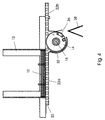
- the housing 30 moves back, i. H. a linear movement of the first follows and the second section 22a, 22b of the roller group 22 and the axis 16 in the through the direction indicated by the arrow C, which corresponds to the direction of the arrow B (FIG. 2) is opposite.
- the inside edge of the signature 32 is removed from the Gripper 36 released.
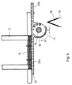
- the direction of rotation of the Reverse drum 14. This will open the signature 32 down on the saddle chain 38 pulled and released as shown in FIG. 6.
- a feed pin (not shown) on the saddle transport chain 38 pushes the signature 32 forward to the next one Feeding station where another signature is fed onto the saddle transport chain 38 can be.
- the singling drum 14 rotates further in the direction of arrow D and that Housing 30 moves linearly back over the bottom of signature stack 10 until it is in position to receive the next signature spine as in Fig. 7 shown. At this point the linear and rotary movements of the Drum 14 and the housing 30 begins to turn again in the opposite direction Arrow B to move. Since the position of the housing 30 with that given in Fig. 2 Position coincides, the singling drum 14 begins at the same time in the Move in the direction of arrow A to separate the next signature from stack 10.
- the feed device is relative to the Transport device 18, 38 arranged horizontally, but this can also be vertical be arranged as shown in Fig. 8.
- Signatures 42 are perpendicular to their folded ends.
- a singling drum 14 rotates in the direction of arrow D through one through the drum 14 extending axis 16. As described in connection with FIGS. 2 to 7, is by a combined linear movement B and rotary movement A of the drum 14 the first signature 42 is separated from the stack 10.
- the device can comprise a device which holds the stack on its supports the open end and the open surface of the separating drum 14 facing Stack 10 closes. As shown in Figs. 2-7, this device is together with the Axis 16 and thus also linearly movable with the singling drum 14.
- guide plates which are preferably equipped with elements are to the friction between the signature and the guide plate or one
- it is preferred a variety of rollers, d. H. to use a roller group the rollers being preferred are arranged parallel to the singling drum 14 and linear with it move.
- the rollers of the roller group can be driven in such a way that whose surfaces do not rub over the signatures.
- the rollers can also rotate freely by friction when moved over the bottom of the stack.
- the signature 42 has reached a position above the saddle 38, it is removed from the Drum 14 released, and the spread open signature falls on the saddle chain 38.
- the feeder 20 includes a bottomless one Signature holder 12 with a stack of signatures 10 and one arranged therein rotatable singling drum 14 with a extending through it Axis 16.
- the feed device 20 is arranged along a pocket conveyor 44, which has a plurality of pockets 48, in each of which one of the signatures of the Signature stack 10 is supplied.
- the signature 42 must have its folded edge first be moved down into the pocket 48. This is achieved by the timing the gripper attached to the singling drum 14 is regulated so that the Grippers or suction cups 34 and 36 cooperate in such a way that the signature then is released when their folded edge is in a leading, downward direction facing position.
- the signature 42 could also be used in the manner shown in FIGS. 2-7 folded edge to be fed into a pocket when the signatures in the Holders 12 are arranged such that the singling drum 14 is not the folded one Edge, but grabs the open edge of the signature.
- the signature 42 thus becomes one Position above the pocket moves, as already in connection with Fig. 2-7 described, but with the folded edge facing downwards.
- the feed device according to the present invention can also be used in conjunction with a Transport device used in the form of a conveyor belt, such as shown schematically in Fig. 10.
- the feed device 20 comprises one bottomless signature or sheet holder 12 with a stack of Signatures 10 and a rotatable singling drum 14 with one through them extending axis 16.
- the feed device 20 is along an as Conveyor belt designed conveyor 46 which is attached to the belt Has feed pins 50.
- To deliver the signature or sheet 42 precisely To ensure location 52 on the tape, the signatures 42 are individually separated from the stack 10 as described above with reference to Figures 2-7.
- the band conveyor However, 46 is located close to the end position of the drum 14, so that the Signature 42 can be stored on the tape in a suitable manner.
Landscapes
- Engineering & Computer Science (AREA)
- Mechanical Engineering (AREA)
- Sheets, Magazines, And Separation Thereof (AREA)
- Collation Of Sheets And Webs (AREA)
- Feeding Of Articles By Means Other Than Belts Or Rollers (AREA)
Abstract
Description
- Fig. 1
- eine schematische Seitenansicht einer ersten Ausführungsform der Zuführvorrichtung;
- Fig. 2
- eine schematische Seitenansicht der Zuführvorrichtung der Fig. 1 in einer ersten Position relativ zu einer Transporteinrichtung;
- Fig. 3
- eine schematische Seitenansicht der Zuführvorrichtung der Fig. 1 in einer zweiten Position relativ zur Transporteinrichtung;
- Fig. 4
- eine schematische Seitenansicht der Zuführvorrichtung der Fig. 1 in einer dritten Position relativ zur Transporteinrichtung;
- Fig. 5
- eine schematische Seitenansicht der Zuführvorrichtung der Fig. 1 in einer vierten Position relativ zur Transporteinrichtung;
- Fig. 6
- eine schematische Seitenansicht der Zuführvorrichtung der Fig. 1 in einer fünften Position relativ zur Transporteinrichtung;
- Fig. 7
- eine schematische Seitenansicht der Zuführvorrichtung der Fig. 1 in einer sechsten Position relativ zur Transporteinrichtung;
- Fig. 8
- eine schematische Seitenansicht einer alternativen Ausführungsform der Erfindung, bei der sich die Zuführvorrichtung senkrecht bewegt;
- Fig. 9
- eine perspektivische schematische Seitenansicht einer Zuführvorrichtung zum Zuführen der Produkte in einen Taschenförderer; und
- Fig. 10
- eine perspektivische schematische Seitenansicht einer Zuführvorrichtung zum Zuführen flacher Produkte auf ein Förderband.
- 10
- Signaturstapel
- 12
- Signaturhalter
- 14
- Vereinzelungstrommel
- 16
- Achse der Trommel 14
- 18
- Transporteinrichtung / Sattelförderer
- 20
- Zuführvorrichtung
- 22
- Walzengruppe
- 22a
- erster Abschnitt der Walzengruppe 22
- 22b
- zweiter Abschnitt der Walzengruppe 22
- 24
- einzelne Walze
- 26
- Hebelarm
- 28
- Antriebseinheit
- 30
- Gehäuse
- 32
- Signatur (Fig. 3)
- 34
- erster Greifer
- 36
- zweiter Greifer / Saugnapf
- 38
- Sattel-Transportkette
- 40
- Führungsplatte
- 42
- Signatur (Fig. 8)
- 44
- Taschenförderer
- 46
- Förderband/Band-Förderer
- 48
- Taschen
- 50
- Zuführstift
- 52
- Aufnahmestelle
- A, B, C, D
- Richtungspfeil
Claims (17)
- Vorrichtung zum Zuführen eines einzelnen flachen Produktes (32, 42), insbesondere eines Bogens oder einer Signatur, von einem Stapel (10) flacher Produkte zu einer Transporteinrichtung (38, 44, 46), mit einer Trommel (14) zum Ergreifen eines der flachen Produkte (32, 42) des Stapels (10),
dadurch gekennzeichnet,
daß die Trommel (14) um eine sich durch diese hindurch erstreckende Achse (16) drehbar ist, und daß ein Mechanismus vorgesehen ist, um die Trommel (14) entlang eines vorbestimmten Pfades zu bewegen, während sich diese dreht. - Vorrichtung nach Anspruch 1,
dadurch gekennzeichnet,
daß ferner ein Halter (12)vorgesehen ist, der den Stapel flacher Produkte (10) hält und eine Öffnung zum Abnehmen eines flachen Produktes (32) vom Stapel (10) aufweist, und daß Elemente (24) vorgesehen sind, die während der Bewegung der Trommel (14) den Stapel (10) in der Öffnung stützen. - Vorrichtung nach Anspruch 2,
dadurch gekennzeichnet,
daß die bewegbaren Elemente (24) zum Stützen des Stapels (10) eine Gruppe von Walzen (22) ist, die parallel zur Trommel (14) angeordnet und zusammen mit dieser bewegbar ist. - Vorrichtung nach Anspruch 3,
dadurch gekennzeichnet,
daß die Walzen (24) der Walzengruppe (22) durch eigene Antriebe angetrieben werden. - Vorrichtung nach Anspruch 3,
dadurch gekennzeichnet,
daß die Walzen (24) der Walzengruppe (22) aufgrund von Reibung frei rotieren. - Vorrichtung nach einem der Ansprüche 3 bis 5,
dadurch gekennzeichnet,
daß die Walzengruppe (22) einen ersten Abschnitt (22a) und einen zweiten Abschnitt (22b) aufweist, und daß der erste Abschnitt (22a) durch die Trommel (14) vom zweiten Abschnitt getrennt ist. - Vorrichtung nach einem der Ansprüche 1 bis 6,
dadurch gekennzeichnet,
daß eine Einrichtung zum Drehen der Trommel (14) vorgesehen ist, und daß die Einrichtung zum Bewegen der Trommel (14) mit der Einrichtung zum Drehen der Trommel (14) gekoppelt ist. - Vorrichtung nach Anspruch 7,
dadurch gekennzeichnet,
daß die Einrichtung zum Bewegen der Trommel (14) einen Zahnstangenmechanismus umfaßt. - Vorrichtung nach Anspruch 7,
dadurch gekennzeichnet,
daß die Einrichtung zum Bewegen der Trommel (14) einen Riemenscheibenmechanismus umfaßt. - Vorrichtung nach einem der Ansprüch 1-6,
dadurch gekennzeichnet,
daß eine Einrichtung zum Drehen der Trommel (14) vorgesehen ist, und daß die Einrichtung zum Bewegen der Trommel (14) und die Einrichtung zum Drehen der Trommel (14) unabhängig voneinander angetrieben werden. - Vorrichtung nach Anspruch 10
dadurch gekennzeichnet,
daß der Antrieb durch einen Servomotor erfolgt. - Vorrichtung nach Anspruch 10
dadurch gekennzeichnet,
daß der Antrieb durch einen Zahnstangenmechanismus erfolgt. - Anlage zum Zusammentragen flacher Produkte, die eine Produkttransporteinrichtung (18, 44, 46) aufweist,
gekennzeichnet durch eine Vielzahl von Zuführvorrichtungen (14, 22, 30) nach einem der Ansprüche 1-12, die entlang der Transporteinrichtung (18, 44, 46) zum Zuführen eines einzelnen flachen Produktes (32, 42) angeordnet sind. - Verfahren zum Zuführen flacher Produkte, insbesondere von Bogen oder Signaturen, von einem Stapel flacher Produkte zu einer Transporteinrichtung, wobei das Verfahren das die folgenden Schritte umfaßt:Drehen einer Vereinzelungstrommel in eine erste Richtung um eine sich durch die Trommel hindurch erstreckende Achse, wobei die Trommel an einer zugänglichen Seite des Stapels angeordnet ist und während des Drehens eines der flachen Produkte des Stapels ergreift;Trennen eines der flachen Produkte vom Stapel und Wickeln des flachen Produktes um die Trommel, während die Trommel gleichzeitig entlang eines vorbestimmten Pfades von einer Startposition zu einer Endposition bewegt wird.
- Verfahren nach Anspruch 14,
gekennzeichnet durch folgende weitere Schritte:Stoppen der Bewegung und der Umdrehung der Trommel an der Endposition;Zuführen des flachen Produktes zu einer Transporteinrichtung, während die Trommel zur Startposition linear bewegt und gleichzeitig in eine der ersten Drehrichtung entgegengesetzten Richtung gedreht wird. - Verfahren nach Anspruch 14 oder 15,
dadurch gekennzeichnet,
daß das Verhältnis zwischen der Bewegungsgeschwindigkeit der Trommel und der Drehgeschwindigkeit der Trommel konstant ist. - Verfahren nach Anspruch 14 oder 15,
dadurch gekennzeichnet,
daß das Verhältnis zwischen der Bewegungsgeschwindigkeit der Trommel und der Drehgeschwindigkeit der Trommel variabel ist, während diese sich bewegt und dreht.
Applications Claiming Priority (2)
| Application Number | Priority Date | Filing Date | Title |
|---|---|---|---|
| GB9818113 | 1998-08-19 | ||
| GB9818113A GB2340825A (en) | 1998-08-19 | 1998-08-19 | Signature feed |
Publications (2)
| Publication Number | Publication Date |
|---|---|
| EP0980839A2 true EP0980839A2 (de) | 2000-02-23 |
| EP0980839A3 EP0980839A3 (de) | 2000-10-18 |
Family
ID=10837539
Family Applications (1)
| Application Number | Title | Priority Date | Filing Date |
|---|---|---|---|
| EP99114294A Withdrawn EP0980839A3 (de) | 1998-08-19 | 1999-07-29 | Zuführvorrichtung |
Country Status (2)
| Country | Link |
|---|---|
| EP (1) | EP0980839A3 (de) |
| GB (1) | GB2340825A (de) |
Cited By (3)
| Publication number | Priority date | Publication date | Assignee | Title |
|---|---|---|---|---|
| JP2002046195A (ja) * | 2000-06-30 | 2002-02-12 | Focke & Co Gmbh & Co | 包装機におけるブランク取り扱い装置 |
| EP1520817A1 (de) * | 2003-10-02 | 2005-04-06 | Müller Martini Holding AG | Verfahren und Einrichtung zur Herstellung gebundener Bücher, Zeitschriften oder Broschüren |
| CN104370128A (zh) * | 2014-11-12 | 2015-02-25 | 苏州三屹晨光工业设备有限公司 | 电池初次顶侧密封机的软铝投入机构 |
Family Cites Families (7)
| Publication number | Priority date | Publication date | Assignee | Title |
|---|---|---|---|---|
| DE278131C (de) * | ||||
| US1520022A (en) * | 1922-10-09 | 1924-12-23 | Sigwald C Grunlee | Machine for separating and gathering sheets of paper |
| GB897056A (en) * | 1958-08-15 | 1962-05-23 | Rose Brothers Ltd | Improvements in sheet-feeding apparatus |
| DE1246529B (de) * | 1962-04-09 | 1967-08-03 | Windmoeller & Hoelscher | Kunststoff-Ventilsack, der aus einem an den Enden durch Verschweissen der Kanten verschlossenen Seitenfaltenschlauchabschnitt besteht |
| DE1278397B (de) * | 1962-07-16 | 1968-09-26 | Leipziger Buchbindereimaschine | Vorrichtung zum Auflegen gefalzter Bogen auf einen dachfoermigen Sattel einer Heftmaschine |
| DE3808651C2 (de) * | 1988-03-15 | 1997-12-04 | Hoerauf Michael Maschf | Vorrichtung zum Ergreifen und Vereinzeln des unteren Zuschnittes eines Stapels von Zuschnitten aus kaschiertem Papier o. dgl., insbesondere für eine Buchdeckenmaschine |
| DE3823705A1 (de) * | 1988-07-13 | 1990-01-18 | Schmermund Maschf Alfred | Vorrichtung zum vereinzeln von zuschnitten aus einem stapel |
-
1998
- 1998-08-19 GB GB9818113A patent/GB2340825A/en not_active Withdrawn
-
1999
- 1999-07-29 EP EP99114294A patent/EP0980839A3/de not_active Withdrawn
Cited By (5)
| Publication number | Priority date | Publication date | Assignee | Title |
|---|---|---|---|---|
| JP2002046195A (ja) * | 2000-06-30 | 2002-02-12 | Focke & Co Gmbh & Co | 包装機におけるブランク取り扱い装置 |
| EP1167008A3 (de) * | 2000-06-30 | 2003-01-02 | Focke & Co. (GmbH & Co.) | Vorrichtung zum Zuführen von Packungszuschnitten |
| EP1520817A1 (de) * | 2003-10-02 | 2005-04-06 | Müller Martini Holding AG | Verfahren und Einrichtung zur Herstellung gebundener Bücher, Zeitschriften oder Broschüren |
| US7419153B2 (en) | 2003-10-02 | 2008-09-02 | Muller Martini Holding Ag | Method and apparatus for producing bound books, magazines or brochures |
| CN104370128A (zh) * | 2014-11-12 | 2015-02-25 | 苏州三屹晨光工业设备有限公司 | 电池初次顶侧密封机的软铝投入机构 |
Also Published As
| Publication number | Publication date |
|---|---|
| GB9818113D0 (en) | 1998-10-14 |
| GB2340825A (en) | 2000-03-01 |
| EP0980839A3 (de) | 2000-10-18 |
Similar Documents
| Publication | Publication Date | Title |
|---|---|---|
| DE102012003604B4 (de) | Vorrichtung zum Zuführen von Buchblocks in den Einfuhrkanal einer Weiterverarbeitungseinrichtung | |
| EP0346578B1 (de) | Einrichtung zum Sammeln, Zusammentragen und Einstecken von Druckereiprodukten | |
| CH667621A5 (de) | Sammelhefter. | |
| DE60105455T2 (de) | Wendevorrichtung für graphische Information darstellende Produkte in einer Förderstecke und/oder einer Verpackungsmaschine | |
| DE3145491C2 (de) | ||
| DE69029000T2 (de) | Vorrichtung und Verfahren zum Zusammenstellen von blattförmigem Material | |
| DE3620945A1 (de) | Verfahren und vorrichtung zum sammeln von gefalzten druckbogen | |
| EP0908408B1 (de) | Vorrichtung und Verfahren für das kombinierte Zusammentragen und Binden von bogenförmigen Produkten | |
| DE2634982B2 (de) | Vorrichtung zur Bildung eines Stapels aus kreuzweise übereinander abgelegten Teilstapeln | |
| EP4371173A2 (de) | Zellstapelanlage und zellstapelvorrichtung für segmente von energiezellen und teilvorrichtung/teilverfahren einer oder in einer zellstapelanlage | |
| CH625481A5 (de) | ||
| EP1351873B1 (de) | Vorrichtung zum verarbeiten von druckereiprodukten | |
| DE2312512A1 (de) | Vorrichtung zum einsetzen eines bindeelements in die randperforation von loseblaettern | |
| DE69712573T2 (de) | Vorrichtung zum Drehen von Verlagsprodukten auf einer Verpackungsstrasse | |
| DE3330681C2 (de) | ||
| EP0754642A2 (de) | Vorrichtung zur Auslage bogenförmiger Produkte | |
| EP0514783B1 (de) | Vorrichtung zum Fördern von Papierbogenstapeln | |
| EP0681979B1 (de) | Einrichtung zum Verarbeiten von Druckereiprodukten | |
| DE68905961T2 (de) | Verfahren und vorrichtung zum zufuehren von signaturen zu einer heftmaschine. | |
| DE19821022B4 (de) | Vorrichtung zum Abbremsen von Bogenmaterial unter Beibehaltung der Ausrichtung der Bogen | |
| DE69811989T2 (de) | Verfahren und Vorrichtung zur Orientierung von Bögen oder Gruppen von Bögen, insbesondere Banknoten | |
| EP0286868B1 (de) | Vorrichtung zum Vereinigen von zwei Teilstapeln von Buchseiten | |
| EP0806391A1 (de) | Vorrichtung zum Zubringen von Druckereierzeugnissen zu einer Weiterverarbeitungsstelle | |
| EP1657199B1 (de) | Vorrichtung zum Bearbeiten von flachen Produkten, insbesondere Druckprodukten | |
| EP0657375B1 (de) | Einrichtung zur Beschickung einer Druckbogen verarbeitenden Maschine |
Legal Events
| Date | Code | Title | Description |
|---|---|---|---|
| PUAI | Public reference made under article 153(3) epc to a published international application that has entered the european phase |
Free format text: ORIGINAL CODE: 0009012 |
|
| AK | Designated contracting states |
Kind code of ref document: A2 Designated state(s): AT BE CH CY DE DK ES FI FR GB GR IE IT LI LU MC NL PT SE |
|
| AX | Request for extension of the european patent |
Free format text: AL;LT;LV;MK;RO;SI |
|
| PUAL | Search report despatched |
Free format text: ORIGINAL CODE: 0009013 |
|
| AK | Designated contracting states |
Kind code of ref document: A3 Designated state(s): AT BE CH CY DE DK ES FI FR GB GR IE IT LI LU MC NL PT SE |
|
| AX | Request for extension of the european patent |
Free format text: AL;LT;LV;MK;RO;SI |
|
| RIC1 | Information provided on ipc code assigned before grant |
Free format text: 7B 65H 3/10 A, 7B 65H 3/06 B, 7B 65H 3/08 B, 7B 65H 5/10 B, 7B 65H 5/12 B, 7B 65H 5/30 B |
|
| AKX | Designation fees paid | ||
| STAA | Information on the status of an ep patent application or granted ep patent |
Free format text: STATUS: THE APPLICATION IS DEEMED TO BE WITHDRAWN |
|
| 18D | Application deemed to be withdrawn |
Effective date: 20010419 |
|
| REG | Reference to a national code |
Ref country code: DE Ref legal event code: 8566 |